
Scope and sources
This is a task-focused engineering guide, not a page-by-page translation of the complete PDF. Source examples are not ArmSoM measurements. Check voltages, pins, SDK/BSP and kernel against the actual board revision.
Rockchip: RK3576_Hardware_Design_Guide_V1.1_20240528_CN.pdf · V1.1 · §2.1, §2–3
Establish a minimum system
Section 2.1 of the RK3576 Hardware Design Guide V1.1 covers clocks, reset, boot, JTAG, UART and memory. Start with a configuration that boots repeatedly, provides a serial log and permits recovery. Add cameras, displays and high-speed peripherals one at a time so that failures can be associated with a specific change.
DDR, clocks and regulators are part of a custom SoC board’s minimum system. With CM5, begin with the module interface and carrier documentation instead: internal chip rails are not module supply inputs. Sige5 can establish an application baseline, but does not validate the electrical design of another board.
Five checks before accepting first boot
| Area | Before power | Evidence to retain |
|---|---|---|
| Power | BOM, voltage, polarity, shorts and current limit | Input current, rails and startup transients |
| Clock | Crystal, load network and routing | Frequency and waveform measured with a suitable probing method |
| Reset | Supply domain, pulls and reset sources | Timing of rail stabilization and reset release |
| Boot | Media, configuration resistors, Loader and board revision | Complete boot log through the kernel |
| Debug | UART, recovery path and test points | Repeatable cold boots, resets and recovery |
Section 2.1.1 describes a main-clock circuit using an external 24MHz crystal. It does not instruct CM5 carrier designers to duplicate that circuit. Reset and UART voltage levels must also match the actual signal domains.
Narrow down startup failures
For a silent serial port, check adapter voltage, ground, TX/RX, baud rate, power and reset before replacing the image. If Loader runs but the kernel does not, check DDR initialization, storage, image and device-tree compatibility. Once Linux boots, investigate peripheral power, pin multiplexing, clocks and drivers separately.
Change one variable at a time. Record schematic and module revisions, the image checksum and logs. A successful boot is followed by repeated cold starts, power-loss recovery and load testing; one boot is not a production acceptance test.
Apply the method with ArmSoM
Establish a software baseline on the CM5 companion IO board before moving to a custom carrier. On Sige5, record peripheral models, cables and power conditions. This workflow is an engineering checklist, not a universal voltage table or a substitute for a board-specific review.
Source illustration
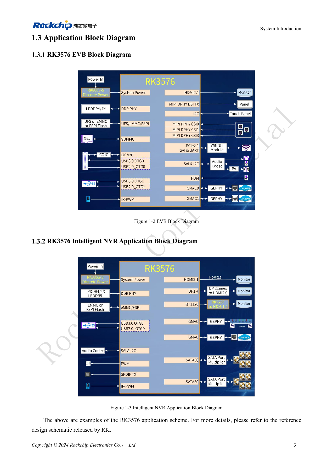
Original from the English document, shared by EN/RU/DE. Reference design, not an ArmSoM board schematic.
RK3576_Hardware_Design_Guide_V1.1_20240528_EN.pdf · PDF p. 22.
Products and development resources
- CM5 — Product page · Documentation
- Sige5 — Product page · Documentation
Continue this series
- ArmSoM CM5 carrier-board checklist: power, boot and interface planning
- RK3576 high-speed interfaces: review schematics and PCB together
- RK3588S hardware design: from a reference circuit to a CM7s carrier
- RK3588 edge-AI hardware: plan power, cooling and expansion together
- RK3588 high-speed PCB review: stackup, impedance and routing
- RK3506 industrial HMI hardware: choosing a CM1 or Forge1 development path
- RK3308 hardware variants: compatibility checks for P2 Pro audio projects
- RK3588S versus RK3588S2: what to check before a hardware revision
- Rockchip prototype to production: process requirements and test records
RK3576 minimum system: from schematic review to repeatable first boot
A minimum system must cold-boot repeatedly, provide complete logs and permit recovery. Establish power, clocks, reset, DDR, boot storage and debug access before adding displays, cameras and high-speed peripherals. The following extends the existing bring-up workflow with specific design-guide constraints.
Based on the Chinese and English RK3576 Hardware Design Guide V1.1 (2024-05-28), for SoC-board design. CM5 carriers must follow the module interface; Sige5 can establish a software/peripheral baseline. This guide does not prescribe one SDK/BSP or kernel for every product; verify each board. Values are source references, not ArmSoM measurements.
RK3576_Hardware_Design_Guide_V1.1_20240528_EN.pdf · §2.1–2.2
Separate SoC boards from module carriers
A custom RK3576 board requires internal rail, DDR and PMIC design. A CM5 carrier follows the module input supply, connectors and signal definitions; never apply an internal SoC rail voltage to an assumed module pin. Sige5 provides a software/peripheral baseline, not electrical validation of another PCB.
Locate the failing boot stage
With no UART output, check ground, voltage, TX/RX, the default 1500000bps setting, 24MHz and RESET_L. If Loader reports DDR initialization failure, check the memory part, layout template and DDR firmware. After the kernel starts, investigate device tree, supplies, clocks and pin multiplexing. Change one variable at a time and retain failed logs.
Make validation reproducible
Record PCB/BOM revisions, image checksum, Loader/DDR firmware, SDK/BSP, kernel, input supply and peripherals. Save supply/reset waveforms using consistent reference points; exercise cold boot, software restart, interrupted power and recovery download. These tests have not been performed here on ArmSoM hardware, and no universal repetition count is prescribed.
Design parameters and review table
| Item | Value or net | Review note |
|---|---|---|
| Main clock | 24MHz | Check crystal and load; reference capacitors are not universal |
| Reset release | ≥1ms | After the last rail settles; distinct from pulse width |
| Recovery access | USB2_OTG0_DP/DM + VBUSDET | Reserve even for a host-only product |
| DDR address/data | DQ/CA | No arbitrary swapping; follow template and memory definition |
Reference circuits and figures
The reference pages below contain the relevant circuit or timing figures; click for full resolution. Designators and component values belong to the reference design, not an ArmSoM product schematic.
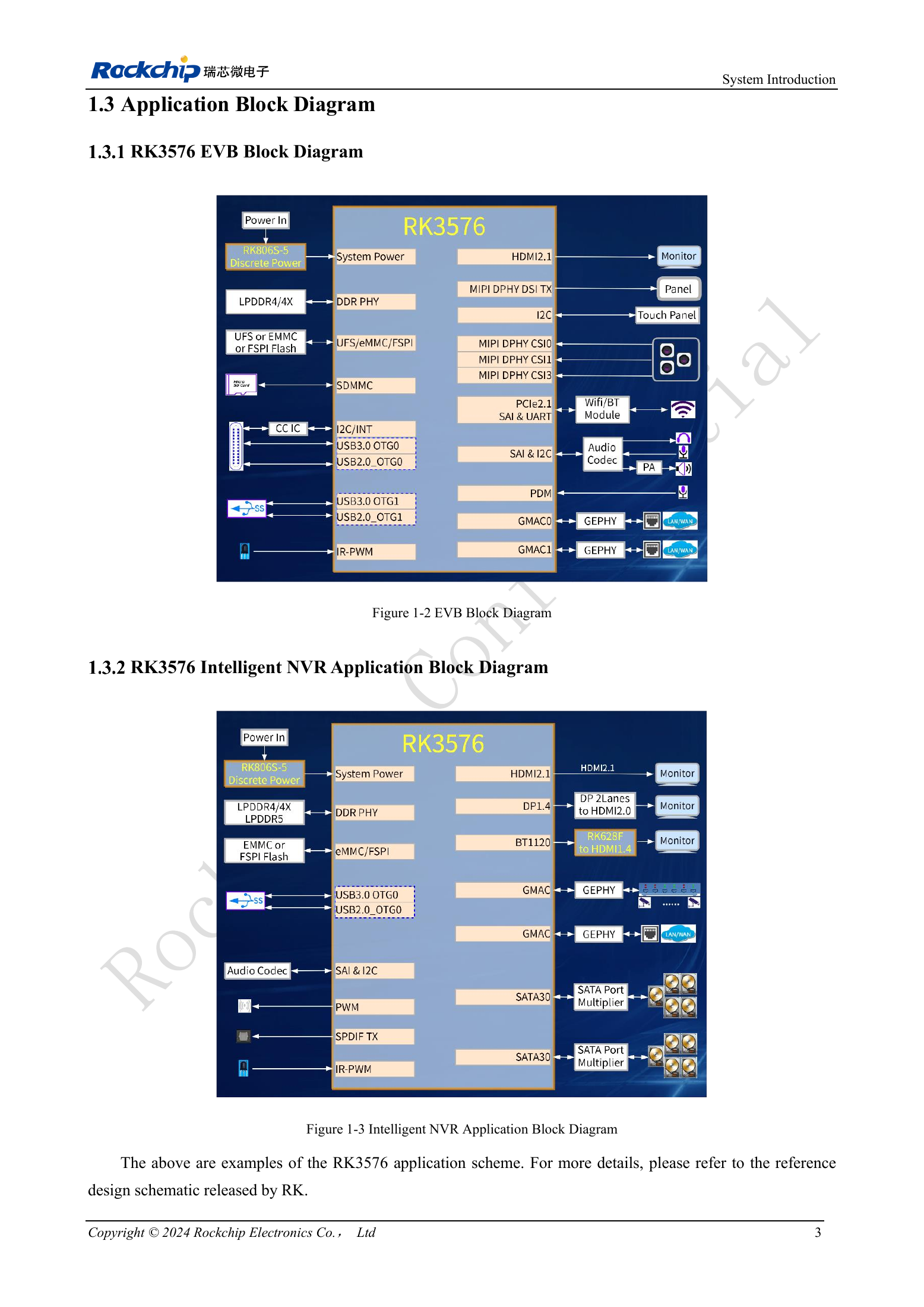
English original · PDF 22 · 1-2 / 1-3
ArmSoM products and development path
CM5 brings integrated computing to a custom carrier; Sige5 supports initial Linux and peripheral evaluation. SoC interface capability does not mean both products expose it. Check connectors, board revision and system image before purchasing or layout.
Series reading order
- RK3576 hardware design series: from minimum system to DDR and USB
- RK3576 clock design: 24MHz crystal, 32kHz standby and peripheral clocks
- RK3576 reset design: NPOR, RK806S-5, watchdog and thermal shutdown
- RK3576 boot and debug design: straps, Maskrom, UART and JTAG
- RK3576 rails and decoupling: CPU, GPU, NPU and LOGIC supply planning
- RK3576 and RK806S-5: PMIC selection, control pins and feedback
- RK3576 power sequencing and standby: reset, retained rails and wake paths
- RK3576 DDR circuits and power: LPDDR4, LPDDR4X and LPDDR5
- RK3576 DDR PCB routing: impedance, length, return paths and PDN
- RK3576 USB and Type-C hardware supplement: multiplexing, recovery and protection