
Scope and sources
This is a task-focused engineering guide, not a page-by-page translation of the complete PDF. Source examples are not ArmSoM measurements. Check voltages, pins, SDK/BSP and kernel against the actual board revision.
Rockchip: RK3576_Production_Process_Requirements_V10_20240522_CN.pdf · V1.0 · §1–3
Separate chip reflow from module assembly
A chip reflow profile applies to its package context, not automatically to reflowing a complete CM5, CM7s or AIM7 module. Connectors, thermal materials and enclosures have their own assembly requirements. Modules reduce the scope of SoC assembly work, but carrier and product quality still need independent control.
What the source specifies
Section 1.3 provides references for process engineers to validate against the board, paste and equipment, not an unmeasured production recipe.
| Item | Source reference |
|---|---|
| Paste | SAC305; flux fraction 10%–11.5% |
| Rising slope | 1–2℃/s |
| Soak at 150–180℃ | 60–90s |
| Above 220℃ | 60–80s |
| Peak | 245±5℃; 15–30s |
| Falling slope | Recommended ≤2℃/s |
Section 3.2.2 gives rounded square apertures with r=0.05mm, side 0.30–0.32mm and stencil thickness 0.1mm. These belong to the RK3576 context, not every package.
Storage wording needs clarification
Section 2.2 states MSL 3, ≤30℃/60%RH and recommended use within 168 hours after opening, but also mentions a six-hour pre-reflow dwell. The MSL 1 table row says “≤300℃/85%RH”. These are source statements with unresolved conditions or values. Do not use 300℃ as storage advice or silently discard six hours. Obtain supplier clarification and follow the lot label and applicable process specification.
Documents for the factory
- Versioned schematic, BOM, PCB, assembly and test files.
- Complete module and peripheral part numbers, revisions and substitution rules.
- Confirmed process parameters, measured profiles and exception handling.
- Image checksum, programming procedure, serial-number assignment and results reporting.
Separate supply checks, boot, interface function and sustained-load tests. Use pilot-build results to establish release criteria; a desktop demonstration is not factory acceptance. Retain review and retest records after process or component changes.
Source illustration
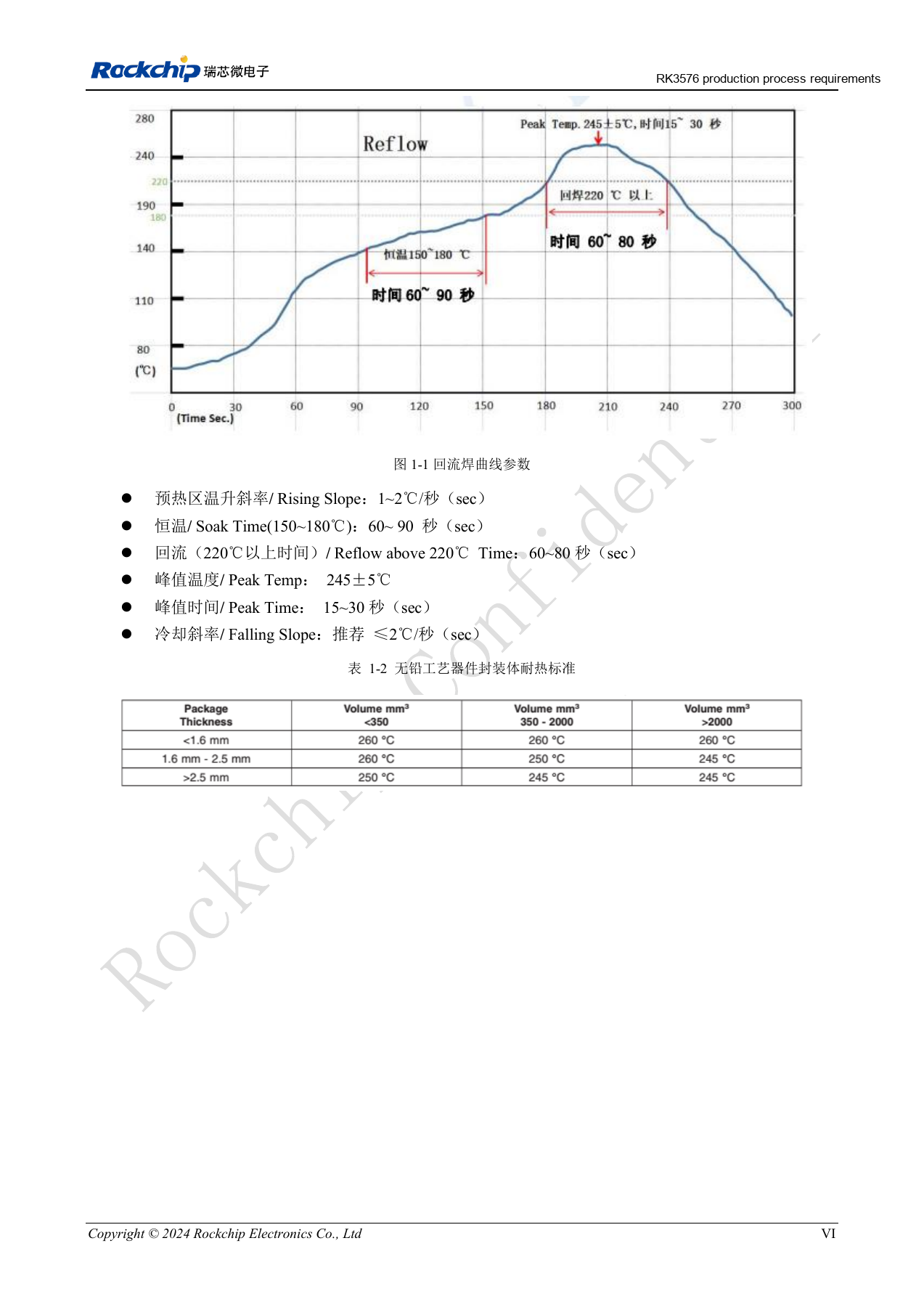
Chinese original; no matching English figure was found in the supplied materials. Reference design, not an ArmSoM board schematic.
RK3576_Production_Process_Requirements_V10_20240522_CN.pdf · PDF p. 7.
Add the RK3588 process reference without merging platforms
This supplement uses the technical body of the eight-page RK3588 Production Process Requirements V1.0_20230215.pdf. It extends the RK3576 guide while keeping each platform’s values separate. These are process-review references, not automatic permission to reflow complete ArmSoM modules or a universal assembly recipe.
| Parameter | Existing RK3576 reference | Added RK3588 reference |
|---|---|---|
| Paste alloy / flux fraction | SAC305; 10%–11.5% | SAC305; 10%–11.5% |
| Rising slope | 1–2℃/s | 1–2℃/s |
| Soak at 150–180℃ | 60–90s | 60–120s |
| Above 220℃ | 60–80s | 60–90s |
| Peak | 245±5℃; 15–30s | 245±5℃; 15–30s |
| Falling slope | Recommended ≤2℃/s | Recommended ≤2℃/s |
| Stencil thickness | 0.1mm | 0.1–0.12mm |
Soak, time above liquidus and stencil thickness differ. Selecting the widest intervals would create a rule that neither source gives for every Rockchip device.
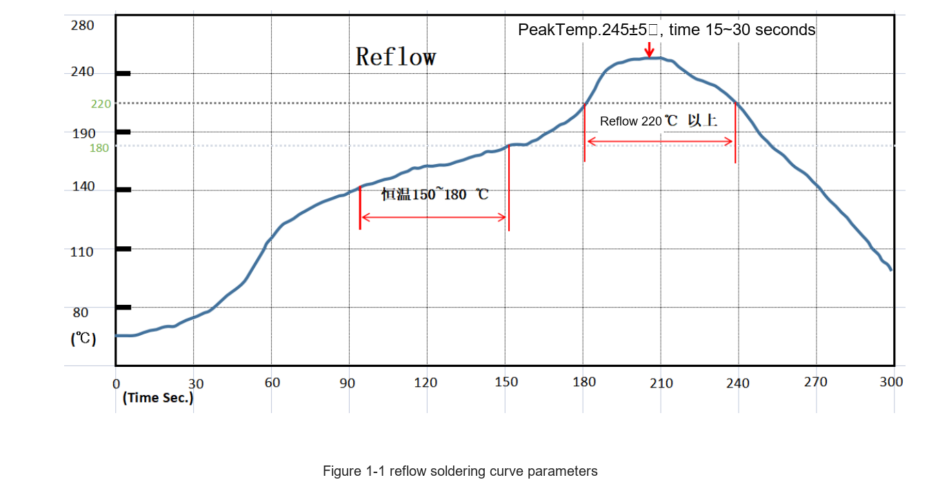
RK3588 vendor reflow-profile illustration — Original Chinese figure; no corresponding English figure was found in this batch. RK3588 Production Process Requirements V1.0_20230215.pdf, PDF p. 6.
Validate the profile on the actual assembly
The RK3588 source also gives paste refrigeration at 2–10℃ and warming for 3–4h. Execution must meet the paste lot specification and approved process. Record oven settings, conveyor speed, board thermocouple locations and measured profile. Oven setpoints are not solder-joint temperatures.
Package, copper weight, board thickness, density and thermal mass change heating. Pilot builds should evaluate defects and consistency, retaining rework, repeated-reflow and lot records. A reference-board profile does not remove validation of a different PCB.
Retain the stencil wording ambiguity
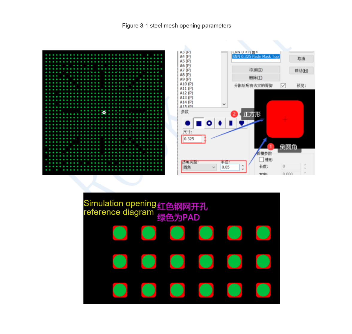
RK3588 original stencil-aperture illustration — Original Chinese figure; no corresponding English figure was found in this batch. RK3588 Production Process Requirements V1.0_20230215.pdf, PDF p. 8.
Page 8 describes a square aperture with rounded corners r=0.05mm, then calls the size a “diameter=0.325~0.35mm”, with 0.1–0.12mm stencil thickness. Square versus diameter is ambiguous. This guide does not silently turn it into a side length. Confirm production data with the supplier and stencil manufacturer against the formal package/process specification.
Moisture handling and baking are conditional
Page 7 lists MSL 3, ≤30℃/60%RH and 168h after opening, while also mentioning 6h before reflow. The MSL 1 table prints ≤300℃/85%RH. Do not use 300℃ as storage advice; the relationship between 168h and 6h also needs clarification.
The same page gives 125±5℃ for 8–12h after moisture exposure and dry storage below <20%RH. These describe the bare-chip source context. They must not be applied directly to modules containing plastic connectors, batteries, adhesives or other parts. Follow the package label, lot moisture state and approved process, retaining opening, exposure and bake records.
Modules still need production traceability
AIM7 or LM7 changes the scope of custom-board assembly but does not remove connector, soldering, carrier and system requirements. Link each serial number to hardware/BOM, firmware checksum, programming result, supply, DDR/storage, network/display and thermal tests. Failures should be traceable to a lot and reproducibly retestable.
The RK3588 addition remains separate from the earlier RK3576 values and unresolved wording. No production-line trial was performed for this update.
Products and development resources
- CM5 — Product page · Documentation
- CM7s — Product page · Documentation
- AIM7 — Product page · Documentation
- LM7 — Product · Documentation
- Sige7 — Product · Documentation
Continue this series
- RK3576 hardware bring-up: minimum system and first-power checks
- ArmSoM CM5 carrier-board checklist: power, boot and interface planning
- RK3576 high-speed interfaces: review schematics and PCB together
- RK3588S hardware design: from a reference circuit to a CM7s carrier
- RK3588 edge-AI hardware: plan power, cooling and expansion together
- RK3588 high-speed PCB review: stackup, impedance and routing
- RK3506 industrial HMI hardware: choosing a CM1 or Forge1 development path
- RK3308 hardware variants: compatibility checks for P2 Pro audio projects
- RK3588S versus RK3588S2: what to check before a hardware revision