
The reset net connects the SoC, PMIC, watchdog and temperature protection. Review direction, voltage domain, low-pulse duration and total net capacitance rather than merely adding a reset button.
Based on the Chinese and English RK3576 Hardware Design Guide V1.1 (2024-05-28), for SoC-board design. CM5 carriers must follow the module interface; Sige5 can establish a software/peripheral baseline. This guide does not prescribe one SDK/BSP or kernel for every product; verify each board. Values are source references, not ArmSoM measurements.
RK3576_Hardware_Design_Guide_V1.1_20240528_EN.pdf · §2.1.2; §2.2.3
NPOR timing
NPOR (Pin W28) is active low. The source specifies at least 100 cycles of 24MHz, while also stating “at least 4μs”. Since 100/24MHz≈4.167μs, retain the 100-cycle requirement; 4μs is approximate and an exact 4.000μs pulse does not provide 100 cycles. The ≥1ms interval from final rail stabilization to RESET_L release is a separate startup requirement.
RESETB changes its role
At initial power-up RK806S-5 holds RESETB low, then releases it after the rails and delay are valid; an external pull-up raises the net. Pulling RESETB low during operation or sleep restarts the PMIC and repeats sequencing. Pull RESET_L up to PMUIO0_VCC1V8. The reference uses 100nF on the reset net, but the PMIC requires total capacitance ≤0.3μF; do not accumulate capacitors on every branch.
Watchdog and thermal protection
TSADC1 has six channels. At a configured threshold it can signal CRU through internal TSADC_SHUT and drive TSADC_CTRL_M0 low. An external watchdog connected to that net must have an open-drain output to avoid contention. Observe reset, rail restart and UART logs together; check BSP thresholds, watchdog routing and recovery policy. No unverified universal temperature threshold is supplied.
Design parameters and review table
| Item | Value or net | Review note |
|---|---|---|
| External reset | NPOR / W28 | Active low; at least 100×24MHz periods |
| Pull-up rail | PMUIO0_VCC1V8 | Do not arbitrarily use 3.3V |
| Total net capacitance | ≤0.3μF | Include SoC, PMIC and external reset branches |
Reference circuits and figures
The reference pages below contain the relevant circuit or timing figures; click for full resolution. Designators and component values belong to the reference design, not an ArmSoM product schematic.
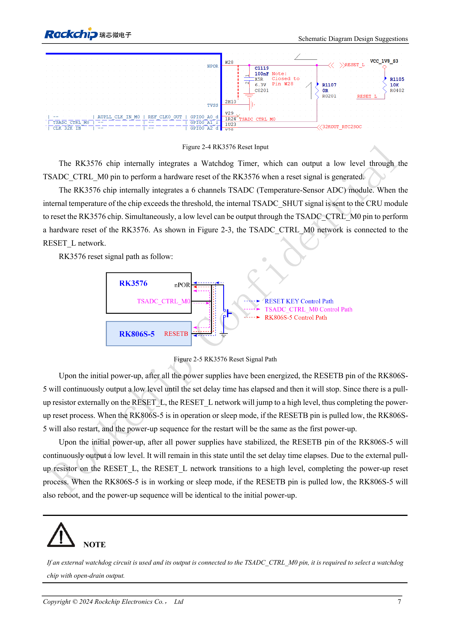
English original · PDF 26 · 2-4
ArmSoM products and development path
CM5 brings integrated computing to a custom carrier; Sige5 supports initial Linux and peripheral evaluation. SoC interface capability does not mean both products expose it. Check connectors, board revision and system image before purchasing or layout.
Series reading order
- RK3576 hardware design series: from minimum system to DDR and USB
- RK3576 minimum system: from schematic review to repeatable first boot
- RK3576 clock design: 24MHz crystal, 32kHz standby and peripheral clocks
- RK3576 boot and debug design: straps, Maskrom, UART and JTAG
- RK3576 rails and decoupling: CPU, GPU, NPU and LOGIC supply planning
- RK3576 and RK806S-5: PMIC selection, control pins and feedback
- RK3576 power sequencing and standby: reset, retained rails and wake paths
- RK3576 DDR circuits and power: LPDDR4, LPDDR4X and LPDDR5
- RK3576 DDR PCB routing: impedance, length, return paths and PDN
- RK3576 USB and Type-C hardware supplement: multiplexing, recovery and protection