
Review rail voltage, transient current, decoupling placement and standby state together. The following values come from the reference design or vendor examples; they are neither CM5 input specifications nor ArmSoM power measurements.
Based on the Chinese and English RK3576 Hardware Design Guide V1.1 (2024-05-28), for SoC-board design. CM5 carriers must follow the module interface; Sige5 can establish a software/peripheral baseline. This guide does not prescribe one SDK/BSP or kernel for every product; verify each board. Values are source references, not ArmSoM measurements.
RK3576_Hardware_Design_Guide_V1.1_20240528_EN.pdf · §2.2.1–2.2.4
Do not disable rails merely from the application name
NPU power is required at initial startup even without an AI workload; the guide permits conditional GPU shutdown. Boot media determine required IO rails: eMMC/FSPI0 use VCCIO0, SDMMC0/FSPI1_M0 use VCCIO1, FSPI1_M1 uses VCCIO3, and UFS also requires VCCIO7, oscillator and PHY supplies. PMUIO0/1 are mandatory. Other rails can be disabled only with complete sequencing, wake and peripheral requirements satisfied.
Capacitors must serve the load
Total big-core capacitance must exceed 130μF and little-core capacitance 88μF. GPU main decoupling exceeds 66μF, NPU 90μF and LOGIC total 88μF. Distinguish PMIC output capacitance from near-SoC decoupling; do not place the entire capacitance beside the regulator. Evaluate DC-bias derating, loops, transients and probing. LOGIC_MEM normally shares LOGIC; separate power also needs DVFS software review.
Do not sum module peaks into board power
Vendor table 2-19 records separate extreme module workloads at 25°C on a bare board without a heatsink after 15 minutes of stable operation. Its entries are not a simultaneous whole-board workload. Add measurements of the actual concurrent workload, distinguishing peak current, sustained current and input power.
Design parameters and review table
| Item | Value or net | Review note |
|---|---|---|
| Big CPU | BUCK1; >4A; >130μF | Default reference voltage 0.85V |
| Little CPU | BUCK3; >2A; >88μF | Total decoupling |
| Graphics | BUCK5; 3A; >66μF | Main decoupling near SoC |
| NPU | BUCK2; >4A; >90μF | Do not omit startup power when AI is unused |
| Logic | BUCK7; >2A; >88μF | Keep LOGIC_MEM sharing consistent |
Reference circuits and figures
The reference pages below contain the relevant circuit or timing figures; click for full resolution. Designators and component values belong to the reference design, not an ArmSoM product schematic.
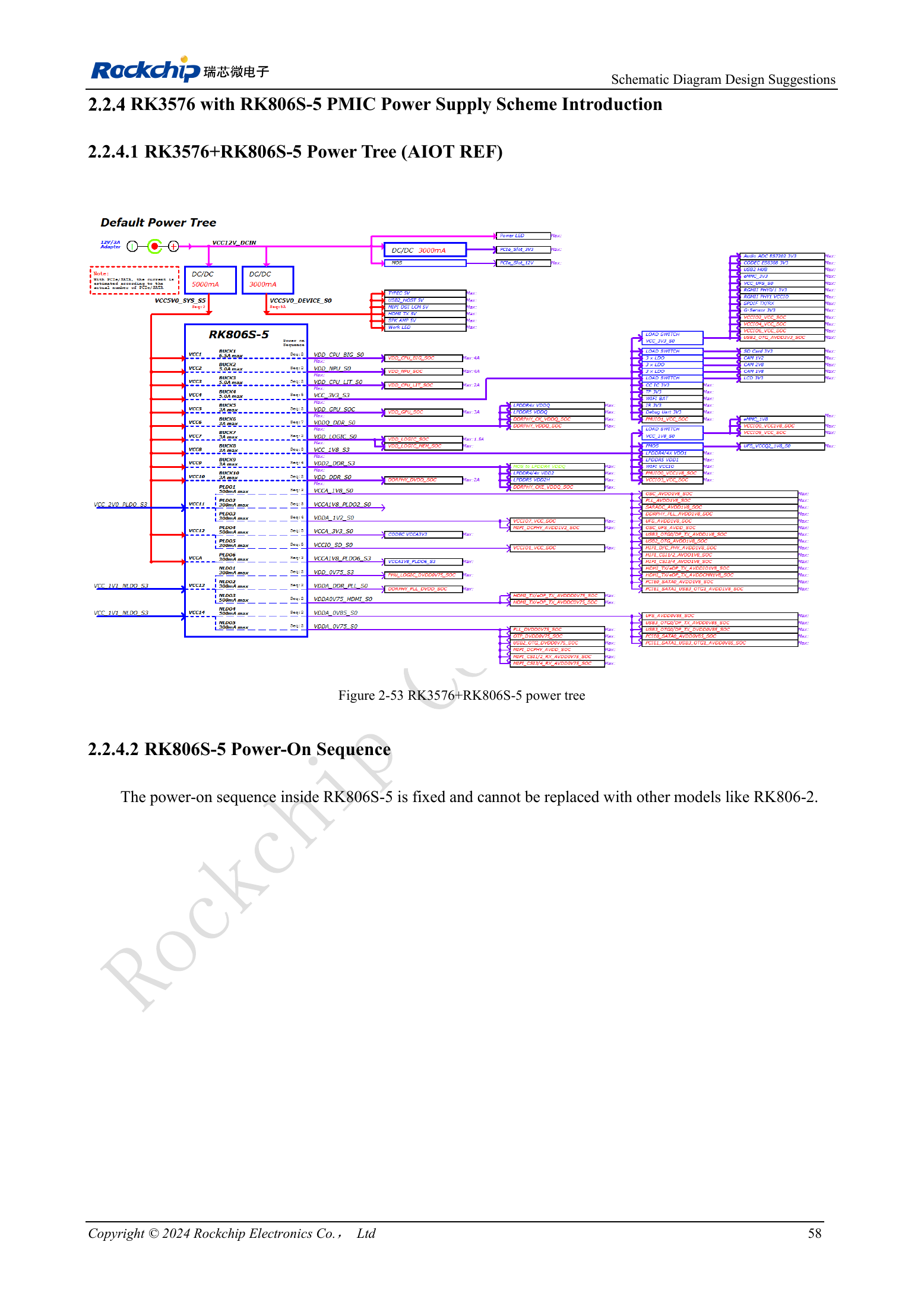
English original · PDF 77 · 2-53
ArmSoM products and development path
CM5 brings integrated computing to a custom carrier; Sige5 supports initial Linux and peripheral evaluation. SoC interface capability does not mean both products expose it. Check connectors, board revision and system image before purchasing or layout.
Series reading order
- RK3576 hardware design series: from minimum system to DDR and USB
- RK3576 minimum system: from schematic review to repeatable first boot
- RK3576 clock design: 24MHz crystal, 32kHz standby and peripheral clocks
- RK3576 reset design: NPOR, RK806S-5, watchdog and thermal shutdown
- RK3576 boot and debug design: straps, Maskrom, UART and JTAG
- RK3576 and RK806S-5: PMIC selection, control pins and feedback
- RK3576 power sequencing and standby: reset, retained rails and wake paths
- RK3576 DDR circuits and power: LPDDR4, LPDDR4X and LPDDR5
- RK3576 DDR PCB routing: impedance, length, return paths and PDN
- RK3576 USB and Type-C hardware supplement: multiplexing, recovery and protection