
Scope and sources
This is a task-focused engineering guide, not a page-by-page translation of the complete PDF. Source examples are not ArmSoM measurements. Check voltages, pins, SDK/BSP and kernel against the actual board revision.
Rockchip: RK3506 Hardware Design Guide_V1.0_20240904_CN.pdf · V1.0 · §1–5
Identify the silicon and board first
PDF page 3 of V1.0 explicitly lists RK3506G2 and RK3506B/J, so J is included. Storage in a B/G directory does not restrict the whole guide to B/G. Pinout, power, DDR and board connections still require variant-specific checks.
CM1 suits custom interfaces and mechanics through a module approach; Forge1 provides an industrial application platform. List display, touch, networking, field communication, audio and enclosure requirements before choosing.
Divide the HMI interfaces
| Function | Review together |
|---|---|
| Display and touch | Video interface, timing, backlight, touch controller, driver |
| Ethernet | MAC/PHY clocks, power, reset, connector, isolation |
| Field communication | Transceiver, isolation, termination and grounding |
| Audio | Levels, ground loops, analog/digital noise coupling |
| Maintenance | Serial access, programming, version identification, enclosure access |
Chapter 3 separately covers MIPI, USB2.0, FlexBus, DSMC, RMII, storage and audio PCB design. These chapters do not mean every board exposes every function.
Layout for the operating environment
Review external connectors, protection devices and sensitive circuits as complete paths. ESD parts need appropriate return paths; display cables, switching regulators and audio routes need deliberate placement. Chapters 4–5 provide thermal and ESD/EMI review inputs, not finished-product certification.
From prototype to deployment
Validate each interface alone, then combine screen updates, networking and field-data acquisition. Record startup time, response, communication errors and heat. Test startup and recovery within the specified supply range. An unsupported industrial-grade label cannot replace testing.
For CM1, establish software and peripheral operation on its IO board. For Forge1, verify the interfaces already implemented. A custom carrier still requires its own supply, protection and connector validation.
Source illustration
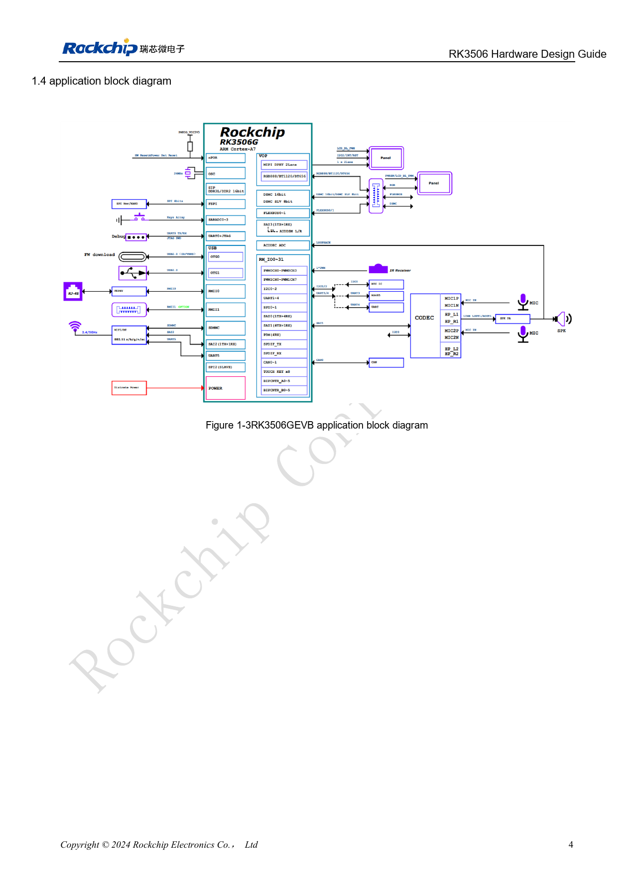
Chinese original; no matching English figure was found in the supplied materials. RK3506G EVB ≠ RK3506J / CM1 / Forge1. Reference design, not an ArmSoM board schematic.
RK3506 Hardware Design Guide_V1.0_20240904_CN.pdf · PDF p. 19.
Products and development resources
- CM1 — Product page · Documentation
- Forge1 — Product page · Documentation
Continue this series
- RK3576 hardware bring-up: minimum system and first-power checks
- ArmSoM CM5 carrier-board checklist: power, boot and interface planning
- RK3576 high-speed interfaces: review schematics and PCB together
- RK3588S hardware design: from a reference circuit to a CM7s carrier
- RK3588 edge-AI hardware: plan power, cooling and expansion together
- RK3588 high-speed PCB review: stackup, impedance and routing
- RK3308 hardware variants: compatibility checks for P2 Pro audio projects
- RK3588S versus RK3588S2: what to check before a hardware revision
- Rockchip prototype to production: process requirements and test records