
This article uses the specified datasheet revision. Values are vendor specifications, not ArmSoM measurements; no new hardware validation was performed. Check the actual silicon revision, board schematic, SDK/BSP, kernel and drivers. The explanations and editable tables assist reading; consult the original PDF for the complete specification and bit definitions not expanded here.
RK730 · Rockchip RK730 Datasheet V1.0-20241118.pdf · PDF 20–43.
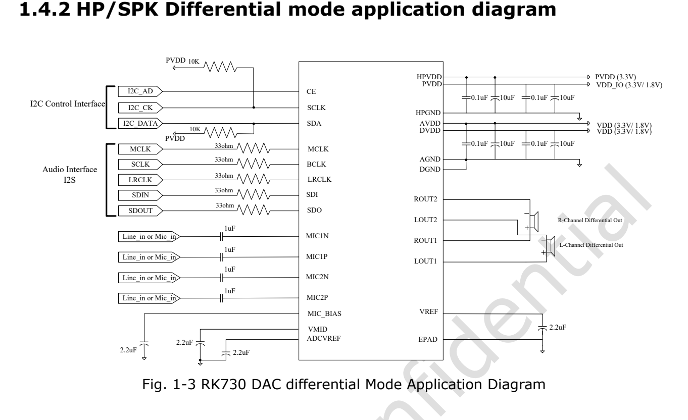
Original English figure, source PDF p. 10.
Bus address, register offset and bit field
CE selects the 0x16/0x17 I2C address; values such as 0x0000 below are register offsets. B means 8-bit data; four hexadecimal offset digits do not imply 16-bit data. Reset values are not initialized operating values. Check access attributes in the bit-field chapter and preserve address gaps rather than assuming every intermediate address is writable.
Complete register summary
| Register | Offset | Width | Reset value |
|---|---|---|---|
CODEC_HK_TOP_0 |
0x0000 |
B |
0x08 |
CODEC_HK_TOP_1 |
0x0001 |
B |
0xC0 |
CODEC_HK_TOP_2 |
0x0002 |
B |
0x00 |
CODEC_HK_TRIM |
0x0003 |
B |
0x00 |
CODEC_ADC_0 |
0x0004 |
B |
0x03 |
CODEC_ADC_1 |
0x0005 |
B |
0x42 |
CODEC_ADC_2 |
0x0006 |
B |
0x02 |
CODEC_ADC_3 |
0x0007 |
B |
0x05 |
CODEC_DAC_0 |
0x0008 |
B |
0x07 |
CODEC_DAC_1 |
0x0009 |
B |
0x70 |
CODEC_MIC_BOOST_0 |
0x000a |
B |
0x01 |
CODEC_MIC_BOOST_1 |
0x000b |
B |
0x01 |
CODEC_MIC_BOOST_2 |
0x000c |
B |
0x01 |
CODEC_MIC_BOOST_3 |
0x000d |
B |
0x01 |
CODEC_ADC_PGA_BLOCK_0 |
0x000e |
B |
0x01 |
CODEC_ADC_PGA_BLOCK_1 |
0x000f |
B |
0x01 |
CODEC_SYSPLL_0 |
0x0010 |
B |
0xff |
CODEC_SYSPLL_3 |
0x0013 |
B |
0x04 |
CODEC_LDO |
0x001f |
B |
0x11 |
CODEC_MIC_BIAS |
0x0020 |
B |
0x09 |
CODEC_HP_0 |
0x0021 |
B |
0xAC |
CODEC_HP_1 |
0x0022 |
B |
0x80 |
CODEC_HP_2 |
0x0023 |
B |
0x00 |
CODEC_SPK_0 |
0x0024 |
B |
0xAC |
CODEC_SPK_1 |
0x0025 |
B |
0x80 |
CODEC_DTOP_DIGEN_CLKE |
0x0040 |
B |
0x00 |
CODEC_DTOP_SRT |
0x0041 |
B |
0x00 |
CODEC_DADC_SEL |
0x0042 |
B |
0x00 |
CODEC_DDAC_SEL |
0x0043 |
B |
0x88 |
CODEC_DTOP_VUCTL |
0x0044 |
B |
0x03 |
CODEC_DTOP_VUCTIME |
0x0045 |
B |
0xFF |
CODEC_DADC_VOLL |
0x0046 |
B |
0x00 |
CODEC_DADC_VOLR |
0x0047 |
B |
0x00 |
CODEC_DDAC_VOLL |
0x0048 |
B |
0x00 |
CODEC_DDAC_VOLR |
0x0049 |
B |
0x00 |
CODEC_DADC_RVOLL |
0x004a |
B |
0xFF |
CODEC_DADC_RVOLR |
0x004b |
B |
0xFF |
CODEC_DDAC_RVOLL |
0x004c |
B |
0xFF |
CODEC_DDAC_RVOLR |
0x004d |
B |
0xFF |
CODEC_DADC_FILTER |
0x004e |
B |
0x1E |
CODEC_DDAC_FILTER |
0x004f |
B |
0xF4 |
CODEC_DDAC_PREL |
0x0050 |
B |
0x00 |
CODEC_DDAC_PRER |
0x0051 |
B |
0x00 |
CODEC_DDAC_POSTL |
0x0052 |
B |
0x1F |
CODEC_DDAC_POSTR |
0x0053 |
B |
0x1F |
CODEC_DDAC_DRC0 |
0x005e |
B |
0x9A |
CODEC_DDAC_DRC1 |
0x005f |
B |
0xCC |
CODEC_DDAC_DRC2 |
0x0060 |
B |
0x1F |
CODEC_DDAC_DRC3 |
0x0061 |
B |
0xCC |
CODEC_DDAC_DRC4 |
0x0062 |
B |
0x0E |
CODEC_DDAC_DRC5 |
0x0063 |
B |
0x08 |
CODEC_DDAC_DRC6 |
0x0064 |
B |
0x06 |
CODEC_DDAC_DRC7 |
0x0065 |
B |
0x02 |
CODEC_DDAC_DRC8 |
0x0066 |
B |
0x05 |
CODEC_DDAC_DRC9 |
0x0067 |
B |
0x01 |
CODEC_READ1 |
0x0068 |
B |
0x00 |
CODEC_DI2S_CKM |
0x0069 |
B |
0x01 |
CODEC_DI2S_OFFSET |
0x006a |
B |
0x00 |
CODEC_DI2S_RSD |
0x006b |
B |
0x00 |
CODEC_DI2S_RXCR1 |
0x006c |
B |
0x00 |
CODEC_DI2S_RXCR2 |
0x006d |
B |
0x17 |
CODEC_DI2S_RXCMD_TSD |
0x006e |
B |
0x00 |
CODEC_DI2S_TXCR1 |
0x006f |
B |
0x00 |
CODEC_DI2S_TXCR2 |
0x0070 |
B |
0x17 |
CODEC_DI2S_TXCR3_TXCMD |
0x0071 |
B |
0x00 |
Map the driver by control group
| Item | Specification / source note |
|---|---|
| HK_TOP / 0x0000–0x0003 | References, oscillator, bias and analog controls |
| ADC / 0x0004–0x0007 | Analog ADC power and controls |
| DAC / 0x0008–0x0009 | Analog DAC power and controls |
| MIC / PGA / 0x000a–0x000f | Microphone gain and preamplification |
| 0x0010 / 0x0013 / 0x001f | System PLL, PLL control, bias; non-contiguous |
| 0x0020–0x0025 | Headphone analog-output controls |
| 0x0040–0x0053 | Digital ADC/DAC, rate, volume and filtering |
| 0x005e–0x0071 | AGC, mixing and I2S; use only addresses in the summary |
Example: HK_TOP_0 is not a single byte-wide switch
| Item | Specification / source note |
|---|---|
| 0x0000[7] / [6] | VREF / OSC test controls |
| 0x0000[5:4] | VAG: 0x0=1.6 V; 0x1=1.52 V; 0x2=1.7 V; 0x3=1.8 V |
| 0x0000[3] | Oscillator enable; reset 1 |
| 0x0000[2] | Half-current mode control |
| 0x0000[1:0] | DAC chop: 0 / 200 / 400 / 800 kHz |
| 0x0001[7] / [6] | VAG / DAC-buffer power-down bits; reset 1 |
Using the reference correctly
Check access attributes before updating target bits through the driver’s masked-update logic, preserving other bits. Reset values from pages 20–21 do not replace full bit definitions on pages 21–43. Microphone gain encoding is not a uniform dB step; PLL, filtering and AGC also require their definitions. Compare register states after power reset, driver initialization and start/stop to locate which control layer changed state. No unverified whole-device write script is supplied.
ArmSoM products and application limits
CM1 and Forge1 are platform references for audio peripheral designs. This article does not claim an onboard RK730 or verified drop-in driver support. First check whether the required I2S, I2C, clocks and voltage levels are exposed.