
ArmSoM applicability and source scope
This is a Rockchip platform reference, not an ArmSoM hardware test report. The sole supplied source is Rockchip_Tuning_Guide_ISP30_EN_v1.2.0.pdf, V1.2.0, document RK-SM-YF-611, 160 pages. Its product table specifies RK3588 / ISP3.0. No Chinese source was supplied: Chinese and Russian fully translate this English source; all editions retain its original figures, some of which themselves contain Chinese labels. No kernel version is specified by the source. Confirm the exact ArmSoM board, RK3588 SDK/BSP, sensor and lens drivers, AIQ/IQ tool versions and calibration before adaptation. Board-specific compatibility and image-quality results have not been hardware-validated. All sample values and comparisons belong to the source, not ArmSoM measurements.
Source inconsistencies and incomplete formulas are preserved and documented in the editorial notes. They are not silently converted into validated guidance. Original chapter and figure numbers are retained even where duplicated or inconsistent.
Original product scope (PDF page 2)
| Chip | ISP version |
|---|---|
| RK3588 | ISP3.0 |
1 IQ debugging document relationship description
The use of this document is relevant to the following documents, which are summarized below:
Rockchip_Development_Guide_ISP30_: describes the user interface and its structure accordingly
Rockchip_IQ_Tools_Guide_ISP30_: Detailed instructions for using RK IQ Tools
Rockchip_Color_Optimization_Guide_ISP30: A detailed description of color tuning
The first chapter of this document mainly explains the document relationship description involved in the ISP tuning process, and the second chapter provides a system overview of ISP, including the functional block diagram of ISP and the introduction of each module; Chapter 3 mainly introduces the operation steps and precautions of the entire image tuning process. After Chapter 4, the debugging methods of each submodule are introduced into modules.
2 ISP system overview
1. 2.1 Introduction to the feature
The ISP30 module supports standard sensor image data processing, including basic functions such as auto white balance, auto exposure, Demosaic, dead pixel correction and lens shadow correction, as well as HDR, dehazing, noise reduction and other advanced processing functions.
2. 2.2 ISP functional block diagram
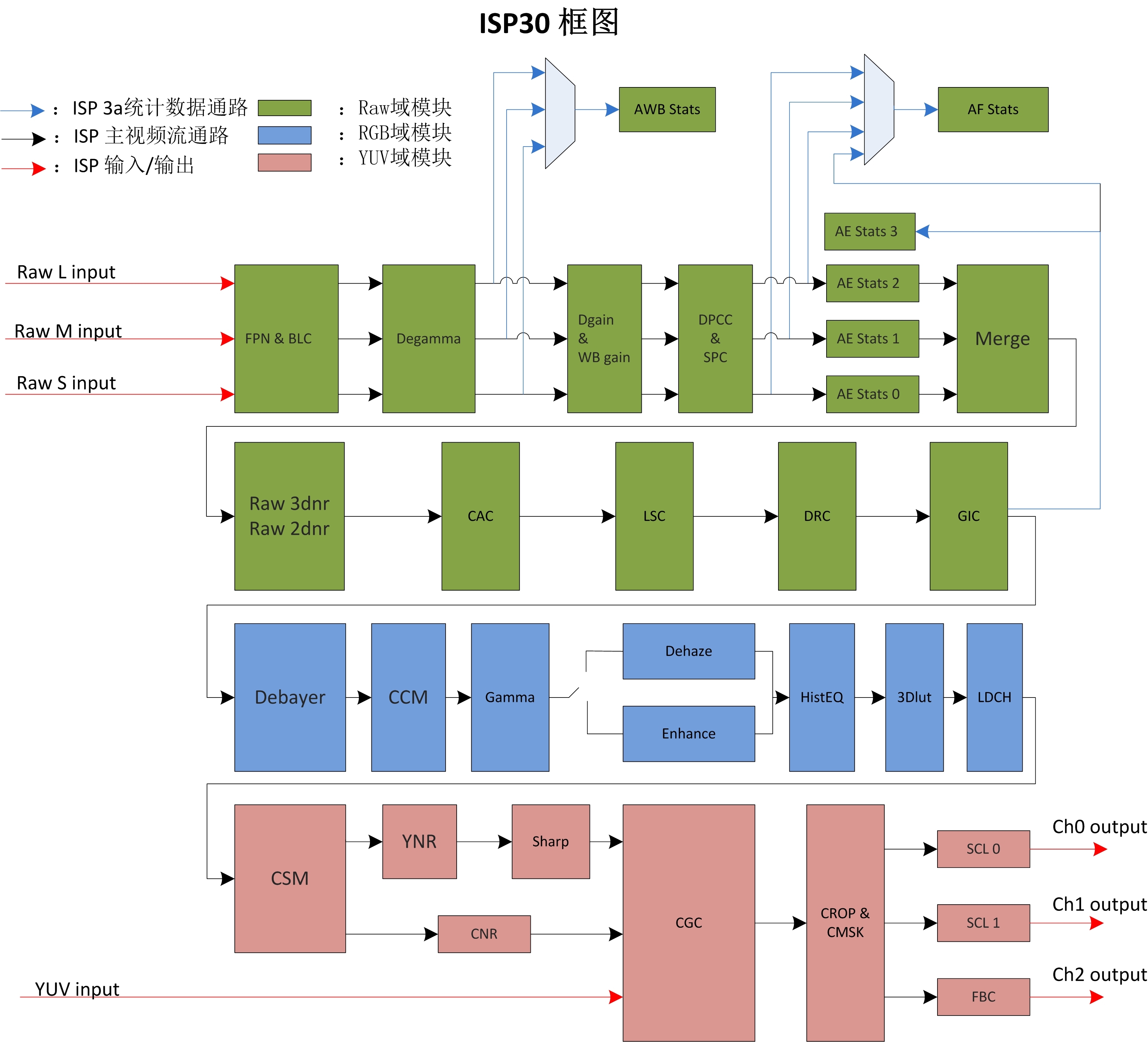
Figure 2-1 ISP30 functional block diagram
2.1 2.3 Introduction to each module
| Module name | Description |
|---|---|
| FPN | The CIS input image is corrected by the black frame or black line of the phenotype to remove fixed mode noise. |
| BLC | Provides CIS-related black level correction. |
| Degamma | CIS nonlinearization correction |
| DPCC | Provides detection and correction of static and dynamic dead pixels. |
| SPC | Provides correction of occluded pixels (phase focus) |
| Dgain | Provides digital linear gain |
| WB Gain | White balance correction gain |
| MERGE | 3-frame wide dynamic compositing. |
| Raw 3DNR & Raw 2DNR |
RAW domain time domain, space domain combined with noise reduction module |
| DRC | Dynamic Range Compression |
| GIC | Correct the imbalance between the two channels of Gr and Gb, and improve the image quality of some scenes |
| LSC | Used for shadow correction of lenses. |
| CAC | Corrects the axial chromatic aberration introduced by the lens (purple fringing) |
| AE Stats | This module outputs the statistical information of automatic exposure, and the software adjusts CIS according to the statistical information to realize the function of automatic exposure. |
| AF | Support image sharpness evaluation information statistics, used to complete the support autofocus function. |
| AWB | The module outputs global statistics and regional statistics, and the software completes the automatic white balance function based on the statistics |
| Debayer | Convert a Raw image in Bayer format to an RGB image |
| CCM | Linear correction of the color space can be accomplished by standard 3X3 matrix and vector offsets |
| Gamma | The module adjusts the brightness according to the gamma curve in three channels: R\G\B |
| Dehaze & Enhance |
Provides powerful dehaze capabilities to improve video contrast and clarity in haze scenes. |
| Module name | Description |
|---|---|
| CSM | The input (R, G, B) is converted to (Y, U, V) through the standard 3X3 matrix and vector offset, and the chroma downsampling output YUV422 is provided to the post- stage module |
| LDCH | Correct distortion in the vertical direction of the lens |
| 3D-LUT | The 9x9x9 size 3Dlut implements complex color adjustment operations, such as brightness adjustment, saturation adjustment |
| Sharp | YUV domain realizes image sharpness and improves image clarity |
| YNR | Airspace denoising for brightness |
| UVNR | Separate color noise removal. |
| CGC | YUV Color Space Conversion |
| CMSK | Provide image mosaic, occlusion function |
| FBC | Data compression |
| SCL | Image scaling |
3 Overall overview of image quality tuning
It is mainly oriented to two application scenarios, namely IPC security application scenarios and consumer application scenarios, among which IPC security application scenarios include linear mode and HDR mode; Consumer application scenarios mainly include sports DV, driving recorders, and capture products. Due to the special needs of the surveillance industry, IPC security application scenarios will focus on image quality differently from consumer application scenarios.
1. 3.1 Overview of IPC Application Image Tuning
For IPC application scenarios, it mainly includes two typical applications: linear mode and HDR mode. The image quality of linear mode mainly includes image brightness rationality, color reproduction accuracy, overall image clarity, overall sharpness and transparency. The image quality focus of HDR mode mainly includes the overall dynamic range of the image is reasonable (the bright areas are not exquisite, and the details in the dark areas can be seen), the color reproduction is as accurate as possible, and the overall clarity, sharpness, and transparency of the image. The following describes the debugging steps for image quality tuning for the two modes and the precautions for debugging the ISP single point algorithm.
1.1 3.1.1 Linear mode image quality tuning
The entire frame diagram of linear mode image tuning for the IPC application scenario is shown below (Figure 3-1):
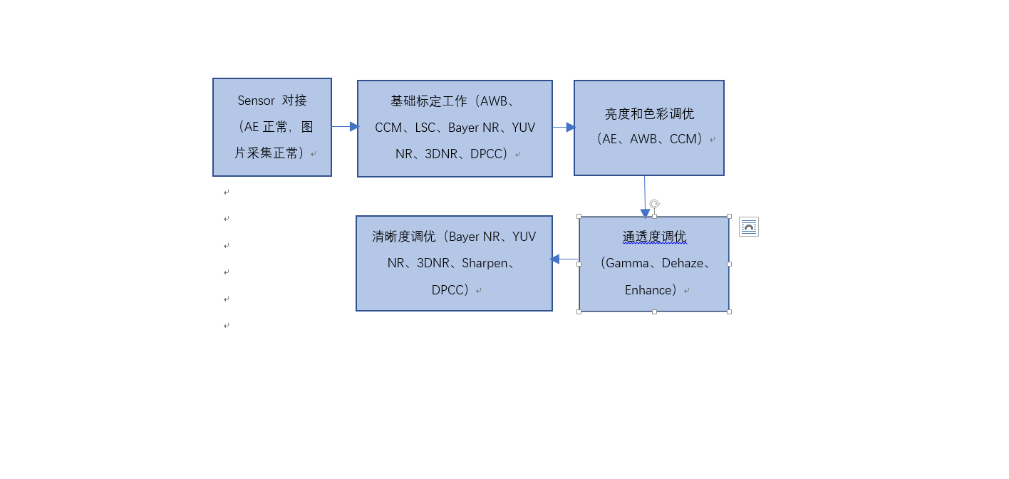
Figure 3-1 Linear mode image tuning flowchart for IPC application scenario
2. The main tasks that need to be done before image quality tuning are as follows:
1. sensor docking: According to the definition of the product, the CSI of the sensor is set, including frame rate, resolution, HDR mode, AE mode, and the initialization register sequence in each mode is mined according to the sensor datasheet or FAE provided by the manufacturer, and the initialization sequence is adapted to the MIPI configuration of the RK platform.
Completion standard: The docking mode path is normal, the AE basic working energy is normal, and RAW can be shot normally Rockchip_Driver_Guide_ISP2x.
2. Module calibration work: The calibration work mainly involves black level calibration, RawNR/YUV NR/3DNR calibration, static dead pixel calibration, lens shading calibration, AWB calibration, CCM calibration, lens distortion parameter calibration, etc. This calibration step needs to be carried out in strict accordance with the process shown in Figure 3-2:
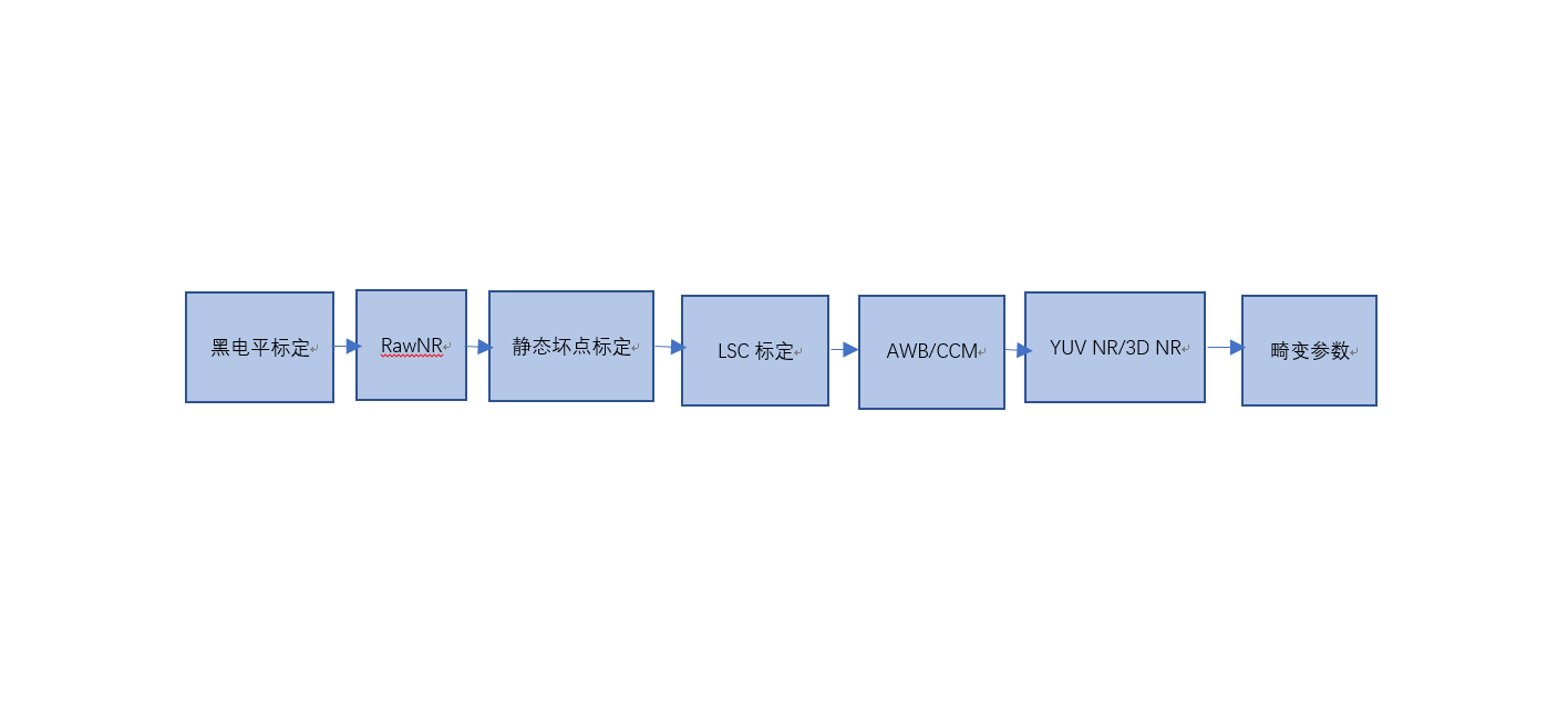
Figure 3-2 Module calibration flow chart
For the calibration details of each module, please refer to Chapter 4 for the details of the module introduction, and for AWB and CCM, please refer to Rockchip_Color_Optimization_Guide_ISP30
3. ISP module joint tuning: After completing the sensor docking and sensor lens calibration work, you can enter the ISP module joint tuning stage, linear image quality tuning includes multiple sets of ISO illuminance under the optimization of image quality, starlight level sensor generally needs to the highest ISO 204800, and ISO linkage BayerNR, Demosaic, sharpen, YUVNR, 3DNR, Dehaze, In addition to the open Mipi interface parameters of the enhanced and other algorithm modules, there are default parameters that will change according to the ISO linkage.
The scenarios of linear mode debugging mainly include laboratory static scenes and outdoor actual scenes, and generally use laboratory static scenes to simulate the scenes of each ISO, and then debug the brightness, color, transparency, clarity, and noise under each illumination level reasonably. Then, on this basis, it is necessary to fine-tune the actual scene according to the different application scenarios of IPC, and it is necessary to cover the day and night scenes of traffic intersections, outdoor night low-light scenes, outdoor daytime scenes with rich texture details, including sunny and cloudy weather, outdoor evening sunset scenes with rich texture textures, etc. Figure 3-3 shows the order of the tuning scenarios in linear mode.
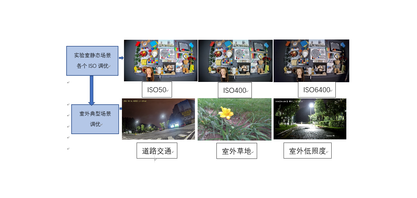
Figure 3-3 Linear mode image tuning scene graph
The basic flow of linear mode ISP image quality attention dimension debugging is shown in Figure 3-4.
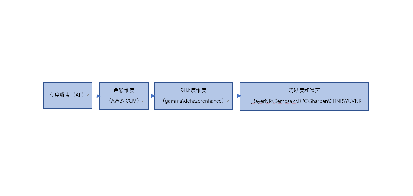
Figure 3-4 Image quality attention dimension debugging flowchart
Brightness dimension:
The main debugging module of the brightness dimension is AE, which mainly includes the tuning of the target value of AE, the tuning of AE Route, the tuning of the weight table of AE, and the tuning of convergence speed and smoothness of AE. The environment that needs to be prepared before adjusting AE: black level calibration is correct, Shading calibration is complete, AWB and CCM calibration are correct, a set of gamma parameters is preset for different modes, etc.
Step 1: The first step in AE tuning is to determine the weight table for AE. AE weight table determines the area of interest of AE exposure, different application requirements, AE weight table will also be different, generally for IPC application scenarios, the subject of the scene is the middle part of the picture, it is recommended to set the AE weight table in the middle part of the picture higher than the surrounding part. Figure 3-5 shows an example of an AE weight table:
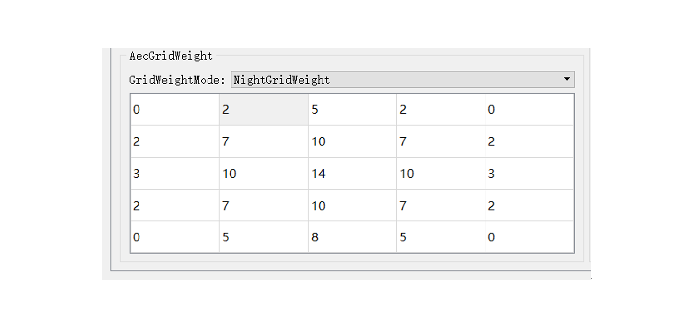
Editable transcription of the source screenshot: AecGridWeight, GridWeightMode: NightGridWeight.
| 1 | 2 | 3 | 4 | 5 |
|---|---|---|---|---|
| 0 | 2 | 5 | 2 | 0 |
| 2 | 7 | 10 | 7 | 2 |
| 3 | 10 | 14 | 10 | 3 |
| 2 | 7 | 10 | 7 | 2 |
| 0 | 5 | 8 | 5 | 0 |
Figure 3-5 AE weight table
Step 2: On the basis of determining the AE weight table, the next step is to determine the route of AE, which mainly determines the distribution method of exposure, that is, the distribution of exposure time and gain. Different scenes need to set different AE routes, such as need to pay attention to fast-moving objects, need to give priority to the use of gain and limit exposure time, such as daytime scene capture license plate, generally need to limit the exposure time to 2~4ms, at this time the exposure is prioritized on the gain, such as night low- illumination scenes, at this time in order to balance the noise performance of the picture, the exposure needs to be appropriately prioritized on the exposure time.
Step 3: On the basis of determining the AE weight and AE route, the next step is to adjust the target value of AE according to different exposures, for laboratory static scenes, the debugging standard of AE target value is that the highest area in the center of the picture is no obvious overexposure, as shown in Figure 3-6 static scene schematic diagram, the texture card in the middle, ceramic coffee cup can not be overexposed, corner dead leaf map and rose brightness is reasonable. The AE target value mainly involves SetPoint, DynamicSetpoint adjustment, and the selection of AE backlight mode.
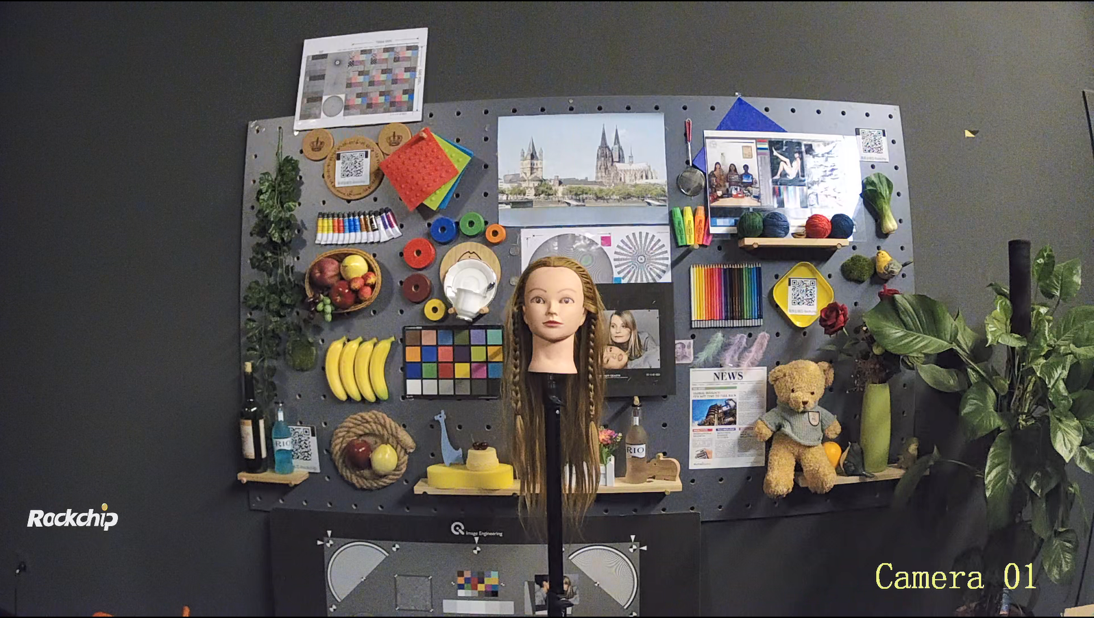
Figure 3-6 Schematic diagram of static scene
Step 4: Finally, you need to adjust the convergence speed and AE smoothness of AE, AE convergence speed and AE smoothness are a pair of balance points. Under the premise of preventing AE oscillation, it is possible to appropriately increase the convergence speed of AE, especially for driving recorders and sports DV application scenarios, and it is necessary to appropriately increase the AE convergence speed to adapt to the drastic changes of the scene. The convergence speed and convergence stability of AE can generally be tested by switching lights in laboratory still life scenes.
For specific parameter adjustment of AE module, please refer to the description chapter on AE in the AE module introduction of this document. It should be noted that the LSC module also affects the brightness of the image, so LSC recommends linkage attenuation according to ISO to avoid noise that will cause vignetting of the image to become larger in the case of slightly lower illumination.
—-Come to an end
Color dimension:
On the basis of reasonable AE adjustment, the next main adjustment of color-related parameters, mainly involved modules are AWB and CCM. The environment that needs to be prepared before color: accurate black level correction, LSC calibration completed, and reasonable debugging of AE module parameters.
Step 1: In the laboratory lightbox scene, you need to capture the raw calibration of seven groups of 24 color cards at different color temperatures (D75, D65, D50, TL84, CWF, A, HZ) to obtain the AWB static white balance coefficient and generate a white balance white point condition box. For details, please refer to Subsection 4 of Chapter 4 of Rockchip_IQ_Tools_Guide_ISP30.
Step 2: Using the RAW diagram for AWB calibration, use the tool to generate the CCM matrix at the saturation of the corresponding light source.
Before that, you need to confirm the gamma curve used, generally default gamma 2.2, if you have special requirements for gamma, you need to fill in the gamma curve first. The operation interface reference is as follows:
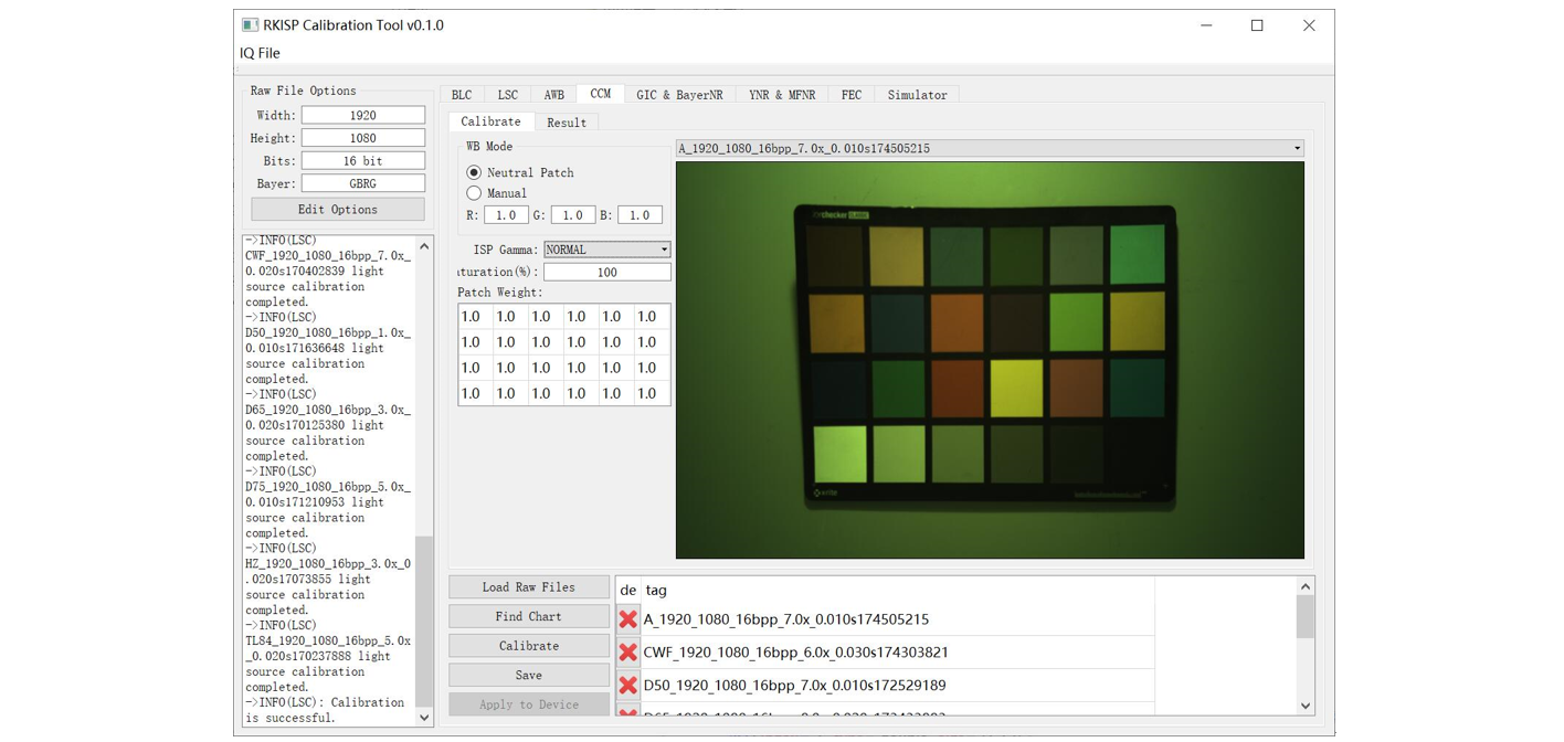
Figure 3-7 CCM calibration interface
Step 3: After completing steps 1 and 2, we can take 24-color card pictures of each light source in the standard light box, and test the color indicators of the 24-color card with imatest software. If the indicators meet the requirements, the AWB parameters and CCM matrix obtained by calibration can be preliminarily determined to meet the requirements.
Step 4: The parameter rationality of AWB and CCM modules also requires a lot of testing and debugging of practical application scenarios. Typical practical application scenarios include typical outdoor scenes, including front light, backlight, cloudy days, sunset, night, and mixed light sources. If there are gray blocks in the scene and the restoration is inaccurate, you need to adjust the AWB parameters, and some colors in the scene are color-cast, oversaturated or light, we recommend that you prioritize the parameters of CCM. For mixed light source application scenarios, you need to adjust the scene detection parameters in AWB, and if the skin tone of the characters in the actual scene is not accurately restored, you need to adjust the CCM parameters or 3Dlut parameters.
For specific tuning of AWB and CCM modules, refer to Rockchip_Color_Optimization_Guide_ISP30
—-Come to an end
Contrast dimension
On the basis of the reasonable brightness dimension and color dimension, the next step is to optimize the contrast dimension. The modules that affect the contrast mainly include Gamma, Dehaze, Enhance, etc., and the general focus is on Gamma parameter adjustment in different scenarios, and Dehaze and Enhanced are auxiliary modules.
Prepare environment before adjusting contrast: black level correction is correct, LSC calibration is complete, AE exposure adjustment is reasonable, AWB and CCM parameters are reasonably calibrated.
Step 1: Adjust gamma parameters, which are the basic modules of image image contrast, taking static real scenes as an example, by adjusting Gamma parameters, the skin tone card in the middle of the picture and the light and dark textures of the edge three-dimensional plants are not lost, and the contrast visual experience of the picture is better. The following figure is shown.
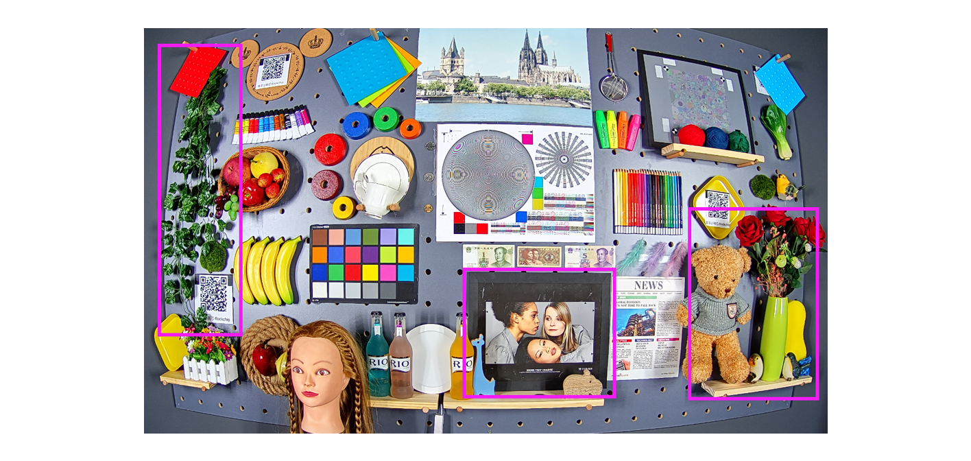
Figure 3-8 Example of an area affected by a gamma curve in a static scene
Step 2: On the basis of adjusting the Gamma parameters, if you have higher requirements for the contrast of the image, you can adjust Dehaze or Enhanced to improve the contrast. For tuning instructions for Dehaze and Enhance, see sections 4.21 “Dehaze” and 4.22 “Enhance”. Step 3: On the basis of optimizing the contrast related parameters, it is necessary to objectively test the overall contrast effect, test the grayscale card in the D65 light source environment, observe whether the gray order can reach more than 18 steps, and test whether it can reach 14steps with imatest.
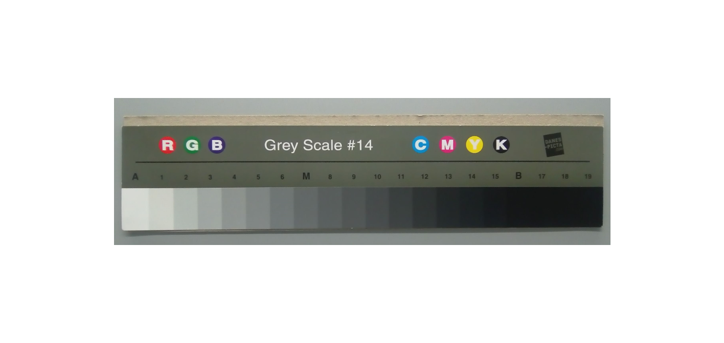
Figure 3-9 Example grayscale card in the environment of D65 light source in the laboratory lightbox and imatest analysis results
Step 4: In the actual static scene, you need to adjust Gamma, Dehaze, Enhance and other parameters according to different applications and different illuminance to achieve contrast balance in each scene. Of course, under normal illumination and low illumination, there will be certain differences in contrast debugging styles, such as night mode, Gamma will appropriately lower the dark area to reduce the burden of dark area noise.
—-Come to an end
Clarity and noise dimension
Clarity and noise is a pair of balance points, due to different illuminance, the noise performance of the image is also different, normal low illumination, the noise of the picture will be more serious, very affect the visual experience, so we will appropriately sacrifice the requirements of clarity, so the parameters of clarity and noise need to be controlled according to different ISO scenes.
For the debugging of clarity and noise dimension, it is recommended to give priority to clarity first, and show the sharpened details before noise reduction, if debugging in the actual on-demand environment, you need to set the encoding bitrate high and the 3DNR level to the minimum, and observe whether the details of the still picture are sharpened. Under the premise that the clarity meets the requirements, the noise reduction module is debugged to finally achieve the balance between clarity and noise.
Adjust the sharpness and noise preparation environment: black level correction is correct, LSC calibration is completed, AE exposure adjustment is reasonable, AWB and CCM parameter calibration is reasonable, Gamma/Dehaze/Enhance and other adjustments are reasonable.
Modules that affect clarity and noise mainly include Bayer NR, Demosaic, DPCC, YNR, UVNR, 3DNR, sharpen, Edgefilter, etc.
Step 1: The first threshold for basic texture detail in an image is Demosaic. Before debugging the module, we need to confirm that the black level calibration is accurate, the RawNR calibration is reasonable, and the AWB/CCM calibration is reasonable.
First of all, we need to debug the Demosaic parameter against the resolution card under the D65 light source in the laboratory lightbox environment under the ISO50 light source, so that the resolution of the resolution card meets the objective index requirements, and at the same time, we need to check whether the high-frequency texture of the star map in the static scene can be interpolated in the ISO50 environment, so as to iterate back and forth. The other ISOs then need to be debugged in the same way to balance the high-frequency noise with the noise from the interpolated values and whether the clarity is appropriate. Figure 3-10 shows a schematic diagram of a resolution card in the environment of the D50 light source. The red frame is for the 4:3 field of view, and the basket frame is the center area of interest. For specific debugging methods of Demosaic, please refer to section 4.4 “Demosaic”.
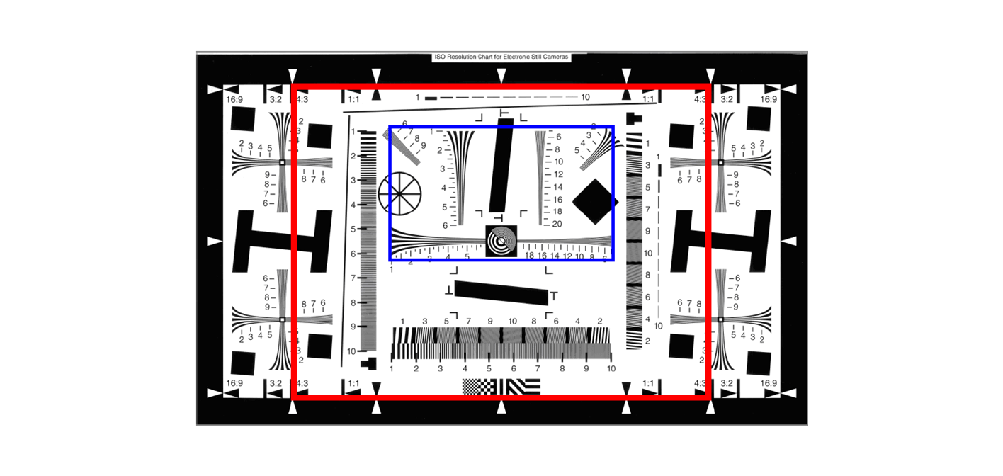
Figure 3-10 Schematic diagram of the clarity card in the environment of the laboratory light box D65 light source
Step 2: After the parameters of Demosaic are properly debugged, the next step is to focus on the BayerNR, YNR, UVNR, 3DNR and Sharpen and DPCC modules.
Before debugging the Bayer NR module, confirm that the black level calibration is accurate, the RawNR calibration is reasonable, and the AWB/CCM calibration is reasonable.
Bayer NR, as the front-stage noise processing module, should not open the intensity too large, otherwise the clarity of the picture will be lost. For specific tuning methods of Bayer NR, please refer to section 4.5 “Bayer NR”.
Step 3: YNNR and UVNR are the noise reduction modules that need to be debugged, for the high-frequency, low- frequency, and medium-frequency noise of the picture, YNR can independently control the intensity of the force, and UVNR is used to remove color noise, and its intensity does not affect the clarity, but excessive force will lead to color distortion. For specific tuning methods of YNNR and UVNR, please refer to Section 4.6 “YNNR and UVNR”.
Step 4: The debugging criteria of sharpen and Edgefilter mainly adjust the texture details and edge sharpness of the image to the appropriate, taking the laboratory static scene as an example, sharpen and Edgefilter two modules need to sharpen the details of the still life scene such as green vine, green algae, bear and hemp rope before the image passes through 3DNR, and also sharpen the strong edges such as the circle star map in the center. The following figure is shown. For specific tuning methods of sharpen and edgefilter, please refer to section 4.7 “sharpen and edgefilter”.
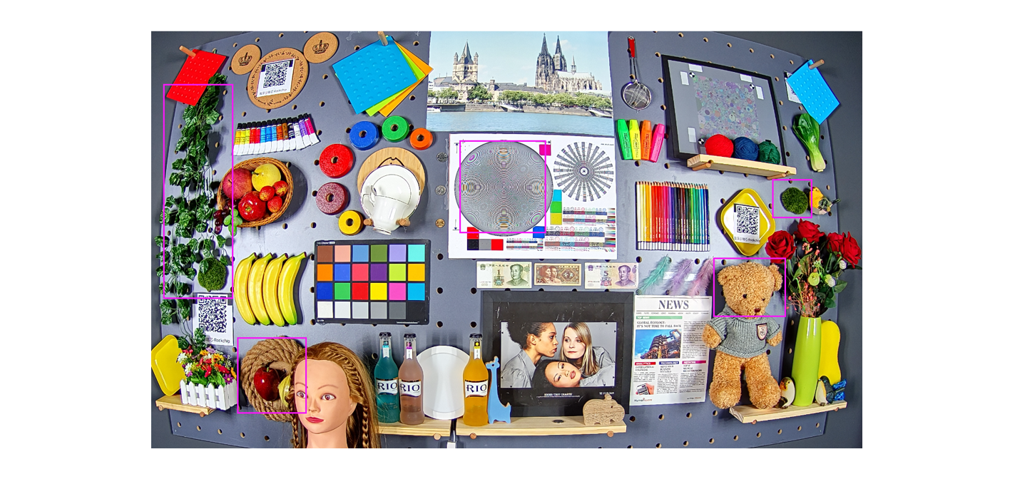
Figure 3-11 Static scene ISO50 needs to focus on sharpened texture schematic
Step 5: DPCC de-dynamic dead pixel intensity only needs to be confirmed clearly in scenes with slightly lower illumination. Scenes with good illumination suggest that the DPCC level is weak. For specific debugging methods of DPCC, please refer to Section 4.8 “DPCC”.
Step 6: 3DNR is the key point in the overall balance between noise and sharpness, mainly including DEC, REC and NR adjustment. The module breaks down the noise into different frequency bands, removes them separately, and then fuses them. When optimizing 3DNR, we should pay attention to the edges of moving objects, the degree of smearing of moving objects, and the acceptability of overall noise. As shown in the red frame of the figure below, the motion blur state of the character and the overall noise need to be balanced. For specific debugging methods of 3DNR, please refer to Section 4.9 “3DNR”.
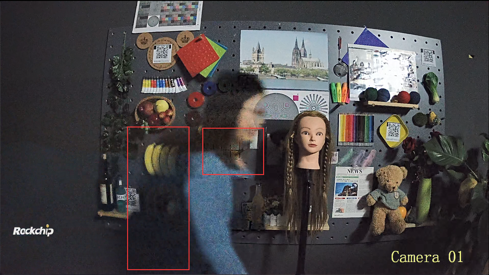
3-12 Schematic diagram of 3DNR test points
Step 7: After the above steps are completed, the final effect needs to be tested comprehensively under each ISO, and fine-tuning needs to be made when necessary to achieve the overall clarity and noise balance.
—-Come to an end
1.2 3.1.2 HDR mode image quality tuning
For HDR mode, image quality mainly focuses on the following dimensions: dynamic range, brightness, clarity and noise, transparency, color reproduction, and sports tailing performance, among which the modules involved in brightness mainly include AE and LSC; The dynamic range mainly depends on the exposure ratio control, and the modules mainly involved in sharpness and noise are Bayer NR, Demosaic, DPCC, YNR, UVNR, 3DNR, sharpen, Edgefilter, etc.; Permeability mainly affects modules such as Gamma, Dehaze, Enhance, etc.; Color reproduction involves modules such as AWB, CCM, and 3DLUT; The severity of a sports tail depends on the control and exposure ratio of the HDR parameters. Most of the typical application scenarios of HDR include face acquisition under backlight or license plate acquisition under strong light. The entire architecture diagram of HDR mode image tuning is shown in Figure 3-13.
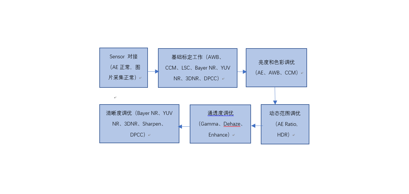
3-13 HDR mode image tuning architecture diagram
Before HDR mode image quality tuning, it is necessary to dock the sensor and calibrate the lens module, and the sensor docking steps can refer to the explanation of the sensor docking in summary 3.1.1. In the calibration of lens modules, AWB, Shading, Bayer NR and other modules can refer to the parameters of linear mode calibration, if the HDR mode of the sensor is HCG/LCG mode, it is necessary to follow up different modes to calibrate Bayer NR, YUV NR, 3DNR and other modules. Since CCM is after HDR TMO, the TMO module destroys the linear relationship of data, so CCM in HDR mode needs to make appropriate adjustments:
1. The saturation calibration value is about 80%~90%;
2. If individual colors appear abrupt, you can fine-tune them with 3D lut.
3. Appropriately reduce the TMO module’s greatly improved brightness and reduce the impact on color reproduction. When the brightness is insufficient, you can consider using the Gamma module to co-debug with HDR TMO.
After completing sensor integration and sensor/lens calibration, the next step optimizes the dimensions of image quality in HDR mode.
HDR backlit scene to enhance face brightness application scenario debugging guide
1. Brightness dimension:
HDR brightness dimension, here mainly refers to the rationality of AE exposure, mainly through debugging the AE module, AE module has HDR AE and linear AE two sub-control modules. Part of the difference between HDR AE and linear AE is that it mainly adjusts the exposure ratio of AE to determine the exposure time of long and short frames. Other parameters of AE include AE weight table, AE route, AE target value, and AE convergence speed and smoothness, which can be referred to the brightness dimension subsection of 3.1.1 “Linear Mode Image Quality Tuning”.
The exposure ratio of HDR AE determines the dynamic range of HDR mode images, so HDR mode is used for different scene dynamic ranges, and the exposure ratio of HDR AE needs to be adjusted adaptively. The mode of HDR AE exposure ratio supports the automatic exposure ratio mode, the so-called automatic exposure ratio, that is, HDR AE will automatically calculate the dynamic range of the scene according to the histogram of the scene to get a reasonable exposure ratio, the rationality of the exposure ratio is reflected in the bright area details are not exposed and the long frame brightness is reasonable. HDR AE uses long frame exposure as a benchmark and determines short frame exposure by exposure ratio.
In HDR mode, short-frame images are preferred for bright areas and long-frame images are used for dark areas. In a backlit scenario, the face is in the dark area of the scene, and the steps to improve the brightness of the face are as follows:
1. Improve the brightness of long frame images by adjusting AE parameters including weight table, AE route, AE long frame target value, etc.
2. Improve the brightness of dark areas by adjusting HDR TMO module parameters, including DetailsLowLight.
3. By limiting the maximum exposure ratio, the dynamic range of the image is controlled, which will also slightly increase the brightness of the dark areas to some extent.
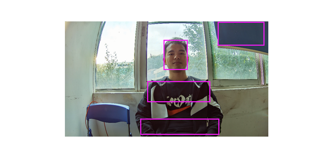
3-14 Schematic diagram of dark areas in long frames
1. Motion smearing dimension of the composition area:
HDR mode affects images in the compositing area from long and short frames, respectively. In principle, motion smearing is caused by the time difference between the exposure time of long frames and short frames, and the movement of image content. The exposure ratio of the main HDR module and HDR AE is adjusted for this dimension, and the larger the exposure ratio, the greater the probability of motion smearing in the composite area.
1. Take into account the dynamic range of the scene and motion smearing, and debug the HDR AE exposure ratio reasonably.
2. Under the same exposure ratio condition, reduce the exposure delay of long and short frame times by adjusting the exposure time of short frames, and then reduce the degree of smearing.
3. Reduce the probability of misusing short frames in the composition area due to motion by adjusting the OECurve_XXX and MDCurve_XXX parameters of the HDR MERGE module, thereby reducing the situation of motion tailing.
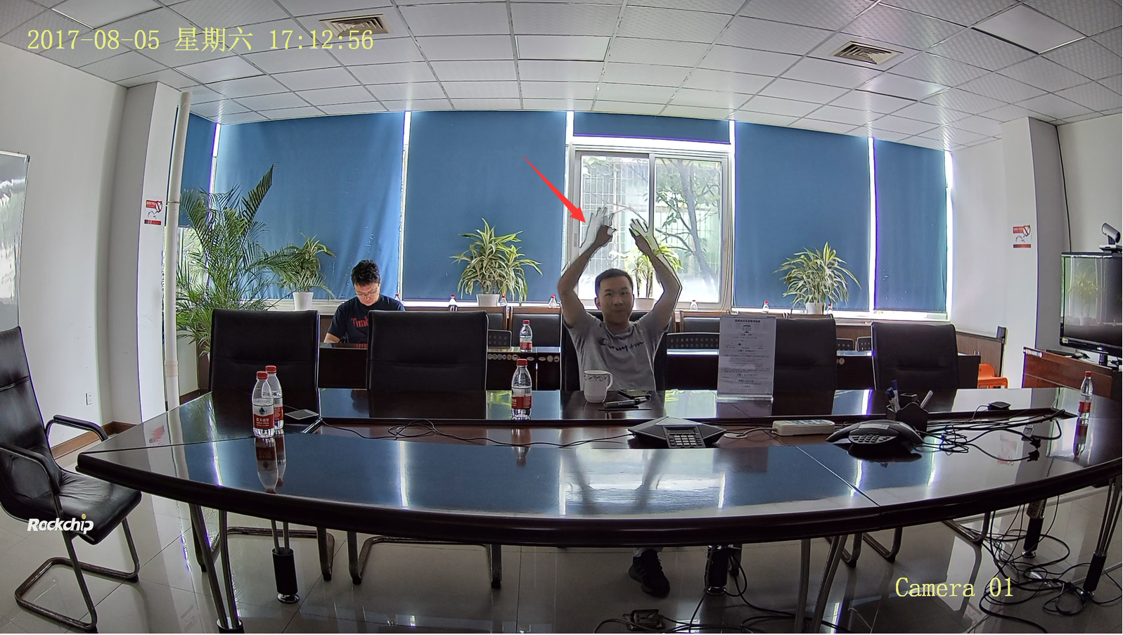
3-15 HDR composite area motion tailing diagram
Scene dynamic range dimension:
HDR mode affects image dynamic range including: AE’s exposure ratio, HDR DRC module, and Gamma module. Debug the entry conditions of the DRC module: correct black level calibration, Shadimng calibration completed, reasonable debugging of AE module, complete AWB and CCM calibration, preset a set of Gamma parameters.
As shown in Figure 3-14, a similar scene is arranged in a separate box, a lux meter is put in, and dimmable LED fill lights are placed at 45 degrees on both sides of the box, so that scenes with different dynamic ranges can be simulated.
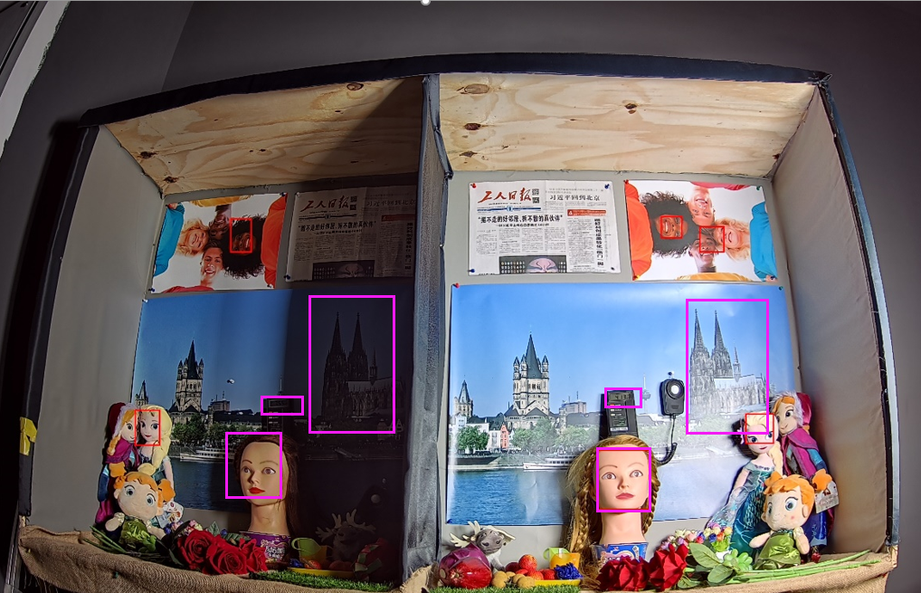
3-14 Dynamic range tuning scenario
Color dimension:
Please refer to the color debugging method in linear mode; Note that due to the Tonemap in HDR mode, the color performance is slightly different from linear, and it is recommended to reduce the saturation appropriately according to the situation after calibration.
Contrast dimension:
Please refer to the contrast debugging method in linear mode;
Clarity and noise dimensions:
Please refer to the sharpness and noise debugging method in linear mode;
4 Module introduction
This chapter mainly introduces the functions of each module and parameter description, in which the parameters are stored in firmware as XML files, and some parameters can be debugged with debugging tools. The parameter description format in this section is briefly described as follows:
” “ : Indicates that the parameter is in string form
xxx/yyy: Represents the yyy element entity in the xml file is a xxx child element entity
1. 4.1 AEC
1.1 4.1.1 Feature description
The AE module is mainly composed of two parts: the metering statistics module and the AE control algorithm module. The metering statistics module enters the brightness statistics for the AE control algorithm module, and the luminance statistics include histogram statistics and block average brightness statistics. The statistics mainly include the following parts: 256-segment weighted histogram statistics based on RAW graph, R/G/B/Y mean statistics based on RAW plot; 32-segment weighted histogram statistics based on gamma pre-RGB plot, and chunked R/G/B/Y mean statistics based on gamma pre-RGB plot.
The AE control algorithm module compares the input luminance statistics value with the target brightness, calculates the new exposure, and finally automatically assigns the sensor exposure time, exposure gain and lens aperture value to obtain an image of suitable brightness.
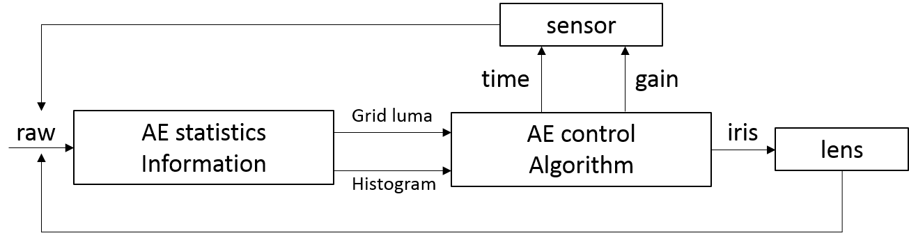
Figure 4-1 AEC module schematic
1.2 4.1.2 Key parameters
The parameters of the AEC module are roughly divided into public function control parameters, linear exposure debugging parameter modules, and HDR exposure debugging parameter modules according to functions. In addition, this section will also introduce the system parameters SensorInfo parameters and System parameters related to exposure, and their specific functions are detailed in the module description.
1.2.1 4.1.2.1 AEC module common function control parameters
| Parameter name | Parameter type | Brief description |
|---|---|---|
| Enable | Debug parameters | User debugging parameters |
| AecRunInterval | Debug parameters | User debugging parameters |
| AecOpType | Debug parameters | User debugging parameters |
| HistStatsMode | Debug parameters | User debugging parameters generally use the default value |
| RawStatsMode | Debug parameters | User debugging parameters generally use the default value |
| YrangeMode | Debug parameters | User debugging parameters generally use the default value |
| AecSpeed | Debug parameters | User debugging parameters |
| AecDelayFrmNum | Debug parameters | User debugging parameters |
| AecFrameRateMode | Debug parameters | User debugging parameters |
| AecAntiFlicker | Debug parameters | User debugging parameters |
| AecGridWeight | Debug parameters | User debugging parameters |
| AecManualCtrl | Debug parameters | User debugging parameters |
1.2.1.1 Enable
【Description】
AEC module switch function. 0: Close; 1: Open
【Notes】
When the Enable value is 0, the AEC algorithm is turned off. The exposure remains at the value before it turned off.
1.2.1.2 AecRunInterval
【Description】
The AE algorithm runs at a value range of [0,255], and the default value is 0. If the value is 0, run AE every frame; If the value is 1, run AE every 1 frame; And so on.
It is recommended that this value should not be too large, otherwise it may cause slow and unsmooth AE response
1.2.1.3 AecOpType
【Description】
Exposure modes, divided into auto exposure (RK_AIQ_OP_MODE_AUTO) mode / manual (RK_AIQ_OP_MODE_MANUAL) exposure mode.
Manual exposure mode needs to be used in conjunction with AecManualCtrl to set the manual exposure value.
The AecManualCtrl parameters are detailed below.
1.2.1.4 HistStatsMode
【Description】
AEC module histogram statistical mode. There are five modes: CAM_HISTV2_MODE_Y/R/G/B/RGB, and the default is Y mode.
1.2.1.5 RawStatsMode
【Description】
AEC module luminance statistics mode. There are four modes: CAM_RAWSTATSV2_MODE_Y/R/G/B, and the default is Y mode.
1.2.1.6 YrangeMode
【Description】
Aec module Y-channel Range mode. The two modes are CAM_YRANGEV2_MODE_FULL/LIMITED, and the default is FULL mode.
This parameter is only valid when RawStatsMode is in Y mode.
1.2.1.7 AecGridWeight
【Description】
Count the weights of each subwindow of the main window, including 15x15 parameters
【Notes】
The 3588 platform hardware can support the weight setting of 5X5 and 15X15 specifications, and the weight of 15X15 is uniformly set in the debugging file, and the weight is compressed or expanded according to the actual hardware configuration within the algorithm.
1.2.1.8 AecWinScale
【Description】
AE module hardware statistics window size ratio configuration parameters
【Member】
| Member name |
description |
|---|---|
| InputRaw | The AE hardware statistics window size ratio configuration parameter based on the raw graph contains a total of 4 parameters, corresponding to [h_off,v_off,h_size,v_size], and the range=[0,1] of each parameter |
| TmoRaw | The AE hardware statistics window size ratio configuration parameter based on the raw graph after the TMO module contains a total of 4 parameters, corresponding to [h_off, v_off, h_size, v_size], and the range=[0,1] of each parameter |
| Yuv | The AE hardware statistics window size ratio configuration parameter based on yuv diagram contains a total of 4 parameters, corresponding to [h_off,v_off,h_size,v_size], and the range=[0,1] of each parameter |
【Notes】
The window size ratio configuration parameter is based on the sensor resolution, set the corresponding scale value, where the scale configuration parameter range=[0,1]. The h_off and v_off represent the horizontal and vertical offset values of the upper left corner of the hardware statistics window relative to the sensor- sensitive area, respectively. The h_size and v_size represent the horizontal and vertical dimensions of the hardware statistics window, respectively.
The resolution of the sensor is expressed in res, and the actual configured hardware window offset value is [res x h_off, res x v_off]; The actual configured hardware window size value is [res x h_size, res x v_size].
The sum of the offset value and size value of the hardware window cannot exceed 1, that is, the requirement is h_off + h_size <=1, v_off + v_size <=1.
1.2.1.9 AecManualCtrl
【Description】
Manual exposure parameter setting, according to the exposure mode is divided into LinearAE and HdrAE two sets of parameters.
【Member】
| Member name | Description |
|---|---|
| ManualTimeEn | Manual exposure time enabled, default value is 1 |
| ManualGainEn | Manual exposure time enabled, default value is 1 |
| ManualIspDgainEn | Manual ISP digital gain enabled, default value is 1 |
| TimeValue | Manual exposure time values, in s, parameter values limited by sensor |
| GainValue | Manual sensor gain value, where the gain value is the actual value in units of 1x, and the parameter value is limited by the sensor |
| IspDGainValue | Manual ISP digital gain value, where the gain value is the actual value, the unit is 1x, and the parameter value is limited by the ISP |
【Notes】
This module only works when AeOptype = MANUAL. ManualTimeEn, ManualGainEn, ManualIspDgainEn are all 1, which is manual mode; As long as any of the above three is not enabled, it is semi-automatic mode; If all three of the above are 0, it is equivalent to automatic mode, and the system will report an error reminder.
In manual/semi-manual mode, the manual exposure time and gain are limited by the maximum/minimum exposure time and gain in automatic mode. After the auto exposure limit is exceeded, the maximum/minimum value in auto mode is used instead.
The 3588 platform does not currently support ISP digital gain, so ManualIspDgainEn, IspDGainValue are invalid.
1.2.1.10 AecSpeed
【Description】
Auto exposure adjusts the speed attribute.
【Member】
| Member name | Description |
|---|---|
| DyDampEn | Dynamic adjustment speed switch is on: the exposure adjustment speed is dynamically adjusted with the brightness of the scene, and off: the exposure adjustment speed is fixed with the DampOver/DampUnder/DampDark2Bright/DampBright2Dark value |
| SmoothEn | Smooth switch On: Enables exposure smoothing Off: Turns off exposure smoothing to increase exposure adjustment |
| DampOver | The ambient brightness is stable, and the corresponding exposure adjustment speed when the image brightness is higher than the target value, the value range [0,1] |
| DampUnder | The ambient brightness is stable, and the corresponding exposure adjustment speed when the image brightness is lower than the target value, the value range [0,1] |
| DampDark2Bright | Sudden change in ambient brightness, corresponding exposure adjustment speed from dark to light, value range [0,1] |
| DampBright2Dark | Sudden change in ambient brightness, corresponding exposure adjustment speed from light to dark, value range[0,1] |
【Precautions】
Automatic exposure adjustment damping coefficient, by adjusting the weight of the current exposure value and the current exposure value, to achieve the adjustment of the exposure speed. Final exposure value = current exposure value x DampCoef + new exposure value x (1 - DampCoef )
The greater the damping factor of the AE adjustment, the slower the exposure adjustment and vice versa. In order to ensure a smooth adjustment process, it is recommended to set the adjustment speed within the range of [0.4, 0.7].
Use DampDark2Bright/DampBright2Dark as the speed adjustment damping coefficient when the ambient brightness changes abruptly (dark becomes brighter/light becomes darker); When the ambient brightness is stable, DampOver/DampUnder is used as the speed adjustment damping coefficient during AE convergence. It is recommended that the DampDark2Bright/ DampBright2Dark value is less than DampOver/DampUnder, the DampDark2Bright value is less than DampBright2Dark, and the DampOver value is less than DampUnder.
1.2.1.11 AecDelayFrmNum
【Description】
Auto exposure triggers the time-lapse property
【Members】
| Member name |
Description |
|---|---|
| BlackDelay | The auto exposure triggers the time-lapse property, and when the image brightness is lower than the target value and exceeds the BlackDelay frame, Ae starts to adjust |
| WhiteDelay | The auto-exposure triggers the time-lapse property, and when the image brightness is higher than the target value and exceeds the WhiteDelay frame, Ae starts to adjust |
【Precautions】
BlackDelay/WhiteDelay should not be too large, otherwise the AE trigger response will be too slow.
1.2.1.12 AecFrameRateMode
【Description】
Auto exposure frame rate mode, which can be divided into fixed frame rate mode and automatic frame reduction mode
【Members】
| Member name |
Description |
|---|---|
| isFpsFix | The default value of the fixed frame rate mode is 0, that is, the automatic frame rate mode is used, and the value of 1 is the fixed frame rate mode. |
| FpsValue | Valid only in fixed frame rate mode, the default frame rate of the driver is used when the default value is 0, and the set frame rate value is used when the value is not 0. |
【Precautions】
Fixed frame rate mode: isFpsFix must be enabled. If the FpsValue is 0, the default frame rate in the driver is used, and if the value is not 0, the set frame rate value is used. In fixed frame rate mode, the maximum exposure time will be determined by both the frame rate and the maximum exposure time set in AecRoute. When the maximum exposure time set in AecRoute exceeds the limit of the current fixed frame rate, the algorithm will correct the maximum exposure time.
Auto Frame Downgrading: isFpsFix is set to 0, and the FpsValue value is invalid. The minimum frame rate of the Auto Frame Down mode is determined by both the maximum exposure time in AecRoute and the CISMinFps in SensorInfo. When the maximum exposure time in AecRoute exceeds the maximum exposure time allowed by CISMinFps, the value will be corrected internally by the algorithm. After the current exposure is decomposed, if the exposure time is greater than the exposure time allowed by the driver’s default frame rate, the vblank value will be modified to reduce the frame rate and increase the exposure time, and if the exposure time is less than or equal to the exposure time allowed by the driver’s default frame rate, the current frame rate will be set to the driver’s default frame rate. The specific implementation of automatic frame downing depends on the AecRoute parameter, setting the gain threshold in AecRoute, and triggering the frame downgrade when the gain is greater than the threshold.
1.2.1.13 AecAntiFlicker
【Description】
Auto exposure anti-power frequency flicker property
【Members】
| Member name |
Description |
|---|---|
| enable | The anti-power frequency flicker function is enabled, when the value is 1, the anti-power frequency flicker function is turned on, and vice versa. |
| Frequency | Set the power frequency in two types: AECV2_FLICKER_FREQUENCY_50HZ and AECV2_FLICKER_FREQUENCY_60HZ |
| Mode | Anti-power frequency flicker working mode, a total of two modes: AECV2_ANTIFLICKER_NORMAL_MODE mode, AECV2_ANTIFLICKER_AUTO_MODE mode. Through different working modes, the exposure time is adjusted to achieve anti-power frequency flicker |
【Precautions】
When enable is 0, the anti-flash function is turned off.
NORMAL anti-flash mode: Minimum exposure time and exposure time adjustment step fixed to 1/120 s (60Hz) or 1/100 s (50Hz). Therefore, in a high-brightness environment, overexposure may occur. In a lit environment, the exposure time can be matched to the frequency of the light source, which can prevent the image from flickering
AUTO anti-flash mode: the exposure time is adjusted according to the brightness, the minimum exposure time can reach the sensor’s minimum exposure time, and the difference from the normal anti-flash mode is the high brightness environment, which can suppress overexposure, but the anti-flash fails.
Power frequency flicker cannot be completely eliminated, and it is necessary to select the appropriate working mode mode according to the current usage scenario and product application. The NOMRAL mode can completely suppress power frequency flicker, but overexposure will occur in the bright environment, and the image information will be lost; AUTO mode can avoid overexposure, but power frequency flicker will occur in bright environments, it is recommended to set the frame rate to 30fps (60HZ) or 25fps (50HZ).
1.2.1.14 AecEnvLvCalib
【Description】
Ambient brightness calibration parameters
【Members】
| Member name |
Description |
|---|---|
| CalibFNumber | The relative aperture size of the reference for ambient brightness calibration, which is lens dependent |
| CurveCoeff | Ambient brightness calibration curve coefficient |
【Precautions】
This parameter is temporarily invalid, and the ambient brightness calibration function is temporarily unavailable
1.2.2 4.1.2.2 AEC Module Linear Exposure Debugging Parameters
| Parameter name | Parameter type | Brief description |
|---|---|---|
| RawStatsEn | Debug parameters | The user debugging parameter is generally the default value |
| EvBias | Debug parameters | User debugging parameters |
| ToleranceIn/Out | Debug parameters | User debugging parameters |
| StrategyMode | Debug parameters | User debugging parameters |
| Route | Debug parameters | User debugging parameters |
| InitExp | Debug parameters | User debugging parameters |
| DySetpoint | Debug parameters | User debugging parameters |
| BackLightCtrl | Debug parameters | User debugging parameters |
| OverExpCtrl | Debug parameters | User debugging parameters |
1.2.2.1 RawStatsEn
【Description】
Linear exposure supports exposure calculation using Raw domain statistical luminance or RGB domain statistical luminance, which can be switched according to specific application needs. By default, the RAW chart statistic value is used, that is, the position 1.
RawStatsEn = 0, indicating that the exposure is calculated using the statistical values of the RGB plot (before gamma).
RawStatsEn = 1, indicating that the exposure is calculated using the statistical value of the raw plot (blacked level reduced and multiplied by the white balance gain value).
【Precautions】
The 3588 stage linear exposure only supports RAW domain statistics, so this parameter can only be set to 1, and the 0 value is invalid.
1.2.2.2 ToleranceIn/Out
【Description】
The tolerance of the brightness of the picture when adjusting the auto exposure. The unit is % and the value range is [0,100]
When the AE converges, the screen brightness value B should be within the range of [True Effective Target Luminance X(1-tolerance/100), True Effective Target Luminance X(1+Tolerance/100)].
ToleranceIn represents tolerance when exposure does not converge, and ToleranceOut represents tolerance when exposure converges. ToleranceIn < ToleranceOut is recommended to avoid excessive sensitivity to exposure changes and stabilize exposure.
1.2.2.3 EvBias
【Description】
When adjusting the auto exposure, the percentage deviation of the exposure amount in % is in the range of [-200, +200]
It is used to adjust the (fixed/dynamic) target brightness value (SetPoint/NightSetPoint) in special scenarios. The true effective target brightness is (SetPoint/ NightSetPoint)*[1+abs(EvBias)/100]^[EvBias/abs(EvBias)].
If you set EvBias=100, the brightness is twice the default parameter; When EvBias=-100, the brightness is 1/2 of the default parameter.
【Precautions】
For example, the toleranceIn/Out setting above is large, which will affect the response speed of AE on the one hand, and the EvBias value on the other hand. When the interval value of EvBias adjustment is lower than toleranceIn/Out, it may cause the brightness adjustment to not take effect.
1.2.2.4 StrategyMode
【Description】
Auto exposure strategy mode, highlight priority or low light priority
【Precautions】
Currently this parameter is currently invalid
1.2.2.5 Route
【Description】
Auto Exposure Decomposition strategy properties. Used to set the AE exposure decomposition route, the exposure calculated by the AE algorithm will be distributed according to the set route, and the user can set the route to exposure time priority (shutter priority), gain priority, and aperture priority according to the needs of the specific application.
【Members】
LinearAE
| Member name |
Description |
|---|---|
| TimeDot | Exposure time node in seconds |
| GainDot | Sensor gain node, where the gain value is the actual value in units of 1x |
| IspgainDot | The ISO digital gain node, where the gain value is the actual value, in units of 1x |
| PIrisDot | The aperture is equivalent to the gain node, where the gain value is the actual value in units of 1x |
【Precautions】
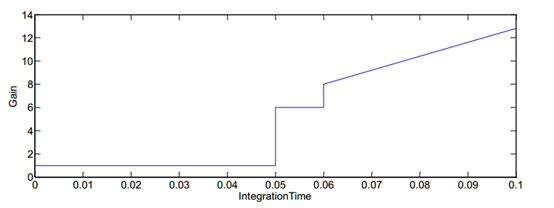
Figure 4-2 Schematic diagram of exposure decomposition
There is no limit to the number of nodes in the exposure decomposition curve, It is recommended to set at least 6 nodes to prevent the exposure decomposition transition from being unsmooth.
The exposure amount of a node is the product of each component, such as exposure time, sensor gain, ISP digital gain, and aperture equivalent gain. The exposure of the node must be monotonically incremented, that is, the exposure of the next node must be greater than the exposure of the previous node. The first node has the least exposure, and the second node has the most exposure.
The unit of the exposure time component in the node is seconds, and the minimum value is allowed to be 0, and the actual minimum exposure time code will be corrected according to the sensor limit.
The aperture component only supports P-Iris, not DC-Iris. The P-iris equivalent gain component is only valid when the Airis auto-iris function is enabled, otherwise the default aperture is fixed at the default value. The calculation of the P-iris equivalent gain is detailed in the AecIrisCtrl module.
The set Exposure Explode Route node is not the final exposure explode route. The actual maximum/minimum value of each exposure component in the final system is determined by both the exposure decomposition node and the manually configured maximum/minimum value of the exposure component. When the maximum/minimum value of the node does not exceed the limit of the sensor or ISP, the maximum/minimum value of the node remains unchanged, and when the maximum/minimum value of the node exceeds the limit of the sensor or ISP, the maximum/minimum value of the node shall prevail according to the limit of the sensor or ISP. When the maximum/minimum value of the manually configured exposure component is 0, the final effective exposure decomposition route shall be subject to the decomposition route of the first correction;When the maximum/minimum value of the manually configured exposure component is not 0, and the maximum/small value set does not exceed the limit of the sensor or ISP, the second correction of the exposure decomposition route shall be made, and the maximum/small value of the node shall be subject to the manually set range; if the maximum/small value of the exposure component is set/ When the small value exceeds the limit of the sensor or ISP, the maximum/small value of the node of the exposure component of the exposure decomposition route shall be subject to the first correction result. If the exposure of an adjacent node increases, only one exposure component should increase, and the other exposure components are fixed. The added components determine the allocation strategy for that segment of the route. For example, if the gain component increases and the other components are fixed, then the allocation strategy for this section of the route is gain priority.
The 3588 platform does not support ISP digital gain, so the IspgainDot parameter is invalid.
1.2.2.6 InitExp
【Description】
Linear exposure mode initial value setting.
【Members】
| Member name | Description |
|---|---|
| InitTimeValue | Initial exposure time value in seconds |
| InitGainValue | The initial sensor gain value, where the gain value is the actual value, in units of 1x |
| InitIspDGainValue | The initial ISP digital gain value, where the gain value is the actual value, in units of 1x |
| InitPIrisGainValue | The initial P-aperture is equivalent to the gain value, where the gain value is the actual value in units of 1x |
| InitDCIrisDutyValue | The initial DC aperture duty cycle value in the range of [0,100] |
【Precautions】
When the initial auto exposure value is not set (that is, when each value is 0), the system default value is used.
The size of the initial AE value, limited by the maximum/small value of the AE decomposition curve. When the size of the initial value of the auto exposure exceeds or falls below the maximum/small value of the auto exposure decomposition curve, it is replaced by the maximum/small value of the auto exposure decomposition curve.
Auto exposure P-aperture equivalent gain initial, valid only when the aperture type is P-aperture, the default initial value is the equivalent gain value corresponding to the maximum aperture supported by the P aperture. The meaning of equivalent gain is described in the Aperture Tuning Parameter IrisCtrl module.
Auto exposure DC aperture duty cycle initial value, valid only when the aperture type is DC aperture, the default initial value is the MaxPwmValue value of DC aperture, at which point DC-iris will open the aperture at maximum speed. The duty cycle and the meaning of MaxPwmValue are described in the Aperture Tuning Parameter IrisCtrl module.
The 3588 platform does not support ISP digital gain, so InitIspDGainValue is invalid.
1.2.2.7 DySetpoint
【Description】
Dynamic target brightness value setting.
【Members】
| Member name |
Description |
|---|---|
| ExpLevel | Dynamic exposure node attribute, the node value is the current exposure value, the number of nodes is not limited, it is recommended to set at least 6 nodes to prevent the exposure transition from being smooth. |
| DySetpoint | The higher the exposure node value, the smaller the target brightness node value, and corresponds to the exposure node one-to-one. There is no limit to the number of nodes, and it is recommended that you set at least 6 nodes to prevent the exposure transition from being smooth. |
【Precautions】
ExpLevel is the current exposure value, i.e. (Curgain * Curtime).
If you need to set a fixed target value, the value of each node in DySetpoint can be set to the same value.
When setting DySetpoint nodes, try to make the values of each node change smoothly with ExpLevel to prevent flickering.
1.2.2.8 BackLightCtrl
【Description】
The backlight compensation function, that is, in the backlight scene, supports the brightness of the dark area of the backlight to reproduce the details of the dark area.
【Members】
| Member name | Description |
|---|---|
| Enable | Module enable bit, 1: enabled, 0: off |
| MeasArea | Dark area detection area, including a total of 6 modes: AECV2_MEASURE_AREA_AUTO/UP/BOTTOM/LEFT/RIGHT/CENTER |
| LumaDistTh | Regional growth tolerance |
| OEROILowTh | The minimum brightness value of the overexposed area, which distinguishes the overexposed area from the non-overexposed area |
| LvHighTh | Ambient brightness high threshold |
| LvLowTh | Ambient brightness low threshold |
| ExpLevel | Dynamic exposure node attribute, the node value is the current exposure value, the number of nodes is not limited, it is recommended to set at least 6 nodes to prevent the exposure transition from being smooth. The node value is the exposure value (gain*time, time in s) |
| NonOEPdfHighTh | The proportion threshold of non-overexposed area (0~1), the number of nodes is not limited, it is recommended to set at least 6 nodes to prevent the exposure transition from being smooth. The number of nodes needs to be consistent with ExpLevel, and the node value needs to correspond to ExpLevel. |
| LowLightPdfTh | The dark area ratio threshold (0~1), the number of nodes is not limited, it is recommended to set at least 6 nodes to prevent the exposure transition from being smooth. The number of nodes needs to be consistent with ExpLevel, and the node value needs to correspond to ExpLevel. |
| TargetLLLuma | The number of nodes in the dynamic dark area is not limited, and it is recommended to set at least 6 nodes to prevent the exposure transition from being smooth. The number of nodes must be the same as that of the ExpLevel, and the node value must correspond to the ExpLevel one-to-one, which decreases as the ExpLevel increases |
【Precautions】
An important step in the backlight compensation function is to determine the location of the dark area (area of interest) of the backlight, and then increase the brightness of the dark area by increasing the exposure. The detection of backlight dark areas is divided into automatic mode and manual mode, which are configured in MeasArea, and include a total of 6 modes: AUTO, UP, BOTTOM, LEFT, RIGHT, CENTER. When MeasArea is configured as AUTO, it means that the backlight dark area is automatically detected. When MeasArea is configured as UP, BOTTOM, LEFT, RIGHT or CENTER, it represents manual mode, and the position of the dark area is subject to manual settings.
When MeasArea is configured as AUTO, dark areas are looked for based on the brightness distribution of the subwindow and the probability of backlighting in the current scene. The backlight probability of the current scene is mainly composed of three factors: ambient brightness factor (Lv_fac), dark area ratio factor (DarkPdf_fac), and contrast factor (Contrast_fac). The parameters associated with the three factors are described below.
ambient brightness Lv=meanluma/exp/1000 (exp=gain*time, unit:s)
LvHighTh: High ambient brightness threshold, the higher the value, the less likely it is to trigger backlight compensation, and vice versa, it is easier to trigger backlight compensation. Equivalent to distinguishing between indoor and outdoor ambient brightness thresholds, LvHighTh=setpoint/ is recommended. This parameter is valid when MeasArea is configured as AUTO.
LvLowTh: low ambient brightness threshold, the higher the value, the less likely it is to trigger backlight compensation, and vice versa. Equivalent to the ambient brightness threshold that distinguishes between indoor light and dark environments, LvHighTh=setpoint/ is recommended. This parameter is valid when MeasArea is configured as AUTO.
The above high and low thresholds for ambient brightness are used to calculate the ambient brightness factor. LowLightPdfTh Dark area proportion threshold, which affects the calculation of dark area proportion factor. The proportion of dark areas should not be too large, otherwise it is easy to trigger backlight compensation, resulting in excessive brightness in the indoor environment. It is recommended that the proportion of dark areas in bright environments be controlled within 20%, and the proportion of dark areas increases as the ambient brightness decreases. This parameter is valid when MeasArea is configured as AUTO.
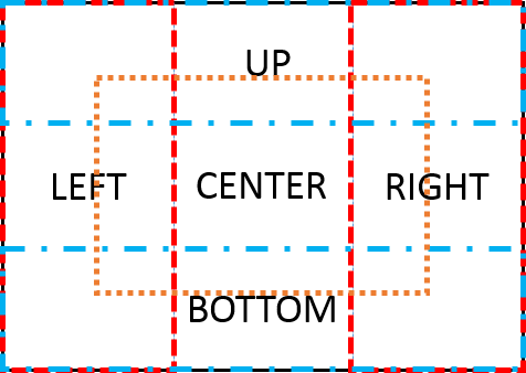
Figure 4-3 Backlit MeasArea area
When MeasArea is set to UP, BOTTOM, LEFT, RIGHT, or CENTER, the MeasArea is set to manual mode. When the brightness of the specified area is lower than the target brightness value of the dark area, increase the exposure to increase the brightness of the specified area, and when the brightness of the specified area is higher than the target brightness value of the dark area, it means that the specified area is not a dark area or the current scene is not a backlit scene, then the increase or decrease of exposure is determined by the global brightness. That is, in this mode, the backlight compensation is only enabled when the brightness of the specified area is lower than the target brightness value of the dark area.
TargetLLLuma dark area brightness target value. The target value of dark area brightness should not exceed 50% of the global brightness target value, and it is recommended to control it at 40%~50% of the global target brightness%, otherwise the brightness may be too bright in the backlight scene. MeasArea is configured with any value, and the parameter is valid.
1.2.2.9 OverExpCtrl
【Description】
Bright light suppression module to reduce exposure and reduce the degree of overexposure of the picture.
【Members】
| Member name | Description |
|---|---|
| Enable | Module enable bit, 1: enabled, 0: off |
| HighLightTh | Brightness threshold for highlighted areas, value range [0,255] |
| LowLightTh | Brightness threshold for low-light areas, value range [0,255] |
| MaxWeight | Maximum weight value |
| OEPdf | The proportion of overexposed area, the number of nodes is not limited, it is recommended to set at least 6 nodes to prevent the exposure transition from not smooth, the proportion value changes from small to large, the value range is [0,1] |
| HighLightWeight | The weight of the highlighted area, the number of nodes is not limited, it is recommended to set at least 6 nodes to prevent the exposure transition from being smooth, corresponding to the proportion of the overexposed area node, the maximum value is limited by MaxWeight. |
| LowLightWeight | Low highlight area weight, the number of nodes is not limited, it is recommended to set at least 6 nodes to prevent the exposure transition is not smooth, corresponding to the proportion of overexposed area nodes, the maximum value is limited by MaxWeight. |
【Precautions】
HighLightTh represents the brightness threshold of the highlighted area, and the areas above the brightness threshold are considered as the highlighted area, corresponding to the weight of HighLightWeight. LowLightTh represents the brightness threshold of the low-light area, and the area with a brightness below the threshold is considered a low-light area, and the corresponding weight is LowLightWeight. The brightness is located in the area between LowLightTh and HighLightTh, and its weight value is an interpolation of LowLightWeight and HighLightWeight.
The larger the HighLightWeight, the greater the intensity of the suppression of strong light, and vice versa. The larger the LowLightWeight, the less powerful the suppression of strong light, and vice versa. It is recommended that HighLightWeight be controlled in the range of 1~4, and LowLightWeight be controlled in the range of 0.7~1.
Bright light suppression module, if you suppress strong light in any scene with overexposed areas, many scenes will have the phenomenon that the overall picture is too dark. Therefore, HighLightWeight should not be too large, it is recommended that with the increase of the proportion of overexposed area, HighLightWeight is reduced, in order to avoid excessive suppression of strong light, resulting in the overall brightness of the picture is too dark.
When the strong light suppression module is turned on, it is recommended to enable the linear TMO function at the same time to prevent the problem of too dark dark areas during the strong light suppression process.
1.2.3 4.1.2.3 AEC module HDR exposure debugging parameters
| Parameter name | Parameter type | Brief description |
|---|---|---|
| ToleranceIn/Out | Debug parameters | User debugging parameters |
| StrategyMode | Debug parameters | User debugging parameters |
| EvBias | Debug parameters | User debugging parameters |
| ExpRatioCtrl | Debug parameters | User debugging parameters |
| Route | Debug parameters | User debugging parameters |
| InitExp | Debug parameters | User debugging parameters |
| LongFrmMode | Debug parameters | User debugging parameters |
| LframeCtrl | Debug parameters | User debugging parameters |
| MframeCtrl | Debug parameters | User debugging parameters |
| SframeCtrl | Debug parameters | User debugging parameters |
1.2.3.1 ToleranceIn/Out
【Description】
The tolerance of the brightness of the picture. The unit is % and the value range is [0,100]
When the AE converges, the screen brightness value B should be within the range of [True Effective Target Luminance X(1-tolerance/100), True Effective Target Luminance X(1+Tolerance/100)].
ToleranceIn represents tolerance when exposure does not converge, and ToleranceOut represents tolerance when exposure converges. ToleranceIn < ToleranceOut is recommended to avoid excessive sensitivity to exposure changes and stabilize exposure.
1.2.3.2 StrategyMode
【Description】
Auto exposure strategy mode, highlight priority or low light priority.
【Members】
Highlight priority: AECV2_STRATEGY_MODE_HIGHLIGHT_PRIOR
Low light priority: AECV2_STRATEGY_MODE_LOWLIGHT_PRIOR
【Precautions】
This parameter behaves differently in different exposure ratio modes, see ExpRatioCtrl parameter.
1.2.3.3 EvBias
【Description】
When adjusting the automatic exposure, the percentage deviation of the exposure amount in % is in the range of [-200, +200]. It is used to adjust the target brightness value in special scenarios. The true effective target brightness is the target value X [1+abs(EvBias)/100]^[EvBias/abs(EvBias)].
If EvBias=100 is set, the target brightness is twice the default parameter. When EvBias=-100, the target brightness is 1/2 of the default parameter.
【Precautions】
For example, the toleranceIn/Out setting above is large, which will affect the response speed of AE on the one hand, and the EvBias value on the other hand. When the interval value of EvBias adjustment is lower than toleranceIn/Out, it may cause the brightness adjustment to not take effect.
1.2.3.4 InitExp
【Description】
HDR exposure mode initial value setting.
【Members】
| Member name | Description |
|---|---|
| InitTimeValue | Initial exposure time value in seconds |
| InitGainValue | The initial sensor gain value, where the gain value is the actual value, in units of 1x |
| InitIspDGainValue | The initial ISP digital gain value, where the gain value is the actual value, in units of 1x |
| InitPIrisGainValue | The initial P-aperture is equivalent to the gain value, where the gain value is the actual value in units of 1x |
| InitDCIrisDutyValue | The initial DC aperture duty cycle value in the range of [0,100] |
【Precautions】
When the initial auto exposure value is not set (that is, when each value is 0), the system default value is used.
The size of the initial AE value, limited by the maximum/small value of the AE decomposition curve. When the size of the initial value of the auto exposure exceeds or falls below the maximum/small value of the auto exposure decomposition curve, it is replaced by the maximum/small value of the auto exposure decomposition curve.
Some sensors have special requirements for initial exposure in HDR exposure mode, such as os04a10, which requires the initial exposure of short frames to be less than 0.005s.
Auto exposure P-aperture equivalent gain initial, valid only when the aperture type is P-aperture, the default initial value is the equivalent gain value corresponding to the maximum aperture supported by the P aperture. The meaning of equivalent gain is described in the AecIrisCtrl module.
Auto exposure DC aperture duty cycle initial value, valid only when the aperture type is DC aperture, the default initial value is the MaxPwmValue value of DC aperture, at which point DC-iris will open the aperture at maximum speed. The duty cycle and the meaning of MaxPwmValue are described in the AecIrisCtrl module.
The 3588 platform does not support ISP digital gain, so InitIspDGainValue is invalid.
1.2.3.5 Route
【Description】
Auto Exposure Decomposition strategy properties. Used to set the AE exposure decomposition route, the exposure calculated by the AE algorithm will be distributed according to the set route, and the user can set the route to exposure time priority (shutter priority), gain priority, and aperture priority according to the needs of the specific application.
【Members】
| Member name | Description |
|---|---|
| Frm0/1/2TimeDot | Exposure time node, in seconds. In HDR 2 frame mode, only Frm0/1TimeDot is valid; In HDR 3 frame mode, Frm0/1/2TimeDot is valid. FRM0~3 is the frame sequence number from short to long exposure |
| Frm0/1/2GainDot | sensor gain node. Only Frm0/1GainDot works in Hdr 2 frame mode, and Frm0/1/2GainDot works in Hdr 3 frame mode. The gain value here is the actual value and is in units of 1x. FRM0~3 is the sequence number of frames with exposure from short to long. |
| Frm0/1/2IspDGainDot | ISP Digital Gain Nodes. In Hdr 2 frame mode, only Frm0/1IspDGainDot is valid, and in Hdr 3 frame mode, Frm0/1/2IspDGainDot is in effect. The gain value here is the actual value and is in units of 1x. FRM0~3 is the sequence number of frames with exposure from short to long |
| PIrisDot | The aperture is equivalent to the gain node, where the gain value is the actual value in units of 1x |
【Precautions】
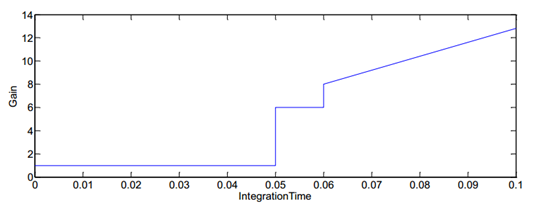
Figure 4-2 Schematic diagram of exposure decomposition
There is no limit to the number of nodes in the exposure decomposition curve, It is recommended to set at least 6 nodes to achieve smooth exposure decomposition.
In HDR 2 frame mode, you only need to set Frm0/1TimeDot, Frm0/1GainDot, and Frm0/1IspDGainDot to correspond to the actual short and long frames, respectively, and in HDR 3 frame mode, you need to set Frm0/1/2TimeDot, Frm0/1/2GainDot, and Frm0/1/2IspDGainDot to correspond to short, medium, and long frames, respectively. When setting the sensor exposure time of each frame in HDR mode, you need to allocate the exposure time reasonably, and the sum of the exposure time of each frame cannot exceed the maximum exposure time allowed by the frame rate!
The exposure amount of a node is the product of each component, such as exposure time, sensor gain, ISP digital gain, and aperture equivalent gain. The exposure of the node must be monotonically incremented, that is, the exposure of the next node must be greater than the exposure of the previous node. The first node has the least exposure, and the second node has the most exposure.
The unit of the exposure time component in the node is seconds, and the minimum value is allowed to be 0, and the actual minimum exposure time code will be corrected according to the sensor limit.
The aperture component only supports P-Iris, not DC-Iris. The P-iris equivalent gain component is only valid when the Airis auto-iris function is enabled, otherwise the default aperture is fixed at the default value. The calculation of the P-iris equivalent gain is detailed in the AecIrisCtrl module.
The set Exposure Explode Route node is not the final exposure explode route. The actual maximum/minimum value of each exposure component in the final system is determined by both the exposure decomposition node and the manually configured maximum/minimum value of the exposure component. When the maximum/minimum value of the node does not exceed the limit of the sensor or ISP, the maximum/minimum value of the node remains unchanged, and when the maximum/minimum value of the node exceeds the limit of the sensor or ISP, the maximum/minimum value of the node shall prevail according to the limit of the sensor or ISP. When the maximum/minimum value of the manually configured exposure component is 0, the final effective exposure decomposition route shall be subject to the decomposition route of the first correction;When the maximum/minimum value of the manually configured exposure component is not 0, and the maximum/small value set does not exceed the limit of the sensor or ISP, the second correction of the exposure decomposition route shall be made, and the maximum/small value of the node shall be subject to the manually set range; if the maximum/small value of the exposure component is set/ When the small value exceeds the limit of the sensor or ISP, the maximum/small value of the node of the exposure component of the exposure decomposition route shall be subject to the first correction result.
If the exposure of an adjacent node increases, only one exposure component should increase, and the other exposure components are fixed. The added components determine the allocation strategy for that segment of the route. For example, if the gain component increases and the other components are fixed, then the allocation strategy for this section of the route is gain priority.
3588 does not currently support ISP digital gain, so Frm0/1/2ispDGainDot are invalid.
1.2.3.6 ExpRatioCtrl
【Description】
HdrAE exposure ratio control module.
【Members】
| Member name |
Description |
|---|---|
| ExpRatioType | Exposure ratio mode, valid only under HDR mode multi-frame compositing AUTO: Automatically calculates the exposure ratio of long and short frames according to the scene FIX: Fixed exposure ratio for long and short frames |
| RatioExpDot | Indicates the exposure node, according to the exposure amount, dynamically set the exposure ratio fixed value or the maximum exposure ratio, the two correspond one-to- one. The number of nodes is not limited, It is recommended to set at least 6 nodes to achieve smooth exposure transition. |
| M2SRatioFix | The number of nodes is not limited, It is recommended to set at least 6 nodes to achieve smooth exposure transition. The number of nodes must be the same as the number of RatioExpDot nodes. ExpRatioType = AUTO, not valid. When ExpRatioType = FIX, it indicates the exposure ratio of medium frame to short frame, which corresponds to the exposure node RatioExpDot. |
| L2MRatioFix | The number of nodes is not limited, It is recommended to set at least 6 nodes to achieve smooth exposure transition. The number of nodes must be the same as the number of RatioExpDot nodes. ExpRatioType = AUTO, not valid. When ExpRatioType = FIX, it represents the exposure ratio of long frames to medium frames, which corresponds to the exposure node RatioExpDot. HDR is not valid when compositing at 2 frames, and valid when compositing at 3 frames |
| M2SRatioMax | The number of nodes is not limited, It is recommended to set at least 6 nodes to achieve smooth exposure transition. The number of nodes must be the same as the number of RatioExpDot nodes. When ExpRatioType = AUTO, it indicates the dynamic maximum exposure ratio of medium and short frames, which corresponds to the exposure node RatioExpDot. ExpRatioType = FIX, invalid |
| L2MRatioMax | The number of nodes is not limited, It is recommended to set at least 6 nodes to achieve smooth exposure transition. The number of nodes must be the same as the number of RatioExpDot nodes. When ExpRatioType = AUTO, it indicates the dynamic maximum value of the exposure ratio between long and medium frames, which corresponds to the exposure node RatioExpDot. HDR is not valid for 2-frame synthesis and valid for 3-frame compositing. ExpRatioType = FIX, not valid. |
【Precautions】
ExpRatioType is AUTO, using auto exposure ratio mode. In 2-frame mode, the maximum exposure ratio of long and short frames is limited by M2SratioMax; In 3-frame mode, the maximum exposure ratio of short and medium frames is limited by M2SratioMax, and the maximum exposure ratio of long and medium frames is limited by L2MratioMax. The minimum exposure ratio is unlimited, and must not be less than 1. ExpRatioType is FIX, which uses a fixed exposure mode. In 2-frame mode, the exposure ratio of long and short frames is M2SRatioFix; In 3-frame mode, the exposure ratio is M2SRatioFix for short and medium frames, and L2MratioFix for long medium frames.
Auto exposure ratio mode, 2-frame HDR mode, when the exposure ratio of long and short frames obtained by the AEC control algorithm module exceeds the maximum exposure ratio M2SratioMax limit, select the frame that needs to be prioritized to ensure exposure according to StrategyMode. StrategyMode = HIGHLIGHT_PRIOR, priority is given to ensuring the exposure of short exposure frames, long exposure frame exposure = short exposure frame exposure * M2SratioMax; StrategyMode = LOWLIGHT_PRIOR, priority is given to ensuring exposure of long exposure frames, short exposure frame exposure = long exposure frame exposure/M2SratioMax. By analogy, in 3-frame HDR mode, when StrategyMode = HIGHLIGHT_PRIOR, priority is given to ensuring exposure of shorter frames; StrategyMode = LOWLIGHT _PRIOR, which prioritizes exposure for longer frames. Fixed exposure ratio mode, 2 frames HDR mode, StrategyMode = HIGHLIGHT_PRIOR, based on the exposure of short exposure frames, calculate long exposure frame exposure, equal to short exposure frame exposure * M2SRatioFix; StrategyMode = LOWLIGHT_PRIOR, based on the exposure of the long exposure frame, calculate the short exposure frame exposure, equal to the long exposure frame exposure / M2SRatioFix. 3 fps HDR mode, and so on.
1.2.3.7 LongFrmMode
【Description】
HdrAE long frame mode function control module
【Members】
| Member name | Description |
|---|---|
| Mode | Long frame mode, including: NORMAL/AUTO_LONGFRAME/LONGFRAME NORMAL: Normal Hdr mode. The AE and HDR synthesis modules work according to the manual/automatic exposure ratio. AUTO_LONGFRAME: Auto long frame mode. When the exposure exceeds the set threshold, the long frame exposure time is close to the maximum allowed for 1 frame, and the compositing module only outputs long frames. LONGFRAME: LONG FRAME MODE. AE sets the short frame exposure time to the minimum, the long frame exposure time is close to the maximum value allowed for 1 frame, and the compositing module only outputs long frames |
| SfrmMinLine | Long frame mode/auto long frame mode, short frame minimum exposure line. Due to some limitations of the sensor, the minimum exposure line for short frames in long frame mode may not reach the minimum exposure line allowed by the sensor, so it needs to be set separately |
| LfrmModeExpTh | In Auto Long Frame mode, when the exposure of long frames exceeds LfrmModeExpTh, switch to Long Frame Mode |
1.2.3.8 LframeCtrl
【Description】
Long frame debugging parameters. In the HdrAE strategy, in the 2-frame mode, long frames need to be compatible with general dynamic range scenes and backlit scenes, so there are two brightness constraints: global target brightness and dark area target brightness. While ensuring that the global brightness of long frames is within the tolerance range of the global target brightness, the dark area brightness is required to be greater than or equal to the dark area target brightness.
【Members】
| Member Name | Description |
|---|---|
| OEROILowTh | The lowest brightness value for the overexposed area, which is used to distinguish the overexposed area from the non-overexposed area |
| LvHighTh | Ambient brightness high threshold |
| LvLowTh | Ambient Brightness Low Threshold |
| LExpLevel | The number of nodes is not limited, It is recommended to set at least 6 nodes to achieve smooth exposure transition. ExpLevel =gain*time(time in s) |
| LSetPoint | The number of nodes must be consistent with the number of nodes in the LExpLevel, and the node values must correspond to the values of each node in the LExpLevel |
| NonOEPdfHighTh | The threshold of the proportion of non-overexposed areas (0~1), the number of nodes must be consistent with LExpLevel, and the node value must correspond to LExpLevel one-to-one |
| LowLightPdfTh | The number of nodes must be consistent with the number of nodes in LExpLevel, and the node value must correspond to the value of each node in LExpLevel, and increase with the increase of ExpLevel |
| TargetLLLuma | The number of nodes in the dynamic long-frame dark area must be consistent with the LExpLevel, and the node value must correspond to the value of each node in the LExpLevel one-to-one, and decrease as the ExpLevel increases |
【Precautions】
ambient brightness Lv=meanluma/exp/1000 (exp=gain*time,unit:s)
LvHighTh: High ambient brightness threshold, the higher the value, the less likely it is to trigger backlight compensation, and vice versa, it is easier to trigger backlight compensation. Equivalent to distinguishing between indoor and outdoor ambient brightness thresholds, LvHighTh=setpoint/ is recommended.
LvLowTh: low ambient brightness threshold, the higher the value, the less likely it is to trigger backlight compensation, and vice versa. Equivalent to the ambient brightness threshold that distinguishes between indoor light and dark environments, LvHighTh=setpoint/ is recommended.
The above high and low thresholds for ambient brightness are used to calculate the ambient brightness factor.
LowLightPdfTh Dark area proportion threshold, which affects the calculation of dark area proportion factor. The proportion of dark areas should not be too large, otherwise it is easy to trigger backlight compensation, resulting in excessive brightness in the indoor environment. It is recommended that the proportion of dark areas in bright environments be controlled within 20%, and the proportion of dark areas increases as the ambient brightness decreases.
It is recommended that the target value of the dark area should not exceed 50% of the global target value, and control it at 40%~50% of the global target brightness, otherwise the brightness may be too bright in the backlight scene.
1.2.3.9 MframeCtrl
【Description】
Medium frame debugging parameters (valid only at HDR 3 frames)
【Members】
| Member name |
Description |
|---|---|
| MExpLevel | Dynamic frame exposure value node parameter, the number of nodes is not limited, It is recommended to set at least 6 nodes to achieve smooth exposure transition. ExpLevel = gain*time(time units are s) |
| MSetPoint | The number of nodes must be consistent with the MExpLevel value of the global target brightness value of the dynamic medium frame, and the node value must correspond to the value of each node in MExpLevel. As the exposure grows, the target decreases. |
1.2.3.10 SframeCtrl
【Description】
Short frame debugging parameters
【Members】
| Member name | Description |
|---|---|
| SExpLevel | Dynamic short frame maximum exposure value node parameter, the number of nodes is not limited, It is recommended to set at least 6 nodes to achieve smooth exposure transition. ExpLevel = gain*time(time units are s) |
| SSetPoint | The number of nodes must be consistent with the target global average brightness of dynamic short frames, and the node values must correspond to the values of each node in MExpLevel. The target brightness value of the bright area in the same interval must be higher than the corresponding global brightness target value. |
| TargetHLLuma | The average target value of the dynamic short frame highlight area, the number of nodes must be consistent with MExpLevel, and the node value should correspond to the value of each node in MExpLevel. |
| HLLumaTolerance | Sets the target tolerance percentage for short frame highlights in % |
| HLROIExpandEn | Short frame highlight area extension enabled. =1, ignore the small highlight area, reduce the sensitivity of the highlight area; =0 to suppress the brightness of all highlighted areas and increase the sensitivity of the highlighted areas |
1.2.4 4.1.2.4 AEC module aperture debugging parameters
IrisCtrl
【Description】
Aperture control parameters
【Members】
| Member name | Description |
|---|---|
| Enable | Automatic iris control function enabled |
| IrisType | Aperture type, P (i.e. P-iris aperture) or DC (i.e. DC-iris aperture) |
| ManualEn | Manual Aperture Enable |
| InitAttr | Aperture Initial Value Parameter |
| DCIrisAttr | DC Aperture Control Parameters |
ManualAttr
| Member name | Description |
|---|---|
| PIrisGainValue | Manual P-aperture equivalent gain value, where the gain value is the actual value, the unit is 1x, and the parameter value is limited by the P aperture device, the value range is [1,1024] |
| DCIrisHoldValue | Manual DC aperture HoldValue value, parameter value is related to DC aperture device, the value range is [0,100] |
InitAttr
| Member name | Description |
|---|---|
| PIrisGainValue | P-aperture equivalent to the initial gain value, where the gain value is the actual value, the unit is 1x, and the parameter value is limited by the P aperture device, the value range is [1,1024] |
| DCIrisHoldValue | DC aperture HoldValue value, parameter value is related to DC aperture device, the value range is [0,100] |
PIrisAttr
| Member name |
Description |
|---|---|
| TotalStep | The total number of steps of the P-iris stepper motor, the specific size is related to the P-iris lens. |
| EffcStep | The number of steps available for the P-iris stepper motor, the specific size is related to the P-iris lens |
| ZeroIsMax | Whether the P-iris stepper motor step0 corresponds to the maximum aperture position, the specific value is related to the P-iris lens. This value is 0, which means that when the stepper motor position is step0, the aperture is turned to the minimum; The value is 1, which means that when the stepper motor position is step0, the aperture is turned to the maximum. |
| StepTable | A mapping table of the position of the P-iris stepper motor to the equivalent gain of the aperture, the specific value is related to the P-iris lens |
DCIrisAttr
| Member name | Description |
|---|---|
| Kp | A scale factor that limits the switching speed of the aperture drastically changing timecircle, the larger the value, the slower the light aperture changes the timecircle opens and closes. If this value is too large, the adjustment process braking will be ahead, resulting in too long adjustment time; If this value is too small, the braking will lag behind during the adjustment process, resulting in an increase in overshoot. The reasonable setting of this value is related to the DC-iris lens and circuit characteristics. The recommended value is 0.5. The range of values is [0,1]. |
| Ki | The integration coefficient that adjusts the switching speed of the aperture, the larger the aperture, the greater the speed at which the aperture opens and closes. This value is too large, and it is easy to overshoot and cause oscillation; If this value is too small, oscillations tend to occur when the aperture adjustment speed is slower and the ambient brightness changes sharply. The recommended value is 0.2. The range of values is [0,1]. |
| Kd | A differential coefficient that adjusts the switching speed of the aperture, the larger the value, the greater the speed at which the aperture opens and closes. The recommended value is 0.3. The range of values is [0,1]. |
| MinPwmDuty | Minimum PWM duty cycle, the specific size is related to the DC-iris lens and circuit characteristics, in %. The smaller the value, the faster the supported aperture closes, but tends to cause aperture oscillation. The value range is [0,100], and the default value is 0. |
| MaxPwmDuty | The maximum PWM duty cycle, the specific size is related to the DC-iris lens and circuit characteristics, in %. A higher value opens the supported aperture faster, and too small a value may cause the aperture control to exit before the maximum aperture has been reached. The value range is [0,100], and the default value is 100. |
| OpenPwmDuty | PWM duty cycle threshold when aperture open, aperture on when aperture PWM duty cycle is higher than (not included) OpenPwmDuty. The specific size is related to the DC-iris lens in % value range [0,100]. |
| ClosePwmDuty | PWM duty cycle threshold when aperture is off, aperture off when aperture PWM duty cycle is less than (not included) ClosePwmDuty. The specific size is related to the DC- iris lens in % value range [0,100]. |
【Precautions】
When the auto iris function is turned off, for DC-iris aperture, it will be turned on to the maximum by default; For the P-iris aperture, the stepper motor position corresponding to the maximum aperture is turned on by default. If you want to change the above aperture position, you can modify PIrisGainValue and DCIrisHoldValue in the InitAttr module.
ManualIrisEn, manual iris control enabled. When the aperture type IrisType is P-aperture, only PirisGainValue is valid; When the aperture type is DC aperture, only DCIrisHoldValue is valid.
DCIrisHoldValue, directly set the PWM duty cycle value of the motor in manual mode, the value range [0,100]. If the HoldValue value is set in manual mode (that is, the value in the ClosePwmDuty to OpenPwmDuty range in DCIrisAttr), the DC aperture aperture remains at the current size; If the value set is greater than OpenPwmDuty, the aperture is turned on, and the larger the value, the greater the opening speed; If the value set is less than ClosePwmDuty, the aperture is off, and the smaller the value, the greater the speed of closing.
The basic control flow of the automatic iris Airis algorithm is as follows:
For DC-iris lenses, Airis controls the aperture size of the DC-iris lens based on the deviation of the current brightness from the target brightness. When the exposure reaches the minimum value, and the current brightness exceeds the target brightness tolerance range, the AE control will be exited, and the exposure time and exposure gain will be fixed and enter the AIRIS control range. If the current screen brightness is stable and the PWM duty of DC-iris is greater than OpenPwmDuty, the current aperture is considered to have reached the maximum, and the Airis aperture control is withdrawn, and the control is handed over to AE.
For P-iris lenses, aperture control is performed via the AecRoute module. The aperture size of the P-iris lens is converted to the equivalent gain and participates in the exposure decomposition calculation.
P-iris stepper motor position and aperture equivalent gain mapping table StepTable is generally made according to the correspondence between stepper motor position and aperture aperture provided by lens manufacturers. The control of P-iris is controlled by AE’s AecRoute module, which converts the aperture aperture size into equivalent gain, so P-iris control needs to have good linearity. The equivalent gain ranges from [1,1024], with an equivalent gain of 1024 for F1.0, an equivalent gain of 512 for F1.4, and so on, an equivalent gain of 1 for F32.0. When making a table, it is necessary to convert the aperture aperture corresponding to the stepper motor position to the equivalent gain, fill it in the StepTable, and fix it to increment according to the stepper motor position (i.e. step0, step1…). stepN).
TotalStep represents the total number of steps of the P-iris stepper motor, and the specific size is related to the P-iris lens. EffcStep indicates the number of steps available for P-iris stepper motors, which is generally less than TotalStep. Because the position near the closed end of the aperture has a large error in the value corresponding to the equivalent gain, and oscillations are prone to occur during iris adjustment, the step position near the closed end of the aperture is usually not used.
Table 4-1 is a table corresponding to the position of the P-iris stepper motor to the aperture aperture and equivalent gain, and use this table as an example to illustrate how to set the StepTable. The correspondence between the stepper motor position step and the aperture aperture area in columns 1-2 and 4-5 in Table 4-1 is provided by a lens manufacturer. The P-iris lens has a stepper motor adjustment total of 81 steps, with the largest aperture aperture at step0 and a nominal maximum aperture of 1.4. A number of apertures of 1.4 corresponds to an equivalent gain of 512, so the equivalent gain at step 0 is 512. The equivalent gain corresponding to the other aperture areas, here taking step 3 as an example, is calculated as follows: the aperture area of step 3 is 195.869, and the corresponding equivalent gain = 512* (195.869/201.062)=499(rounded). By analogy, the equivalent gain values corresponding to the positions of other stepper motors can also be calculated from this. It can be seen from Table 1-1 that when the stepper motor position is close to the closed end, the corresponding aperture area is very small, and the difference from the largest aperture area can be thousands of times, and the corresponding equivalent gain value error is large, so it is recommended that the stepper motor position close to the closed end of the aperture should not be used, so as not to cause exposure oscillation due to errors. The equivalent gain corresponding to each stepper motor position in the table is incremented according to the stepper motor position (i.e., step0, step1…). stepN) is filled in the StepTable.
DC-iris’ OpenPwmDuty and ClosePwmDuty values need to be measured and are related to DC-iris lenses. For some lenses, when the PWM duty cycle is greater than OpenPwmDuty, the aperture performs an open operation; When the PWM duty cycle is less than OpenPwmDuty, the aperture performs a closed operation; When the PWM duty cycle is greater than or equal to ClosePwmDuty and less than or equal to OpenPwmDuty, the aperture is stable at the current position, and the values in this interval are HoldValue. In addition, there are some lenses, and there is only a threshold of the aperture switch, that is, when the PWM duty cycle is greater than this threshold, the aperture performs an open operation; When the PWM duty cycle is less than this threshold, the aperture performs a off operation; When the PWM duty cycle is equal to this threshold, the aperture stabilizes at the current position, which is HoldValue. In this case, you can make ClosePwmDuty = OpenPwmDuty = HoldValue.
Table 4-1 P-iris stepper motor position and aperture aperture and equivalent gain correspondence table
| Step | Aperture area(mm2) |
Equivalent gain |
Step | Aperture area(mm2) |
Equivalent gain |
|---|---|---|---|---|---|
| 0 | 201.062 | 512 | 41 | 56.653 | 144 |
| 1 | 200.759 | 511 | 42 | 53.438 | 136 |
| 2 | 198.583 | 506 | 43 | 50.282 | 128 |
| 3 | 195.869 | 499 | 44 | 47.188 | 120 |
| 4 | 192.879 | 491 | 45 | 44.159 | 112 |
| 5 | 189.677 | 483 | 46 | 41.197 | 105 |
| 6 | 186.293 | 474 | 47 | 38.307 | 98 |
| 7 | 182.744 | 465 | 48 | 35.49 | 90 |
| 8 | 179.035 | 456 | 49 | 32.751 | 83 |
| 9 | 175.271 | 446 | 50 | 30.093 | 77 |
| 10 | 171.484 | 437 | 51 | 27.519 | 70 |
| 11 | 167.681 | 427 | 52 | 25.034 | 64 |
| 12 | 163.865 | 417 | 53 | 22.642 | 58 |
| 13 | 160.036 | 408 | 54 | 20.347 | 52 |
| 14 | 156.198 | 398 | 55 | 18.154 | 46 |
| 15 | 152.351 | 388 | 56 | 16.068 | 41 |
| 16 | 148.499 | 378 | 57 | 14.096 | 36 |
| 17 | 144.642 | 368 | 58 | 12.245 | 31 |
| 18 | 140.783 | 359 | 59 | 10.522 | 27 |
| 19 | 136.925 | 349 | 60 | 8.935 | 23 |
| 20 | 133.069 | 339 | 61 | 7.484 | 19 |
| 21 | 129.217 | 329 | 62 | 6.169 | 16 |
| 22 | 125.371 | 319 | 63 | 4.987 | 13 |
| 23 | 121.535 | 309 | 64 | 3.936 | 10 |
| 24 | 117.709 | 300 | 65 | 3.014 | 8 |
| 25 | 113.897 | 290 | 66 | 2.22 | 6 |
| 26 | 110.1 | 280 | 67 | 1.55 | 4 |
| 27 | 106.321 | 271 | 68 | 1.003 | 3 |
| 28 | 102.562 | 261 | 69 | 0.577 | 1 |
| Step | Aperture area(mm2) |
Equivalent gain |
Step | Aperture area(mm2) |
Equivalent gain |
|---|---|---|---|---|---|
| 29 | 98.826 | 252 | 70 | 0.268 | 1 |
| 30 | 95.115 | 242 | 71 | 0.075 | 0 |
| 31 | 91.431 | 233 | 72 | close | 0 |
| 32 | 87.777 | 224 | 73 | close | 0 |
| 33 | 84.156 | 214 | 74 | close | 0 |
| 34 | 80.569 | 205 | 75 | close | 0 |
| 35 | 77.02 | 196 | 76 | close | 0 |
| 36 | 73.51 | 187 | 77 | close | 0 |
| 37 | 70.043 | 178 | 78 | close | 0 |
| 38 | 66.621 | 170 | 79 | close | 0 |
| 39 | 63.247 | 161 | 80 | close | 0 |
| 40 | 59.923 | 153 |
1.2.5 4.1.2.5 AEC module synchronously test parameters
SyncTest
【Description】
The synchronous test function of exposure and statistics supports cyclic setting of N groups of different exposure values according to the number of frames at a given interval. By cyclically setting the different exposure values of N groups, you can test whether the exposure time and exposure gain of the sensor, and the effective frame number of DCG switching are correct, and can also be used to test the linearity of the exposure, so as to confirm whether the register value conversion formula and related parameters of the exposure time and exposure gain are correct.
【Members】
| Member name | Description |
|---|---|
| Enable | Enables the simultaneous testing of exposure and statistics |
| IntervalFrm | Number of frames between exposure switching |
| AlterExp | Exposure switching parameters |
AlterExp
According to the different modes, it is divided into two sets of parameters: LinearAE and HdrAE.
| Member name | Description |
|---|---|
| TimeValue | Exposure time value |
| GainValue | Exposure gain value |
| IspDgainValue | ISP digital gain value |
| DcgMode | DCG mode value |
| PIrisGainValue | P-iris equivalent gain |
1.2.6 4.1.2.5 sensorinfo parameter
| Parameter name |
Parameter type | Brief description |
|---|---|---|
| Gain2Reg | CIS drive parameters |
CIS datasheet prevails, non-debugging parameters |
| Time2Reg | CIS drive parameters |
Based on CIS datasheet, the non-debug parameter is generally the default value, and there is no need to modify |
| CISGainSet | CIS drive parameters |
CIS datasheet prevails, non-debugging parameters |
| CISTimeSet | CIS drive parameters |
CIS datasheet prevails, non-debugging parameters |
| CISHdrSet | CIS drive parameters |
CIS datasheet prevails, non-debugging parameters |
| CISDcgSet | CIS drive parameters |
CIS datasheet prevails, non-debugging parameters |
| CISExpUpdate | CIS drive parameters |
CIS datasheet prevails, non-debugging parameters |
| CISMinFps | CIS drive parameters |
Generally, this is the default value, if you need to set a lower frame rate, you can modify |
| CISFlip | Debug parameters |
User debugging parameters Flip and mirror according to product application settings |
The sensorinfo parameter module, which is filled in by the driver or tuning personnel, is used to inform the CIS parameter information related to the exposure, which is convenient for debugging. Before tuning, you need to confirm whether the parameters of the module are consistent with the sensor datasheet, otherwise it may cause problems such as exposure flicker and HDR effect errors.
1.2.6.1 Gain2Reg
【Description】
The conversion formula configuration of the sensor gain value to register value. Due to the different gain conversion formulas of different sensor manufacturers, it can be roughly divided into linear (including piecewise linear, inverse proportional) and nonlinear. Nonlinearity is mainly for sensor manufacturers such as Sony, and currently only supports the gain conversion formula in dB mode.
【Members】
| Member name |
Description |
|---|---|
| GainMode | Gain conversion formula mode, EXPGAIN_MODE_NONLINEAR_DB nonlinear mode, EXPGAIN_MODE_LINEAR linear mode |
| GainRange | Linear gain conversion formula with piecewise linearity support. Valid when GainMode = EXPGAIN_MODE_LINEAR. |
【Precautions】
The sensor gain in the sensor gain register value formula means that the sensor’s total gain = again*dgain. If the conversion formula of again and dgain is different, the segmentation setting is supported, as shown in the figure above, and the size needs to be adaptively modified.
Linear sensor gain-to-register value formula, consisting of 3 coefficients (M0, C0, C1), the coefficients are described as follows:
The conversion formula is: set to driver reg = (gain^M0)*C1 - C0+ 0.5
XML parameters correspond to:
First column: gain interval start value, second column gain interval end value, third column: C1, fourth column: C0,
The fifth column: M0, the sixth column: gain start value corresponds to reg, and seventh column: gain end value corresponds to reg
When GainMode = EXPGAIN_MODE_NONLINEAR_DB, using the nonlinear sensor gain conversion formula, only dB mode is currently supported. The conversion formula corresponding to the dB mode is: reg = 20xlog10(gain)x10/3, this formula does not need to be filled in, and the algorithm uses this formula by default.
For DCG-enabled sensors and the conversion formula is linear, GainRange fills in the LCG’s gain conversion formula.
【Example】
s5kgm1sp
The analog gain and digital gain conversion formulas of this sensor are different, as shown in Fig. 4-3 and 4-4, the analog gain register value is 32 times the analog gain, and the digital gain register value is 256 times the digital gain.

Analog gain can be calculated as gain = x / 0x20. In S5KGM1ST03, analog gain is global; there is no per-channel gain. gain = x / 32; gain is supported up to X16.
Figure 4-3 Example of analog gain-to-register value
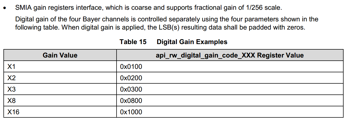
The SMIA gain register interface is coarse and supports fractional gain in units of 1/256. Digital gain of the four Bayer channels is controlled separately by the four parameters. When applying digital gain, pad the resulting LSB(s) with zeros. Table 15: digital gain examples.
| Gain value | api_rw_digital_gain_code_XXX register value |
|---|---|
| X1 | 0x0100 |
| X2 | 0x0200 |
| X3 | 0x0300 |
| X8 | 0x0800 |
| X16 | 0x1000 |
Figure 4-4 Example of digital gain-to-register value
The maximum analog gain of s5kgm1sp is known to be 16X, the maximum digital gain is 16X, and total gain = again*dgain. When Total gain <=16X, again is valid, dgain=1X; When Total gain > 16X, again = 16X, dgain is valid. Therefore, when filling in the conversion formula, [1,16] times total gain and [16,256] times total gain need to be configured separately, and the specific configuration is as follows:
[1.0000 16.0000 32.0000 0.0000 1.0000 32.0000 512.0000 16.0000 256.0000 16.0000 -512.0000 1.0000 768.0000 4608.0000 ]
[16,256] times Total gain interval, analog gain fixed at 16X (a_reg=16x32=512), digital gain d_reg = dgain x 256, and the corresponding configuration formula yields a register value reg=a_reg+d_reg = 512 + Total gain /16 x 256 = 512 + Total gain x 16, i.e. M0=1, C0=-512, C1=16. The total gain register value (hereinafter denoted by reg) issued by the application needs to be modified as follows:
  if(reg <= 0x200){
      a_reg = reg;
      d_reg = 0x0100;
  }else{
      a_reg = 0x200;
      d_reg = reg-0x200;
  }
1.2.6.2 Time2Reg
【Description】
The conversion formula for the number of exposure rows in the sensor exposure time transfer register consists of four coefficients (C0, C1, C2, C3).
Conversion formula: line = C0*VTS + C1 + C2 * (time * pclk / HTS + C3) XML corresponding parameters: First: C0, second: C1, third C2, fourth C3 According to the formula, the exposure time is calculated in reverse:
Time = ((line - C0 x vts - C1) / C2 - C3)*hts/pclk
【Precautions】
The default 4 coefficients are 0, 0, 1, 0.5, and the number of exposure lines obtained is incremented in 1 line. Generally, this value does not need to be modified.
1.2.6.3 CISGainSet
【Description】
CIS-related gain settings
【Members】
| Member name | Description |
|---|---|
| CISAgainRange | The range supported by sensor analog gain/LCG is minimum and maximum, respectively, where the minimum value must not be less than 1. - When the sensor supports dual conversion gain, this item indicates the LCG range supported by the sensor. - If a digital gain is encountered to complement the accuracy, this can represent the total gain range of the sensor |
| CISExtraAgainRange | The sensor analog gain (HCG) range, respectively, is the minimum and maximum value, where the minimum value must not be less than 1. - When the sensor supports dual conversion gain, this item indicates the HCG range supported by the sensor. - Range generally = CISAgainRange * dcg_ratio, but there are exceptions, such as ov2718. The specific datasheet given by the sensor factory shall prevail. - When the sensor does not support dual conversion gain, this item is invalid, it is recommended to fill in 1 for both maximum and minimum values to facilitate debug reference. |
| CISDgainRange | The digital gain range supported by the sensor must not be less than 1. If digital gain is used to complement the accuracy, fill in 1 |
| CISIspDgainRange | ISP digital gain range, the minimum value shall not be less than 1 356x, the platform does not support ISP digital gain at present, and the maximum and minimum values of this item are filled in 1 respectively. |
| CISHdrGainIndSetEn | Whether the sensor exposure gain of multiple frames is supported in HDR mode is set independently - a value of 0 means that multiple frames share a gain, such as sensor GC2093; - A value of 1 indicates that multiple frames support independent setting of gain. This mode is only for HDR stagger mode, HDR DCG mode This parameter is not valid |
1.2.6.4 CISTimeSet
【Description】
The exposure time settings related to CIS are divided into Linear and HDR modes depending on the mode of exposure, and HDR is divided into two configurations: 2 frames and 3 frames.
【Members】
| Member name | Description |
|---|---|
| CISLinTimeRegMaxFac | In Linear exposure mode, the relationship between the maximum exposure time line and VTS consists of two coefficients (C0, C1) MaxTimeLine = C0*vts – The specific value of the C1 coefficient is detailed in the datasheet |
| CISHdrTimeRegSumFac | In HDR exposure mode, the sum of the maximum exposure times of multiple frames * and VTS consists of two coefficients (C0, C1) MaxTimeLineSum = C0vts – C1 The specific value of the coefficient is detailed in the datasheet |
| CISTimeRegMin | The minimum value allowed for the sensor’s exposure time line (register value) in linear/HDR exposure mode is integer |
| CISTimeRegOdevity | Linear/HDR exposure mode sensor exposure time line parity, consisting of two coefficients (C0, C1) Line = C0*x+C1 - No parity limit: C0=1 C1=0- Fixed odd row: C0=2 C1=1 - Fixed even row: C0=2 C1=0 - Fixed integer multiple row of N: C0=N C1=0 |
| CISTimeRegUnEqualEn | HDR mode Sensor does not limit the exposure time line of each frame (S/M/L) unequally- En=0 sensor HDR mode allows the exposure time line of each frame to be equal; - En=1 sensor HDR mode does not allow equal exposure time lines for each frame |
| CISTimeRegMax | HDR exposure mode: The maximum allowable maximum value of the sensor exposure time line (register value), which is integer. - This parameter consists of 3 elements, the first 2 elements are valid at HDR2 frame, representing the maximum exposure time line corresponding to short and long frames, respectively; All three elements are valid at HDR3 frames, representing the maximum exposure time lines corresponding to short, medium, and long frames. - Generally, the sensor has no limit on the maximum exposure time line of each frame in HDR mode, at which time this parameter can be filled with 0**, which means that the sensor has no limit on the maximum exposure time line. When the value is not 0, the maximum exposure time line for each frame is subject to this parameter. Taking IMX307 as an example, the sensor has a limit of 222 lines for the maximum exposure line for short frames, and no limit for frames in long frames. Therefore, this parameter can be filled in: [222 0 0] |
1.2.6.5 CISTimeSet
【Description】
The exposure time settings related to CIS are divided into Linear and HDR modes depending on the mode of exposure, and HDR is divided into two configurations: 2 frames and 3 frames.
【Members】
| Member name | Description |
|---|---|
| CISLinTimeRegMaxFac | In Linear exposure mode, the relationship between the maximum exposure time line and VTS consists of two coefficients (C0, C1) MaxTimeLine = C0*vts – The specific value of the C1 coefficient is detailed in the datasheet |
| CISHdrTimeRegSumFac | In HDR exposure mode, the sum of the maximum exposure times of multiple frames * and VTS consists of two coefficients (C0, C1) MaxTimeLineSum = C0vts – C1 The specific value of the coefficient is detailed in the datasheet |
| CISTimeRegMin | The minimum value allowed for the sensor’s exposure time line (register value) in linear/HDR exposure mode is integer |
| CISTimeRegOdevity | Linear/HDR exposure mode sensor exposure time line parity, consisting of two coefficients (C0, C1) Line = C0*x+C1 - No parity limit: C0=1 C1=0- Fixed odd row: C0=2 C1=1 - Fixed even row: C0=2 C1=0 - Fixed integer multiple row of N: C0=N C1=0 |
| CISTimeRegUnEqualEn | HDR mode Sensor does not limit the exposure time line of each frame (S/M/L) unequally- En=0 sensor HDR mode allows the exposure time line of each frame to be equal; - En=1 sensor HDR mode does not allow equal exposure time lines for each frame |
| CISTimeRegMax | HDR exposure mode: The maximum allowable maximum value of the sensor exposure time line (register value), which is integer. - This parameter consists of 3 elements, the first 2 elements are valid at HDR2 frame, representing the maximum exposure time line corresponding to short and long frames, respectively; All three elements are valid at HDR3 frames, representing the maximum exposure time lines corresponding to short, medium, and long frames. - Generally, the sensor has no limit on the maximum exposure time line of each frame in HDR mode, at which time this parameter can be filled with 0**, which means that the sensor has no limit on the maximum exposure time line. When the value is not 0, the maximum exposure time line for each frame is subject to this parameter. Taking IMX307 as an example, the sensor has a limit of 222 lines for the maximum exposure line for short frames, and no limit for frames in long frames. Therefore, this parameter can be filled in: [222 0 0] |
1.2.6.6 CISHdrSet
【Description】
Relevant setting parameters for HDR mode
【Members】
| Member name |
Description |
|---|---|
| Enable | HDR mode enabled, = 0 HDR mode is not supported; =1 Supports HDR mode enable. |
| Support_mode | HDR uses four types of frame modes. MODE_2_LINE/MODE_3_LINE, MODE_2_FRAME/MODE_3_FRAME |
| Line_mode | The Line_mode used by HDR currently only supports DCG and STAGGER modes. NOTE: DOL IS EQUIVALENT TO STAGGER, AND IS UNIFORMLY WRITTEN AS STAGGER MODE |
1.2.6.7 CISDcgSet
【Description】
The Dual conversion gain function sets parameter modules, including linear and HDR modes. This module is used to control DCG switching, and requires sensor to support DCG mode switching configuration. If the DCG function of the sensor is switched over internally, the module needs to be switched off.
【Members】
| Member name |
Description |
|---|---|
| Support_en | Whether to support the Dual conversion gain function, =1 is valid when the module parameter is valid, =0 indicates that the Dual conversion gain function is not supported. |
| dcg_optype | Dual conversion gain function switching mode, divided into RK_AIQ_OP_MODE_AUTO and RK_AIQ_OP_MODE_MANUAL. AUTO: LCG/HCG switching according to the threshold MANUAL: No automatic switching, a fixed value, subject to dcgmode_init. |
| dcgmode_init | The initial value of the Dual conversion gain mode for each frame. |
| dcg_ratio | Conversion gain value |
| sync_switch | Sync toggle switch (valid in HDR mode only). =1, each frame synchronously switches the Dual conversion gain mode, subject to the long frame; =0, each frame is out of sync Switch Dual conversion gain |
| gain_ctrl | Based on the exposure gain, switch to Dual conversion gain. lcg2hcg_th: LCG to HCG threshold hcg2lcg_th: HCG to LCG threshold |
【Precautions】
This module is used to control DCG switching, requiring the sensor to support the configuration of DCG mode switching. If the DCG function of the sensor is switched over internally, the module needs to be switched off.
When the sensor uses HDR-DCG mode, the short exposure frame is fixed as LCG and the long exposure frame is fixed as HCG. Therefore, the dcg_optype needs to be set to MANUAL, dcgmode_init = [0 1 0] at 2 frames and dcgmode_init = [0 0 1] at 3 frames.
If the sensor does not support the Dual conversion gain function, the dcg_ratio needs to be set to 1.
1.2.6.8 CISExpUpdate
【Description】
The module parameter of the exposure effect, which is generally known from the datasheet of the sensor. Since the effective frame number of exposure of some sensors in normal mode and HDR mode is different, this module needs to be filled in separately according to the mode.
【Members】
| Member name | Description |
|---|---|
| time_update | Sensor exposure time effective frame number |
| gain_update | sensor: Exposure gain, effective frames |
| dcg_update | Dual conversion gain mode active frame |
【Precautions】
The value of the module needs to be based on the datasheet given by the sensor factory, and cannot be set arbitrarily. If the value of this module is incorrect, it may cause flicker during exposure adjustment.
The general sensor’s datasheet describes the exposure time and the number of frames in effect of the gain. If the exposure time and gain are written at frame n, and frame n+2 takes effect, then time_delay = 2, gain_delay = 2, and so on.
The exposure time and gain effective frame number of some sensors are different, if the module parameters are wrong, it may cause the exposure time and gain effect to be out of sync during the exposure adjustment process, resulting in flicker.
1.2.6.9 CISMinFps
【Description】
Allow minimum frame rate, for automatic frame reduction mode, limit the minimum frame rate to prevent the frame rate from being too low in low-light environments, causing smear to seriously affect the effect.
1.2.6.10 CISFlip
【Description】
Sensor output image orientation control.
bit 0, which is the mirror control bit
bit 1, flip the flip control bit
1.2.7 4.1.2.5 moduleinfo parameter
【Description】
Module information parameters, which are generally obtained from the module’s datasheet.
【Members】
| Member name | Description |
|---|---|
| FNumber | The relative aperture size of the module lens, without debugging, is lens dependent |
| EFL | The focal length of the module lens, without debugging, is lens dependent |
| LensTavg | Lens transmittance, no debugging required, lens related |
| IRCutTavg | IRCut transmittance, no debugging required, lens dependent |
【Precautions】
This part of the parameter is currently invalid
1.3 4.1.3 Debugging steps
The debugging of AEC module mainly includes AE target value debugging, AE exposure decomposition path debugging, AE weight debugging, AE convergence speed debugging, etc. Before ISP debugging, it is necessary to confirm whether the sensor driver is working normally and whether the exposure parameters related to CIS are set correctly to avoid incorrect exposure settings.
Before debugging AEC, you also need to make sure that the following modules are calibrated and functionally correct: BLC, AWB, LSC, CCM, gamma modules can use the default gamma curves.
1.3.0.1 Step 1. Sensor exposure parameter setting
As described in Section 4.1.2, before formal debugging, it is necessary to ensure the correctness of the SensorInfo parameters to avoid problems such as incorrect exposure settings or flickering. The parameters of this module come from the original datasheet of the sensor, which requires the close attention of the debugging personnel and the responsible driver writers. After completing the module parameters, you can turn on the debugging of the above AE module synchronous test function SyncTest for testing. The SyncTest function can test whether the exposure time and exposure gain of the sensor, and the effective frame number of DCG switching are correct by cyclically setting N groups of different exposure values, and can also be used to test the linearity of the exposure, so as to confirm whether the register value conversion formula and related parameters of the exposure time and exposure gain are correct.
If the parameters have been confirmed before calibration, this step can be skipped.
1.3.0.2 Step 2.Set the AE Weight parameter
AEC’s metering statistics module can count histogram information as well as block luminance information. By dividing the screen into NXN blocks at equal intervals, each block is given a corresponding weight. The weight can be increased for the area of interest, so the weight will be different depending on the application requirements. Generally, for IPC usage scenarios, the interested subject is generally located in the center of the scene, it is recommended to increase the weight of the central area and lower the weight of the surrounding area to highlight the central area; For CVR usage scenarios, the subject of interest is generally located in the middle and lower areas of the scene (road area), and it is recommended to increase the weight of the middle and lower regions and decrease the weight of the upper area (sky area).
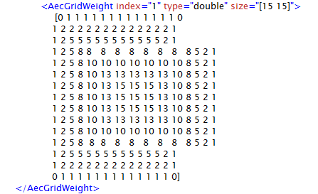
Editable transcription of the original 15×15 AecGridWeight example (225 values).
<AecGridWeight index="1" type="double" size="[15 15]">
  [0 1 1 1 1 1 1 1 1 1 1 1 1 1 0
   1 2 2 2 2 2 2 2 2 2 2 2 2 2 1
   1 2 5 5 5 5 5 5 5 5 5 5 5 2 1
   1 2 5 8 8 8 8 8 8 8 8 8 5 2 1
   1 2 5 8 10 10 10 10 10 10 10 8 5 2 1
   1 2 5 8 10 13 13 13 13 13 10 8 5 2 1
   1 2 5 8 10 13 15 15 15 13 10 8 5 2 1
   1 2 5 8 10 13 15 15 15 13 10 8 5 2 1
   1 2 5 8 10 13 15 15 15 13 10 8 5 2 1
   1 2 5 8 10 13 13 13 13 13 10 8 5 2 1
   1 2 5 8 10 10 10 10 10 10 10 8 5 2 1
   1 2 5 8 8 8 8 8 8 8 8 8 5 2 1
   1 2 5 5 5 5 5 5 5 5 5 5 5 2 1
   1 2 2 2 2 2 2 2 2 2 2 2 2 2 1
   0 1 1 1 1 1 1 1 1 1 1 1 1 1 0]
</AecGridWeight>
Figure 4-5 AEC weight parameters
It should be noted that some models of chip hardware support more block brightness statistics. In order to facilitate debugging, the weight of 15X15 is uniformly set in the debugging file, and the weight is expanded according to the number of blocks within the algorithm.
1.3.0.3 Step 3.Set AE exposure decomposition parameters
The exposure calculated by the AE control algorithm module needs to be decomposed into sensor exposure time component, sensor exposure gain component, ISP digital gain component and aperture component, and each component is set to the corresponding module to jointly realize the exposure setting to obtain the desired brightness image. The decomposition operation is completed by the parameters of the AecRoute module, and the parameter descriptions are described in Section 4.1.2. Different application scenarios need to set different AecRoutes: for daytime scenes, it is generally required to limit the exposure time and prioritize the gain to prevent motion smearing caused by excessive exposure time; For night scenes, it is generally required to prioritize the adjustment of the exposure time and then adjust the exposure gain in order to improve the signal-to-noise ratio of the picture and improve the brightness at night.
1.3.0.4 Step 4.Set the AE target brightness value
Linear exposure mode recommends turning on the dynamic target brightness function to meet the needs of different brightness scenes. The target brightness setting of linear mode involves DySetpoint, ToleranceIn/ToleranceOut, BackLightCtrl, OverExpCtrl parameters, etc., and the description of each parameter is detailed in Section 4.1.2. It is required to be suitable for indoor static scenes, and there is no large-scale overexposure. The environment transitions from light to dark, and the brightness can transition too smoothly.
HDR exposure mode, depending on the mode of exposure ratio and StrategyMode, the debugging steps of the target luminance value are also different. According to the exposure ratio mode and StrategyMode, adjust the target brightness parameter to the debug parameter module of the corresponding frame. The long-frame target brightness parameters involve LSetPoint and TargetLLLuma, which represent the global target brightness and the dark area target brightness, respectively. The target brightness parameter of the medium frame involves MSetPoint, which represents the global target brightness of the medium frame; The short frame target brightness involves SSetPoint and TargetHLLuma, which represent the global target brightness of the short frame and the target brightness of the highlight area, respectively. The description of each parameter is described in Section 4.1.2.
1.3.0.5 Step 5.Set AE convergence and response speed
The adjustment of AE convergence and response speed affects the exposure response speed, convergence speed and smoothness of the adjustment process. The parameters involved in this step include AecRunInterval, AecSpeed, AecDelayFrmNum, and the description of each parameter is described in Section 4.1.2. In indoor static scenes, the lights can be turned on and off to detect the convergence speed when the light changes sharply. Faster convergence can cause unsmooth transitions or overshoot when changing brightness slowly, so trade-offs are required.
2. 4.2 NR & SHARP
The ISP Denoising module consists of 4 modules: Bayernr 2D, Bayernr 3D, YNR and CNR.
The ISP sharpening module contains a SHARP module.
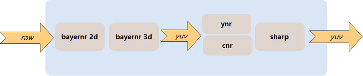
Block diagram of the NR pipeline
It is recommended to carry out noise debugging in the order of the pipeline, and each module debugging needs to consider the mutual influence and comprehensive effect of the previous and subsequent effects of the module.
During noise debugging, the effects of each step need to be viewed in order to clarify the impact of each step on denoising.
To view the Bayernr2D effect, you need to compare the undenoised original image with only the Bayernr2D effect open.
If you want to view the YNARR effect, you need to compare the Bayernr3D output with the image that has only been YNR but SHARP turned off.
And so on.
RV1106 differs from RK3588 on Pipe Line in the following ways:
1: Advance bayer3dnr to before bayer2dnr.
2: Bayer3DNR’s BayE3D Gain instructs Bayer2DNR to set different denoising forces for moving and stationary areas.
3: The YNR, CNR, SHARP module will set different denoise intensity for the motion and stationary areas according to the local gain module.
2.1 4.2.1 Bayer2dnr
2.1.1 4.2.1.1 Feature description
The Bayernr 2D module is mainly a module for spatial noise reduction of RAW data. The module will determine whether it is HDR mode, and convert the denoising strength to reduce the noise of the long and short frames of HDR at the same time.
The tuning process requires the noise variance of the RAW data to be calibrated to obtain the corresponding calibration data.
Based on the noise calibration results, the denoising module establishes a denoising model that is more in line with the noise characteristics.
Support two kinds of noise calibration and noise parameters for high signal-to-noise ratio and low signal-to- noise ratio respectively.
For example, CIS that supports Dual convertion gain DCG, high conversion gain (HCG) for high signal-to-noise mode, and low conversion gain (HCG) for low signal-to-noise mode.
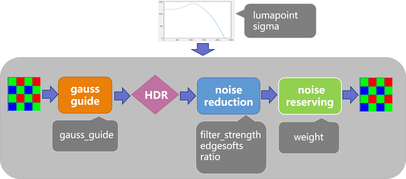
Bayernr2D block diagram
2.1.2 4.2.1.2 Key parameters
| Parameter name |
Parameter type |
Brief description |
|---|---|---|
| enable | Debug parameter |
Frequently debugged parameter |
| SNR_Mode | Mode parameter |
DCG mode corresponds to high and low signal-to-noise ratio mode |
| Sensor_Mode | Mode parameter |
sensor dcg mode |
| ISO | Debug parameter |
Frequently debugged parameter |
| lumapoint | Calibration Data |
The calibration tool generates parameter |
| sigma | Calibration Data |
The calibration tool generates parameter |
| gauss_guide | Debug parameter |
Frequently debugged parameter |
| filter_strength | Debug parameter |
Frequently debugged parameter |
| edgesofts | Debug parameter |
Infrequently debugged parameter |
| ratio | Debug parameter |
Frequently debugged parameter |
| weight | Debug parameter |
Frequently debugged parameter |
| pix_diff | Debug parameter |
Infrequent debugging parameters, not open in the tool interface for the time being, and open in the future |
| diff_thld | Debug parameter |
Infrequent debugging parameters, not open in the tool interface for the time being, and open in the future |
2.1.2.1 enable:
【Description】
Different pixel brightness corresponds to different noise sigma curve points. A total of 16 points.
2.1.2.2 SNR_Mode
【Description】
LCG and HCG correspond to different noise modes.
HSNR corresponds to HCG, and LSNR corresponds to LCG mode.
2.1.2.3 Sensor_Mode
【Description】
HCG and LCG modes supported by Sensor, if DCG mode is not supported, LCG parameters are used by default.
2.1.2.4 ISO
【Description】
Different ISO gears, corresponding to different debugging parameters. Currently only 13 gears are supported.
2.1.2.5 filter_strength
【Description】
Denoising force parameters. The value range [0, 16], the larger the value, the greater the denoising force.
2.1.2.6 gauss_guide
【Description】
Whether Gaussian guidance is enabled. 1: Enable. 0: Off.
2.1.2.7 lumapoint/sigma
【Description】
Calibration data, different Pixel brightness corresponds to different noise SIGMA curve points. A total of 16 points.
LumaPoint corresponds to the abscissa pixel brightness, value range [0, 65535]
sigma corresponds to the ordinate noise value curve, the value range [0, 65535];
2.1.2.8 edgesofts
【Description】
Affects airspace weights. The value range is [1, 16], and the default value is 1.
2.1.2.9 ratio
【Description】
Soft threshold weights. The value range is [0, 1.0]. The smaller the value, the greater the denoising force.
The value range is [0, 1], and the default value is 0.01.
2.1.2.10 weight
【Description】
The greater the value of the filter output, the greater the denoising force.
The value range is [0, 1], and the default value is 0.5.
2.1.2.11 pix_diff
【Description】
The parameters are not frequently debugged, and they are not open in the tool interface for the time being, and will be opened in the future.
A 5x5 window pixel difference threshold for bilateral filtering, with a default value of 0x3fff.
2.1.2.12 diff_thld
【Description】
The parameters are not frequently debugged, and they are not open in the tool interface for the time being, and will be opened in the future.
The square difference threshold for the calculation of Euclidean distances for bilateral filtering is 0x3ff by default.
2.1.3 4.2.1.3 Debugging Steps
During debugging: Disable modules such as Bayernr3D, Ynr, CNR, and Sharp.
Bayernr2D suppresses high-frequency noise that affects image detail and noise morphology. When the force is high, the noise particles become low-frequency and the details become less.
Adjust the velocity of bayernr2D to balance noise and loss of detail.
At low ISO, the overall noise cancellation is smaller, the filter_strength is smaller, and the weight is smaller.
Under high ISO, it is recommended to gradually increase the intensity appropriately, filter_strength is larger, and the weight is larger.
2.2 4.2.2 BayerTnr
2.2.1 4.2.2.1 Functional description
This module performs time-domain denoising and soft-threshold denoising on images in the RAW domain.
The current frame and IIR frame data will be divided into low-frequency layers and high-frequency layers for processing and noise reduction.
The tuning data for this module requires the same calibration data as for the Bayernr 2D module.
Based on the noise calibration results, the denoising module establishes a denoising model that is more in line with the noise characteristics.
Support two noise calibrations and noise parameters for high and low SNR, respectively.
For example, a CIS that supports Dual convertion gain (DCG) mode, high conversion gain (HCG) corresponds to a high signal-to-noise ratio mode, and low conversion gain (HCG) corresponds to a low signal-to-noise ratio mode.
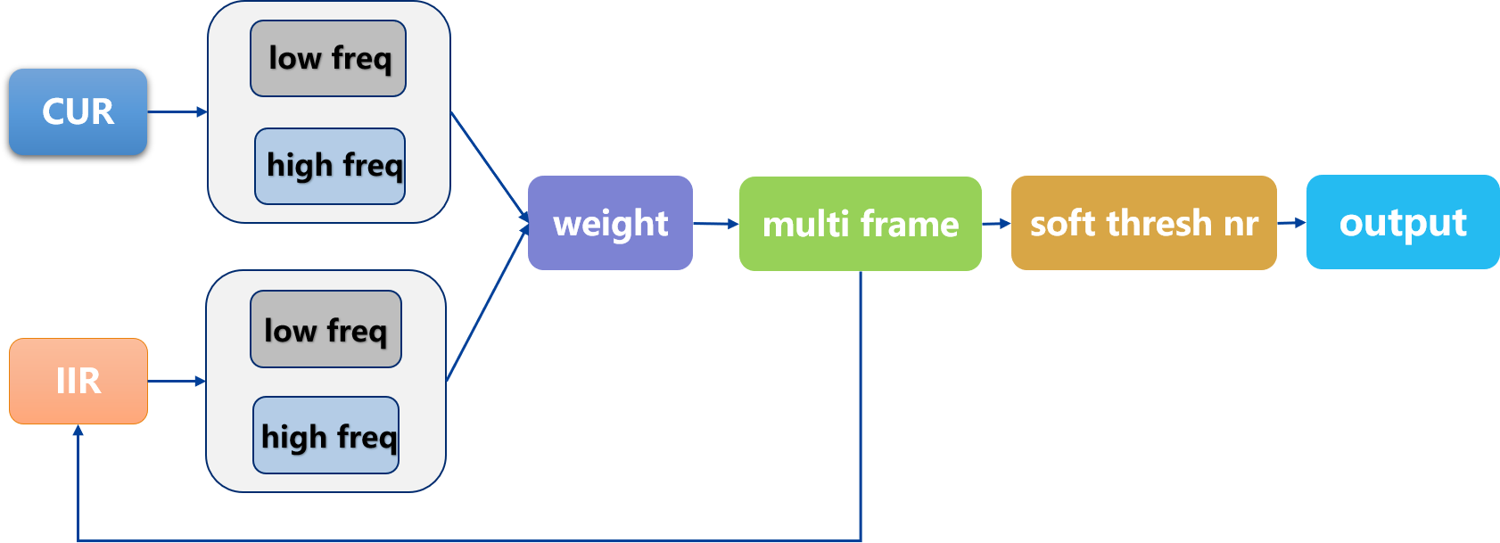
bayernr3d框图
2.2.2 4.2.2.2 Key Parameters
| Parameter name | Parameter type |
Brief description |
|---|---|---|
| Enable | Debug parameter |
Frequently debugged parameter |
| SNR_Mode | Mode parameter |
DCG mode corresponds to high and low signal- to-noise ratio mode |
| sensor_Mode | Mode parameter |
sensor dcg mode |
| iso | Debug parameter |
Frequently debugged parameter |
| thumbds | Debug parameter |
Infrequently debugged parameter |
| lo_enable | Debug parameter |
Frequently debugged parameter |
| hi_enable | Debug parameter |
Frequently debugged parameter |
| lo_med_en、lo_gsbay_en、 lo_gslum_en |
Debug parameter |
Infrequently debugged parameter |
| hi_med_en、hi_gslum_en | Debug parameter |
Infrequently debugged parameter |
| hi_wgt_comp | Debug parameter |
Infrequently debugged parameter |
| clipwgt | Debug parameter |
Infrequently debugged parameter |
| global_pk_en | Debug parameter |
Infrequently debugged parameter |
| global_pksq | Debug parameter |
Infrequently debugged parameter |
| hidif_th | Debug parameter |
Infrequently debugged parameter |
| lo_filter_strength | Debug parameter |
Frequently debugged parameter |
| hi_filter_strength | Debug parameter |
Frequently debugged parameter |
| softwgt | Debug parameter |
Frequently debugged parameter |
| Parameter name | Parameter type |
Brief description |
|---|---|---|
| lumapoint / sigm | Calibration Data |
The calibration tool generates parameter |
| lumapoint2 / lo_sigma | Calibration Data |
The calibration tool generates parameter |
| lumapoint2 / hi_sigma | Calibration Data |
The calibration tool generates parameter |
2.2.2.1 Enable:
【Description】
Bayernr3d module enable bit, 0: off, 1: on.
2.2.2.2 SNR_Mode
【Description】
LCG and HCG correspond to different noise patterns. HSNR corresponds to HCG, and LSNR corresponds to LCG mode.
2.2.2.3 sensor_Mode
【Description】
If the Sensor does not support DCG mode, the LCG parameter is used by default.
2.2.2.4 ISO
【Description】
Different ISO gears, corresponding to different debugging parameters. Currently, only 13 gears are supported.
2.2.2.5 thumbds
【Description】
Downsampling ratio. No debugging is required, the default value is 8.
2.2.2.6 lo_enable
【Description】
The low-frequency movement determines whether it is open or not, 1 opens, 0 closes. It is turned on by default.
2.2.2.7 hi_enable
【Description】
High-frequency motion judgment whether to open, 1 open, 0 off. It is turned on by default.
2.2.2.8 lo_med_en、lo_gsbay_en、lo_gslum_en
【Description】
Internal low-frequency sub-module switch, 1 on, 0 off. It is turned on by default.
2.2.2.9 hi_med_en、hi_gslum_en
【Description】
Internal high-frequency submodule switch, 1 on, 0 off. It is turned on by default.
2.2.2.10 hi_wgt_comp
【Description】
The proportional coefficient value of the superposition weight compensation is only useful when the high frequency is turned on;
The default value is 0.16, and the value range is [0.0, 1.0].
2.2.2.11 clipwgt
【Description】
The weight limit value of the image overlay.
The default value is 0.03215, and the value range is 0.0, 1.0.
2.2.2.12 global_pk_en
【Description】
Whether to use global PK for time domain denoising, 1 is used, 0 is not used.
At present, only 0.
2.2.2.13 global_pksq
【Description】
The square value of the global pk, which is used when the global_pk_en is 1.
The default value is 1024, and the value range is [0, 268435455].
2.2.2.14 hidif_th
【Description】
High-frequency difference threshold.
The default value is 32767, and the value range is 0, 65535.
2.2.2.15 lo_filter_strength
【Description】
High-frequency exercise determines strength. Ultimately, it affects Hi Sigma, which in turn affects the denoising intensity in the time domain.
The default value is 1, and the value range is [0.0, 16.0].
2.2.2.16 hi_filter_strength
【Description】
High-frequency exercise determines strength. Ultimately, it affects Hi Sigma, which in turn affects the denoising intensity in the time domain.
The default value is 1, and the value range is [0.0, 16.0].
2.2.2.17 softwgt
【Description】
Soft threshold weights. The higher the value, the more noise is retained.
The value range is 0.0 1.0, and the default value is 0.
2.2.2.18 lumapoint / sigma
【Description】
The value of the noise curve corresponding to the different brightness of the pixels. A total of 16 points.
LumaPoint corresponds to the brightness of pixels, with a value range of [0, 65535];
The sigma corresponds to the noise curve value in the range [0, 65535].
2.2.2.19 lumapoint2 / lo_sigma
【Description】
The value of the noise curve corresponding to the different brightness of the pixels. A total of 16 points.
lumapoint2 corresponds to the brightness of the pixel, and the value range is [0, 65535];
lo_sigma corresponds to the noise curve value, and the value range is [0, 65535].
2.2.2.20 lumapoint2 / hi_sigma
【Description】
The value of the noise curve corresponding to the different brightness of the pixels. A total of 16 points.
lumapoint2 corresponds to the brightness of the pixel, and the value range is [0, 65535];
hi_sigma corresponds to the noise curve value, and the value range is [0, 65535].
2.2.3 4.2.2.3 Debugging Steps
Close the bayernr2d, ynr, cnr, sharp modules
Adjust filter_strength, lo_clipwgt, hi_clipwgt parameters to balance denoising and smearing levels.
Normal time-domain multi-frame overlay denoising does not affect the noise pattern.
However, after multiple frames are superimposed, there is also a soft threshold processing in Bayernr3D, so it will affect the noise pattern.
The stronger the soft threshold processing, the lower the frequency of the noise particles.
2.2.4 4.2.2.3 Debugging steps
When debugging: open bayernr3d, close ynr, cnr, sharp and other modules.
Bayernr2D suppresses high-frequency noise, which affects image detail and noise morphology. When the force is high, the noise particles become low frequency and the details become less.
Adjust the dynamics of bayernr2D to balance noise and loss of detail.
At low ISO, the overall denoising force is smaller, the filter_strength is smaller, and the weight is smaller.
Under high ISO, it is recommended to increase the intensity appropriately and gradually, filter_strength larger and the weight larger.
According to the GAIN value of the motion area, the mapping table of the gain_adj is adjusted to increase the denoising intensity of the motion area.
2.3 4.2.3 YNR
2.3.1 4.2.3.1 Feature description
The module performs denoising and other processing of image brightness signals on the YUV domain. The module will use the previous frame downsampled image and the current frame image to perform bilateral denoising, soft threshold denoising, edge filtering, and other processing.
YNR will use the local noise size recorded by the GAIN module to denoise different areas of the local.
YNR will also set different denoising efforts in the radial direction with the center of the image as the origin to solve the corner noise corresponding to the LSC.
Based on the noise calibration results, the denoising module establishes a denoising model that is more in line with the noise characteristics.
Support two kinds of noise calibration and noise parameters for high signal-to-noise ratio and low signal-to- noise ratio respectively.
For example, CIS that supports Dual convertion gain DCG, high conversion gain (HCG) for high signal-to-noise mode, and low conversion gain (HCG) for low signal-to-noise mode.
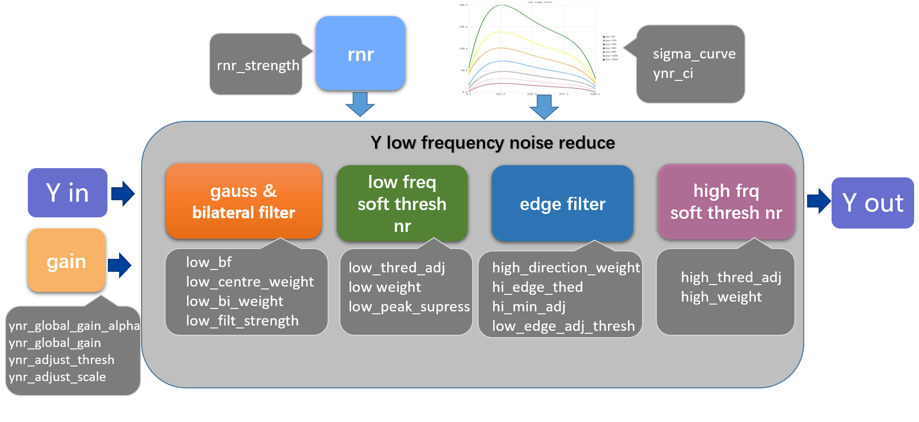
Fig. 4-2-3-1 YNNR functional block diagram
4.2.3.2 Key parameters
| Parameter name | Parameter type |
Brief description |
|---|---|---|
| Enable | Debug parameter |
Frequently debugged parameter |
| SNR_Mode | Mode parameter |
DCG mode corresponds to high and low signal-to-noise ratio mode |
| Sensor_Mode | Mode parameter |
sensor dcg mode |
| iso | Debug parameter |
Frequently debugged parameter |
| ynr_bft3x3_bypass | Debug parameter |
Infrequent debugging parameters, switch internal module |
| ynr_lbft5x5_bypass | Debug parameter |
Infrequent debugging parameters, switch internal module |
| ynr_lgft3x3_bypass | Debug parameter |
Infrequent debugging parameters, switch internal module |
| ynr_flt1x1_bypass | Debug parameter |
Infrequent debugging parameters, switch internal module |
| ynr_sft5x5_bypass | Debug parameter |
Infrequent debugging parameters, switch internal module |
| ynr_global_gain_alpha | Debug parameter |
Infrequently debugged parameter |
| ynr_global_gain | Debug parameter |
Infrequently debugged parameter |
| ynr_adjust_thres | Debug parameter |
Frequently debugged parameter |
| ynr_adjust_scale | Debug parameter |
Frequently debugged parameter |
| rnr_strength | Debug parameter |
Frequently debugged parameter |
| low_bf | Debug parameter |
Frequently debugged parameter |
| low_thred_adj | Debug parameter |
Frequently debugged parameter |
| low_peak_supress | Debug parameter |
Frequently debugged parameter |
| low_edge_adj_thresh | Debug parameter |
Frequently debugged parameter |
| Parameter name | Parameter type |
Brief description |
|---|---|---|
| low_lbf_weight_thresh | Debug parameter |
Frequently debugged parameter |
| low_center_weight | Debug parameter |
Frequently debugged parameter |
| low_dist_adj | Debug parameter |
Frequently debugged parameter |
| low_weight | Debug parameter |
Frequently debugged parameter |
| low_filt_strength | Debug parameter |
Frequently debugged parameter |
| low_bi_weight | Debug parameter |
Frequently debugged parameter |
| base_filter_weight | Debug parameter |
Infrequently debugged parameter |
| high_thred_adj | Debug parameter |
Frequently debugged parameter |
| high_weight | Debug parameter |
Frequently debugged parameter |
| high_direction_weight | Debug parameter |
Infrequently debugged parameter |
| hi_min_adj | Debug parameter |
Frequently debugged parameter |
| hi_edge_thed | Debug parameter |
Frequently debugged parameter |
| sigma_curve | Calibration Data |
The calibration tool generates parameter |
| ynr_ci | Calibration Data |
The calibration tool generates parameter |
2.3.1.1 Enable:
【Description】
The ynr module enables the switch, 1: module on, 0: module off.
2.3.1.2 SNR_Mode
【Description】
LCG and HCG correspond to different noise modes.
HSNR corresponds to HCG, and LSNR corresponds to LCG mode.
2.3.1.3 Sensor_Mode
【Description】
HCG and LCG modes supported by Sensor, if DCG mode is not supported, LCG parameters are used by default.
2.3.1.4 ISO
【Description】
Different ISO gears, corresponding to different debugging parameters. Currently only 13 gears are supported.
2.3.1.5 ynr_bft3x3_bypass,ynr_lbft5x5_bypass,ynr_lgft3x3_bypass,ynr_flt1x1_bypass, ynr_sft5x5_bypass
【Description】
The module is a sub-module bypass function. 0: Function enabled. 1: Function bypass.
In general, all submodules are enabled and these values are set to 0.
2.3.1.6 ynr_global_gain_alpha/ynr_global_gain
【Description】
Ynr denoising local mode and global mode interpolate force configuration.
Generally, the default value is used, no configuration, and all use the local gain method.
Formula: Gain = (global_gain_alphaglobal_gain+(8-global_gain_alpha)local_gain)>>3
Global gain alpha takes the value range [0.0 1.0], and the default value is 0.
Global gain takes the value range [0.0 64.0]. Default value 1.
2.3.1.7 ynr_adjust_thresh /ynr_adjust_scale
【Description】
Denoise force control for noise greater than the threshold ynr_adjust_thresh.
The design is about to think that the noise in the moving area is relatively large, and set an appropriate threshold to increase the denoising intensity of the YYR in the moving area.
ynr_adjust_thresh, the value range is [0.0, 1.0], and the default value is 1.
ynr_adjust_scale, the value range is [0, 16.0], and the default value is 1.
2.3.1.8 rnr_strength
【Description】
In the center of the image, different denoising forces are set in the direction of the radius r of the circle.
It is mainly configured for the noise of LSC.
The value range is [0, 16.0], and the default value is 1.
2.3.1.9 low_bf
【Description】
Bilateral filtering force parameters.
The first line is the original 3x3 bilateral filtering force, the larger the value, the stronger the denoising.
The value range is [0.01, 32], and the default value is 1.
The second line is the 5x5 bilateral filtering force of the previous frame, the larger the value, the stronger the denoising.
The value range is [0.01, 32], and the default value is 1.
2.3.1.10 low_thred_adj
【Description】
The higher the value of the low-frequency soft threshold, the greater the low-frequency noise reduction force.
The value range is [0, 31], and the default value is 0.5.
2.3.1.11 low_peak_supress
【Description】
Controls the force with which isolated noise is removed, the smaller the value, the greater the denoising force.
The value range is [0, 1], and the default value is 0.5.
2.3.1.12 low_edge_adj_thresh
【Description】
The threshold of the adjustment factor for edge detection of the small plot, which is used to limit the maximum value that can be taken by the adjustment factor.
The smaller the value, the greater the denoising force and the blurrier the image. The value range [0, 1023] integer, default value 7.
2.3.1.13 low_lbf_weight_thresh
【Description】
The weight used to limit the 5x5 bilateral filtering, the higher the value, the weaker the low-frequency noise reduction.
The value range is [0.0, 1.0]. The default value is 0.25.
2.3.1.14 low_center_weight
【Description】
The weight of the center point during 5x5 bilateral filtering, the smaller the value, the stronger the noise reduction.
The value range is [0,1], and the default value is 0.5.
2.3.1.15 low_dist_adj
【Description】
Bilateral filter distance weight adjustment factor. The smaller the value, the stronger the denoising.
The value range is [0, 127.0], and the default value is 8.0.
2.3.1.16 low_weight
【Description】
The weight of the low-frequency denoising result, the larger the value, the greater the low-frequency noise reduction force.
The value range is [0, 1], and the default value is 0.5.
2.3.1.17 low_filt_strength
【Description】
The first row performs Gaussian filtering on the original graph with the filter kernel weight.
The value range is [0,1.0], and the default value is 0.7.
The second line performs the filter kernel weights of Gaussian filtering on the results of bilateral filtering.
The value range is [0,1.0], and the default value is 0.85.
2.3.1.18 low_bi_weight
【Description】
The first bilateral filter weight used in soft threshold processing, the higher the value, the greater the noise reduction.
The value range is [0, 1], and the default value is 0.3.
2.3.1.19 base_filter_weight
【Description】
The coefficient of the directional filter. Adjustments are generally not necessary.
2.3.1.20 high_thred_adj
【Description】
The higher the value, the greater the intensity of high-frequency noise reduction.
The value range is 0, 31.0, and the default value is 1.0.
2.3.1.21 high_weight
【Description】
high-frequency denoising weight, note that this value represents the proportion of the high-frequency components that are retained,
The lower the value, the stronger the noise reduction. The default value is 0.78.
2.3.1.22 high_direction_weight
【Description】
The weights in each direction are set, the greater the value in a certain direction, Indicates that the noise reduction is stronger along that direction.
2.3.1.23 hi_min_adj
【Description】
The ratio of all variance values minus the smallest variance value, the larger the value, the sharper the edges.
The value range is 0.0, 1.0, and the default value is 0.9
2.3.1.24 hi_edge_thed
【Description】
The smaller the threshold, the greater the high-frequency noise reduction.
An integer in the range of 0, 255, with the default value of 100.
2.3.1.25 sigma_curve
【Description】
Noise sigma curve.
2.3.1.26 ynr_ci
【Description】
Influencing the impact factor of noise sigma. The higher the value, the greater the noise sigma and the stronger the noise removal.
The first line affects the low-frequency sigma.
The second line affects high-frequency sigma.
2.3.1.27 hi_center_weight
【Description】
The higher the weight of the high-frequency center point, the weaker the noise reduction.
The value range is [0, 1], and the default value is 0.8.
2.3.2 4.2.3.3 Debugging steps
Close the SHARP module.
Adjust the low-frequency denoising parameters such as Lob, Lothred Adi, Lowitt, Lobivet, etc.,
Adjust the high-frequency denoising parameters such as Hewitt and Hesley Adi,
Adjust An_Strent to adjust the noise intensity of the corners.
Adjust Ian Adjast Sresh and Ian Adjast Skelle to adjust the noise in the moving area.
Overall balanced levels of noise reduction and loss of detail. The greater the denoising intensity, the more low- frequency the noise becomes.
2.4 4.2.4 CNR
2.4.1 4.2.4.1 Feature description
This module mainly focuses on color noise reduction for UV data. It is close to the UVNR module algorithm of RK ISP2X.
The image is mainly downsampled at different scales, and finally upsampled back to the scale of the original image.
The median filter is performed on the up-and-down sampling of each scale, and then the UV data is double-sided filtered, and the edge color noise is processed with reference to the gradient of y, and finally the output is interpolated with the undenoised image.
Support sharpening parameter settings for high signal-to-noise ratio and low signal-to-noise ratio respectively.
For example, a CIS that supports Dual convertion gain (DCG) mode, high conversion gain (HCG) corresponds to a high signal-to-noise ratio mode, and low conversion gain (HCG) corresponds to a low signal-to-noise ratio mode.
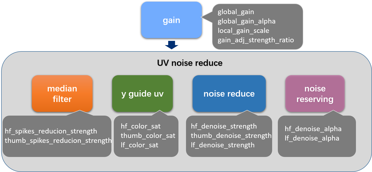
Fig. 4-2-3-1 CNR functional block diagram
2.4.2 4.2.4.2 Key parameters
| Parameter name | Parameter type |
Brief description |
|---|---|---|
| Enable | Debug parameter |
Frequently debugged parameter |
| SNR_Mode | Mode parameter |
DCG mode corresponds to high and low signal- to-noise ratio mode |
| Sensor_Mode | Mode parameter |
sensor dcg mode |
| iso | Debug parameter |
Frequently debugged parameter |
| hf_bypass | Debug parameter |
Infrequent debugging parameters, switch internal module |
| lf_bypass | Debug parameter |
Infrequent debugging parameters, switch internal module |
| global_gain | Debug parameter |
Infrequently debugged parameter |
| global_gain_alpha | Debug parameter |
Infrequently debugged parameter |
| global_gain_scale | Debug parameter |
Infrequently debugged parameter |
| gain_adj_strength_ratio | Debug parameter |
Frequently debugged parameter |
| color_sat_adj | Debug parameter |
Frequently debugged parameter |
| color_sat_adj_alpha | Debug parameter |
Frequently debugged parameter |
| hf_spikes_reducion_strength | Debug parameter |
Frequently debugged parameter |
| hf_denoise_strength | Debug parameter |
Frequently debugged parameter |
| hf_color_sat | Debug parameter |
Frequently debugged parameter |
| hf_denoise_alpha | Debug parameter |
Frequently debugged parameter |
| hf_bf_wgt_clip | Debug parameter |
Frequently debugged parameter |
| Parameter name | Parameter type |
Brief description |
|---|---|---|
| thumb_spikes_reducion_strength | Debug parameter |
Frequently debugged parameter |
| thumb_denoise_strength | Debug parameter |
Frequently debugged parameter |
| thumb_color_sat | Debug parameter |
Frequently debugged parameter |
| lf_denoise_strength | Debug parameter |
Frequently debugged parameter |
| lf_color_sat | Debug parameter |
Frequently debugged parameter |
| lf_denoise_alpha | Debug parameter |
Frequently debugged parameter |
| kernel_5x5 | Debug parameter |
Infrequently debugged parameter |
2.4.2.1 Enable
【Description】
The module switch is enabled. 1: Module open, 0: Module off.
2.4.2.2 SNR_Mode
【Description】
LCG and HCG correspond to different noise modes. HSNR corresponds to HCG, and LSNR corresponds to LCG mode.
2.4.2.3 Sensor_Mode
【Description】
HCG and LCG modes supported by Sensor, if DCG mode is not supported, LCG parameters are used by default.
2.4.2.4 ISO
【Description】
Different ISO gears, corresponding to different debugging parameters. Currently only 13 gears are supported.
2.4.2.5 hf_bypass
【Description】
High-frequency noise reduction bypass. 0: No bypass, 1: bypass.
2.4.2.6 lf_bypass
【Description】
Low-frequency noise reduction bypass.0:No bypass, 1:bypass.
2.4.2.7 global_gain/global_gain_alpha
【Description】
CNR denoising local mode and global mode interpolation strength configuration.
Generally, the default value is used, and the local gain method is used without configuration.
Formula: Gain=(global_gain_alphaglobal_gain+(8-global_gain_alpha)local_gain)>>3
The value range of global gain alpha is [0.0 1.0], and the default value is 0.
The value range of global gain is 0.0 to 64.0, and the default value is 1.
2.4.2.8 local_gain_scale
【Description】
To amplify the CNR denoising strength, the default value is generally used, and it is not easy to adjust.
The value range is 0, 128, and the default value is 1.
2.4.2.9 gain_adj_strength_ratio
【Description】
Adjust the filter intensity based on the local gain value. The lower the value, the stronger the noise removal.
The value range is [1, 255], the default value is 255.
2.4.2.10 color_sat_adj
【Description】
The UV ratio of bilateral filtering based on gradient adjustment, 1~255. The smaller the value, the better the color noise removal.
Valid values: [1, 255]. The default value is 40.
2.4.2.11 color_sat_adj_alpha
【Description】
color_sat_adj Adjusted ratio. The higher the value, the better the color noise removal.
The value range is 0, 1.0. The default value is 0.8.
2.4.2.12 hf_spikes_reducion_strength
【Description】
High frequency median filter intensity. The higher the value, the stronger the median filtering.
The value range is 0, 1.0. The default value is 0.5.
2.4.2.13 hf_denoise_strength
【Description】
High-frequency bilateral filter intensity. The higher the value, the better the color noise removal.
The value range is [1, 1023]. The default value is 10.
2.4.2.14 hf_color_sat
【Description】
UV scale factor for high-frequency bilateral filtering. The lower the value, the more the color saturation drops.
The value range is 0.0, 7.9. The default value is 1.5.
2.4.2.15 hf_denoise_alpha
【Description】
The weight of the center point of the high-frequency bilateral filter.
Valid values: 0.0, 1.0. The default value is 0.
2.4.2.16 hf_bf_wgt_clip
【Description】
Minimum denoising at high frequencies. The higher the value, the stronger the denoising.
The value range is 0, 255. The default value is 0.
2.4.2.17 thumb_spikes_reducion_strength
【Description】
Thumbnail median filter intensity. The higher the value, the stronger the median filtering.
Valid values: 0.0, 1.0. The default value is 0.5.
2.4.2.18 thumb_denoise_strength
【Description】
Thumbnail bilateral filter intensity. The higher the value, the better the color noise removal.
The value range is [1, 1023]. The default value is 8.
2.4.2.19 thumb_color_sat
【Description】
The UV scale factor of thumbnail double-sided filtering, the more color saturation drops.
The value range is 0.0, 7.9. Default value is 4.
2.4.2.20 lf_denoise_strength
【Description】
Low-frequency bilateral filtering intensity. The higher the value, the better the color noise removal.
The value range is [1, 1023]. The default value is 8.
2.4.2.21 lf_color_sat
【Description】
The UV ratio of low-frequency bilateral filtering is due to. The lower the value, the more the color saturation drops.
The value range is 0.0, 7.9. Default value is 4.
2.4.2.22 lf_denoise_alpha
【Description】
The weight of the center point of the low-frequency bilateral filter.
Valid values: 0.0, 1.0. The default value is 0.5.
2.4.2.23 kernel_5x5
【Description】
5x5 bilateral filter core.
2.4.3 4.2.4.3 Debugging steps
Close the SHARP module.
Adjust parameters such as denoise_strength, denoise_alpha and color_sat of each layer.
Control the removal of high- and low-frequency color noise, weighing for defects such as chroma staining and saturation reduction.
2.5 4.2.5 SHARP
2.5.1 4.2.5.1 Feature description
The Sharpen module is used to enhance the sharpness of the image, and the algorithm is close to that of rk isp2x.
It mainly extracts high-frequency data, then pre-filters, sharpens enhancement and noise suppression, and finally superimposes the output with the interpolation of the unsharpened original image.
Support sharpening parameter settings for high SNR and low SNR noise modes respectively.
For example, a CIS that supports Dual convertion gain (DCG) mode, high conversion gain (HCG) corresponds to a high signal-to-noise ratio mode, and low conversion gain (HCG) corresponds to a low signal-to-noise ratio mode.
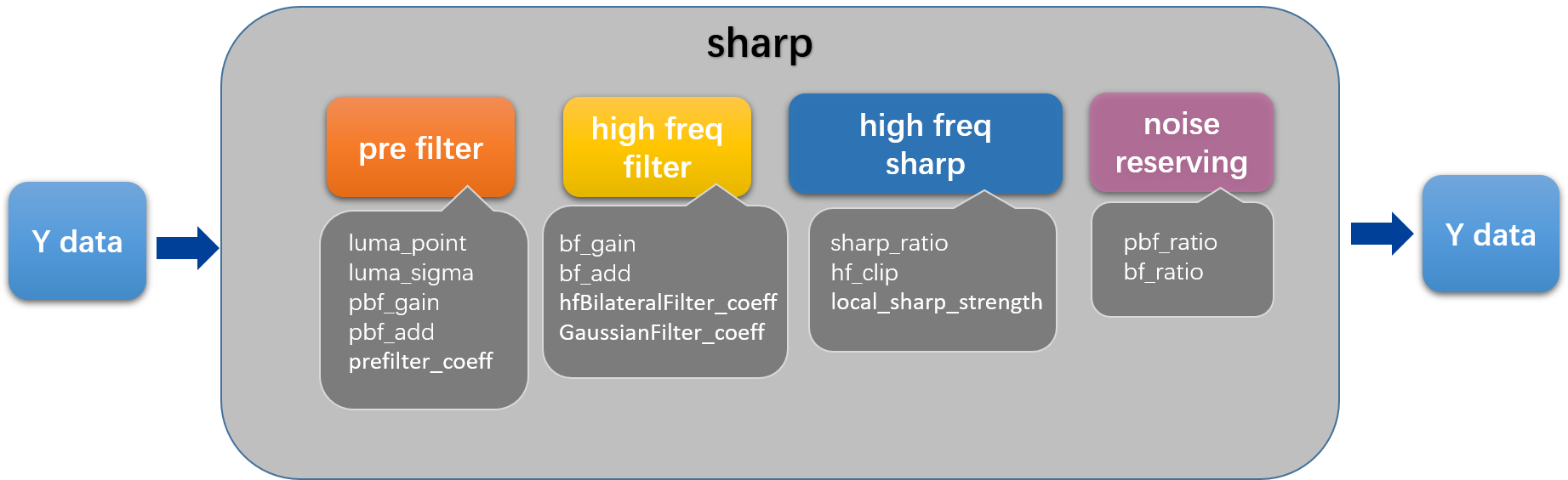
Figure 4-2-5-1 Block diagram of SHARP functions
2.5.2 4.2.5.2 Key parameters
| Parameter name | Parameter type |
Brief description |
|---|---|---|
| Enable | Debug parameter |
Frequently debugged parameter |
| SNR_Mode | Mode parameter |
DCG mode corresponds to high and low signal-to- noise ratio mode |
| Sensor_Mode | Mode parameter |
sensor dcg mode |
| iso | Debug parameter |
Frequently debugged parameter |
| pbf_gain | Debug parameter |
Frequently debugged parameter |
| pbf_add | Debug parameter |
Frequently debugged parameter |
| pbf_ratio | Debug parameter |
Frequently debugged parameter |
| gaus_ratio | Debug parameter |
Frequently debugged parameter |
| sharp_ratio | Debug parameter |
Frequently debugged parameter |
| bf_gain | Debug parameter |
Frequently debugged parameter |
| bf_add | Debug parameter |
Frequently debugged parameter |
| luma_point / luma_sigma | Debug parameter |
Frequently debugged parameter |
| luma_point / hf_clip | Debug parameter |
Frequently debugged parameter |
| luma_point / local_sharp_strength |
Debug parameter |
Frequently debugged parameter |
| prefilter_coeff | Debug parameter |
Frequently debugged parameter |
| GaussianFilter_coeff | Debug parameter |
Frequently debugged parameter |
| hfBilateralFilter_coeff | Debug parameter |
Frequently debugged parameter |
2.5.2.1 Enable:
【Description】
The Sharp module enables the switch.
1: Module open, 0: Module off.
2.5.2.2 SNR_Mode
【Description】
LCG and HCG correspond to different noise modes. HSNR corresponds to HCG, and LSNR corresponds to LCG mode.
2.5.2.3 Sensor_Mode
【Description】
HCG and LCG modes supported by Sensor, if DCG mode is not supported, LCG parameters are used by default.
2.5.2.4 ISO
【Description】
Different ISO gears, corresponding to different debugging parameters. Currently only 13 gears are supported.
2.5.2.5 pbf_gain
【Description】
The pre-filtered sigma is multiplied by the ratio, the larger the value, the stronger the filtering, the less noise and less detail.
The value range is [0.0, 2.0], and the default value is 1.0.
2.5.2.6 pbf_add
【Description】
The offset of the pre-filtered sigma superposition, the larger the value, the stronger the filtering, the less noise, and less detail.
The value range is [0, 1023], and the default value is 0.
2.5.2.7 pbf_ratio
【Description】
Pre-filter fusion weights, the larger the value, the stronger the filtering, the smaller the noise, and less detail.
The value range is [0.0, 1.0], and the default value is 0.5.
2.5.2.8 gaus_ratio
【Description】
The guided image of high-frequency bilateral filtering is the result of the fusion of Gaussian filtering and the original image.
The larger the value, the greater the guiding weight of the Gaussian bilateral filter.
The value range is [0.0, 1.0], and the default value is 0.
2.5.2.9 sharp_ratio
【Description】
Sharpening strength, the higher the value, the stronger the sharpening.
Value range [0.0, 32], default value 6.
2.5.2.10 bf_gain
【Description】
The proportion of high-frequency bilateral filtering sigma multiplied, the larger the value, the stronger the filtering, the smaller the noise, and the less detail.
The value range is [0.0, 2.0], and the default value is 1.0.
2.5.2.11 bf_add
【Description】
Offset of high-frequency bilateral filtering sigma superposition. The larger the value, the stronger the filtering, the smaller the noise, and the less detail.
The value range is [0, 1023], and the default value is 0.
2.5.2.12 bf_ratio
【Description】
High-frequency bilateral filter fusion weights. The larger the value, the stronger the filtering, the smaller the noise, and the less detail.
The value range is [0.0, 1.0], and the default value is 0.5.
2.5.2.13 luma_point / luma_sigma
【Description】
Different pixel brightness corresponds to different noise SIGMA curves.
luma_point is the curve brightness value, the value range [0, 1023].
luma_sigma is the noise intensity value, the value range [0, 1023] .
2.5.2.14 luma_point / hf_clip
【Description】
Range of different pixel brightness high-frequency values clips.
The higher the value, the stronger the maximum allowable sharpening strength.
The value range is [0, 1023]. The default value is 256.
2.5.2.15 luma_point / local_sharp_strength
【Description】
Calculate the proportion of different pixel brightness, high frequency superposition weights.
The higher the value, the greater the high frequencies that allow for overlays and the sharper the image.
2.5.2.16 prefilter_coeff:
【Description】
Pre-filter operators.
2.5.2.17 GaussianFilter_coeff
【Description】
Gaussian filter operators.
2.5.2.18 hfBilateralFilter_coeff
【Description】
High-frequency bilateral filtering operator.
2.5.3 4.2.5.3 Debugging steps
Adjust sharp_ratio, local_sharp_strength, hf_clip, control the intensity of high-frequency edge enhancement.
Adjust the parameters of gaus_ratio, pbf_ratio, pbf_gain, pbf_add, bf_ratio, bf_gain, bf_add to reduce noise caused by sharpening, and to balance noise and sharpen details.
The Sharp module can enhance detail while suppressing noise, but ultimately it inevitably leads to an increase in overall noise.
3. 4.3 MERGE
3.1 4.3.1 Feature description
With this module, it is possible to adjust the proportion of long (medium) short frames used during compositing. The proportion of using a frame is determined by the combination of the overexposure weight and the motion weight of the frame, which is a product relationship, where the overexposure weight is determined by the overexposure curve and the motion weight is determined by the motion curve.
During the fusion process, the reference frame can be selected as a long frame or a short frame, corresponding to the long frame mode and short frame mode, respectively.
The overexposure curve is determined by two parameters, OECurve_smooth and OECurve_offset, in the two- frame mode, whether the overexposure is judged between the long frame and the short frame, and in the three- frame mode, whether the overexposure is judged between the long frame and the medium frame.
In the long frame mode, there are long frame and medium frame motion curves (determined by LM_smooth and LM_offset parameters) and medium frame and short frame motion curves (MS_smooth and MS_offset parameters), in the two-frame mode, only the middle frame and short frame motion curves take effect, and in the short frame mode, the curve is determined by the Coef, ms_thd0 and lm_thd0 parameters.
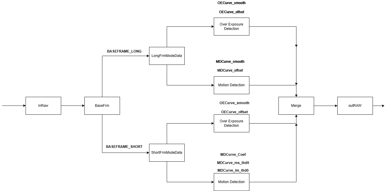
Merge block diagram
3.2 4.3.2 Key parameters
3.2.1 4.3.2.1 BaseFrm
【Description】
Represents the selection of a fiducial frame during the fusion process.
【Members】
| Member name | Description |
|---|---|
| BASEFRAME_LONG | Long frames are the base |
| BASEFRAME_SHORT | Short frames are the base |
【Precautions】
Using BASEFRAME_LONG and BASEFRAME_SHORT, the brightness is basically the same after fusion. The main differences are better motion smearing when using BASEFRAME_SHORT mode and better noise when using BASEFRAME_LONG mode.
When using BASEFRAME_LONG mode, the parameters in LongFrmModeData take effect, and when using BASEFRAME_SHORT mode, the parameters in ShortFrmModeData take effect.
3.2.2 4.3.2.2 ByPassThr
【Description】
Indicates the current module threshold of bypass, with a value range of [0,1]. When the percentage difference between the current ambient brightness and the ambient brightness of the previous frame is less than ByPassThr, the parameters of this module are not updated.
【Members】
【Precautions】
During debugging with the tool, write the value to 0, otherwise debugging may be invalid.
3.2.3 4.3.2.3 LongFrmModeData
【Description】
In long frame mode, merge parameter.
【Members】
| Member name | Description |
|---|---|
| OECurve | Overexposure curve parameters |
| MDCurve | Motion profile parameters |
| OECurve_damp | The smoothing coefficient of the change of the overexposure curve is the proportion of the current frame parameter, the value range is [0,1], and the default value is 0.9. |
| MDCurveLM_damp | The smoothing coefficient of the change of motion curve between long frames and medium frames is the proportion of the current frame parameter, the value range is [0,1], and the default value is 0.9. In HDR x2 mode, it does not take effect |
| MDCurveMS_damp | The smoothing coefficient of the change of the motion curve between the middle frame and the short frame is the proportion of the current frame parameter, the value range is [0,1], and the default value is 0.9. |
【Precautions】
3.2.3.1 4.3.2.3.1 EnableEachChn
【Description】
Single-channel overexposure detection switch. 0: Off, 1: On.
【Members】
【Precautions】
When there is a monochrome area in the picture that is overexposed, resulting in the monochrome overexposure area, it is recommended to turn it on when the noise is large after the merge.
3.2.3.2 4.3.2.3.2 OECurve
【Description】
In long frame mode, overexposure curve parameters.
【Members】
| Member Name |
Description |
|---|---|
| EnvLv | Overexposure curve parameter |
| EnvLv_len | EnvLv array length |
| Smooth | The slope of the overexposure curve can be ranged from [0,1], with a default value of 0.4 and an accuracy of 0.01 |
| Smooth_len | Smooth array length |
| Offset | The offset value of the overexposure curve ranges from [108,280], the default value is 210, and the accuracy is 0.1 |
| Offset_len | Offset array length |
【Precautions】
3.2.3.3 4.3.2.3.3 MDCurve
【Description】
In long frame mode, motion curve parameters.
【Members】
| Member Name | Description |
|---|---|
| MoveCoef | The degree of motion of the picture can be taken in the range of [0,1], where 0 represents complete stillness and 1 represents complete motion |
| MoveCoef_len | MoveBeef array length |
| LM_smooth | The slope of the motion curve between the long frame and the medium frame, the value range is [0,1], and the default value is 0.4. In HDR x2 mode, it does not take effect. |
| LM_smooth_len | LM_smooth array length |
| LM_offset | The offset value of the motion curve between the long frame and the medium frame can be [0.26,1], and the default value is 0.38. In HDR x2 mode, it does not take effect. |
| LM_offset_len | LM_offset array length |
| MS_smooth | The slope of the motion curve between the middle frame and the short frame, the value range is [0,1], and the default value is 0.4. |
| MS_smooth_len | MS_smooth array length |
| MS_offset | The offset value of the motion curve between the middle frame and the short frame can be [0.26,1], and the default value is 0.38. |
| MS_offset_len | MS_offset array length |
【Precautions】
MoveCoef: Since the current scene detection is not done, the amount of motion cannot be obtained, and the actual use is that MoveComeEf is equal to 1
3.2.4 4.3.2.4 ShortFrmModeData
【Description】
In short frame mode, merge parameter.
【Members】
| Member name | Description |
|---|---|
| OECurve | Overexposure curve parameters |
| MDCurve | Motion profile parameters |
| OECurve_damp | The smoothing coefficient of the change of the overexposure curve is the proportion of the current frame parameter, the value range is [0,1], and the default value is 0.9. |
| MDCurve_damp | The smoothing coefficient of the change of the motion curve is the proportion of the current frame parameter, the value range is [0,1], and the default value is 0.9. |
【Precautions】
3.2.4.1 4.3.2.4.1 OECurve
【Description】
In long frame mode, overexposure curve parameters.
【Members】
| Member Name |
Description |
|---|---|
| EnvLv | Overexposure curve parameter |
| EnvLv_len | EnvLv array length |
| Smooth | The slope of the overexposure curve can be ranged from [0,1], with a default value of 0.4 and an accuracy of 0.01 |
| Smooth_len | Smooth array length |
| Offset | The offset value of the overexposure curve ranges from [108,280], the default value is 210, and the accuracy is 0.1 |
| Offset_len | Offset array length |
【Precautions】
3.2.4.2 4.3.2.4.2 MDCurve
【Description】
In long frame mode, overexposure curve parameters.
【Members】
| Member Name |
Description |
|---|---|
| MoveCoef | The degree of motion of the picture can be taken in the range of [0,1], where 0 represents complete stillness and 1 represents complete motion |
| MoveCoef_len | MoveBeef array length |
| Coef | The default value is 0.05 and the accuracy is 0.0001 |
| Coef_len | Coef array length |
| ms_thd0 | The control coefficient for short and medium frames is in the range of [0,1], the default value is 0.0, and the accuracy is 0.1 |
| ms_thd0_len | ms_thd0 array length |
| lm_thd0 | The control coefficient of long and medium frames can be set to 0.0 and the accuracy is 0.1. In HDR x2 mode, it does not take effect. |
| lm_thd0_len | lm_thd0 array length |
【Precautions】
3.3 4.3.3 Debugging steps
Merge debugging mainly includes two parts: overexposure curve debugging and motion curve debugging.
3.3.1 4.3.3.1 Overexposure curve debugging
【Description】
The overexposure curve OECurve is determined by the OECurve_smooth and OECurve_offset (the curve is shown in the figure below), and at the same time, different overexposure curves are set under different Envlv.
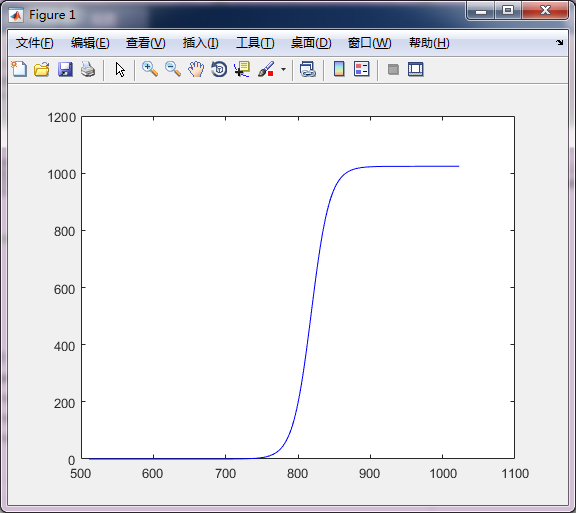
Schematic diagram of OECurve
【Members】
| Member name | Description |
|---|---|
| Smooth | Overexposure curve slope |
| Offset | Overexposure curve slope |
【Precautions】
1.Smooth:
Image-wise, this value represents smoothing of areas of long and short frame transitions: the smaller the value, the smoother the transition between the overexposed and non-overexposed areas, and the larger the transition area, and conversely, the more abrupt the transition between the overexposed and non-overexposed areas, but the smaller the transition area. In the figure below, the red curve represents the value of 0, the green curve represents the value of 0.4, and the blue curve represents the value of 1.
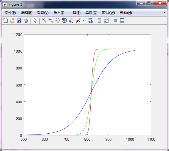
OECurve_smooth schematic
2.Offset:
Image-wise, this value represents the initial value of using short frames at overexposure. The smaller the value, the maximum weight is used for short frames.
Several special points: where 108 represents, the value of the overexposure curve set is all 1023, at this time, the weight used by the short frame is the largest, as shown in the yellow curve in the figure below; The value 128 represents that short frames may be used from the beginning of the brightness of 128, as shown in the blue curve in the figure below; 215 is the representative, 215 is the value represents that from the beginning of the brightness of 215, the short frame may be used, and just when it reaches 256, the weight of the short frame is exactly 1023, as shown in the green curve in the figure below; 280 is to represent that the overexposure curve value is all 0, and merge will not use short frames, as shown in the red curve in the following figure:
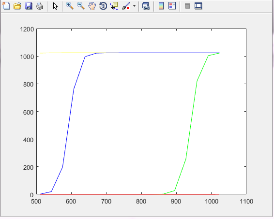
OECurve_offset schematic
3.3.2 4.3.3.2 Motion curve debugging in long frame mode
【Description】
The actual curve of the motion curve (MS_smooth and MS_offset, determined by two sets of parameters LM_smooth and LM_offset in long frame mode) is shown in the figure below.
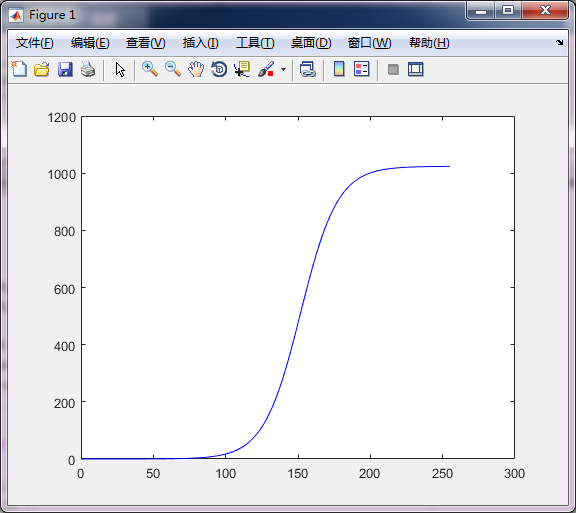
Schematic diagram of MDCurve
When the picture is moving, the weight needs to be reduced, so as to reduce the use of short frames, thereby reducing the ghosting caused by the movement. At the same time, different motion curves are set under different MoveCoef
【Members】
| Member name | Description |
|---|---|
| MS_smooth | Slope of the motion curve |
| MS_offset | Slope of the motion curve |
【Precautions】
1.MS_smooth:
This value indicates the smoothing of the transition area of short and medium frames: the smaller the value, the smoother the transition between the overexposed and nonexposed areas, and the larger the transition area, and conversely, the more abrupt the transition between the overexposed and nonexposed areas, but the smaller the transition area. In the figure below, the green curve represents the value of 0, the red curve represents the value of 0.4, and the blue curve represents the value of 1.
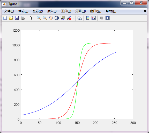
MDCurve_smooth schematic
2.MS_offset:
Image-wise, this value represents the initial value of using short frames at overexposure. The smaller the value, the maximum weight is used for short frames. The green curve represents a value of 0, the blue curve represents a value of 0.38, and the red curve represents a value of 1.
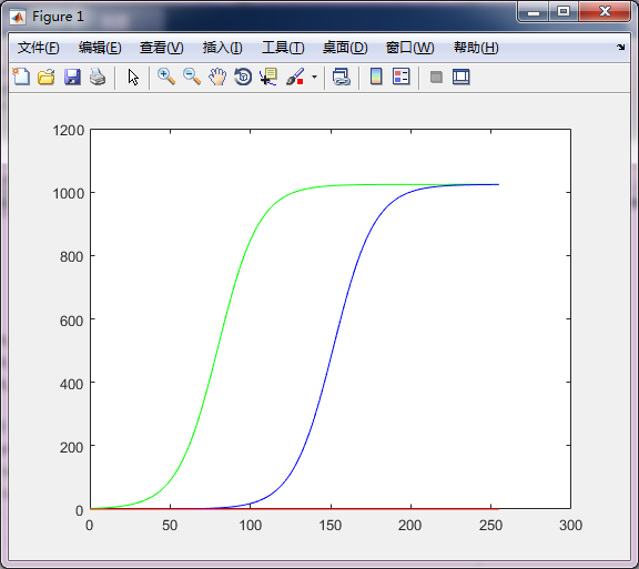
MDCurve_offset schematic
3.3.3 4.3.3.2 Motion curve debugging in short frame mode
【Description】
The actual curve of the motion curve (determined by Coef, ms_thd0, and lm_thd0 three parameters) in short frame mode is shown in the figure below.
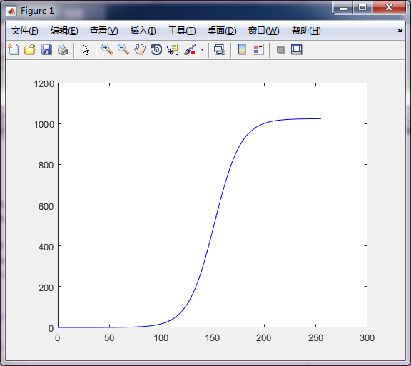
Schematic diagram of MDCurve
When the picture is moving, the weight needs to be reduced, so as to reduce the use of short frames, thereby reducing the ghosting caused by the movement. At the same time, different motion curves are set under different MoveCoef.
【Members】
| Member name |
Description |
|---|---|
| Coef | Control coefficient, value range [0,1], default value is 0.05, accuracy 0.0001 |
| ms_thd0 | The medium and short frame control coefficient has a value range of [0,1], and the default value is 0.0 and the accuracy is 0.1. |
| lm_thd0 | The long medium frame control coefficient has a value range of [0,1], the default value is 0.0, and the accuracy is 0.1. |
【Precautions】
4. 4.4 DRC
4.1 4.4.1 Description of the feature
Dynamic range refers to the ratio of brightness between the brightest and darkest objects in a scene. A larger dynamic range usually indicates a richer level of brightness in the scene.
| Category | Dynamic Range |
|---|---|
| Real-world scenario | >= 180 dB |
| Human Visual System Perception | Around 100 dB |
| Traditional image sensor pixels | Around 60 dB |
If you shoot a scene with high dynamic range with a traditional image sensor, you will either be overexposed and lose detail; Either the dark areas are underexposed and the details are difficult to distinguish. In order to be able to record high dynamic range scenes, higher dynamic range sensors or multi-exposure image synthesis are required. And the current mainstream display devices have a limited dynamic range, and also can not display a wide dynamic image, in order to solve this problem, the DRC module can compress the dynamic range of the image. Enables both the observer of the real scene and the observer of the display device to get the same visual experience.
4.2 4.4.2 Key parameters
4.2.1 4.4.2.1 Enable
【Description】
Indicates the switch function, 0: off, 1: on.
【Members】
【Precautions】
This switch only takes effect in linear mode, and is not valid in HDR mode (forced to be on).
4.2.2 4.4.2.2 DrcGain
【Description】
The DrcGain module allows the input RAW to be adjusted brightly, i.e. the overall brightness or local brightness.
【Members】
| Member Name | Description |
|---|---|
| EnvLv | Ambient brightness, the value range is [0,1], 0: all black, 1: brightest. |
| EnvLv_len | EnvLv array length |
| DrcGain | The gain of the DRC module can be in the range [1,8] |
| DrcGain_len | DrcGain array length |
| Alpha | The value range is [0,1] |
| Alpha_len | Alpha array length |
| Clip | The value ranges from 0,64 to |
| Clip_len | Clip array length |
【Precautions】
4.2.3 4.4.2.3 HiLight
The HiLight module allows adjustments to the highlighted areas of the output RAW.
【Members】
| Member Name | Description |
|---|---|
| EnvLv | Ambient brightness, the value range is [0,1], 0: all black, 1: brightest. |
| EnvLv_len | EnvLv array length |
| Strength | Highlight area detail, value range [0,1] |
| Strength_len | Strength array length |
【Precautions】
4.2.4 4.4.2.4 LocalSetting
【Description】
The LocalSetting module allows you to adjust the parameters related to Local.
4.2.4.1 4.4.2.4.1 LocalData
【Description】
LocalData is mainly to adjust the local weight and contrast.
【Members】
| Member Name | Description |
|---|---|
| EnvLv | Ambient brightness, the value range is [0,1], 0: all black, 1: brightest. |
| EnvLv_len | EnvLv array length |
| LocalWeit | The value range of Local is 0,1, 0: Global, 1: All Local, and the default value is 0 |
| LocalWeit_len | LocalWeit array length |
| LocalAutoEnable | Automatic LocalWeit switch, the value range is [0,1], the default value is 1, and the accuracy is 1 |
| LocalAutoEnable_len | LocalAutoEnableArray length |
| LocalAutoWeit | Automatic LocalWeit value in the range of 0,1, the default value is 0.4, and the accuracy is 0.01 |
| LocalAutoWeit_len | LocalAutoWeit array length |
| GlobalContrast | Global contrast, the value range is 0,1, the default value is 0, and the accuracy is 0.01 |
| GlobalContrast_len | GlobalContrast array length |
| LoLitContrast | The contrast ratio of the low bright area can be 0,1, the default value is 0, and the accuracy is 0.01 |
| LoLitContrast_len | LoLitContrast array length |
【Precautions】
When LocalAutoEnable is enabled, LocalAutoWeit takes effect, LocalWeit does not.
4.2.4.2 4.4.2.4.3 curPixWeit
【Description】
Represents the bilateral weight of the current point, the value range is [0,1], the default value is 0.37, and the accuracy is 0.001.
【Members】
【Precautions】
4.2.4.3 4.4.2.4.4 preFrameWeit
【Description】
Indicates the bilateral weight of the current frame, with a value range of [0,1], and the default value is 0.8 and the accuracy is 0.001.
【Members】
【Precautions】
4.2.4.4 4.4.2.4.5 Range_force_sgm
【Description】
Represents the reciprocal of the bilateral value range sigma, with a value range of [0,1], a default value of 0, and an accuracy of 0.0001.
【Members】
【Precautions】
When the Range_force_sgm is nonzero, the Range_sgm_cur and Range_sgm_pre do not take effect.
4.2.4.5 4.4.2.4.6 Range_sgm_cur
【Description】
Represents the reciprocal of the bilateral airspace sigma of the current frame, the value range is [0,1], the default value is 0.2, and the accuracy is 0.0001.
【Members】
【Precautions】
4.2.4.6 4.4.2.4.7 Range_sgm_pre
【Description】
Represents the reciprocal of the bilateral airspace sigma in the previous frame, the value range is [0,1], the default value is 0.2, and the accuracy is 0.0001.
【Members】
【Precautions】
4.2.4.7 4.4.2.4.8 Space_sgm_cur
【Description】
Represents the reciprocal of the bilateral value range sigma of the current frame, the value range is [0,4095], the default value is 4068, and the accuracy is 1.
【Members】
【Precautions】
4.2.4.8 4.4.2.4.9 Space_sgm_pre
【Description】
Represents the reciprocal of the bilateral value range sigma in the previous frame, the value range is [0,4095], and the default value is 3068, and the accuracy is 1.
【Members】
【Precautions】
4.2.5 4.4.2.5 CompressSetting
【Description】
The compression curve can be adjusted via the CompressSetting module.
【Members】
| Member name | Description |
|---|---|
| Mode | To enter the curve table selection mode |
【Precautions】
By default, AUTO mode is used
4.2.6 4.4.2.6 Scale_y
【Description】
Indicates the gain-modified scale table, value range [0,2048]
【Members】
【Precautions】
4.2.7 4.4.2.7 ByPassThr
【Description】
Indicates the current module threshold of bypass, with a value range of [0,1]. When the percentage difference between the current ambient brightness and the ambient brightness of the previous frame is less than ByPassThr, the parameters of this module are not updated.
【Members】
【Precautions】
During debugging with the tool, write the value to 0, otherwise debugging may be invalid.
4.2.8 4.4.2.8 Edge_Weit
【Description】
Indicates the edge response scale value, the value range [0,1], the default value is 0.02, and the accuracy is 0.01. Used to reduce high-contrast edge artifacts.
【Members】
【Precautions】
4.2.9 4.4.2.9 OutPutLongFrame
【Description】
It means that only long frames are output, 0: off, 1: on.
【Members】
【Precautions】
This parameter is only used during the Debug phase.
4.2.10 4.4.2.10 IIR_frame
【Description】
Indicates the number of frames of the IIR filter, the value range [1,1000], the default value is 2, and the accuracy is 1.
【Members】
【Precautions】
This parameter is not valid in linear mode.
4.2.11 4.4.2.11 Tolerance
【Description】
Represents the tolerance value of the parameter (DrcGain, Alpha, Clip, Strength, LocalWeit, GlobalContrast, LoLitContrast) that changes with EnvLv. Value range[0,1].
【Members】
【Precautions】
4.2.12 4.4.2.12 damp
【Description】
The smoothing coefficient of the parameters (DrcGain, Alpha, Clip, Strength, LocalWeit, GlobalContrast, LoLitContrast) that changes with EnvLv is the proportion of the current frame parameters, the value range is [0,1], and the default value is 0.9.
【Members】
【Precautions】
4.3 4.4.3 Debugging steps
4.3.1 4.4.3.1 DrcGain debugging
【Description】
The DrcGain module allows the input RAW to be adjusted brightly, i.e. the overall brightness or local brightness.
【Members】
| Member name | Description |
|---|---|
| DrcGain | DRC block gain, value range [1,8] |
| Alpha | Value range: [0,1] |
| Clip | Value range: [0,64] |
【Precautions】
The DrcGain curve is composed of DrcGain, Alpha and Clip three parameters, and its approximate image is shown in the following figure:
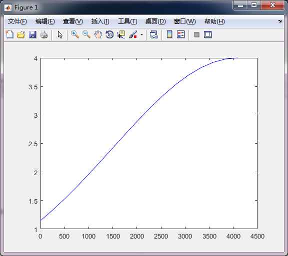
In the illustration, the abscissa represents the pixel brightness of 0~4096, and the vertical coordinate represents the gain multiple of the current brightness pixel.
DrcGain:
DrcGain confirms the maximum gain multiple, which is limited by two conditions:
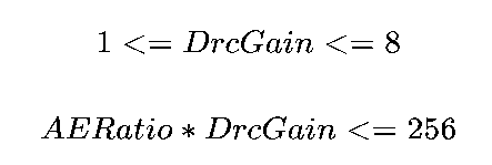
1 <= DrcGain <= 8
AERatio * DrcGain <= 256
There are the above two conditions to know that the actual DrcGain is less than 8x, during the debugging process, if DrcGain is set to 8x, but the product with AERatio is greater than 256x, the DrcGain will be clipped internally to meet the condition that the product is less than 256x.
In actual debugging, the significance of DrcGain is that at the same brightness, adding DrcGain can reduce the displacement error of long and short frames (except for sensors other than DCG mode). In view of the noise effect caused by DrcGain, since DrcGain is digital, if the sensor is still in analog gain mode, increasing DrcGain will increase the noise level; Conversely, if the sensor is in digital gain mode, there is no significant difference in increasing the DrcGain noise level.
The following figure shows the approximate curve of DrcGain when equal to 1x (red line) and 8x (blue line):
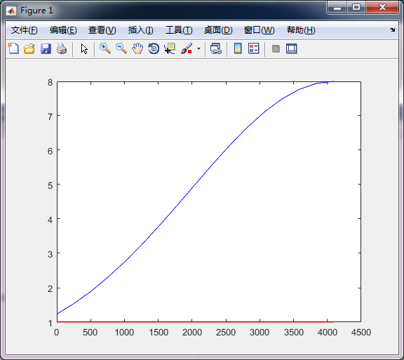
Alpha:
Alpha confirms the slope of the DrcGain curve, as shown in the figure below for the difference between 0 (red line) and 0.9 (blue line) for Alpha:
As can be seen from the figure above, when the alpha is smaller, the DrcGain curve is closer to a horizontal straight line, that is, each brightness will be magnified equally, which may introduce problems such as insufficient contrast and dark noise being amplified.
Clip:
4.3.2 4.4.3.2 HiLight debugging
【Description】
The HiLight module allows you to adjust the detail of the highlighted areas of the output RAW.
【Members】
| Member name | Description |
|---|---|
| Strength | Highlight area detail, value range [0,1] |
【Precautions】
The higher the Stength value, the better detail will be pressed in the highlights, but halos are more likely to appear at the highlight boundary. As shown in the figure below, the left figure shows when Strength is 0, and the right figure shows Strength when it is 1:
4.3.3 4.4.3.3 LocalSetting debugging
【Description】
The LocalSetting module allows you to adjust the parameters related to Local. All parameters in this module do not take effect when LocalAutoEnable=0 and LocalWeit=0, or LocalAutoEnable=1 and LocalAutoWeit=0.
4.3.3.1 4.4.3.3.1 LocalData debugging
【Description】
LocalTMOData mainly adjusts the LocalTMO weight, global contrast and dark area contrast.
【Members】
| Member name | Description |
|---|---|
| LocalWeit | Local TMO weight, value range [0,1], 0: Global TMO, 1: All Local TMO |
| LocalAutoEnable | Automatic LocalWeit switch, value range [0,1], default value is 1, accuracy 1 |
| LocalAutoWeit | Automatic LocalWeit value, value range [0,1], default value is 0.4, accuracy 0.01. |
| GlobalContrast | Global contrast, value range [0,1], default value is 0, precision 0.01. |
| LoLitContrast | Low brightness area contrast, value range [0,1], default value is 0, accuracy 0.01. |
【Precautions】
DRC is Global mode when LocalAutoEnable = 0 and LocalWeit = 0, or when LocalAutoEnable = 1 and LocalAutoWeit=0. When LocalAutoEnable=0 and LocalWeit > 0, or LocalAutoEnable=1 and LocalAutoWeit>0
GlobalContrast: The higher the value, the stronger the overall contrast (excluding dark areas). As shown in the figure below, the left figure shows when GlobalContrast is 0, and the right figure shows when GlobalContrast is 1.
LoLitContrast: The higher the value, the stronger the contrast in the dark areas. As shown in the figure below, the left figure shows when LoLitContrast is 0, and the right figure shows when LoLitContrast is 1.
4.3.4 4.4.3.4 Edge_Weit debugging
【Description】
Reduce the high-contrast edge Artifact by varying this value.
【Members】
【Precautions】
5. 4.5 Dehaze & Enhance
5.1 4.5.1 Feature description
In bad weather such as fog and haze, the quality of the collected images will be seriously reduced due to atmospheric scattering, so that the image color is grayish white, the contrast is reduced, and the object features are difficult to identify. So image dehazing technology is needed to enhance or fix to improve the visual effect.
This module consists of three modules, Dehaze, Enhance, and Hist. Dehaze is mainly used when the fog and haze are large in the picture, and the Enhanced and Hist are mostly used to enhance the contrast of the picture. Among them, Dehaze and Enhance two modules can only be opened at the same time, if two are turned on at the same time, only the Add module takes effect, and Hist can be opened together with other modules.
! [] (Resources/Dehaze Block Diagram .png)
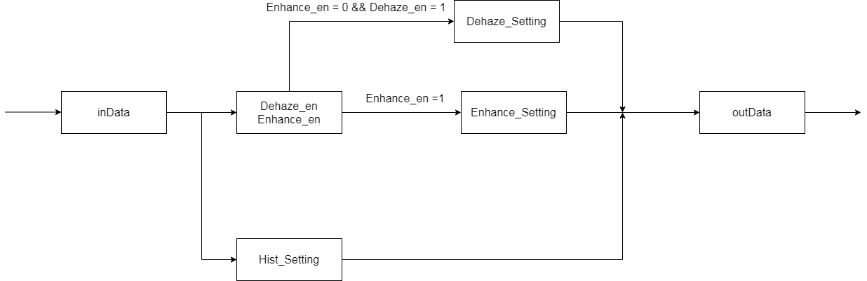
Block diagram of the Dehaze module
5.2 4.5.2 Key parameters
5.2.1 4.7.2.1 Enable
【Description】
Dehaze & Enhanced switch function
0: Off
1: Open
【Members】
【Precautions】
5.2.2 4.5.2.2 cfg_alpha
【Description】
The proportion of software configuration, the value range [0,1], the default value is 1, and the accuracy is 0.01.
0: All adaptive parameters are used
1: All use software configuration parameters, you can control the adaptive parameters and software configuration parameters according to the proportion
【Members】
【Precautions】
When the value is 0, the cfg_wt, cfg_air, cfg_tmax in Dehaze and the cfg_gratio in Hist are not valid; Conversely, when the value is 1, the Dehaze parameter is determined entirely by the cfg_wt, cfg_air, and cfg_tmax, and the Hist parameter is determined entirely by the cfg_gratio.
5.2.3 4.5.2.3 ByPassThr
【Description】
Indicates the current module threshold of bypass, with a value range of [0,1]. When the percentage difference between the current ambient brightness and the ambient brightness of the previous frame is less than ByPassThr, the parameters of this module are not updated.
【Members】
【Precautions】
During debugging with the tool, write the value to 0, otherwise debugging may be invalid.
5.2.4 4.5.2.4 Dehaze_Setting
【Description】
The dehazing parameters can be adjusted through this module.
【Members】
| Member Name | Description |
|---|---|
| en | Switch function |
| air_lc_en | Whether to use Airlight Base to make a minimum cutoff toggle |
| stab_fnum | The maximum value for frame stabilization |
| sigma | IIR-controlled sigma |
| wt_sigma | Inter-frame WT filter coefficient |
| air_sigma | Inter-frame air filter coefficient |
| tmax_sigma | Inter-frame tmax filter coefficient |
| pre_wet | Reference data IIR filter factor |
| DehazeData | dehaze debug parameter |
| Member Name | Description |
|---|---|
| EnvLv | Ambient brightness |
| EnvLv_len | EnvLv array length |
| dc_min_th | The statistical range of WT is adaptive, and the value range is [16, 120], and the default value is 64. |
| dc_min_th_len | dc_min_th array length |
| dc_max_th | WT adaptive high exposure area statistical range, the value range is [170, 255], and the default value is 192. |
| dc_max_th_len | dc_max_th array length |
| yhist_th | The statistical range of the high exposure area of the y component is [170, 255], and the default value is 249 |
| yhist_th_len | yhist_th array length |
| yblk_th | The threshold of the proportion of the number of y-component blocks, the value range is 0.002, 0.01, and the default value is 0.002. |
| yblk_th_len | yblk_th array length |
| dark_th | WT adapts to the minimum value threshold of the Y component block, the value range is [230, 250], and the default value is 250 |
| dark_th_len | dark_th array length |
| bright_min | The minimum value of the air adaptive threshold, which ranges from 160 to 200, and the default value is 180 |
| bright_min_len | bright_min array length |
| bright_max | The maximum value of the air adaptive threshold, which ranges from 210 to 250, and the default value is 240 |
| bright_max_len | bright_max array length |
| wt_max | The maximum value of WT adaptive is 0.75, 0.9, and the default value is 0.9 |
| wt_max_len | wt_max array length |
| air_min | The minimum value of air adaptation ranges from 200 to 220, and the default value is 200 |
| air_min_len | air_min array length |
| air_max | The maximum value of air adaptation ranges from 230 to 250, and the default value is 250 |
| air_max_len | air_max array length |
| tmax_base | The default value of tmax is 125, and the corresponding configuration is as follows: 200 (131), 210 (125), 220 (119), 230 (114), 240 (109), 250 (105), and 131-105 |
| Member Name | Description |
|---|---|
| tmax_base_len | tmax_base array length |
| tmax_off | tmax is an adaptive fixed value, the value range is [0.1, 0.5], and the default value is 0.1 |
| tmax_off_len | tmax_off array length |
| tmax_max | The maximum value of tmax can be 0.1, 0.5, and the default value is 0.5 |
| tmax_max_len | tmax_max array length |
| cfg_wt | The software is configured with wt, image dehazing strength, value range [0, 1], default value 0.8. |
| cfg_wt_len | cfg_wt array length |
| cfg_air | The software configures air and atmospheric light coefficient, and the value range is [0, 255], and the default value is 210 |
| cfg_air_len | cfg_air array length |
| cfg_tmax | The software is configured to tmax, the maximum value of dehazing, the value range is 0, 1, and the default value is 0.2 |
| cfg_tmax_len | cfg_tmax array length |
| bf_weight | The composite weight of the two bilateral filters can be taken in the range of [0, 1], and the default value is 0.5 |
| bf_weight_len | bf_weight array length |
| dc_weitcur | The weight of the dark channel part, the value range is [0, 1], and the default value is |
| dc_weitcur_len | dc_weitcur array length |
| range_sigma | The sigma value of the bilateral filter value range, the value range is [0, 1], and the default value is 0.4. |
| range_sigma_len | range_sigma array length |
| space_sigma_pre | When the IIR data is used as a reference, the sigma value of the double-sided filtered airspace can be in the range [0, 1], and the default value is 0.4 |
| space_sigma_pre_len | space_sigma_pre array length |
| space_sigma_cur | When the current data is used as a reference, the sigma value of the bilateral filtered airspace can be in the range [0, 1], and the default value is 0.8 |
| space_sigma_cur_len | space_sigma_cur array length |
【Precautions】
stab_fnum: The parameter of dehaze is to gradually reach a stable value from 0, sw_dhaze_stab_fnum is the number of frames specified by the software to reach stability, generally 10 frames is more appropriate, the maximum value of this parameter can be allocated to 31, and the time of up to 1s will enter a stable state;
5.2.5 4.5.2.5 Enhance_Setting
【Description】
This module allows you to adjust the image contrast.
【Members】
| Member Name | Description |
|---|---|
| en | enhance function switch |
| enhance_curve | Low Frequency Curve |
| EnhanceData | enhance debug parameter |
| Member Name | Description |
|---|---|
| EnvLv | Ambient brightness |
| EnvLv_len | Ambient brightness array length |
| enhance_value | Universal contrast dynamics, value range [0, 16], recommended range [1, 2] |
| enhance_value_len | enhance_value array length |
| enhance_chroma | Enhancement adjustment parameters of chromaticity, value range [0, 16], recommended range [1, 2] |
| enhance_chroma_len | enhance_chroma array length |
【Precautions】
enhance_value: The larger the contrast
enhance_chroma: The larger the saturation, the higher the saturation
5.2.6 4.5.2.6 Hist_Setting
【Description】
This module adjusts the image contrast, which is usually used when the contrast is not enough after dehazing.
【Members】
| Member Name | Description |
|---|---|
| en | Hist function switch |
| hist_para_en | Histogram stretch control switch |
| HistData | hist debug parameter |
| Member Name |
Description |
|---|---|
| EnvLv | Ambient brightness |
| EnvLv_len | EnvLv array length |
| hist_gratio | Histogram stretch multiple, histogram equalization control coefficient, value range [0, 32] |
| hist_gratio_len | hist_gratio array length |
| hist_th_off | The statistical threshold of the histogram ranges from 0 to 255, and the default value is 64 |
| hist_th_off_len | hist_th_off array length |
| hist_k | The adaptive threshold magnification of the histogram ranges from 0 to 7, and the default value is 2 |
| hist_k_len | hist_k array length |
| hist_min | The minimum value of the statistical threshold of the histogram, the value range is [0,2], and the default value is 0.016 |
| hist_min_len | hist_min array length |
| hist_scale | Histogram equalization control coefficient, value range [0, 32] |
| hist_scale_len | hist_scale array length |
| cfg_gratio | The software configures the histogram stretch multiplier and the histogram equalization control coefficient, and the value range is [0, 32) |
| cfg_gratio_len | cfg_gratio array length |
【Precautions】
hist_para_en: When the value is 1, the hist_scale takes effect, but the hist_gratio does not take effect; Conversely, when the value is 0, the hist_scale does not take effect, hist_gratio takes effect.
hist_gratio: The higher the value, the more the histogram is stretched and the overall brightness of the image is higher.
hist_th_off: The higher the value, the larger the statistical value of the histogram and the higher the overall brightness of the image.
hist_k: The higher the value, the larger the statistical value of the histogram and the higher the overall brightness of the image.
hist_min: The larger the value, the larger the statistical value of the histogram and the higher the overall brightness of the image.
5.3 4.5.3 Debugging steps
Dehaze debugging mainly includes three parts: Dehaze, Enhanced and Hist debugging.
5.3.1 4.5.3.1 Dehaze debugging
【Description】
The defogging intensity is recommended to be adjusted by the following three parameters. The following three parameters vary according to ISO. During the adjustment process, the cfg_alpha needs to be set to 1.
【Members】
| Member name | Description |
|---|---|
| cfg_wt | Software configuration wt, image dehazing force |
| cfg_air | Software configuration air, atmospheric light curtain coefficient |
| cfg_tmax | Software configuration tmax, maximum dehazing |
【Precautions】
1.cfg_wt: The larger the value, the greater the dehazing force, it should be noted that wt is best not to exceed 0.9, in most cases wt more than 0.9 will appear unnatural processing effect, unless the fog in the scene is very large. (As shown in the figure below, from left to right, Dehaze_en= 0, Dehaze_en = 1 and cfg_wt= 0.4, Dehaze_en = 1 and cfg_wt= 0.8)
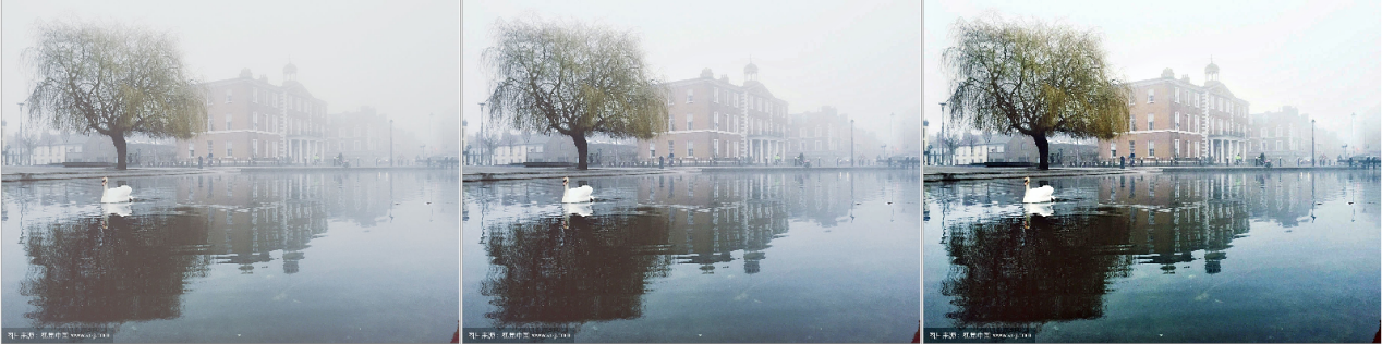
cfg_wt comparison chart
2.cfg_air: It can also control the dehazing intensity, and at the same time affect the dehazing effect of the overexposed area of the image, which is used with sw_dhaz_cfg_wt.
As can be seen as shown in the figure below, for the following input image, the more natural the dehazing effect at the junction of the larger the sky in the cfg_air, the more natural the defogging effect when the cfg_air is 250, there will be no intermediate layering problem, the debugging of AIR mainly considers whether there is a sky and overexposure area in the image, if there is a need to increase AIR, to avoid the problem of layering or loss of details. (As shown in the figure below, from left to right, Dehaze_en= 0, Dehaze_en= 1 and cfg_air= 200, Dehaze_en= 1 and cfg_air= 250)
cfg_air comparison chart
3.cfg_tmax: The smaller the value, the greater the dehazing force in the depth of field direction, and the larger the value, the smaller the dehazing force in the depth of field direction.
As can be seen as shown in the figure below, when the cfg_tmax is 0.1, the fog in the depth of field direction is removed relatively cleanly, some details can already be seen, and when the cfg_tmax is 0.5, it is much weaker, the fog in the depth of field direction is not removed as much as possible, removing too much will destroy the layering of the image, usually 0.2 is a more suitable value. (As shown in the figure below, from left to right, Dehaze_en= 0, Dehaze_en= 1 and cfg_tmax= 0.1, Dehaze_en= 1 and cfg_tmax= 0.5)
cfg_tmax comparison chart
5.3.2 4.5.3.2 Enhanced debugging
【Description】
Universal Contrast Enhancement is adjusted by enhance_value. enhance_value varies according to ISO.
【Members】
| Member name | Description |
|---|---|
| enhance_value | General contrast force |
| enhance_chroma | Enhanced adjustment parameters for chromaticity |
| enh_curve | Low frequency curve |
【Precautions】
1.enhance_value: The larger the value, the stronger the contrast. (As shown in the figure below, from left to right, Enhance_en = 0, Enhance_en = 1 and enhance_value = 1.5)
enhance_value comparison chart
2.enhance_chroma: The larger the saturation, the higher the saturation (as shown in the figure below, from left to right, Enhance_en = 0, Enhance_en = 1 and enhance_chroma = 1.5)

enhance_chroma comparison chart
3.enh_curve:Dark area brightness and contrast can be improved by lowering the dark area parameter.
5.3.3 4.5.3.3 Hist debugging
【Description】
Histogram equalization Hist recommends adjusting by the following two parameters. The following two parameters vary according to ISO. During the adjustment process, the cfg_alpha needs to be set to 1.
【Members】
| Member name |
Description |
|---|---|
| cfg_gratio | Software configuration histogram stretch multiplier, histogram equalization control factor |
【Precautions】
cfg_gratio: Related to WT, the larger WT Gratio, the larger the GT, the smaller the GRATIO, the smaller the GT. The parameters are too large to make the effect look unnatural, the overall color is blue, and some other details will be lost again, gratio is a coefficient of histogram stretching, its size is related to wt, the larger wt gratio needs to be appropriately adjusted, the smaller wt gratio, to avoid wt is smaller but configured with a relatively large gratio. (As shown in the figure below, from left to right, Hist_en = 0, Hist_en = 1 and cfg_gratio = 0.768, Hist_en = 1 and cfg_gratio= 2)
cfg_gratio comparison chart
6. 4.6 DPCC
6.1 4.6.1 Description of the feature
The DPCC module includes ISP DPCC and Sensor DPCC.
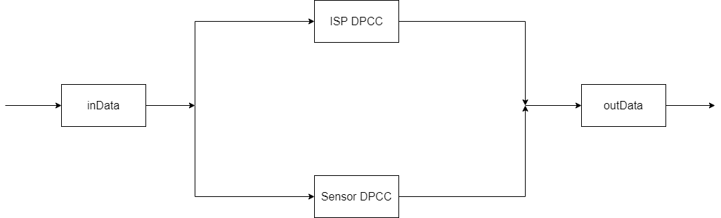
6.1.1 4.6.1.1 ISP DPCC
The ISP DPCC hardware module provides six dead pixel determination algorithms, namely RK, LC, PG, RND, RG, and RO to detect dead pixels, and remove dead pixels after detection. Each decision algorithm has independent switching and threshold parameter adjustment. The six dead pixel determination algorithms can detect bright spots, dark spots and dynamic dead pixels, and the detection capabilities are different for different dead pixels. RO and PG are more effective for two kinds of dead pixels of single bright spots and dark spots, and RK, RG and RND are more effective for multiple dead pixels.
Support six dead pixel determination algorithms, select several algorithm enablement, and combine into a dead pixel determination scheme. When all the dead pixel determination algorithms enabled by the scheme are judged to be dead pixels, the point is determined to be dead pixels by the scheme. For example, if the four algorithms RK, LC, PG, RND can be used, the conditions of the four algorithms must be met to determine that the point to be measured is a dead value. The following is a dead pixel determination scheme that enables six dead pixel determination algorithms.
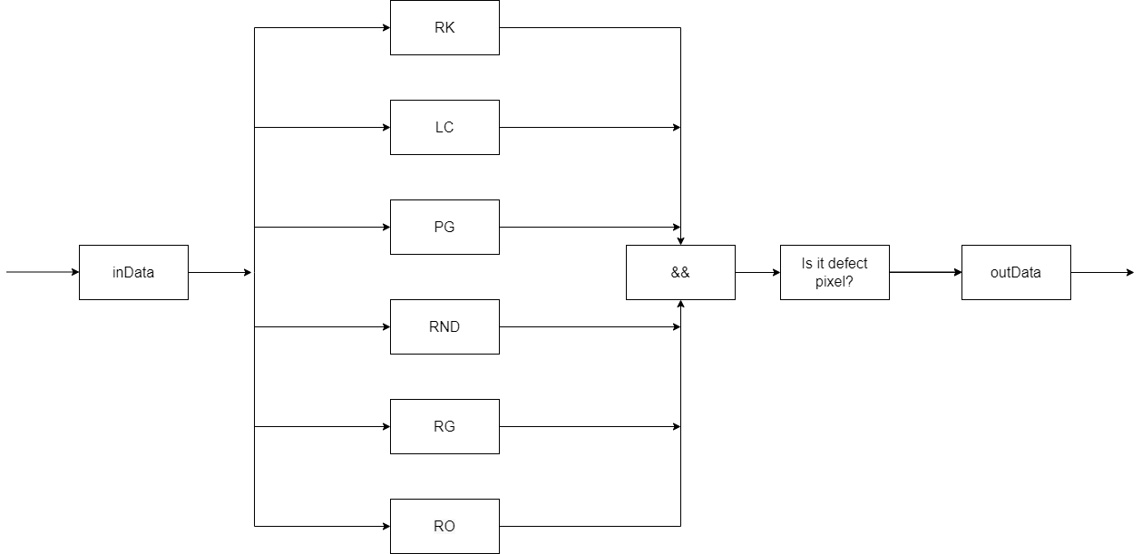
The ISP DPCC module supports up to three configurable dead pixel determination schemes (Set1~3) and one dead pixel decision scheme (fix_set) that only supports the combination of fixed dead pixel determination algorithm enabled by the switch, for a total of four decision schemes. As long as the pixel to be measured is judged as a dead pixel by any enabled dead pixel determination scheme, it is judged as a dead pixel by the DPCC module and performs a dead pixel compensation action.
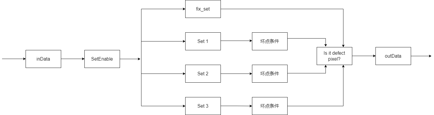
6.1.1.1 4.6.1.1.1 Expert_mode
In Expert_mode mode, users can directly configure ISP DPCC hardware, which mainly includes four dead pixel determination schemes: fix_set, set1, set2, and set3.
6.1.1.2 4.6.1.1.2 Fast_mode
Fast_mode mode is a working mode for dead pixel type differentiation organized by RK based on the ability abstraction of each dead pixel determination algorithm of ISP DPCC hardware module, which mainly includes the following methods:
Single_level: For the mode that is more effective for a single isolated dead pixel, only the dead pixel determination scheme Set1 is enabled, which enables six dead pixel determination algorithms, and as the level increases, the number of algorithms used decreases, the threshold changes, and the ability to remove dead pixels is stronger;
Double_level: A pattern that is valid for two adjacent dead pixels, such as a 1x2, 2x1 dead pixel cluster. Among them, only the dead pixel determination scheme Set2 is enabled, which enables four dead pixel determination algorithms such as RK, LC, PG, RND, RO and with the increase of the level, the threshold changes and the ability to remove dead pixels is stronger;
Triple_leve: Dead pixel clusters for three or more pixels within a neighborhood are more effective. Among them, the dead pixel determination scheme Set3 and fix_set are enabled, in which set3 uses RK, PG, RND, RO four dead pixel determination algorithms, with the increase of the level, the threshold changes and the ability to remove dead pixels is stronger.
Since the above three modes are not duplicated in the hardware dead pixel determination scheme, they are allowed to be enabled at the same time, but the Triple_level will increase the strength of the Double_level and Single_level, and the Double_level will enhance the strength of the Single_level.
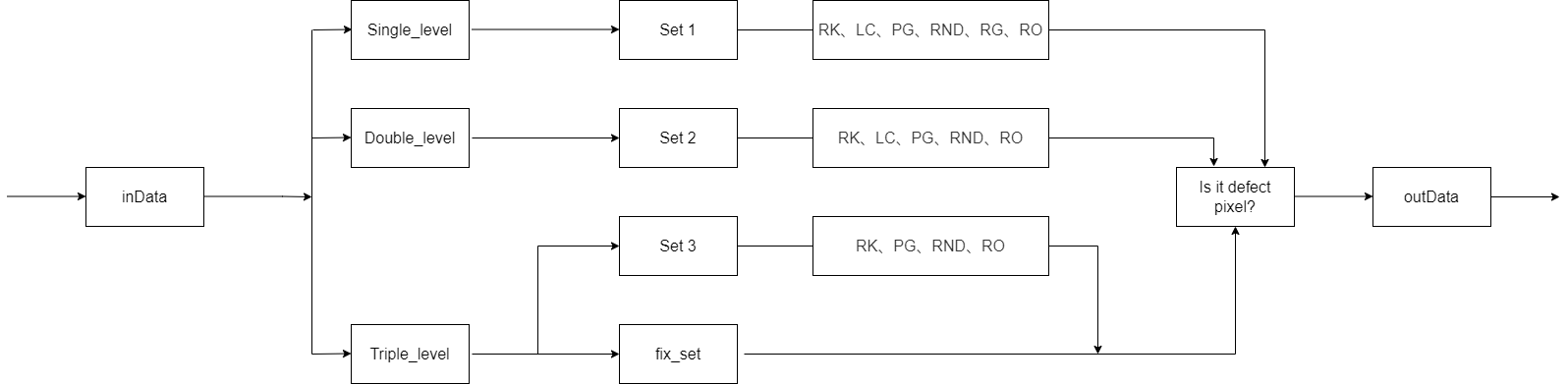
6.1.2 4.6.1.2 Sensor DPCC
Sensor DPCC is the DPCC function that comes with the sensor side, and in the case of sensor driver implementation support, AIQ supports controlling the Sensor side DPCC module through the parameters under the module in the JSON parameter file.
6.2 4.6.2 Key parameters
6.2.1 4.6.2.1 Enable
【Description】
DPCC switch function
0: Off
1: Open
【Members】
【Precautions】
6.2.2 4.6.2.2 Fast_mode
【Description】
Use this section to adjust the relevant parameters of the Fast_mode.
【Members】
| Member name | Description |
|---|---|
| Fast_mode_enable | Fast_mode switch function, 0: off, 1: on |
| ISO | Environmental ISO |
| Single_enable | Single dead pixel removal switch, 0: off, 1: on |
| Single_level | Single dead pixel removal force, value range [0, 10] |
| Double_enable | Double dead pixel removal switch, 0: off, 1: on |
| Double_level | Double dead pixel removal force, value range [0, 10] |
| Triple_enable | Multi-dead pixel removal switch, 0: off, 1: on |
| Triple_level | Multiple dead pixel removal force, value range [0, 10] |
【Precautions】
Fast_mode_enable: When the value is 0, the Fast_mode is turned off and the Expert_mode is turned on; Conversely, when the value is 1, the Fast_mode is turned on and Expert_mode off.
Double dead pixels and multiple dead pixels refer to multiple dead pixels in each other.
Dead pixel removal force, 0 means no treatment, 1~10 represents different intensity dead pixel removal force, the greater the value, the greater the force.
If you do not use the Fast_mode to achieve the desired pressure, use Expert_mode.
6.2.3 4.6.2.3 Expert_mode
【Description】
Use this section to adjust the relevant parameters of the Expert_mode.
【Members】
| Member name | Description |
|---|---|
| stage1_Enable | Default value 1 |
| grayscale_mode | Black and white mode switch, 0: off, 1: on |
| rk_out_sel | The use of ro_lim in the RK dead pixel algorithm, 0:ro_lim1,1:ro_lim2,2:ro_lim3 |
| dpcc_out_sel | Dead pixel correction mode, 0: median mode, 1: RK mode |
| stage1_rb_3x3 | Default value: 0 |
| stage1_g_3x3 | Default value: 0 |
| stage1_inc_rb_center | When the red/blue channel is removed for dead pixels with the median mode, whether to include the point to be removed, 0:No, 1:Yes, the default value is 1 |
| stage1_inc_g_center | When the green channel removes dead pixels with the median mode, whether to include the points to be removed, 0:No, 1:Yes, the default value is 1 |
| set | Scenario conditions |
【Precautions】
grayscale_mode: When the sensor is colored, set to 0; Conversely, when the sensor is black and white, it is set to 1.
6.2.3.1 4.6.2.3.1 SetEnable
【Description】
Four scheme switches in the Expert_mode.
【Members】
| Member name | Description |
|---|---|
| ISO | Environmental ISO |
| stage1_use_fix_set | Built-in dead pixel condition switch, 0: off, 1: on |
| stage1_use_set3 | The third dead pixel judgment condition switch in the set_cell, 0: off, 1: open |
| stage1_use_set2 | The second dead pixel judgment condition switch in the set_cell, 0: off, 1: on |
| stage1_use_set1 | The first dead pixel judgment condition switch in the set_cell, 0: off, 1: on |
【Precautions】
6.2.3.2 4.6.2.3.2 set
【Description】
Through this part, the threshold of dead pixel conditions can be adjusted, mainly including six judgment conditions of RK, LC, PG, RND, RG and RO, and the relationship between the six conditions is and.
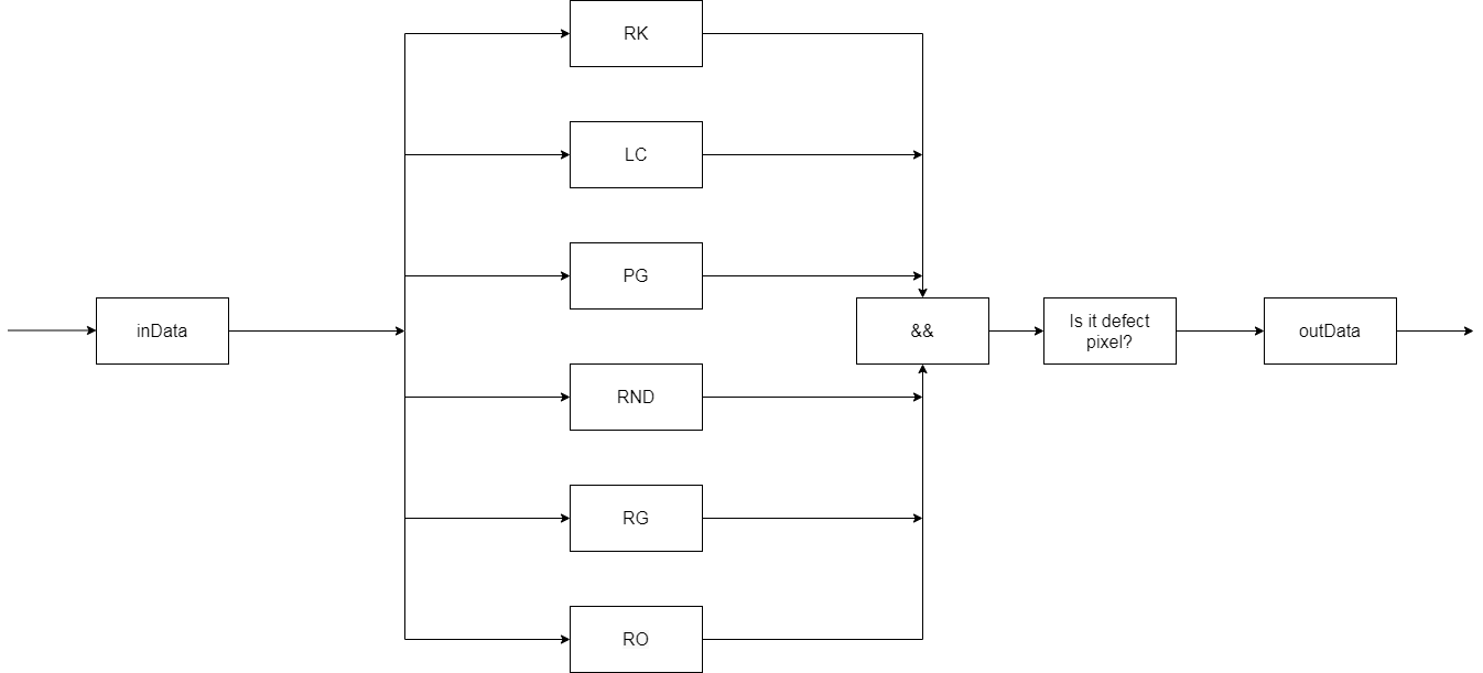
set_cell block diagram
【Members】
| Member name | Description |
|---|---|
| RK | RK dead pixel determination algorithm |
| LC | LC dead pixel determination algorithm |
| PG | PG dead pixel determination algorithm |
| RNG | RND dead pixel determination algorithm |
| RG | RG dead pixel determination algorithm |
| RO | RO dead pixel determination algorithm |
【Precautions】
6.2.3.2.1 4.6.2.3.2.1 RK
【Description】
This section allows you to adjust the parameters related to the RK algorithm in the dead pixel detection algorithm.
【Members】
| Member name | Description |
|---|---|
| RK_red_blue_enable | RK dead pixel determination algorithm red/blue channel switch, 0: off, 1: on |
| RK_green_enable | RK dead pixel determination algorithm green channel switch, 0: off, 1: on |
| rb_sw_mindis | RK dead pixel determination algorithm red/blue channel threshold 1, value range [0,255] |
| g_sw_mindis | The green channel threshold of the RK dead pixel determination algorithm is 1, and the value range is [0,255] |
| sw_dis_scale_min | RK dead pixel determination algorithm threshold 2, value range [0,63] |
| sw_dis_scale_max | RK dead pixel determination algorithm threshold 3, value range [0,63] |
【Precautions】
6.2.3.2.2 4.6.2.3.2.2 LC
【Description】
This section allows you to adjust the LC algorithm parameters in the dead pixel detection algorithm.
【Members】
| Member name | Description |
|---|---|
| LC_red_blue_enable | LC dead pixel determination algorithm red/blue channel switch, 0: off, 1: on |
| LC_green_enable | LC dead pixel determination algorithm green channel switch, 0: off, 1: on |
| rb_line_thr | LC dead pixel determination algorithm red/blue channel threshold, value range [0,255], default value 16 |
| g_line_thr | LC dead pixel determination algorithm green channel threshold, value range [0,255], default value 12 |
| rb_line_mad_fac | LC dead pixel determination algorithm red/blue channel coefficient, value range [0,63], default value 34 |
| g_line_mad_fac | The green channel coefficient of LC dead pixel determination algorithm, value range [0,63], default value 16 |
【Precautions】
6.2.3.2.3 4.6.2.3.2.3 PG
【Description】
This section allows you to adjust the PG algorithm parameters in the dead pixel detection algorithm.
【Members】
| Member name | Description |
|---|---|
| PG_red_blue_enable | PG dead pixel determination algorithm red/blue channel switch, 0: off, 1: on |
| PG_green_enable | PG dead pixel determination algorithm green channel switch, 0: off, 1: on |
| rb_pg_fac | PG dead pixel determination algorithm red/blue channel coefficient, value range [0,63], default value 4 |
| g_pg_fac | PG dead pixel determination algorithm green channel coefficient, value range [0,63], default value 3 |
【Precautions】
6.2.3.2.4 4.6.2.3.2.4 RND
【Description】
This section allows you to adjust the parameters related to the RND algorithm in the dead pixel detection algorithm.
【Members】
| Member name | Description |
|---|---|
| RND_red_blue_enable | RND dead pixel determination algorithm red/blue channel switch, 0: off, 1: on |
| RND_green_enable | RND dead pixel determination algorithm green channel switch, 0: off, 1: on |
| rb_rnd_thr | RND dead pixel determination algorithm red/blue channel threshold, value range [0,255], default value 8 |
| g_rnd_thr | The green channel threshold of the RND dead pixel determination algorithm, the value range is [0,255], and the default value is 8 |
| rb_rnd_offs | RND dead pixel determination algorithm red/blue channel offset value, value range [0,3], default value 3 |
| g_rnd_offs | The green channel offset value of the RND dead pixel determination algorithm, the value range is [0,3], and the default value is 3 |
【Precautions】
6.2.3.2.5 4.6.2.3.2.5 RG
【Description】
This section allows you to adjust the parameters of the RG algorithm in the dead pixel detection algorithm.
【Members】
| Member name | Description |
|---|---|
| RG_red_blue_enable | RG dead pixel determination algorithm red/blue channel switch, 0: off, 1: on |
| RG_green_enable | RG dead pixel determination algorithm green channel switch, 0: off, 1: on |
| rb_rg_fac | RG dead pixel determination algorithm red/blue channel coefficient, value range [0,63], default value 8 |
| g_rg_fac | The green channel coefficient of RG dead pixel determination algorithm, the value range [0,63], the default value is 8 |
【Precautions】
6.2.3.2.6 4.6.2.3.2.6 RO
【Description】
This section allows you to adjust the parameters related to the RO algorithm in the dead pixel detection algorithm.
【Members】
| Member name | Description |
|---|---|
| RO_red_blue_enable | RO dead pixel determination algorithm red/blue channel switch, 0: off, 1: on |
| RO_green_enable | RO dead pixel determination algorithm green channel switch, 0: off, 1: on |
| rb_ro_lim | RO dead pixel determination algorithm red/blue channel threshold, value range [0,3], default value 1 |
| g_ro_lim | RO dead pixel determination algorithm green channel threshold, value range [0,3], default value 1 |
【Precautions】
6.2.4 4.6.2.5 sensor_dpcc
【Description】
This section allows you to adjust the dead pixel removal force of the sensor itself.
【Members】
| Member name | Description |
|---|---|
| sensor_dpcc_auto_en | Sensor DPCC switch function, 0: off, 1: on |
| max_level | Maximum force to remove dead pixels |
| ISO | Environmental ISO |
| level_single | Remove individual dead pixel force |
| level_multiple | Remove multiple dead pixel forces |
【Precautions】
6.3 4.6.3 Debugging steps
DPCC debugging mainly includes three parts: Fast_mode, Expert_mode and sensor_dpcc debugging. Fast_mode and Expert_mode are mutually exclusive, determined by the Fast_mode_enable in the Fast_mode, when the Fast_mode_enable value is 0, the Fast_mode is closed and the Expert_mode is on; Conversely, when the Fast_mode_enable value is 1, the Fast_mode is turned on and Expert_mode closed.
In the actual debugging process, it is recommended to use the Fast_mode to remove dead pixels first, and if the Fast_mode cannot achieve the desired dead pixel removal force, then use Expert_mode.
6.3.1 4.6.3.1 Fast_mode debugging
【Description】
In Fast_mode, single dead pixels are mainly removed by Single_level, two adjacent dead pixels Double_level removed, and more than three adjacent dead pixels Triple_level removed.
The three functions do not affect each other, but Triple_level will increase the force of the Double_level, and the Double_level will increase the strength of the Single_level.
【Members】
| Member name | Description |
|---|---|
| Fast_mode_enable | Fast_mode switch function, 0: off, 1: on |
| Single_level | Single dead pixel removal force, value range [0, 10] |
| Double_level | Double dead pixel removal force, value range [0, 10] |
| Triple_level | Multiple dead pixel removal force, value range [0, 10] |
【Precautions】
Dead pixel removal force, 0 means no treatment, 1~10 represents different intensity dead pixel removal force, the greater the value, the greater the force.
When a certain dead pixel mode is turned on, the corresponding dead pixel removal force cannot be 0. For example, when the Single_enable is turned on, the value in the Single_level cannot be 0.
6.3.2 4.6.3.2 Expert_mode debugging
【Description】
The Expert_mode is mainly removed by stage1_use_fix_set, stage1_use_set1, stage1_use_set2, stage1_use_set3 and set_cell dead pixels,
Among them, stage1_use_fix_set, stage1_use_set1, stage1_use_set2 and stage1_use_set3 are four methods to detect dead pixels, and the four methods do not affect each other, that is, if all four methods are enabled, as long as any of them detect a point as a dead pixel, the point is a dead pixel.
The conditions of the stage1_use_fix_set detection method are fixed in hardware, and the conditions of the three methods of stage1_use_set1, stage1_use_set2 and stage1_use_set3 correspond to cell1, cell2 and cell3 in the set_cell, respectively.
The set_cell contains six dead pixel determination algorithms of RK, LC, PG, RND, RG and RO, and the relationship between the six algorithms is “and”, that is, if the six judgment conditions are enabled, the point to be measured needs to meet six conditions to be judged as a dead pixel.
【Members】
| Member name | Description |
|---|---|
| stage1_use_fix_set | Built-in dead pixel condition switch, 0: off, 1: on |
| stage1_use_set1 | The first dead pixel judgment condition switch in the set_cell, 0: off, 1: on |
| stage1_use_set3 | The third dead pixel judgment condition switch in the set_cell, 0: off, 1: open |
| set_cell | Dead pixel judgment condition |
【Precautions】
The six algorithms of RK, LC, PG, RND, RG and RO are divided into green, red and blue channels to judge the dead pixels, and it is recommended that the two channels be turned on and off synchronously.
The six algorithms can be turned on and off independently, and because the relationship between the six algorithms is “and”, the more algorithms are turned on, the less likely it is to determine that it is a dead pixel. However, due to the presence of noise, when the algorithm is turned on less, there may be “edge jitter” in the picture, that is, wavy lines appear on fixed edges in the picture, and there is a difference between frames. Therefore, in actual use, it is recommended that at least three algorithms be enabled under each set.
6.3.2.1 4.6.3.2.1 RK
【Description】
This section allows you to adjust the parameters related to the RK algorithm in the dead pixel detection algorithm.
【Members】
| Member name | Description |
|---|---|
| enable | RK dead pixel determination algorithm switch, 0: off, 1: on |
| ro_lim | RK dead pixel determination algorithm offset value, value range [0,3] |
| sw_mindis | RK dead pixel determination algorithm threshold 1, value range [0,255] |
| sw_dis_scale_min | RK dead pixel determination algorithm threshold 2, value range [0,63] |
| sw_dis_scale_max | RK dead pixel determination algorithm threshold 3, value range [0,63] |
【Precautions】
ro_lim: The larger the value, the easier it is to judge as a dead pixel.
sw_mindis: The smaller the value, the easier it is to judge as a dead pixel.
sw_dis_scale_max: The smaller the value, the easier it is to judge as a dead pixel.
sw_dis_scale_max : The smaller the value, the easier it is to judge as a dead pixel.
6.3.2.2 4.6.3.2.2 LC
【Description】
This section allows you to adjust the LC algorithm parameters in the dead pixel detection algorithm.
【Members】
| Member name |
Description |
|---|---|
| enable | LC dead pixel determination algorithm switch, 0: off, 1: on |
| line_thr | LC dead pixel determination algorithm channel threshold, value range [0,255], default value 12 |
| line_mad_fac | LC dead pixel determination algorithm channel coefficient, value range [0,63], default value 16 |
【Precautions】
line_thr: The smaller the value, the easier it is to judge as a dead pixel.
line_mad_fac: The smaller the value, the easier it is to judge as a dead pixel.
6.3.2.3 4.6.3.2.3 PG
【Description】
This section allows you to adjust the PG algorithm parameters in the dead pixel detection algorithm.
【Members】
| Member name |
Description |
|---|---|
| enable | PG dead pixel determination algorithm switch, 0: off, 1: on |
| pg_fac | PG dead pixel determination algorithm channel coefficient, value range [0,63], default value 3 |
【Precautions】
pg_fac: The smaller the value, the easier it is to judge as a dead pixel.
6.3.2.4 4.6.3.2.4 RND
【Description】
This section allows you to adjust the parameters related to the RND algorithm in the dead pixel detection algorithm.
【Members】
| Member name |
Description |
|---|---|
| enable | RND dead pixel determination algorithm switch, 0: off, 1: on |
| rnd_thr | RND dead pixel determination algorithm channel threshold, value range [0,255], default value 8 |
| rnd_offs | RND dead pixel determination algorithm channel offset value, value range [0,3], default value 3 |
【Precautions】
rnd_thr: The smaller the value, the easier it is to judge as a dead pixel.
rnd_offs: The smaller the value, the easier it is to judge as a dead pixel.
6.3.2.5 4.6.3.2.5 RG
【Description】
This section allows you to adjust the parameters of the RG algorithm in the dead pixel detection algorithm.
【Members】
| Member name |
Description |
|---|---|
| enable | RG dead pixel determination algorithm switch, 0: off, 1: on |
| rg_fac | RG dead pixel determination algorithm channel coefficient, value range [0,63], default value 8 |
【Precautions】
rg_fac: The smaller the value, the easier it is to judge as a dead pixel.
6.3.2.6 4.6.3.2.6 RO
【Description】
This section allows you to adjust the parameters related to the RO algorithm in the dead pixel detection algorithm.
【Members】
| Member name |
Description |
|---|---|
| enable | RO dead pixel determination algorithm channel switch, 0: off, 1: on |
| ro_lim | RO dead pixel determination algorithm channel threshold, value range [0,3], default value 1 |
【Precautions】
ro_lim: The larger the value, the easier it is to judge as a dead pixel.
6.3.3 4.6.3.3 sensor_dpcc debugging
【Description】
sensor_dpcc mainly controls the dead pixel removal function on the sensor side through max_level, level_single, and level_multiple. This function requires the sensor itself to have the function of removing dead pixels, and the driver configuration is completed before it can be used.
【Members】
| Member name | Description |
|---|---|
| max_level | Maximum force to remove dead pixels |
| level_single | Remove individual dead pixel force |
| level_multiple | Remove multiple dead pixel forces |
【Precautions】
max_level: Define the maximum value of the dead pixel removal force at the sensor end, mainly to subdivide a single level of dead pixel removal force.
The intensity of level_single and level_multiple cannot exceed max_level.
7. 4.7 Gamma
7.1 4.7.1 Feature description
The Gamma curves are adjusted with this module, including three Gamma curves, curve_normal, curve_hdr and curve_night.
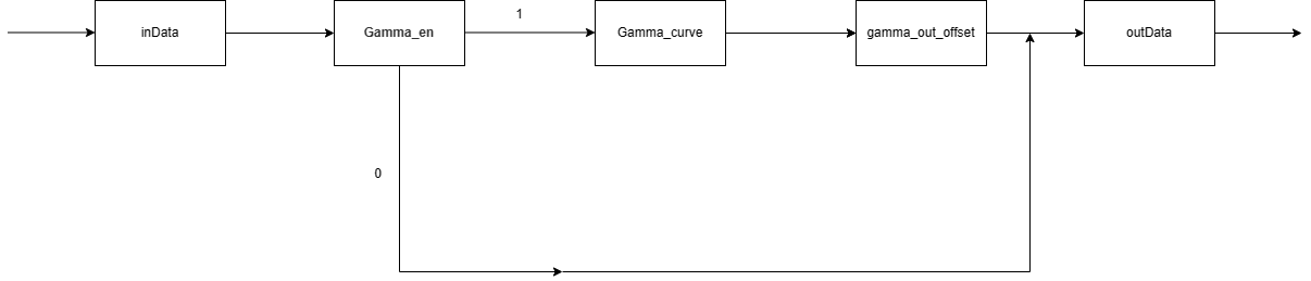
GAMMA block diagram
7.2 4.7.2 Key parameters
7.2.1 4.7.2.1 Gamma_en
【Description】
Gamma switch function
0: Off
1: Open
【Members】
【Precautions】
7.2.2 4.7.2.2 Gamma_out_offset
【Description】
Gamma curve correction function, value range [-2048, 2048], default value 0.
【Members】
【Precautions】
The final gamma curve used is, Gamma_curve-Gamma_out_offset.
7.2.3 4.7.2.3 Gamma_curve
【Description】
49-point Gamma curve Y-axis value, value range [0,4095].
【Members】
【Precautions】
The Gamma curve X-axis point is fixed at 49 points, i.e
  int X_isp30[49] = { 0, 1, 2, 3, 4, 5, 6, 7, 8, 10, 12, 14, 16, 20, 24, 28, 32,
  40, 48, 56, 64, 80, 96, 112, 128, 160, 192, 224, 256, 320, 384, 448, 512, 640,
  768, 896, 1024, 1280, 1536, 1792, 2048, 2304, 2560, 2816, 3072, 3328, 3584, 3840,
  4095};
7.3 4.7.3 Debugging steps
8. 4.8 Debayer
8.1 4.8.1 Feature description
Since most color cameras use a single sensor to obtain image information, and each sensor surface is covered with a CFA (Color Filter Array), so that each pixel can only obtain one of the three primary colors of R, G, and B. Since only one color component per pixel of the color filter array is known, in order to obtain a color image, the other two missing color components need to be interpolated using the known color information, a process known as demosaic (Debayer or Demosaic). The module supports four pattern modes: RGGB, BGGR, GRBG, and gbrg, and does not support RGBIR mode.
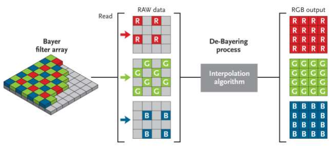
Fig. 4-10-1 Schematic diagram of Debayer function
8.2 4.8.2 Key parameters
8.2.1 Enable
【Description】
Debayer module enable bit, 0: off, 1: on.
8.2.2 debayer_filter1
【Description】
Low-frequency gradient filter, value range [-8,7].
8.2.3 debayer_filter2
【Description】
High-frequency gradient filter, value range [-8,7].
8.2.4 debayer_gain_offset
【Description】
The offset value of the gradient when sharpening the weight in the G channel interpolation coefficient is calculated, and the value range is [0,15].
8.2.5 ISO
【Description】
The ISO value of the current file, the value range is [50,2048].
8.2.6 sharp_strength
【Description】
The maximum value of the G-channel interpolation sharpening weight is in the range of [0,4].
8.2.7 debayer_hf_offset
【Description】
The offset value when calculating the gradient is ranged from [0,4095].
8.2.8 debayer_offset
【Description】
The offset of the G channel clip can be in the range of [0,15]. The higher the value, the larger the clip range.
8.2.9 debayer_clip_en
【Description】
G-channel interpolation clip switch, 0: off, 1: on.
8.2.10 debayer_filter_g_en
【Description】
G-channel interpolation result filter switch, 0: off, 1: on.
8.2.11 debayer_filter_c_en
【Description】
Chromatic aberration filter switch, 0: off, 1: on.
8.2.12 debayer_thed0
【Description】
The higher the value, the smaller the probability of selecting the high-frequency weight, and the value range is [0,16].
8.2.13 debayer_thed1
【Description】
The higher the value, the smaller the probability of selecting the low-frequency weight, and the value range is [0,16].
8.2.14 debayer_dist_scale
【Description】
The higher the value, the smaller the probability of selecting the high-frequency weight, and the value range is [0,16].debayer_hf_offset
8.2.15 debayer_cnr_strength
【Description】
The intensity of the clip during chromatic aberration filtering, the value range is [0,9].
8.2.16 debayer_shift_num
【Description】
The smaller the value, the larger the range of the chromatic aberration clip, which can be taken in the range of [0,4].
8.3 4.8.3 Explanation of terms
| Abbreviation | Description |
|---|---|
| CFA | Color Filter Array |
| Go Mosaic | Debayer or Demosaic, the process of converting a single-pixel monochrome Bayer RGB to a three-color RGB |
| Filter | A set of filtering parameters to remove unwanted signals from the digital image |
| Chromatic aberration map |
The interpolated G-channel image is inferior to the original raw image |
9. 4.10 GIC
9.1 4.10.1 Description of the feature
This module allows the GIC parameters to be adjusted. The main parameters of GIC are divided into two parts: GIC related parameters and noise-related parameters in the GIC_ISO, in which the noise-related parameters are obtained by calibration, and the GIC related parameters can adjust the GIC strength.
9.2 4.10.2 Key parameters
9.2.1 4.10.2.1 enable
【Description】
GIC switch function
0: Off
1: Open
【Members】
【Precautions】
9.2.2 4.10.2.3 gr_ration
【Description】
Determine the gr and GB compensation value parameters, the value range [0,3], and the default value is 0.
【Members】
【Precautions】
9.2.3 4.10.2.5 SettingV21
【Description】
Interpolate the relevant parameters according to the ISO.
【Members】
| Member name | Description |
|---|---|
| iso | Environmental iso |
| min_busy_thre | Busy area detection capability, value range [0, 1023], default value 160 |
| min_grad_thr1 | The number threshold of non-edge areas is 1, the GIC intensity control value, the value range [0, 1023], and the default value is 32 |
| min_grad_thr2 | The number threshold of non-edge areas is 2, the GIC intensity control value, the value range [0, 1023], and the default value is 32 |
| k_grad1 | The response threshold of the edge (horizontal and vertical gradient) is 1, the value range is [0, 15], and the default value is 5 |
| k_grad2 | The response threshold of the edge (horizontal and vertical gradient) is 2, the value range is [0, 15], and the default value is 1 |
| gb_thre | Scale factor for scale, value range [0, 15], default value 7 |
| maxCorV | Limit the maximum compensation value of GB in the edge area, the value range is [0, 1023], and the default value is 40 |
| maxCorVboth | Limit the maximum compensation value of GB in flat (non-edge) areas, the value range is [0, 1023], and the default value is 8 |
| dark_thre | Define the threshold value of the dark area 1, the value range [0, 2047], the default value 120 |
| dark_threHi | Define the threshold value of the dark area 2, the value range [0, 2047], the default value is 240 |
| k_grad1_dark | The threshold value of the edge (horizontal and vertical gradient) of the dark part of the image is 1, the value range is [0, 15], and the default value is 6 |
| k_grad2_dark | The threshold of the response degree of the edge (horizontal and vertical gradient) of the dark part of the image is 2, the value range is [0, 15], and the default value is 1 |
| min_grad_thr_dark1 | The threshold for the number of non-marginal areas in the dark part of the image is 1, the value range is [0, 1023], and the default value is 64 |
| min_grad_thr_dark2 | The number threshold of the number of non-marginal areas in the dark part of the image is 2, the value range [0, 1023], and the default value is 32 |
| noiseCurve_0 | Noise curve parameter 1 |
| noiseCurve_1 | Noise profile parameter 2 |
| globalStrength | Global control adjusts the intensity of the GB compensation value, the value range [0, 2], the default value 1 |
| NoiseScale | According to the noise curve, obtain the standard deviation of the current point noise, and use noise_std *noise_scale to determine the maximum GB compensation value |
| Member name | Description |
|---|---|
| NoiseBase | Penalty image edge adjustment threshold, calculate the result according to the first gradient and the second gradient plus noise_offset, and then compare the gradx > in just one direction 2*grady is considered to be an edge, and no adjustment |
| diff_clip | Limit the maximum compensation value of the maximum GB |
【Precautions】
9.3 4.10.3 Debugging steps
In the debugging process of GIC, the GIC related parameters in the GIC_ISO are mainly adjusted.
9.3.1 4.10.3.1 GIC_ISO debugging
| Member name | Description |
|---|---|
| min_busy_thre | Busy area detection capability, value range [16, 120], default value 64 |
| min_grad_thr1 | The number of non-marginal areas is threshold1, GIC intensity control value |
| min_grad_thr2 | The number threshold of non-marginal areas is 2, GIC intensity control value |
| k_grad1 | Threshold for the responsiveness of edges (horizontal, vertical gradients)1 |
| k_grad2 | Threshold for responsiveness of edges (horizontal, vertical gradients)2 |
| gb_thre | Scale factor for scaling |
| maxCorV | Limit the maximum compensation value of GB in the edge area |
| maxCorVboth | Limit the maximum compensation value of GB in flat (non-edge) areas |
| dark_thre | Define the threshold for dark areas1 |
| dark_threHi | Define the threshold for dark areas2 |
| k_grad1_dark | The edge (horizontal, vertical gradient) of the dark part of the image is responsive to a threshold of 1 |
| k_grad2_dark | The edge (horizontal, vertical gradient) of the dark part of the image is responsive to a threshold of 2 |
| min_grad_thr_dark1 | The number threshold of non-marginal areas in the dark part of the image is 1 |
| min_grad_thr_dark2 | The threshold for the number of non-marginal areas in the dark part of the image2 |
min_busy_thre: This value mainly corrects the detection ability of the busy area of the dark area (such as the irregular and high-contrast area such as text), that is, the darker area is given a threshold embedding. The higher the value, the more BUSY areas in the dark area and less vice versa. For the BUS area, GIC does not do any processing. Therefore, the more BUSY areas are detected, some edge details can be preserved, but at the same time, GIC residues will be caused for false detection areas.
min_grad_thr1. min_grad_thr2: Their size directly affects the number of non-marginal areas. The greater the number of non-marginal areas, the stronger the GIC effect, the harder the image is smeared, and the less detail is preserved. The smaller the number of non-marginal areas, there may be GIC residues, manifested by some typical GIC textures (horizontal and vertical light and dark stripes, pseudo-edges) being preserved. The higher this value, the more likely it is to be judged as a flat (non-edged) area when making directional judgments. It is a parameter that controls the intensity of GIC.
min_grad_thr_dark1. min_grad_thr_dark2: The role and debugging method are the same as min_grad_thr1 and min_grad_thr2, and the general value ratio is larger than min_grad_thr.
k_grad1. k_grad2: adjust the degree of response to the edge (horizontal and vertical gradient), the larger this value, the greater the threshold for determining whether it is an edge, and the result is to judge the weak edge as a flat area; If you decrease this parameter, you can increase the number of edges.
k_grad1_dark. k_grad2_dark: The role and debugging method are the same as k_grad1 and k_grad2, and generally larger than k_grad, that is, reduce the edge response of the dark part of the image.
gb_thre: It is a scale factor for scaling, not an absolute threshold for direct judgment. The larger it is, the smaller the GB that is allowed to compensate, and vice versa. It has a lot to do with sensors and lenses.
maxCorV: Assuming that the compensation value of gb has an upper bound, if the calculated value exceeds the assumed threshold, it is considered a calculation error, and in order to reduce the impact of the calculation error, the compensation value of gb is embedded down.
maxCorVboth: The purpose is the same as maxCorV.
dark_thre: Used to determine the lower boundary between the dark area of the image and the normal area.
dark_threHi: Used to determine the upper boundary between the dark area of the image and the normal area.