
Platform reference: vendor V1.0.3, RV1106/RV1103/RV1103B/RV1106B; Linux 5.10+. Camera drivers, sensor integration, capture and debugging are covered in the complete technical chapters below. Specific ArmSoM board/BSP/SDK/kernel combinations are unverified: check schematics, interfaces, power/clocks, drivers and IQ files. Examples and measurements are vendor material, not ArmSoM tests; no hardware commands were executed. ZH uses Chinese original figures; EN/RU/DE use English originals.
1. Sensor Related Issues
1.1 Sensor ID Not Detected, I2C Communication Failure
If the Sensor ID is not detected, this has no relation to RKISP or RKCIF; it is simply due to the power-up sequence of the Sensor not meeting the requirements. Please troubleshoot in the following order:
- Is the 7-bit I2C slave ID of the Sensor correct? Ensure it has not been mistakenly written as an 8-bit ID.
- Is the mclk outputting correctly, and is the voltage amplitude appropriate? The mclk typically operates at 24MHz, although 27MHz is also possible.
- Is the power-up sequence of the Sensor meeting the necessary requirements, which mainly include avdd, dovdd, dvdd, power down, and reset.
1.1.1 What is the 7-bits Address
The least significant bit (LSB) among the 8 bits indicates R/W, and the higher 7 bits represent the i2c slave id we need.
1.1.2 Unable to Detect 24M mclk and VDD Power After Booting
In the implementation of the Sensor driver, mclk and power are typically enabled only when necessary, hence they are defaulted to being off after booting. For debugging purposes, you can comment out the implementation of the power_off() function in the driver, which will prevent power down and facilitate measurement.
1.1.3 Still Unable to Detect 24M mclk
When using an oscilloscope, check if the bandwidth of the oscilloscope is sufficient. It is recommended to have a bandwidth of at least 48M.
- The Sensor has not properly enabled mclk. Please refer to the operations on mclk in drivers/media/i2c/ov5695.c .
- The gpio may be occupied by other modules. In such cases, the kernel log will generally provide corresponding prompts. You can also check if the pin-ctrl register settings are correct using the io command.
1.1.4 Verifying the Power-Up Sequence of the Sensor
The Datasheet of a Sensor typically provides a detailed description of the power-up sequence and timing requirements for each power supply. Please use an oscilloscope to check if these requirements are met. Some sensors, such as ov5695 , have no specific timing requirements for the power supply vdd during the power-up process, and their drivers may use regulator_bulk to manage the power supply. However, others, like ov2685.c , do have specific sequential requirements, and their drivers use multiple regulators to control the power supply, such as avdd_regulator and dovdd_regulator . Please select the appropriate method based on the actual situation.
1.2 What are the Default Values for exp_def , hts_def , and
vts_def in the Sensor Driver
If you have the contact information of the Sensor manufacturer, please contact them to obtain the information. Otherwise, you should refer to the Datasheet to locate the corresponding registers and then find the values set during initialization from the register list. Taking ov2685.c as an example:
#define OV2685_REG_VTS                  0x380e

...

        {0x380e, 0x05},
        {0x380f, 0x0e},

...

                .vts_def = 0x050e,
The registers corresponding to VTS are 0x380e and 0x380f, and the values set during initialization are 0x050e, so the vts_def is 0x050e. The default values for exp and hts can be directly found in the Datasheet. If the application is not expected to adjust exposure or frame rate, it is not necessary to use exp , hts , vts . Generally, RAW format Sensors require these three parameters.
1.3 What Should the Values of link_freq and pixel_rate
Be
link_freq refers to the actual frequency of the MIPI clock. Note that it is not the 24M mclk, but the MIPI dn/dp clock. It is best to inquire through the manufacturer, or check the Datasheet for relevant parameters. In general, the actual value of link_freq should not be less than the result calculated by the following formula, with the unit being (Hz):
link_freq = width * height * fps * bits_per_pixel / lanes / 2
If the actual value of link_freq is still unknown, it can be measured with an oscilloscope. pixel_rate refers to the number of pixels transmitted per second. Once link_freq is fixed, it can be calculated using the following formula:
pclk = link_freq * 2 * lanes / bits_per_pixel
1.4 How to Determine if the Sensor is Lit Up
Firstly, it is necessary to recognize the Sensor ID, which means there should be no abnormalities in I2C reading and writing. At this point, using media-ctl -p -d /dev/media0 should allow you to see the specific information of the Sensor, such as the name and resolution. As shown below:
# media-ctl -p -d /dev/media0 | tail -n 30
                -> "rkcif_tools_id2":0 []
        pad11: Source
                -> "stream_cif_mipi_id0":0 []
                -> "stream_cif_mipi_id1":0 []
                -> "stream_cif_mipi_id2":0 []
                -> "stream_cif_mipi_id3":0 []
                -> "rkcif_scale_ch0":0 []
                -> "rkcif_scale_ch1":0 []
                -> "rkcif_scale_ch2":0 []
                -> "rkcif_scale_ch3":0 []
                -> "rkcif_tools_id0":0 []
                -> "rkcif_tools_id1":0 []
                -> "rkcif_tools_id2":0 [ENABLED]

- entity 58: rockchip-csi2-dphy0 (2 pads, 2 links)
             type V4L2 subdev subtype Unknown flags 0
             device node name /dev/v4l-subdev1
        pad0: Sink
                [fmt:SBGGR10_1X10/2688x1520@10000/300000 field:none]
                <- "m00_b_sc450ai 4-0030":0 [ENABLED]
        pad1: Source
                -> "rockchip-mipi-csi2":0 [ENABLED]

- entity 63: m00_b_sc450ai 4-0030 (1 pad, 1 link)
             type V4L2 subdev subtype Sensor flags 0
             device node name /dev/v4l-subdev2
        pad0: Source
                [fmt:SBGGR10_1X10/2688x1520@10000/300000 field:none]
                -> "rockchip-csi2-dphy0":0 [ENABLED]
If media-ctl or v4l2-ctl is not compiled and packaged in the system, it is necessary to use dmesg to print the kernel log to check whether the relevant sensor is successfully Detected. Secondly, when capturing images at application layer, MIPI must be able to output data without reporting MIPI / ISP related errors, and the application layer can receive frames.
1.5 How to Set Sensor Cropped Output
Sometimes it is necessary to crop a Sensor from a larger resolution to a smaller one for output. Which can be achieved by modifying the Sensor driver and IQ files. Modify the Sensor driver file, mainly by configuring the implementation of the xxxx_get_selection interface. Taking the sc530ai Sensor as an example, change the Sensor resolution from 2880x1616 to the cropped output of 2560x1440, the modified code is as follows:
  +++ b/drivers/media/i2c/sc530ai.c
  @@ -1593,8 +1593,8 @@ static int sc530ai_open(struct v4l2_subdev *sd, struct
v4l2_subdev_fh *fh)
   }
   #endif

  -#define DST_WIDTH 2880
  -#define DST_HEIGHT 1616
  +#define DST_WIDTH 2560
  +#define DST_HEIGHT 1440
Modify the resolution in the corresponding Sensor IQ file to the cropped output resolution. For steps on how to modify the resolution in the IQ file, refer to section 4 How to Modify Resolution in Sensor IQ File.
1.6 Usage of the i2ctransfer Tool
Sensor drivers, as I2C devices, inevitably require reading or writing to the sensor’s register values during debugging. This section introduces common methods for using the i2ctransfer tool.
# i2ctransfer -f -y 4 w3@0x32 0x43 0x24 0x18

4: Represents the I2C bus ID (which can be 0, 1, 2, 3, ...)
w: Represents write
3: Represents writing 3 Bytes
0x32: Represents the I2C device address
The following three data represent the data to be written, where 0x4324 is
assumed to be a 16-bit register address, and 0x18 is the value to be written.

# i2ctransfer -f -y 4 w1@0x30 0x08 r3

4: Represents the I2C bus number (which can be 0, 1, 2, 3, ...)
w: Indicates write
1: Indicates writing 1 Byte
0x30: Represents the I2C device address
r: Represents read
3: Represents reading 3 Bytes

This command means to read 3 Bytes from the address offset by 0x08 from 0x30,
where the number following r indicates the number of bytes to be read.
For other uses of i2c-tools, you can refer to the blog post: https://blog.csdn.net/qq_42952079/arti cle/details/125217208. Note: The Linux platform may have different bit versions (32-bit, 64-bit), and the version of i2ctransfer used may vary accordingly. If this tool is not available, it can be downloaded or obtained from the development team.
1.7 Sensor AVL List
The RGB Sensor AVL is located at https://redmine.rockchip.com.cn/projects/rockchip_camera_mo dule_support_list/camera, which displays detailed information about the Sensor modules. For other non-RGB sensors, such as YUV sensors, you can directly review the kernel source code in the drivers/media/i2c/ directory. The drivers authored by Rockchip have been debugged.
1.8 Sensor Driver Debugging Reference Document
When debugging a new Sensor in the RV1106 / RV1103 SDK, you may refer to the following driver development document: /docs/zh/isp/<Rockchip_Driver_Guide_VI_CN_v1.1.5.pdf>.
2. MIPI / ISP Anomalies
During the initial stages of Sensor debugging, several common issues are frequently encountered:
- No frame data received, and no errors observed in ISP/MIPI.
- Continuous logging of MIPI errors.
- ISP reports PIC_SIZE_ERROR.
- Occasional MIPI errors.
- Persistent MIPI errors leading to system crash.
2.1 MIPI Parameters to Set
For MIPI communication between the Sensor and ISP, four parameters need to be set. Please ensure the correctness of the four MIPI parameters. Resolution size output by the Sensor Image format output by the Sensor, whether it is YUV or RGB RAW, 8-bits, 10-bits, or 12-bits The actual link_freq output by the Sensor’s MIPI The number of MIPI lanes used by the Sensor, which needs to be correctly configured in two places within the dts
2.2 No Frame Data Received, No Errors Observed in ISP/MIPI
- Verify if there are any MIPI-related errors in the kernel log, for example, by using dmesg | grep MIPI to check for any error messages.
- Ensure there are no I2C read/write failures for the Sensor in the kernel log. If the Sensor fails to configure the registers, it may not initialize and enable output correctly.
- Physically measure if there is any signal output on the MIPI clk and data lines. If there is no signal, it is recommended to analyze from the perspective of Sensor initialization and hardware issues.
- If there is an output of MIPI signal but no errors and no data received: Please review 2.1 Which MIPI Parameters Need to Be Set again, Ensure that there are no I2C communication errors and that the Sensor’s register initialization list has been fully written to the Sensor, In the Sensor driver, the final output of MIPI by enable MIP is the s_stream() function. Confirm that before this function, especially before s_power() , the MIPI signal output is not allowed. This is because before s_stream() , the MIPI controller is not yet fully ready to receive data. Outputting data before s_stream() may result in the loss of SOT signal of the MIPI protocol. It is also possible to switch the clock lane at the Camera Sensor end from continuous mode to non-continuous mode.
2.3 Command Correct, Select Timeout Error
It is common to encounter situations where no data is returned when capturing raw data, and there are no errors reported through the serial port, but an error indicating “select timeout” occurs during the capture process. This issue can be debugged as follows:
- Check the DPHY Status Refer to the TRM to check the stop state of the dphy to determine if there is any incoming data. For example, when checking RK3588 CSI0:
io -4 -l 0x100 0xfdd30000
It is necessary to continuously read the above register ten times. If the MIPI signal is recognized, the corresponding stop state should alternate between 0 and 1.
- Measure MIPI Signal Use an oscilloscope to check for the presence of MIPI channel signals.
- Confirm Sensor Registers Ensure that the sensor’s MIPI output registers are normal. The i2c tool can be used for reading, with a recommendation to use i2ctransfer.
- Verify the Sleep and Reset Pins of the Chip Ensure that the sleep and reset pin levels of the chip are normal.
2.4 MIPI Error
2.4.1 MIPI Error Message Detail Table
For RK3288/RK3399/RK3368, the error message table is as follows:
| Error Bit (Bit) |
Abbreviation | Description |
|---|---|---|
| 25 | ADD_DATA_OVFLW | Additional data FIFO overflow occurred |
| 24 | FRAME_END | Normal frame received, not an error |
| 23 | ERR_CS | Checksum error |
| 22 | ERR_ECC1 | 1-bit ECC error |
| 21 | ERR_ECC2 | 2-bit ECC error |
| 20 | ERR_PROTOCOL | Packet start detected within current packet |
| 19:16 | ERR_CONTROL | PPI interface control error occurred, one bit per lane |
| 15:12 | ERR_EOT_SYNC | MIPI EOT (End Of Transmission) sync, one bit per lane |
| 11:8 | ERR_SOT_SYNC | MIPI SOT (Start Of Transmission) sync, one bit per lane |
| 7:4 | ERR_SOT | MIPI SOT (Start Of Transmission), one bit per lane |
| 3:0 | SYNC_FIFO_OVFLW | Synchronization FIFO overflow occurred, one bit per lane |
For RK3326/PX30/RK1808, the three error message tables are as follows:
| ERR1 Error Bit (Bit) |
Abbreviation | Description |
|---|---|---|
| 28 | ERR_ECC | ECC ERROR |
| 27:24 | ERR_CRC | CRC ERROR |
| 23:20 | ERR_FRAME_DATA | Frame transmission complete, but at least one CRC error included |
| 19:16 | ERR_F_SEQ | Frame Number is not continuous as expected |
| 15:12 | ERR_F_BNDRY | Frame start and Frame end do not match |
| 11:8 | ERR_SOT_SYNC | MIPI PHY SOT (Start Of Transmission) sync error |
| 7:4 | ERR_EOT_SYNC | MIPI PHY EOT (End Of Transmission) sync error |
| ERR2 Error Bit (Bit) | Abbreviation | Description |
|---|---|---|
| 19:16 | ERR_CONTROL | |
| 15:12 | ERR_ID | |
| 11:8 | ERR_ECC_CORRECTED | |
| 7:4 | ERR_SOTHS | PHY SOTHS error |
| 3:0 | ERR_ESC | PHY ESC error |
Common error analysis is detailed in the following subsection.
2.4.2 How to Handle SOT/SOT_SYNC Errors
SOT (Start of Transmission) and SOT_SYNC (Start of Transmission Sync) are types of errors that may occur in the MIPI (Mobile Industry Processor Interface) interface. The SOT signal needs to comply with the MIPI_D-PHY_Specification. For an in-depth analysis, please search for this pdf document online and refer to the following sections: High-Speed Data Transmission Start-of-Transmission Sequence HS Data Transmission Burst High-Speed Clock Transmission Global Operation Timing Parameters Generally speaking, if a Sensor has been successfully used on other platforms, there’s less likely chance that it not conforming to the MIPI protocol is relatively low. It is recommended that customers: First, confirm with the Sensor manufacturer whether the Sensor has been used with MIPI interface data transmission in practice, Reconfirm the link_freq. Since the Ths-settle in the SOT timing needs to be correctly configured on the MIPI receiver side, link_freq is crucial, If multiple lanes are used, check if the Sensor manufacturer can modify it to 1 lane transmission. Check the physical connection: Ensure that the physical connection of the MIPI interface is good. Check if the cables, connectors, and contacts are loose, damaged, or have poor contact. Physical connection issues can lead to data transmission errors and communication interruptions. Verify the power supply: Check the stability of the power supply for the MIPI interface. Ensure that the power line connections are normal and that the power supply voltage levels meet the specification requirements. Power supply issues can lead to communication errors and protocol anomalies. Adjust timing parameters: The timing parameters of the MIPI interface are crucial for communication stability. Try adjusting parameters such as clock frequency and data line delay to achieve more stable communication. This may require reference to device specifications and manufacturer recommendations for appropriate optimization and
adjustments. Check protocol settings: Ensure that the protocol settings for the MIPI interface are correct and match the communication protocol between devices. This includes settings for clock frequency, data line delay, communication mode, etc. Refer to the MIPI interface specifications and related documents to ensure that the protocol configuration meets the requirements. Analyze error logs: Review the error logs of the system or device to learn more detailed information about SOT and SOT_SYNC errors. Error logs may contain information about the type of error, location, and timestamp, which can help locate the problem. Debugging tools and equipment: Use MIPI interface debugging tools and equipment, such as logic analyzers, protocol analyzers, or signal generators, to monitor and analyze the signals and communication process of the MIPI interface. These tools can provide more in- depth debugging capabilities to help locate and resolve SOT and SOT_SYNC errors. It should be noted that SOT and SOT_SYNC errors may be caused by a variety of reasons, including physical connection issues, power supply problems, incorrect protocol settings, etc. Therefore, the methods to solve the problem may vary depending on the specific situation. In the troubleshooting process, it is helpful to consider factors in hardware, software, and communication, and to conduct a step-by-step troubleshooting and verification to locate and resolve these errors.
2.4.3 How to Handle CRC/Checksum (CS) and ECC/ECC1/ECC2 Errors
The occurrence of ECC errors and CS check errors indicates that data is incomplete during transmission. It is recommended to: Prioritize troubleshooting hardware signals. If using multiple lanes, check if the Sensor manufacturer has a method to switch to 1 lane transmission. Since synchronization between multiple lanes may not be well managed, ECC errors may also occur. Check physical connections: Ensure that the physical connections of the MIPI interface are normal, including cables, connectors, and joints. Check for any loose, damaged, or poor contact issues. Verify power supply: Ensure that the power supply to the MIPI interface is stable. Check if the power lines are properly connected and if the voltage levels meet the specifications. Check timing configuration: The correct operation of the MIPI interface requires the correct configuration of timing parameters, such as clock frequency and data line delay. Make sure the timing configuration matches the device requirements and is within the normal range. Check protocol settings: The MIPI interface uses different protocols, such as MIPI D-PHY or MIPI C-PHY. Ensure that the protocol settings are correct and match the communication protocol between devices. Analyze error logs: Check the error logs of the system or device to get more detailed information about ECC errors. Error logs may contain information about the type of error, location, and timestamp, which can help in locating the issue.
Debugging tools and equipment: Use debugging tools and equipment for the MIPI interface, such as logic analyzers, protocol analyzers, or signal generators, to monitor and analyze the signals and communication process of the MIPI interface. These tools can provide deeper debugging capabilities to help identify the cause of ECC errors. Consult equipment manufacturers or technical support teams: If the above steps do not resolve the issue, consult the equipment manufacturers or technical support teams related to the MIPI interface for assistance and advice. They usually have a deeper understanding and expertise and can provide solutions of specific devices and applications. It should be noted that ECC errors can be caused by various factors, including hardware failures, signal interference, configuration errors, etc. Therefore, the methods to resolve the issue may vary depending on the specific situation. During the troubleshooting process, it is helpful to consider factors related to hardware, software, and communication, and to conduct a step-by- step investigation and verification to locate and resolve ECC errors.
2.4.4 How to Handle ERR_PROTOCOL/ERR_F_BNDRY Errors
This error indicates that the expected EOT/SOT was not received. SOT and EOT should appear in matching pairs. It is recommended to check the actual measured waveform. Check Protocol Settings: Ensure that the protocol settings for the MIPI interface are correct and match the communication protocol between the devices. This includes settings for clock frequency, data line delay, communication mode, and more. Refer to the MIPI interface specifications and related documentation to ensure that the protocol configuration meets the requirements. Verify Power Supply: Check the stability of the power supply to the MIPI interface. Make sure that the power line connections are normal and that the supply voltage levels comply with the specifications. Power issues can lead to communication errors and protocol anomalies. Inspect Physical Connections: Ensure that the physical connections to the MIPI interface are good. Check for loose, damaged, or poorly contacted cables, connectors, and joints. Issues with physical connections can lead to data transmission errors and communication interruptions. Adjust Timing Parameters: The timing parameters of the MIPI interface are crucial for communication stability. Try adjusting parameters such as clock frequency and data line delay to achieve more stable communication. This may require referring to device specifications and manufacturer recommendations for appropriate optimization and adjustments. Analyze Error Logs: Review the system or device error logs to learn more detailed information about the ERR_PROTOCOL and ERR_F_BNDRY errors. Error logs may contain information about the type of error, location, and timestamps, which can help in pinpointing the issue. Use Debugging Tools and Equipment: Utilize MIPI interface debugging tools and equipment, such as logic analyzers, protocol analyzers, or signal generators, to monitor and analyze the signals and communication process of the MIPI interface. These tools can provide deeper debugging capabilities to help locate and resolve ERR_PROTOCOL and ERR_F_BNDRY errors.
It should be noted that ERR_PROTOCOL and ERR_F_BNDRY errors can be caused by a variety of reasons, including protocol mismatch, physical connection issues, and incorrect timing parameter settings. Therefore, the methods to resolve the issues may vary depending on the specific situation. In the troubleshooting process, it is helpful to consider factors related to hardware, software, and communication, and to debug and verify step-by-step, locate and resolve these errors.
2.4.5 Frames Can Be Normally Received, but Occasionally MIPI Errors
Occur
If it is a MIPI error, refer to the error description mentioned above. For signal-related issues, it is recommended to analyze from the hardware signals. In particular, if the MIPI error only occurs at the beginning of frame capture, it is possible that the Sensor outputs MIPI signals during the power-up process, but these signals do not conform to the protocol, resulting in an error. In this case, you can try modifying the process as follows: Place the complete initialization of the Sensor registers into the s_power() function. Since the MIPI receiver has not yet started receiving data at this point, it will ignore all data. At the end of the s_power() function, turn off the Sensor’s output, which is equivalent to calling stop_stream() . In the start_stream() and stop_stream() functions, only turn on or off the MIPI output.
2.4.6 Many MIPI Errors or Even System Crash
This may be a more severe case of the issue described in 2.4.5 Able to Receive Frames Normally, but Occasionally Encounters MIPI Errors. The reason for the phenomena is that the MIPI signal does not meet the requirements, and some errors on the MIPI receiver side are level-triggered, leading to an interrupt storm and ultimately causing the system to crash. You can try the method described in 2.4.5 Able to Receive Frames Normally, but Occasionally Encounters MIPI Errors to see if it is effective.
2.4.7 How to Handle ISP PIC_SIZE_ERROR
The Picture size error is an ISP-level error, indicating that the expected number of rows and columns have not been received. Therefore, check the resolution size at all levels. If there is an error from the previous level (i.e., MIPI), it should be resolved first. Please check the following items: Whether the DDR frequency is too low. When the DDR frequency is too low, the response speed may not be sufficient, which can also lead to this error. Try setting the DDR to the highest frequency to see if the error persists:
echo performance > /sys/class/devfreq/dmc/governor
Whether there is a situation in the entire ISP chain where the resolution of the downstream level is larger than that of the upstream level. You can use media-ctl -p -d /dev/media0 to view the topology structure. The resolution should meet the condition Sensor == MIPI_DPHY >= isp_sd input >= isp_sd output. If you have not manually modified it, the default should meet this condition. Whether the output resolution size of the Sensor is correct. Try to forcibly reduce the resolution in the driver code. For example, in ov7251.c, the default resolution is 640x480,
static const struct ov7251_mode supported_modes[] = {
          {
                  .width = 640,
                  .height = 480,
Reduce both the width and height, for example, to 320x240, and there is no need to change the register configuration. This is to confirm whether the Sensor’s configuration size exceeds the actual output size.
static const struct ov7251_mode supported_modes[] = {
        {
                .width = 320,
                .height = 240,
3. Obtaining Image Related issues
This section primarily addresses common issues related to image capturing.
3.1 What Methods Are Available for Capturing Images
The RKISP and RKCIF drivers support the v4l2 interface, which can be used to capture images as follows: Use the v4l2-ctl tool from the v4l-utils package to capture images. It is recommended to use this tool first during the debugging process to verify whether images output normally. The v4l2-ctl tool can save captured images to a file, but it does not interpret and display the images. If interpretation is needed, tools like mplayer can be used in Ubuntu/Debian environments, and tools like 7yuv can be used on Windows. For detailed information on the v4l2-ctl and mplayer tools, please refer to the “Rockchip_Developer_Guide_Linux_Camera_CN.pdf”. The v4l2-ctl tool also comes with a comprehensive v4l2-ctl –help documentation. Use the demo binary program provided in the rockit multimedia library to capture and save images.
Common commands include:
# Capture raw image
rk_mpi_vi_test -w 1920 -h 1080 -d 0 -c 0 -m 0 -l 10 -n /dev/video0 -f 131076

# Capture yuv image from the mainpath channel and save it to a file. The file
directory is /data/test_0_0_0.bin, which can be opened with tools like 7yuv.
The file name is based on the dev id, pipe id, and chn id.
rk_mpi_vi_test -w 1920 -h 1080 -d 0 -c 0 -m 0 -l 10 -o 1

# Capture yuv image from the mainpath channel, encode it, and write it to a
file. The file is saved in /data/venc_0.bin, and the file name is related to
the chn id.
rk_mpi_vi_test -w 1920 -h 1080 -d 0 -c 0 -m 1 -l 10 -o 1
...
For other demos, refer to the rockit multimedia development documentation and use the demo help command to learn how to use them. Real-time preview. During development, if real-time preview of the captured stream is needed, the simple demo provided in the SDK can be used.
# Use the simple_vi_bind_venc_rtsp demo for real-time preview via rtsp
(configure the board-side IP with tools like vlc or potplayer).
simple_vi_bind_venc_rtsp -I 0 -w 1920 -h 1080 (rtsp://ip/live/0)
3.2 Incorrect Color and Brightness in Captured Images
Depending on the Sensor, different approaches are required:
- If the Sensor outputs in RAW RGB format, such as RGGB or BGGR, the 3A (Auto Exposure, Auto Focus, and Auto White Balance) must be functioning properly. You can refer to 3A Related Issues for details. Once you have confirmed that the 3A is operating correctly, please check again to ensure that the format used for parsing or displaying the image is correct and that the UV components have not been reversed.
- If the Sensor outputs in YUV format or RGB formats such as RGB565 or RGB888, the ISP (Image Signal Processor) is in bypass mode. If the color is incorrect, please verify that the Sensor’s output format is configured correctly and that the UV components have not been reversed. If everything seems to be in order, it is recommended to contact the Sensor’s manufacturer. If the brightness is obviously false, please contact Sensor’s manufacturer.
3.3 What is the Topology of ISP, and How to Use the media-
ctl Command
RKISP or RKCIF can be connected to multiple Sensors, with time-division multiplexing; at the same time, RKISP also has multi-level cropping capabilities. Therefore, the various nodes are linked in a chain-like manner, and parameters can be configured separately for each using the media-ctl command. For more comprehensive usage of media-ctl, refer to the document “Rockchip_Developer_Guide_Linux_Camera_CN.pdf”.
3.3.1 How to connect multiple sensors for an ISP
Multiple sensors can be connected, but only through time-division multiplexing. By configuring the dts, multiple sensors can be linked to the MIPI DPHY, after which the media-ctl can be used to switch between sensors.
3.4 Are RAW Images Captured by ISP Identical to the
Original
When the ISP captures Sensor RAW images (such as RGGB, BGGR) in bypass mode, it requires 8- bit alignment. If the bit depth is less than 8 bits, fill the low bit with 0, that is: If the original image is 8-bit or 16-bit, the application obtains the original image without filling If the original image is 10-bit or 12-bit, each pixel will have zeros filled to the lower bits to make it 16-bit. Only the video device corresponding to MP can output RAW images; SP does not support RAW image output.
3.5 How to Simultaneously Output Dual Paths (MP, SP) in ISP
RKISP features dual outputs through SP and MP, meaning that a single image from the sensor can be processed separately by SP and MP for cropping and format conversion, and then output simultaneously. SP and MP have different video processing capabilities, which are detailed in the document “Rockchip_Developer_Guide_Linux_Camera_CN.pdf”. Simultaneous output is only possible when both SP and MP output in RGB or YUV formats. If MP outputs RAW image data, SP cannot output an image.
3.6 Does ISP Have an Amplification Feature
This feature is available on the hardware, but it is not recommended to use. It is also disabled by default in the driver.
3.7 Does ISP have a Rotation Feature
No. If the rotation feature is required, it is recommended to: If it’s a flip or mirror operation, first check if the Sensor has this feature. If it does, use it directly. This is the most efficient method. If the Sensor flip or mirror cannot be used, consider using the RGA module. Its code and demo are located in the external/linux-rga/ directory, and relevant documentation can be found in the docs/ directory.
3.8 How to Capture Grayscale (GREY) Images
When the ISP can output YUV, or when the Sensor output is a Y8 grayscale image, the application can always directly capture images using the V4L2_PIX_FMT_GREY format (with the FourCC code GREY).
3.9 How to Distinguish MP, SP, and BP
You can inspect the topology by using media-ctl -p -d /dev/media0 (if there are multiple media devices, also try /dev/media1, /dev/media2), as shown in the following partial output:
# media-ctl -p -d /dev/media0
...
- entity 2: rkisp1_mainpath (1 pad, 1 link)              // Indicates that this
entity is MP (MainPath)
            type Node subtype V4L flags 0
            device node name /dev/video1                 // The corresponding
device node is /dev/video1
        pad0: Sink
                <- "rkisp1-isp-subdev":2 [ENABLED]

- entity 3: rkisp1_selfpath (1 pad, 1 link)              // Indicates that this
entity is SP (SelfPath)
            type Node subtype V4L flags 0
            device node name /dev/video2                 // The corresponding
device node is /dev/video2
        pad0: Sink
                <- "rkisp1-isp-subdev":2 [ENABLED]
...
In some cases, if the media-ctl command is not available, you can search via the /sys/ nodes, such as:
# grep '' /sys/class/video4linux/video*/name
/sys/class/video4linux/video0/name:stream_cif
/sys/class/video4linux/video1/name:rkisp1_mainpath       # MP node corresponds to
/dev/video1
/sys/class/video4linux/video2/name:rkisp1_selfpath       # SP node corresponds to
/dev/video2
/sys/class/video4linux/video3/name:rkisp1_rawpath
/sys/class/video4linux/video4/name:rkisp1_dmapath
/sys/class/video4linux/video5/name:rkisp1-statistics
/sys/class/video4linux/video6/name:rkisp1-input-params
For the RV1106 / RV1103 platforms, there are also downsampling channels for BP and MP, and downsampling channels for BP.
# media-ctl -p -d /dev/media1
...
- entity 6: rkisp_mainpath (1 pad, 1 link)
            type Node subtype V4L flags 0
            device node name /dev/video11
        pad0: Sink
                <- "rkisp-isp-subdev":2 [ENABLED]

- entity 12: rkisp_selfpath (1 pad, 1 link)
             type Node subtype V4L flags 0
             device node name /dev/video12
        pad0: Sink
                <- "rkisp-isp-subdev":2 [ENABLED]

- entity 18: rkisp_bypasspath (1 pad, 1 link)
             type Node subtype V4L flags 0
             device node name /dev/video13
        pad0: Sink
                <- "rkisp-isp-subdev":2 [ENABLED]

- entity 24: rkisp_mainpath_4x4sampling (1 pad, 1 link)
             type Node subtype V4L flags 0
             device node name /dev/video14
        pad0: Sink
                <- "rkisp-isp-subdev":2 [ENABLED]

- entity 30: rkisp_bypasspath_4x4sampling (1 pad, 1 link)
             type Node subtype V4L flags 0
             device node name /dev/video15
        pad0: Sink
                <- "rkisp-isp-subdev":2 [ENABLED]
 ...
3.10 Image Splitting Issue
Phenomenon: When the MIPI channel is interfered with, a splitting screen issue occurs. It is also easy to reproduce; simply interfere with the data or clock lines of the MIPI channel to achieve a split screen, and the position of the split will vary each time.
Solution: There are two scenarios: Split screen at startup, when the device splits the screen during startup, this is because the device has not been reset before obtaining the image (both soft reset and hard reset are needed). The reset of RN6725V1 is shown in the figure below:
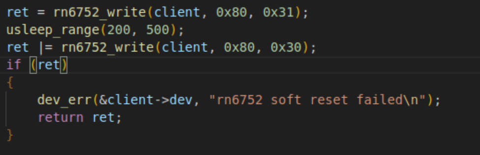
ret = rn6752_write(client, 0x80, 0x31);
usleep_range(200, 500);
ret |= rn6752_write(client, 0x80, 0x30);
if (ret)
{
    dev_err(&client->dev, "rn6752 soft reset failed\n");
    return ret;
}
Split screen during operation, when the image is running normally and is interfered with by a hardware part, it can also lead to a split screen. For example, splitting the screen when connected to CSI0, but not when connected to CSI1, is because its CSI0 channel goes through the VICP module, while CSI1 is directly connected to the ISP module. This is due to the fact that the VICP did not enable the image abnormality detection function. To fix this issue, simply add the abnormality detection function to the CIF channel. For specific operations, refer to the settings for VICAP abnormal reset.
3.11 How to Increase ISP Frequency
On the RV1106/RV1103 platform, to address issues such as slow data output, slow ISP processing speed, and system lag in certain scenarios, it may be necessary to increase the ISP frequency. The following steps can be taken:
# cat /proc/clk/summary | grep isp
        clk_core_isp3p2       1        1        0   339428572          0     0
 50000
        aclk_isp3p2           1        1        0   339428572          0     0
 50000
        hclk_isp3p2           1        1        0   148500000          0     0
 50000
        isp0clk_vicap         2        2        0           0          0     0
 50000
set clk rate: echo [clk_name] [rate(Hz)] > /proc/clk/rate For example:
# echo clk_core_isp3p2 420000000 > /proc/clk/rate

# cat /proc/clk/summary | grep isp
            aclk_isp3p2           1        1        0   339428572          0
0  50000
            hclk_isp3p2           1        1        0   148500000          0
0  50000
            clk_core_isp3p2       1        1        0   420000000          0
0  50000
            isp0clk_vicap         2        2        0           0          0
0  50000
4. 3A Related Issues
If the Sensor requires 3A tuning, such as when the Sensor output format is RAW BAYER RGB like RGGB, BGGR, etc., then image processing needs to be provided by RKISP. Depending on the version of camera_engine_rkaiq, there are differences in the 3A processing method. It is recommended to upgrade to the latest version of camera_engine_rkaiq whenever possible. Please first confirm whether the module is on the support list, If it is already on the support list, there will be a corresponding json file under the directory media/isp/camera_engine_rkaiq/rkaiq/iqfiles/ Otherwise, please initiate a module debugging request to the business window.
4.1 How to Confirm the Version of camera_engine_rkaiq
Check from the source code
# grep RK_AIQ_VERSION_REAL media/isp/camera_engine_rkaiq/rkaiq/RkAiqVersion.h

#define RK_AIQ_VERSION_REAL_V "v5.0x5.0"
4.1.1 How to Confirm the Required rkisp Kernel Driver Version for
camera_engine_rkaiq
The camera_engine_rkisp requires a specific version of the rkisp kernel driver, ensuring that the rkisp driver is up-to-date. Check the ISP Driver Version from the Kernel Source Code
# grep RKISP_DRIVER_VERSION drivers/media/platform/rockchip/isp/version.h
Check the ISP Driver Version from the Kernel Log
  # dmesg | grep "version"

dmesg | grep "version"
[    0.848252] udevd[65]: starting version 3.2.7
[    3.889404] imx415 4-001a: driver version: 00.01.08
[    3.967388] os04a10 4-0036: driver version: 00.01.05
[    4.084418] sc4336 4-0030-3: driver version: 00.01.01
[    4.114867] sc3336 4-0030-1: driver version: 00.01.01
[    4.152066] sc530ai 4-0030: driver version: 00.01.01
[    4.180572] sc200ai 4-0030-6: driver version: 00.01.09
[    4.237776] rkcif rkcif-mipi-lvds: rkcif driver version: v00.02.00
[    4.260419] rkisp rkisp-vir0: rkisp driver version: v02.05.00
4.2 Upgrading camera_engine_rkaiq
The process consists of three parts:
- The camera_engine_rkaiq Located in the SDK’s media/isp/camera_engine_rkaiq directory, it can be updated directly using git or repo tools. It is possible to update only this directory without affecting other directories within the SDK.
- The kernel should be upgraded accordingly based on the requirements of camera_engine_rkaiq By checking the git log in the media/isp/camera_engine_rkaiq directory, you can find the version number of the kernel rkisp driver it requires. For example:
 # git log
commit 3d71d22e1e1cc080cd299b914e4e8daac2a58329
Author: ZhongYichong <zyc@rock-chips.com>
Date:   Sun Feb 18 10:17:18 2024 +0800

    release v5.0x5.0

    cherry-pick:
    6227d46 Revert "fastboot: remove rk_aiq_uapi2_sysctl_preInit_tb_info"
    f8efdd6 Revert "fastboot: _first_awb_cfg use pointer replace struct"
4.3 How to Confirm if 3A is Working Normally
By capturing images to check if the color and exposure of the images are normal. At the same time, check if there is a running process named rkisp_3A_server in the background as follows:
# ps -ef | grep rkisp_3A_server
  706 root      9176 S    /usr/bin/rkisp_3A_server --mmedia=/dev/media1
  746 root      2408 S    grep rkisp_3A_server
# pidof rkisp_3A_server
706
It can be seen that the process ID 706 is rkisp_3A_server.
4.3.1 No rkisp_3A_server Process Detected
First, confirm the existence of the executable file /usr/bin/rkisp_3A_server. If it does not exist, please check the version and compilation of camera_engine_rkaiq. Check for any rkisp_3A-related errors in /var/log/syslog. If errors are found, check the specific error and whether it is due to the inability to locate or mismatch of the Sensor module’s IQ file (xxx.json). Execute rkisp_3A_server –mmedia=/dev/media0 in the shell (if there are multiple /dev/media devices, select the one corresponding to /dev/video), and capture images from another shell. Obtain the error information corresponding to rkisp_3A_server.
4.3.2 How is rkisp_3A_server Started
In the Linux SDK, the rkisp_3A_server is initiated by the script /etc/init.d/S40rkisp_3A and runs in the background. If the /etc/init.d/S40rkisp_3A file is not found, check the version of camera_engine_rkisp and the buildroot package compilation script.
4.3.3 How to Determine the Sensor IQ Configuration File Name and Path
The Sensor IQ file consists of three parts: Sensor Type, such as sc200ai. Module Name, defined in the dts, for example, on the rv1106g2 rk evb board, the name is “CMK-OT2115-PC1”: rockchip,camera-module-name = “CMK-OT2115-PC1”; Module Lens Name, defined in the dts, such as the following “30IRC-F16”: rockchip,camera-module-lens-name = “30IRC-F16”; In the example above, the iq file name is: sc200ai_CMK-OT2115-PC1_30IRC-F16.json, and it is stored in the /etc/iqfiles/ directory. Note that case is sensitive.
4.4 How to Manually Adjust Exposure
When manual exposure is required, the rkisp_3A_server process must be terminated first. Then, refer to the rkisp_demo.cpp program or the source code of librkisp_api.so.
4.5 How to Enable librkaiq Log
By setting the environment variable persist_camera_engine_log , the corresponding bits represent the following:
bits:    23-20   19-16 15-12  11-8  7-4   3-0
module: [xcore]  [ISP] [AF]   [AWB] [AEC] [NO]

0: error
1: warning
2: info
3: verbose
4: debug
For example, to enable debug logs for ISP and AWB:
# /etc/init.d/S40rkisp_3A stop
# export persist_camera_engine_log=0x040400
# /usr/bin/rkisp_3A_server &
4.6 How to Modify Resolution in Sensor IQ File
Assuming you already have an IQ effect file corresponding to the Sensor, and you need to modify the resolution in this file to obtain another IQ file with a different resolution, you can follow these steps: Modify the width and height of the sensor_calib field to the desired dimensions. Search for the keywords of the original resolution in the original IQ file and replace all of them with the expected target resolution size. Modification of the LSC module array Search for lsc_v2, and modify the arrays lsc_sect_size_x and lsc_sect_size_y. Each element of the lsc_sect_size_x array is dst_width / 16, and there are a total of 16 elements; Each element of the lsc_sect_size_y array is dst_height / 16, and there are a total of 16 elements; Note: Due to the existence of multiple scenarios (daytime, nighttime, hdr), all lsc_v2’s lsc_sect_size_x and lsc_sect_size_y in the IQ file must be modified.
5. Application Development Related
C Language Reference Demo RK provides a Linux SDK that includes the rkisp_demo tool and its source code. rkisp_demo is a simple tool for capturing images. Similar to the v4l2-ctl tool, rkisp_demo does not display images; it is primarily provided as a reference for the source code. The source code is located in the <SDK>/media/isp/camera_engine_rkaiq/rkisp_demo directory. The IPC SDK provided by RK includes sample demo source code and simple demo source code. The sample demo is a sample program developed by RK based on the rockit multimedia library and rkaiq library. It provides related applications for different modules or functions. The source code is located in the <SDK>/media/samples/example directory:
.
├── audio
│   ├── Makefile
│   ├── sample_ai_aenc.c
│   └── sample_ai.c
├── avs
│   ├── Makefile
│   ├── sample_avs.c
│   └── sample_multi_vi_avs.c
├── common
│   ├── fillimage.c
│   ├── isp2.x
│   ├── isp3.x
│   ├── lib
│   ├── loadbmp.c
│   ├── loadbmp.h
│   ├── Makefile
│   ├── sample_comm_aenc.c
│   ├── sample_comm_ai.c
│   ├── sample_comm_ao.c
│   ├── sample_comm_avs.c
│   ├── sample_comm.c
│   ├── sample_comm.h
│   ├── sample_comm_iva.c
│   ├── sample_comm_ivs.c
│   ├── sample_comm.o
│   ├── sample_comm_rgn.c
│   ├── sample_comm_tde.c
│   ├── sample_comm_venc.c
│   ├── sample_comm_vi.c
│   ├── sample_comm_vo.c
│   ├── sample_comm_vpss.c
├── demo
│   ├── Makefile
│   ├── sample_demo_aiisp.c
│   ├── sample_demo_dual_aiisp.c
│   ├── sample_demo_dual_camera.c
│   ├── sample_demo_dual_camera_wrap.c
│   ├── sample_demo_multi_camera_eptz.c
│   ├── sample_demo_vi_avs_venc.c
│   ├── sample_demo_vi_venc.c
│   └── sample_rv1103_dual_memory_opt.c
├── Makefile
├── out
│   ├── bin
│   └── install_to_userdata
├── test
│   ├── Makefile
│   ├── sample_ai_aenc_adec_ao_stresstest.c
│   ├── sample_avs_stresstest.c
│   ├── sample_demo_aiisp_stresstest.c
│   ├── sample_demo_dual_aiisp_stresstest.c
│   ├── sample_demo_vi_avs_venc_stresstest.c
│   ├── sample_demo_vi_venc_stresstest.c
│   ├── sample_isp_stresstest.c
│   ├── sample_mulit_isp_stresstest.c
│   ├── sample_rgn_stresstest.c
│   ├── sample_venc_stresstest.c
│   ├── sample_vpss_stresstest.c
│   └── source
├── venc
│   ├── Makefile
│   ├── sample_multi_vi_avs_osd_venc.c
│   └── sample_vi_vpss_osd_venc.c
├── vi
│   ├── Makefile
│   ├── sample_multi_vi.c
│   ├── sample_vi.c
│   └── sample_vi_eis.c
└── vo
    ├── Makefile
    └── sample_vi_vo.c
The demo directory provides application examples, the test directory provides stress test application examples. Other directories are divided according to functional modules such as common, VI, VO, VENC, AUDIO, AVS, etc.
6. Fast Boot Related
6.1 DTS Modification
- Based on the specific device board’s hardware schematic, correctly configure the Sensor- related connection relationships, power-on/off pins, and power domain configurations.
- Correctly configure the rkisp_thunderboot fast boot memory allocation, and configure the size and offset of ramdisk_r and ramdisk_c according to the actual resolution of the Sensor and the number of VICAP offline frame buffers. RV1106 / RV1103:
&rkisp_thunderboot {
    /* reg's offset MUST match with RTOS */
    /*
    * vicap, capture raw10, ceil(w*10/8/256)*256*h *4(buf num)
    * e.g. 2304x1296: 0xf30000
    */
 // 2560 x 1440: 0x1248000
    reg = <0x00860000 0x1248000>;

&ramdisk_r {
reg = <0x1aa8000 (10 * 0x00100000)>;
};

&ramdisk_c {
    reg = <0x24a8000 (5 * 0x00100000)>;
};
RV1103B / RV1106B:
&rkisp_thunderboot {
    /* reg's offset MUST match with RTOS */
    /*
     * vicap, capture raw10, ceil(w*10/8/256)*256*h *3(buf num) +
sizeof(rkisp_thunderboot_resmem_head)
     * In RV1103B the size of rkisp_thunderboot_resmem_head is 0x9000, and it
is 0x6000 in RV1103/RV1106
     * e.g. 2688x1520: 0xf96000(raw picture size) + 0x9000 = 0xf9f000
     */
    reg = <0x00860000 0xf9f000>;
};

&ramdisk_r {
    reg = <0x17ff000 (10 * 0x00100000)>;
};

&ramdisk_c {
    reg = <0x21ff000 (4 * 0x00100000)>;
};
6.2 Kernel Sensor Driver
- Following the guidance document “Rockchip_RV1106_RV1103_Quick_Start_Linux_Battery_IPC_Doorbell_CN.md”, modify the current Sensor driver to add code that supports the fast boot solution. Note: In the fast boot solution, the Sensor register sequence is not configured in the start stream interface, only the start stream register is written.
static int __sc401ai_start_stream(struct sc401ai *sc401ai)
{
    int ret;

    if (!sc401ai->is_thunderboot) {
        ret = sc401ai_write_array(sc401ai->client, sc401ai->cur_mode->reg_list);
        if (ret)
            return ret;

        /* In case these controls are set before streaming */
        ret = __v4l2_ctrl_handler_setup(&sc401ai->ctrl_handler);
        if (ret)
            return ret;
    }

    // Only write the start stream register.
    return sc401ai_write_reg(sc401ai->client,
                             SC401AI_REG_CTRL_MODE,
                             SC401AI_REG_VALUE_08BIT,
                             SC401AI_MODE_STREAMING);
}
- The Sensor driver must properly configure the exposure, gain, and VBLANK interfaces, otherwise, abnormal screen conditions may occur.
static int sc401ai_set_ctrl(struct v4l2_ctrl *ctrl)
{
    ......

    switch (ctrl->id) {
    case V4L2_CID_EXPOSURE:  // Exposure
        if (sc401ai->cur_mode->hdr_mode == NO_HDR) {
        val = ctrl->val << 1;
        /* 4 least significant bits of exposure are fractional part */
        ret = sc401ai_write_reg(sc401ai->client,
                                 SC401AI_REG_EXPOSURE_H,
                                 SC401AI_REG_VALUE_08BIT,
                                 SC401AI_FETCH_EXP_H(val));
        ret |= sc401ai_write_reg(sc401ai->client,
                                  SC401AI_REG_EXPOSURE_M,
                                  SC401AI_REG_VALUE_08BIT,
                                  SC401AI_FETCH_EXP_M(val));
        ret |= sc401ai_write_reg(sc401ai->client,
                                  SC401AI_REG_EXPOSURE_L,
                                  SC401AI_REG_VALUE_08BIT,
                                  SC401AI_FETCH_EXP_L(val));
    }
    break;
case V4L2_CID_ANALOGUE_GAIN:  // Analog Gain
    if (sc401ai->cur_mode->hdr_mode == NO_HDR)
        ret = sc401ai_set_gain_reg(sc401ai, ctrl->val);
    break;
case V4L2_CID_VBLANK:  // VBLANK, affects frame rate
    ret = sc401ai_write_reg(sc401ai->client,
                             SC401AI_REG_VTS_H,
                             SC401AI_REG_VALUE_08BIT,
                             (ctrl->val + sc401ai->cur_mode->height)
                             >> 8);
    ret |= sc401ai_write_reg(sc401ai->client,
                              SC401AI_REG_VTS_L,
                              SC401AI_REG_VALUE_08BIT,
                              (ctrl->val + sc401ai->cur_mode->height)
                              & 0xff);
    if (!ret)
        sc401ai->cur_vts = ctrl->val + sc401ai->cur_mode->height;
    sc401ai_modify_fps_info(sc401ai);
    break;
case V4L2_CID_TEST_PATTERN:  // pattern test mode
    ret = sc401ai_enable_test_pattern(sc401ai, ctrl->val);
    break;
case V4L2_CID_HFLIP:  // Horizontal mirror
    ret = sc401ai_read_reg(sc401ai->client, SC401AI_FLIP_MIRROR_REG,
                            SC401AI_REG_VALUE_08BIT, &val);
    ret |= sc401ai_write_reg(sc401ai->client,
                              SC401AI_FLIP_MIRROR_REG,
                              SC401AI_REG_VALUE_08BIT,
                              SC401AI_FETCH_MIRROR(val, ctrl->val));
    break;
case V4L2_CID_VFLIP:  // Vertical flip
    ret = sc401ai_read_reg(sc401ai->client, SC401AI_FLIP_MIRROR_REG,
                            SC401AI_REG_VALUE_08BIT, &val);
    ret |= sc401ai_write_reg(sc401ai->client,
                              SC401AI_FLIP_MIRROR_REG,
                              SC401AI_REG_VALUE_08BIT,
                              SC401AI_FETCH_FLIP(val, ctrl->val));
    break;

    ......
    }

    pm_runtime_put(&client->dev);
    return ret;
}
6.3 MCU RTT Sensor Driver Related Issues
When developing the RTT Sensor driver, the following points should be noted:
- In the RTT Sensor driver, the register configuration for both low and high resolutions should not include settings for the MIPI enable or registers that control the Sensor to start stream. If configured, it will cause an abnormal AE convergence during the RTT phase. When switching to the kernel to fetch the stream at the high-resolution image, it will not be possible to do it.
static const uint8_t g_sc401ai_2560x1440_30fps_reg_table[] = {
    ......
    0x3,  0x36,  0xf9,  0x14,
    // 0x3,  0x01,  0x00,  0x01,  // The 0x0100 register, which used to start
stream of the sensor, should not be configured
    0x3a,
}
- The calculation of exposure and gain values in the RTT Sensor driver should follow the method used in the kernel Sensor driver.
6.4 Sensor IQ Files
To use the correct IQ file, convert the IQ file from JSON format to BIN format as follows:
./media/isp/release_camera_engine_rkaiq_rv1106_arm-rockchip830-linux-
uclibcgnueabihf/host/j2s4b input_json_file output_bin_file
To quickly compile after modifying the IQ file: The IQ BIN file can be placed directly in the output/out/media_out/isp_iqfiles directory,
cd output/out/media_out/isp_iqfiles
Use the j2s4b tool for conversion:
../host/j2s4b mis2032_CMK-OT2115-PC1_30IRC-F16.json mis2032_CMK-OT2115-
PC1_30IRC-F16.bin
Compile the meta partition and flash the meta partition firmware:
cd -
./build.sh meta
Alternatively, you can push the IQ BIN file to the board, refer to the SDK documentation, update the meta partition parameter sensor_iq_bin, and restart to take effect. For the issue of the first few frames showing green in the stream of fast boot: Consider the possibility of AWB or exposure anomalies, and you may enable the earlierAwbAct feature in the JSON file;
"earlierAwbAct": {
  "enable": 1,
  ...
}
At the same time, disable the CAC module:
"cac_v11": {
  "SettingPara": {
    "enable": 0,
  }
}
6.5 Issue Resolution
6.5.1 Not Found Main Camera Sensor Configuration Error
When compiling firmware, an issue may arise where the main camera sensor configuration cannot be found, as shown below:
[build_meta.sh:error] Not found main camera sensor config, please add
[support_sensors] in build_meta.sh
Resolution Steps: First, check if the iq file exists and ensure that the build_meta.sh script has added the supported Sensor. Modify the board-level configuration to set RK_CAMERA_SENSOR_IQFILES to the IQ file of the current Sensor. Place the IQ bin file for the corresponding Sensor directly in the output/out/media_out/isp_iqfiles directory, then compile the kernel and firmware. Re-flash the boot partition.
6.5.2 Light Sensitivity Configuration Issues
During the rtt operation, the following error occurred:
Meta: ok
## Verified-boot: 0

iq_bin_mode=0
scene(day) frmRate: mode=0, val=25, keep fps
scene(night) frmRate: mode=1, val=25, update fps=15
load iq bin file finished!
gc5603-sensor_0 cur resolution, width 1480, height 832, fps 60!
gc5603-sensor_0 find dst resolution, width 2880, height 1616, fps 15!
[FASTAE]: fps/hts/vts: RTT=[60, 3223, 875], MainAIQ=[15, 3200, 3500]
[AELIB]: fastae: 3.0.5
[FASTAE]: ADC run failed! can't find rk_adc0 device!
Illegal instruction
This is generally due to an error in the light sensitivity configuration in meta. Types of light sensitivity include: Software Light Sensitivity, Analog Light Sensitivity, Digital Light Sensitivity.
typedef enum  {
    ALS_TYPE_NONE    = 0,   // Software Light Sensitivity
    ALS_TYPE_ANALOG  = 1,   // Analog Light Sensitivity
    ALS_TYPE_DIGITAL = 2,   // Digital Light Sensitivity
} eALS_TYPE;
In procject/make_meta/sensor_init/xxx_init.c: Configure the correct type according to the type of light sensitivity selected in the actual project.
.als_type = ALS_TYPE_ANALOG,
.als_value = FIX2INT16(10.0),
Note: When setting Analog Light Sensitivity ALS_TYPE_ANALOG, the relevant sensor’s board config needs to have the following configuration enabled: SDK/sysdrv/source/mcu/rt-thread/bsp/rockchip/xxx_mcu/board/: CONFIG_RT_USING_SARADC=y When setting Software Light Sensitivity ALS_TYPE_NONE, the relevant sensor’s board config should not have the following configuration enabled: #CONFIG_RT_USING_SARADC is not set
6.5.3 Kernel Crash
After RTT starting and switches to kernel boot, it crashes with an exception of rk_csirx_irq1_handler . The reason is that the host driver has been properly registered, but during the RTT operation phase, a MIPI error occurs. At this point, it enters the err1 interrupt, but by then, RTT is almost finished, so RTT turns off the host clock, leading to an error when accessing the register during the interrupt.
[    0.274655] [<b037486c>] (rk_csirx_irq1_handler) from [<b022e2a7>]
(__handle_irq_event_percpu+0x25/0x7e)
        [    0.275490] [<b022e2a7>] (__handle_irq_event_percpu) from [<b022e30f>]
(handle_irq_event_percpu+0xf/0x30)
        [    0.276334] [<b022e30f>] (handle_irq_event_percpu) from [<b022e34b>]
(handle_irq_event+0x1b/0x28)
        [    0.277121] [<b022e34b>] (handle_irq_event) from [<b02300d9>]
(handle_fasteoi_irq+0x57/0x90)
        [    0.277864] [<b02300d9>] (handle_fasteoi_irq) from [<b022df6f>]
(__handle_domain_irq+0x4b/0x64)
        [    0.278630] [<b022df6f>] (__handle_domain_irq) from [<b02ee983>]
(gic_handle_irq+0x41/0x4e)
        [    0.279375] [<b02ee983>] (gic_handle_irq) from [<b0208d13>]
(__irq_svc+0x53/0x7c)
Solution: Update the rkcif driver to include interrupt exception handling.
6.5.4 How to Confirm the Output Effect of a Sensor Without a Lens
When confirming the effect of a sensor without a lens, you can activate the pattern test mode to display color bars or grayscale images to check the output image quality. The code for the pattern mode is added in the start flow interface, before setting the start flow register. Taking SC200AI as an example:
#define SC200AI_REG_TEST_PATTERN    0x4501
#define SC200AI_TEST_PATTERN_BIT_MASK   BIT(3)
...
static int sc200ai_enable_test_pattern(struct sc200ai *sc200ai, u32 pattern)
{
    u32 val = 0;
    int ret = 0;

    ret = sc200ai_read_reg(sc200ai->client, SC200AI_REG_TEST_PATTERN,
                           SC200AI_REG_VALUE_08BIT, &val);
    if (pattern)
        val |= SC200AI_TEST_PATTERN_BIT_MASK;
    else
        val &= ~SC200AI_TEST_PATTERN_BIT_MASK;

    ret |= sc200ai_write_reg(sc200ai->client, SC200AI_REG_TEST_PATTERN,
                             SC200AI_REG_VALUE_08BIT, val);
    return ret;
}

static int sc200ai_set_ctrl(struct v4l2_ctrl *ctrl)
{
    ...
    case V4L2_CID_TEST_PATTERN:
        ret = sc200ai_enable_test_pattern(sc200ai, ctrl->val);
        break;
    ...
}
6.5.5 Kernel Continuously Prints MIPI SIZE ERROR After Booting
Ensure that the actual image width and height configured during the RTT phase are correct. Carefully check the sensor register configuration against the manual description.
6.5.6 Failed to stop decompress: decompress@ff520000
When encountering “Failed to stop decompress: decompress@ff520000, ret=-119,” which indicates a kernel decompression failure, you may attempt to resolve the issue by modifying the maximum frequency of the spi_nor node in the file sysdrv/source/uboot/u- boot/arch/arm/dts/rv1106-evb2.dts, reducing it to 100MHz or lower.
&spi nor {
        spi-max-frequency = <125000000> to spi-max-frequency = <100000000>
6.5.7 Failed to stop decompress: decompress@ff520000, ret=-110
When encountering the “Failed to stop decompress: decompress@ff520000, ret=-110” kernel decompression failure situation, try modifying the size of the ramdisk and the CMA (Contiguous Memory Allocator), ensuring that neither is set too large.
6.5.8 How to Set Fast Boot Applications Not to Auto-Start
If the kernel boot script is configured to automatically start fast boot applications upon boot, it may sometimes cause inconvenience during development and debugging. The following meta command can be used to set fast boot applications not to auto-start.
make_meta --update --meta_path /dev/block/by-name/meta --cmdline NoAuto=1
Enable AE log printing while also setting the fast boot application not to auto-start.
make_meta --update --meta_path /dev/block/by-name/meta --cmdline "persist_camera_engine_log=0x1ff4 NoAuto=1"
Note: Currently, only RV1106/RV1103/RV1103B/RV1106B SDK supports this command.
6.5.9 How to Set Up Kernel Log Printing During the Fast Boot Process
Method One: Modify the loglevel=8 in the boot parameters of the corresponding dts, recompile the kernel, and flash the boot partition firmware. Method Two: After booting, enter the command through the serial port
make_meta --update --meta_path /dev/block/by-name/meta --cmdline "loglevel=8"
6.5.10 How to Confirm Whether Sensor Outputs Data in Advance After
RTT Switches to Large Image Configuration
When RTT switches to a large image sequence, it is necessary to confirm whether the sensor starts outputting data in advance. This can be held by spl while 1 without entering the kernel and then measuring the Sensor-related MIPI data waveform using an oscilloscope. cd sysdrv/source/uboot/u-boot:
git diff common/spl/spl.c
diff --git a/common/spl/spl.c b/common/spl/spl.c
index 6836796b4e..070388c066 100644
--- a/common/spl/spl.c
+++ b/common/spl/spl.c
@@ -739,4 +739,5 @@ void spl_cleanup_before_jump(struct spl_image_info
*spl_image)

        us = (get_ticks() - gd->sys_start_tick) / 24UL;
        printf("Total: %ld.%ld ms\n\n", us / 1000, us % 1000);
+       while(1);
}
6.5.11 How to Quickly Locate Offline Frame Issues During the Fast Boot
Phase
The vicap has reserved a debug switch. After activation, it can print the FS/FE interrupts of the first 15 frames, as well as the rotation of the buffer and other debug information. When frame splicing or frame errors occur, the issue can be quickly located by analyzing the relevant logs. Activation method:
diff --git a/drivers/media/platform/rockchip/cif/dev.c
b/drivers/media/platform/rockchip/cif/dev.c
index c3b59414eede3..bb616b1897b58 100644
--- a/drivers/media/platform/rockchip/cif/dev.c
+++ b/drivers/media/platform/rockchip/cif/dev.c
@@ -1957,7 +1957,7 @@ int rkcif_plat_init(struct rkcif_device *cif_dev, struct
device_node *node, int
        cif_dev->sensor_linetime = 0;
        cif_dev->early_line = 0;
        cif_dev->is_thunderboot = false;
-       cif_dev->rdbk_debug = 0;
+       cif_dev->rdbk_debug = 3;

        cif_dev->resume_mode = 0;
        memset(&cif_dev->channels[0].capture_info, 0, sizeof(cif_dev->channels[0].capture_info));
6.5.12 How to Capture Small Images at the RTT Stage and Check the
Effects
In dts, comment out all rkisp, rkcif, and mipi: disabled csi2_dphy_hw:disabled csi2_dphy0:disabled mipi0_csi2:disabled rkcif:disabled rkcif_mipi_lvds:disabled rkcif_mipi_lvds_sditf:disabled rkisp:disabled rkisp_vir0:disabled Use the command io -rf /tmp/1.yuv -l 393216 0x866000 0 to save small image data, which can only save the last 5 frames of data. You can force a modification by setting fastae_max_run_frame=5
[STREAM]: L 0, 1, 0, 0x866000, 783360, 0x45d, 0x8000, tick:59
[STREAM]: L 1, 2, 0, 0x926000, 783360, 0x45d, 0x8000, tick:76
[STREAM]: L 2, 3, 0, 0x9e6000, 783360, 0x45d, 0x8000, tick:87
[STREAM]: L 3, 4, 0, 0xaa6000, 783360, 0x45d, 0x1828, tick:98
[STREAM]: L 4, 5, 0, 0xb66000, 783360, 0x45d, 0x48d, tick:109
Addresses such as 0x866000, 0x926000, etc., represent the last few frames of data saved during the RTT stage.
6.5.13 First Frame Image Color Abnormality
When the first frame image appears too dark or too green, it is generally due to an incorrect IQ file, leading to abnormal AWB (Automatic White Balance) and causing the anomaly. In the following RTT log, the luma brightness has a very small value, resulting in a dark first frame:
[FASTTAE]: >>> als type: 1, als value: 0xa0000, night mode: 0
start_stream 278 tick 23
[isp_0]:rk_isr_hw_set_vicap_clk enable is 1
[FASTAE]: set_firstae 1733 tick 23
[STREAM]: L 0, 1, 0, 0x866000, 178r400, 0x2, 0x40, tick:43
[AELIB]: 1,luma=1.0000,setpoint=60.0000,curexp=0.0000,newexp=0.0000,T?
8.0000,G=1.0000,ispG=1.0000,regT=2,regG=64

[STREAM]: L 1, 2, 0, 0x9b80000 1382400, 0x2, 0x40, tick:62
[AELIB]:2,luma=1.0000,setpoint=60.0000,curexp=0.0000,newexp=0.0000,T=0.0000,G=1.0
000,ispG=1.0000 regT=2,regG=64

[STREAM]: L 2, 3, 0, 0xb0a000, 138r400, 0x2, 0x40, tick:80
[AELIB]: 3,luma=1.0000,setpoint=60.0000,curexp=0.0000 ==========fastae is
match===========
Solution: Check if the earlierAwbAct parameter in the IQ file is enabled and configured correctly. As follows:
"earlierAwbAct":    {
        "enable":   1,
        "mode": "CALIB_AWB_EARLACT_XYREG_FIXED",
        "xyRegion": [{
        "normal":   [-161, 286, 81, -95],
        "big":  [-161, 286, 112, -125]
        }, {
        "normal":   [-803, -161, 135, -199],
        "big":  [-803, -161, 185, -224]
        }, {
        "normal":   [-1467, -796, 121, -78],
        "big":  [-1559, -796, 136, -93]
        }, {
        "normal":   [-2062, -1535, 65, -130],
        "big":  [-2017, -1535, 130, -130]
        }]
    }
Note: For quick start applications, it is necessary to enable the earlierAwbAct function in the JSON to adjust AWB as soon as possible. Normally, AWB takes 2 frames to calculate a result. Without fast AWB, it uses the initial AWB value, and the WB gain is 1, which results in a green color. For fast boot, it is required that during tuning, earlierawb is enabled, AUTO mode is selected, and the corresponding parameters are filled in.
7. AOV Related
7.1 How to Support Sensor Hardware Standby Mode
Standby mode refers to the state where the Sensor, in order to reduce power consumption, is in a sleep or reset mode. Sleep Mode The Sensor stops the image data stream and operates in a low-power state, maintaining the current register values. Taking SC200AI as an example, there are two ways to enter sleep mode:
- Pull the PWDN low, at which point I2C read and write are not supported.
- Write the stream control register to 0, at which point I2C read and write are supported. Reset Mode The Sensor stops the image data stream and operates in a low-power state, resetting all registers. Taking SC200AI as an example, there are two ways to enter reset mode:
- Pull the XSHUTDN low, at which point I2C read and write are not supported.
- Write the soft enable reset register to 1, and this reset mode lasts for 150ns. Hardware standby mode: refers to the Sensor entering sleep mode by pulling the PWDN pin low, thus operating in a low-power state where I2C is not readable or writable. Taking SC200AI as an example, in the dts, the Sensor node adds the attribute rockchip,camera- module-stb = <1> to support the hardware standby mode. The value of this attribute indicates whether the hardware standby mode is supported, with 1 indicating support and 0 indicating no support.
sc200ai: sc200ai@30 {
    compatible = "smartsens,sc200ai";
    status = "okay";
    reg = <0x30>;
    ...
    rockchip,camera-module-stb = <1>;
    port {
        sc200ai_out: endpoint {
            remote-endpoint = <&csi_dphy_input1>;
            data-lanes = <1 2>;
        };
    };
};
In the Sensor driver probe interface, it is necessary to add parsing for this attribute value to determine whether the hardware standby mode is supported and to save it in the sc200ai- >standby_hw member variable.
If the hardware standby mode is supported, in the ioctl processing interface, the quick_stream command will pull the relevant PWDN GPIO up or down according to the stream start and stop state. During sleep and wake-up, a v4l2 ioctl command will be issued to reset the exposure, gain registers, etc.
    case RKMODULE_SET_QUICK_STREAM:
        stream = *((u32 *)arg);
        if (sc200ai->standby_hw) { // hardware standby
            if (stream) {
                if (!IS_ERR(sc200ai->pwdn_gpio))
                    gpiod_set_value_cansleep(sc200ai->pwdn_gpio, 1);
                ret = sc200ai_write_reg(sc200ai->client, SC200AI_REG_MIPI_CTRL,
                    SC200AI_REG_VALUE_08BIT, SC200AI_MIPI_CTRL_ON);

                ret |= sc200ai_write_reg(sc200ai->client, SC200AI_REG_CTRL_MODE,
                    SC200AI_REG_VALUE_08BIT, SC200AI_MODE_STREAMING);

                dev_info(&sc200ai->client->dev, "quickstream, streaming on: exit standby mode\n");
                sc200ai->is_standby = false;
            } else {
                ret = sc200ai_write_reg(sc200ai->client, SC200AI_REG_CTRL_MODE,
                    SC200AI_REG_VALUE_08BIT, SC200AI_MODE_SW_STANDBY);

                ret |= sc200ai_write_reg(sc200ai->client, SC200AI_REG_MIPI_CTRL,
                    SC200AI_REG_VALUE_08BIT, SC200AI_MIPI_CTRL_OFF);

                if (!IS_ERR(sc200ai->pwdn_gpio))
                    gpiod_set_value_cansleep(sc200ai->pwdn_gpio, 0);

                dev_info(&sc200ai->client->dev, "quickstream, streaming off: enter standby mode\n");
                sc200ai->is_standby = true;
            }
        } else {    // software standby
            ...
        }
For further reference, please see the SC200AI driver. Software Standby Mode: Software standby mode refers to the method where, after entering sleep & wake-up, the complete Sensor register configuration is written, and then in the Sensor ioctl interface, the quick_stream command is processed directly to configure the sleep & wake-up mode of the stream register.
......
} else {    // software standby
        if (stream) {
            ret = sc200ai_write_reg(sc200ai->client, SC200AI_REG_MIPI_CTRL,
                    SC200AI_REG_VALUE_08BIT, SC200AI_MIPI_CTRL_ON);

            ret |= sc200ai_write_reg(sc200ai->client, SC200AI_REG_CTRL_MODE,
                    SC200AI_REG_VALUE_08BIT, SC200AI_MODE_STREAMING);
            dev_info(&sc200ai->client->dev, "quickstream, streaming on: exit soft standby mode\n");
       } else {
           ret = sc200ai_write_reg(sc200ai->client, SC200AI_REG_CTRL_MODE,
                                   SC200AI_REG_VALUE_08BIT,
SC200AI_MODE_SW_STANDBY);

           ret |= sc200ai_write_reg(sc200ai->client, SC200AI_REG_MIPI_CTRL,
                                    SC200AI_REG_VALUE_08BIT,
SC200AI_MIPI_CTRL_OFF);
           dev_info(&sc200ai->client->dev, "quickstream, streaming off: enter soft standby mode\n");
        }
}
7.2 Controlling the Fill Light
In AOV mode, it is possible to control the fill light. Each Sensor can control one fill light, and both PWM and GPIO types of fill lights are supported. The control settings are as follows:
- Add a light_ctl node in the board-level configuration DTS, and in the node properties, add the control devices or pins corresponding to the PWM and GPIO of the fill light based on the actual hardware connection. Here is an example: the fill light is controlled by the pwm7 device, with an index of 0, and the gpio is not used.
/ {
    model = "Rockchip RV1106G EVB2 V10 Board";
    compatible = "rockchip,rv1106g-evb2-v10", "rockchip,rv1106";

    chosen {
        bootargs = "loglevel=0 rootfstype=erofs rootflags=dax console=ttyFIQ0 root=/dev/rd0 snd_soc_core.prealloc_buffer_size_kbytes=16 coherent_pool=0 driver_async_probe=dwmmc_rockchip";
    };
    ...
    light_ctrl: light-ctl {
        compatible = "rockchip,light-ctl";
        pwms=<&pwm7 0 25000 0>;
        light-gpios =<&gpio3 RK_PD2 GPIO_ACTIVE_HIGH>;
        rockchip,module-index = <0>;
        status = "okay";
    };
};
- Enable the CONFIG_LIGHT_CTL configuration in the kernel settings.
- Add the relevant control interfaces in the Sensor driver.
 #include <linux/clk.h>
@@ -40,8 +41,9 @@
 #include "../platform/rockchip/isp/rkisp_tb_helper.h"
 #include "cam-tb-setup.h"
 #include "cam-sleep-wakeup.h"
+#include "light_ctl.h"

-#define DRIVER_VERSION         KERNEL_VERSION(0, 0x01, 0x09)
+#define DRIVER_VERSION         KERNEL_VERSION(0, 0x01, 0x10)

 #ifndef V4L2_CID_DIGITAL_GAIN
 #define V4L2_CID_DIGITAL_GAIN      V4L2_CID_GAIN
@@ -192,6 +194,7 @@ struct sc200ai {
    bool            is_standby;
    struct preisp_hdrae_exp_s init_hdrae_exp;
    struct cam_sw_info  *cam_sw_inf;
+   struct rk_light_param   light_ctl_param;
 };

 #define to_sc200ai(sd) container_of(sd, struct sc200ai, subdev)
@@ -1191,6 +1194,8 @@ static long sc200ai_ioctl(struct v4l2_subdev *sd,
unsigned int cmd, void *arg)
    u32 i, h, w;
    long ret = 0;
    u32 stream = 0;
+   int rt = 0;
+   struct rk_light_param *light_param;

    switch (cmd) {
    case RKMODULE_GET_MODULE_INFO:
@@ -1238,6 +1243,22 @@ static long sc200ai_ioctl(struct v4l2_subdev *sd,
unsigned int cmd, void *arg)

        stream = *((u32 *)arg);

+       dev_err(&sc200ai->client->dev, "%s: quick_stream = %d\n",
+           __func__, stream);
+       // light control
+       if (stream) {
+           sc200ai->light_ctl_param.light_enable = true;
+           rt = light_ctl_write(sc200ai->module_index,
+                        &sc200ai->light_ctl_param);
+       } else {
+           sc200ai->light_ctl_param.light_enable = false;
+           rt = light_ctl_write(sc200ai->module_index,
+                        &sc200ai->light_ctl_param);
+       }
+
+       dev_err(&sc200ai->client->dev, "%s: light_ctl_write ret:%d\n",
+            __func__, rt);
+
        if (sc200ai->standby_hw) { // hardware standby
            if (stream) {
                if (!IS_ERR(sc200ai->pwdn_gpio))
@@ -1284,6 +1305,18 @@ static long sc200ai_ioctl(struct v4l2_subdev *sd,
unsigned int cmd, void *arg)
        ch_info = (struct rkmodule_channel_info *)arg;
        ret = sc200ai_get_channel_info(sc200ai, ch_info);
        break;
+
+   case RKCIS_CMD_FLASH_LIGHT_CTRL:
+       light_param = (struct rk_light_param *)arg;
+       dev_err(&sc200ai->client->dev,
+           "%s: RKCIS_CMD_FLASH_LIGHT_CTRL type: %s enable: %s\n",
+           __func__,
+           light_param->light_type == LIGHT_PWM ? "pwm" : "gpio",
+           light_param->light_enable ? "enable" : "disable");
+
+       memcpy(&sc200ai->light_ctl_param, light_param, sizeof(*light_param));
+
+       break;
    default:
        ret = -ENOIOCTLCMD;
        break;
@@ -1304,6 +1337,7 @@ static long sc200ai_compat_ioctl32(struct v4l2_subdev
*sd,
    struct rkmodule_channel_info *ch_info;
    long ret;
    u32 stream = 0;
+   struct rk_light_param *light_param = NULL;

    switch (cmd) {
    case RKMODULE_GET_MODULE_INFO:
@@ -1400,6 +1434,19 @@ static long sc200ai_compat_ioctl32(struct v4l2_subdev
*sd,
        }
        kfree(ch_info);
        break;
+   case RKCIS_CMD_FLASH_LIGHT_CTRL:
+       light_param = kzalloc(sizeof(*light_param), GFP_KERNEL);
+       if (!light_param) {
+           ret = -ENOMEM;
+           return ret;
+       }
+       ret = copy_from_user(light_param, up, sizeof(*light_param));
+       if (!ret)
+           ret = sc200ai_ioctl(sd, cmd, light_param);
+       else
+           ret = -EFAULT;
+       kfree(light_param);
+       break;
    default:
        ret = -ENOIOCTLCMD;
        break;
@@ -1451,6 +1498,10 @@ static int __sc200ai_stop_stream(struct sc200ai
*sc200ai)
        sc200ai->is_first_streamoff = true;
        pm_runtime_put(&sc200ai->client->dev);
    }
+   sc200ai->light_ctl_param.duty_cycle = 0;
+   sc200ai->light_ctl_param.light_enable = false;
+   light_ctl_write(sc200ai->module_index,
+           &sc200ai->light_ctl_param);
    return sc200ai_write_reg(sc200ai->client, SC200AI_REG_CTRL_MODE,
                 SC200AI_REG_VALUE_08BIT, SC200AI_MODE_SW_STANDBY);
 }
@@ -1973,6 +2024,7 @@ static int sc200ai_initialize_controls(struct sc200ai
*sc200ai)
    sc200ai->subdev.ctrl_handler = handler;
    sc200ai->has_init_exp = false;
    sc200ai->is_standby = false;
+   sc200ai->light_ctl_param.duty_cycle = 0;

    return 0;
- Application code example:
--- a/sample_aov_vi.c
+++ b/sample_aov_vi.c
@@ -572,6 +572,19 @@ int main(int argc, char *argv[]) {
        if (!ctx->vi.bIfQuickStart) {
                RK_MPI_VI_StartPipe(ctx->vi.u32PipeId);
        }
+
+       // Enable VI light
+       VI_LIGHT_CTL_PARAM_S tLightCtlParam;
+       printf("%s - VI_LIGHT_CTL_PARAM_S size:%d\n", __func__,
sizeof(VI_LIGHT_CTL_PARAM_S));
+       memset(&tLightCtlParam, 0, sizeof(tLightCtlParam));
+       tLightCtlParam.light_enable = RK_TRUE;
+       tLightCtlParam.light_type = LIGHT_TYPE_PWM;
+       tLightCtlParam.duty_cycle = 25000;
+       tLightCtlParam.period = 25000;
+       tLightCtlParam.polarity = 0;
+
+       RK_MPI_VI_DevEnableLight(ctx->vi.s32DevId, ctx->vi.s32DevId,
&tLightCtlParam);
+
        if (s32ViFrameMode == 0)
                pthread_create(&vi_thread_id, 0, vi_get_stream, (void *)
(&ctx->vi));
7.3 AOV Development Reference Document
For detailed development documentation related to AOV, please refer to the “Rockchip_RV1106_Developer_Guide_Linux_AOV_CN.md”.
Source code differences
The main text follows its language source; RU/DE follow EN. Different code fragments from the other source are preserved below, including comment/layout differences. These are independent examples, not a combined executable script; source parameters were not silently overwritten.
CN PDF p.6 · 28
# media-ctl -p -d /dev/media0 | tail -n 30
                -> "rkcif_tools_id2":0 []
        pad11: Source
                -> "stream_cif_mipi_id0":0 []
                -> "stream_cif_mipi_id1":0 []
                -> "stream_cif_mipi_id2":0 []
CN PDF p.7 · 29
                -> "stream_cif_mipi_id3":0 []
                -> "rkcif_scale_ch0":0 []
                -> "rkcif_scale_ch1":0 []
                -> "rkcif_scale_ch2":0 []
                -> "rkcif_scale_ch3":0 []
                -> "rkcif_tools_id0":0 []
                -> "rkcif_tools_id1":0 []
                -> "rkcif_tools_id2":0 [ENABLED]

- entity 58: rockchip-csi2-dphy0 (2 pads, 2 links)
             type V4L2 subdev subtype Unknown flags 0
             device node name /dev/v4l-subdev1
        pad0: Sink
                [fmt:SBGGR10_1X10/2688x1520@10000/300000 field:none]
                <- "m00_b_sc450ai 4-0030":0 [ENABLED]
        pad1: Source
                -> "rockchip-mipi-csi2":0 [ENABLED]

- entity 63: m00_b_sc450ai 4-0030 (1 pad, 1 link)
             type V4L2 subdev subtype Sensor flags 0
             device node name /dev/v4l-subdev2
        pad0: Source
                [fmt:SBGGR10_1X10/2688x1520@10000/300000 field:none]
                -> "rockchip-csi2-dphy0":0 [ENABLED]
CN PDF p.7 · 33
+++ b/drivers/media/i2c/sc530ai.c
@@ -1593,8 +1593,8 @@ static int sc530ai_open(struct v4l2_subdev *sd, struct
v4l2_subdev_fh *fh)
 }
 #endif

-#define DST_WIDTH 2880
-#define DST_HEIGHT 1616
+#define DST_WIDTH 2560
+#define DST_HEIGHT 1440
CN PDF p.8 · 37
# i2ctransfer -f -y 4 w3@0x32 0x43 0x24 0x18

4:代表 IIC 的总线号(对应的可为0,1,2,3...)
w:代表写
3:代表写 3 Byte
0x32:代表 IIC 设备地址
后边三个数据代表要写的数据,这⾥0x4324假如为16bit的寄存器地址,0x18为要写⼊的值。

# i2ctransfer -f -y 4 w1@0x30 0x08 r3

4:代表 IIC 的总线号(对应的可为0,1,2,3...)
w:表⽰写
1:表⽰写 1 Byte
0x30:代表 IIC 设备地址
r:代表读取
3:代表读取 3 Byte

这句代表的意思是从0x30地址上偏移0x08之后读取3个Byte,r后数字表⽰读取的个数。
CN PDF p.14 · 84
static const struct ov7251_mode supported_modes[] = {
        {
                .width = 640,
                .height = 480,
CN PDF p.15 · 91
常⻅命令有:
# 取 raw 图
rk_mpi_vi_test -w 1920 -h 1080 -d 0 -c 0 -m 0 -l 10 -n /dev/video0 -f 131076

# 从 mainpath 通道取 yuv 图,并保存在⽂件中。⽂件⽬录 /data/test_0_0_0.bin,可使⽤
7yuv等⼯具打开。⽂件命名根据 dev id, pipe id, chn id相关。
rk_mpi_vi_test -w 1920 -h 1080 -d 0 -c 0 -m 0 -l 10 -o 1

# 从 mainpath 通道取 yuv 图,并并编码,写⽂件。⽂件保存在/data/venc_0.bin,⽂件命名跟
chn id 有关。
rk_mpi_vi_test -w 1920 -h 1080 -d 0 -c 0 -m 1 -l 10 -o 1
...
CN PDF p.15 · 93
# 使⽤ simple_vi_bind_venc_rtsp demo,通过rtsp 实时预览(使⽤vlc 或 potplayer⼯具配
置板端IP).
simple_vi_bind_venc_rtsp -I 0 -w 1920 -h 1080 (rtsp://ip/live/0)
CN PDF p.17 · 116
# media-ctl -p -d /dev/media0
...
- entity 2: rkisp1_mainpath (1 pad, 1 link)              //表⽰该entity是
MP(MainPath)
            type Node subtype V4L flags 0
            device node name /dev/video1                 //对应的设备节点
是/dev/video1
        pad0: Sink
                <- "rkisp1-isp-subdev":2 [ENABLED]

- entity 3: rkisp1_selfpath (1 pad, 1 link)              //表⽰该entity是
SP(SelfPath)
            type Node subtype V4L flags 0
            device node name /dev/video2                 //对应的设备节点
是/dev/video2
        pad0: Sink
                <- "rkisp1-isp-subdev":2 [ENABLED]
...
CN PDF p.17 · 118
# grep '' /sys/class/video4linux/video*/name
/sys/class/video4linux/video0/name:stream_cif
/sys/class/video4linux/video1/name:rkisp1_mainpath       # MP节点对应/dev/video1
/sys/class/video4linux/video2/name:rkisp1_selfpath       # SP节点对应/dev/video2
/sys/class/video4linux/video3/name:rkisp1_rawpath
/sys/class/video4linux/video4/name:rkisp1_dmapath
/sys/class/video4linux/video5/name:rkisp1-statistics
/sys/class/video4linux/video6/name:rkisp1-input-params
CN PDF p.20 · 134
#grep RK_AIQ_VERSION_REAL media/isp/camera_engine_rkaiq/rkaiq/RkAiqVersion.h

#define RK_AIQ_VERSION_REAL_V "v5.0x5.0"
CN PDF p.20 · 139
  # dmesg  | grep "version"

dmesg | grep "version"
[    0.848252] udevd[65]: starting version 3.2.7
[    3.889404] imx415 4-001a: driver version: 00.01.08
[    3.967388] os04a10 4-0036: driver version: 00.01.05
[    4.084418] sc4336 4-0030-3: driver version: 00.01.01
[    4.114867] sc3336 4-0030-1: driver version: 00.01.01
[    4.152066] sc530ai 4-0030: driver version: 00.01.01
[    4.180572] sc200ai 4-0030-6: driver version: 00.01.09
[    4.237776] rkcif rkcif-mipi-lvds: rkcif driver version: v00.02.00
[    4.260419] rkisp rkisp-vir0: rkisp driver version: v02.05.00
CN PDF p.24 · 166
.
├── audio
│   ├── Makefile
│   ├── sample_ai_aenc.c
│   └── sample_ai.c
├── avs
│   ├── Makefile
│   ├── sample_avs.c
│   └── sample_multi_vi_avs.c
├── common
│   ├── fillimage.c
│   ├── isp2.x
│   ├── isp3.x
│   ├── lib
│   ├── loadbmp.c
│   ├── loadbmp.h
│   ├── Makefile
│   ├── sample_comm_aenc.c
│   ├── sample_comm_ai.c
│   ├── sample_comm_ao.c
│   ├── sample_comm_avs.c
│   ├── sample_comm.c
│   ├── sample_comm.h
│   ├── sample_comm_iva.c
│   ├── sample_comm_ivs.c
│   ├── sample_comm.o
│   ├── sample_comm_rgn.c
│   ├── sample_comm_tde.c
│   ├── sample_comm_venc.c
│   ├── sample_comm_vi.c
│   ├── sample_comm_vo.c
│   ├── sample_comm_vpss.c
├── demo
│   ├── Makefile
│   ├── sample_demo_aiisp.c
│   ├── sample_demo_dual_aiisp.c
│   ├── sample_demo_dual_camera.c
CN PDF p.25 · 167
│   ├── sample_demo_dual_camera_wrap.c
│   ├── sample_demo_multi_camera_eptz.c
│   ├── sample_demo_vi_avs_venc.c
│   ├── sample_demo_vi_venc.c
│   └── sample_rv1103_dual_memory_opt.c
├── Makefile
├── out
│   ├── bin
│   └── install_to_userdata
├── test
│   ├── Makefile
│   ├── sample_ai_aenc_adec_ao_stresstest.c
│   ├── sample_avs_stresstest.c
│   ├── sample_demo_aiisp_stresstest.c
│   ├── sample_demo_dual_aiisp_stresstest.c
│   ├── sample_demo_vi_avs_venc_stresstest.c
│   ├── sample_demo_vi_venc_stresstest.c
│   ├── sample_isp_stresstest.c
│   ├── sample_mulit_isp_stresstest.c
│   ├── sample_rgn_stresstest.c
│   ├── sample_venc_stresstest.c
│   ├── sample_vpss_stresstest.c
│   └── source
├── venc
│   ├── Makefile
│   ├── sample_multi_vi_avs_osd_venc.c
│   └── sample_vi_vpss_osd_venc.c
├── vi
│   ├── Makefile
│   ├── sample_multi_vi.c
│   ├── sample_vi.c
│   └── sample_vi_eis.c
└── vo
    ├── Makefile
    └── sample_vi_vo.c
CN PDF p.26 · 175
&rkisp_thunderboot {
    /* reg's offset MUST match with RTOS */
    /*
     * vicap, capture raw10, ceil(w*10/8/256)*256*h *3(buf num) +
sizeof(rkisp_thunderboot_resmem_head)
     * In RV1103B the size of rkisp_thunderboot_resmem_head is 0x9000, and it
is 0x6000 in RV1103/RV1106
     * e.g. 2688x1520: 0xf96000(raw picture size) + 0x9000 = 0xf9f000
     */
    reg = <0x00860000 0xf9f000>;
};

&ramdisk_r {
    reg = <0x17ff000 (10 * 0x00100000)>;
};

&ramdisk_c {
    reg = <0x21ff000 (4 * 0x00100000)>;
};
CN PDF p.27 · 178
static int __sc401ai_start_stream(struct sc401ai *sc401ai)
{
    int ret;

    if (!sc401ai->is_thunderboot) {
        ret = sc401ai_write_array(sc401ai->client, sc401ai->cur_mode->reg_list);
        if (ret)
            return ret;

        /* In case these controls are set before streaming */
        ret = __v4l2_ctrl_handler_setup(&sc401ai->ctrl_handler);
        if (ret)
            return ret;
    }

    // 仅写⼊起流寄存器。
    return sc401ai_write_reg(sc401ai->client,
                SC401AI_REG_CTRL_MODE,
                SC401AI_REG_VALUE_08BIT,
                SC401AI_MODE_STREAMING);
}
CN PDF p.27 · 180
static int sc401ai_set_ctrl(struct v4l2_ctrl *ctrl)
{
    ......

    switch (ctrl->id) {
    case V4L2_CID_EXPOSURE: // 曝光
        if (sc401ai->cur_mode->hdr_mode == NO_HDR) {
            val = ctrl->val << 1;
            /* 4 least significant bits of expsoure are fractional part */
            ret = sc401ai_write_reg(sc401ai->client,
                        SC401AI_REG_EXPOSURE_H,
                        SC401AI_REG_VALUE_08BIT,
                        SC401AI_FETCH_EXP_H(val));
            ret |= sc401ai_write_reg(sc401ai->client,
                         SC401AI_REG_EXPOSURE_M,
                         SC401AI_REG_VALUE_08BIT,
                         SC401AI_FETCH_EXP_M(val));
            ret |= sc401ai_write_reg(sc401ai->client,
                         SC401AI_REG_EXPOSURE_L,
                         SC401AI_REG_VALUE_08BIT,
                         SC401AI_FETCH_EXP_L(val));
CN PDF p.28 · 181
        }
        break;
    case V4L2_CID_ANALOGUE_GAIN:    //模拟Gain
        if (sc401ai->cur_mode->hdr_mode == NO_HDR)
            ret = sc401ai_set_gain_reg(sc401ai, ctrl->val);
        break;
    case V4L2_CID_VBLANK:       // VBLANK, 影响帧率
        ret = sc401ai_write_reg(sc401ai->client,
                    SC401AI_REG_VTS_H,
                    SC401AI_REG_VALUE_08BIT,
                    (ctrl->val + sc401ai->cur_mode->height)
                    >> 8);
        ret |= sc401ai_write_reg(sc401ai->client,
                     SC401AI_REG_VTS_L,
                     SC401AI_REG_VALUE_08BIT,
                     (ctrl->val + sc401ai->cur_mode->height)
                     & 0xff);
        if (!ret)
            sc401ai->cur_vts = ctrl->val + sc401ai->cur_mode->height;
        sc401ai_modify_fps_info(sc401ai);
        break;
    case V4L2_CID_TEST_PATTERN: // pattern 测试模式
        ret = sc401ai_enable_test_pattern(sc401ai, ctrl->val);
        break;
    case V4L2_CID_HFLIP:    // ⽔平镜像
        ret = sc401ai_read_reg(sc401ai->client, SC401AI_FLIP_MIRROR_REG,
                       SC401AI_REG_VALUE_08BIT, &val);
        ret |= sc401ai_write_reg(sc401ai->client,
                     SC401AI_FLIP_MIRROR_REG,
                     SC401AI_REG_VALUE_08BIT,
                     SC401AI_FETCH_MIRROR(val, ctrl->val));
        break;
    case V4L2_CID_VFLIP:    // 垂直翻转
        ret = sc401ai_read_reg(sc401ai->client, SC401AI_FLIP_MIRROR_REG,
                       SC401AI_REG_VALUE_08BIT, &val);
        ret |= sc401ai_write_reg(sc401ai->client,
                     SC401AI_FLIP_MIRROR_REG,
                     SC401AI_REG_VALUE_08BIT,
                     SC401AI_FETCH_FLIP(val, ctrl->val));
        break;

      ......
    }

    pm_runtime_put(&client->dev);
    return ret;
}
CN PDF p.29 · 185
static const uint8_t g_sc401ai_2560x1440_30fps_reg_table[] = {
    ......
    0x3,  0x36,  0xf9,  0x14,
    // 0x3,  0x01,  0x00,  0x01,    // 0x0100 寄存器起流控制寄存器不能配置
    0x3a,
}
CN PDF p.29 · 189
./media/isp/release_camera_engine_rkaiq_rv1106_arm-rockchip830-linux-
uclibcgnueabihf/host/j2s4b   json⽂件   bin⽂件
CN PDF p.29 · 197
"earlierAwbAct ":{
    "enable":   1,
    ......
CN PDF p.29 · 199
"cac_v11":  {
                "SettingPara":  {
                    "enable":   0,
            }
CN PDF p.30 · 207
Meta: ok
## Verified-boot: 0

iq_bin_mode=0
scene(day) frmRate: mode=0, val=25, keep fps
scene(night) frmRate: mode=1, val=25, update fps=15
load iq bin file finished!
gc5603-sensor_0 cur resulotion, width 1480, height 832, fps 60!
gc5603-sensor_0 find dst resulotion, width 2880, height 1616, fps 15!
[FASTAE]: fps/hts/vts: RTT=[60, 3223, 875], MainAIQ=[15, 3200, 3500]
[AELIB]: fastae: 3.0.5
[FASTAE]: ADC run failed! can't find rk_adc0 device!
Illegal instruction
CN PDF p.30 · 209
typedef enum  {
    ALS_TYPE_NONE    = 0,   // 软光敏
    ALS_TYPE_ANALOG  = 1,   // 模拟光敏
    ALS_TYPE_DIGITAL = 2,   // 数字光敏
} eALS_TYPE;
CN PDF p.31 · 219
#define SC200AI_REG_TEST_PATTERN    0x4501
#define SC200AI_TEST_PATTERN_BIT_MASK   BIT(3)
...
static int sc200ai_enable_test_pattern(struct sc200ai *sc200ai, u32 pattern)
CN PDF p.32 · 220
{
    u32 val = 0;
    int ret = 0;

    ret = sc200ai_read_reg(sc200ai->client, SC200AI_REG_TEST_PATTERN,
                   SC200AI_REG_VALUE_08BIT, &val);
    if (pattern)
        val |= SC200AI_TEST_PATTERN_BIT_MASK;
    else
        val &= ~SC200AI_TEST_PATTERN_BIT_MASK;

    ret |= sc200ai_write_reg(sc200ai->client, SC200AI_REG_TEST_PATTERN,
                 SC200AI_REG_VALUE_08BIT, val);
    return ret;
}

static int sc200ai_set_ctrl(struct v4l2_ctrl *ctrl)
{
    ...
    case V4L2_CID_TEST_PATTERN:
        ret = sc200ai_enable_test_pattern(sc200ai, ctrl->val);
        break;
    ...
}
CN PDF p.32 · 225
&spi nor {
        spi-max-frequency = <125000000> 为 spi-max-frequency = <100000000>
CN PDF p.36 · 262
case RKMODULE_SET_QUICK_STREAM:
CN PDF p.37 · 263
        stream = *((u32 *)arg);
        if (sc200ai->standby_hw) { // hardware standby
            if (stream) {
                if (!IS_ERR(sc200ai->pwdn_gpio))
                    gpiod_set_value_cansleep(sc200ai->pwdn_gpio, 1);
                ret = sc200ai_write_reg(sc200ai->client, SC200AI_REG_MIPI_CTRL,
                    SC200AI_REG_VALUE_08BIT, SC200AI_MIPI_CTRL_ON);

                ret |= sc200ai_write_reg(sc200ai->client, SC200AI_REG_CTRL_MODE,
                    SC200AI_REG_VALUE_08BIT, SC200AI_MODE_STREAMING);

                dev_info(&sc200ai->client->dev, "quickstream, streaming on: exit standby mode\n");
                sc200ai->is_standby = false;
            } else {
                ret = sc200ai_write_reg(sc200ai->client, SC200AI_REG_CTRL_MODE,
                    SC200AI_REG_VALUE_08BIT, SC200AI_MODE_SW_STANDBY);

                ret |= sc200ai_write_reg(sc200ai->client, SC200AI_REG_MIPI_CTRL,
                    SC200AI_REG_VALUE_08BIT, SC200AI_MIPI_CTRL_OFF);

                if (!IS_ERR(sc200ai->pwdn_gpio))
                    gpiod_set_value_cansleep(sc200ai->pwdn_gpio, 0);

                dev_info(&sc200ai->client->dev, "quickstream, streaming off: enter standby mode\n");
                sc200ai->is_standby = true;
            }
        } else {    // software standby
            ...
        }
CN PDF p.37 · 265
......
} else {    // software standby
        if (stream) {
            ret = sc200ai_write_reg(sc200ai->client, SC200AI_REG_MIPI_CTRL,
                    SC200AI_REG_VALUE_08BIT, SC200AI_MIPI_CTRL_ON);

            ret |= sc200ai_write_reg(sc200ai->client, SC200AI_REG_CTRL_MODE,
                    SC200AI_REG_VALUE_08BIT, SC200AI_MODE_STREAMING);
            dev_info(&sc200ai->client->dev, "quickstream, streaming on: exit soft standby mode\n");
       } else {
           ret = sc200ai_write_reg(sc200ai->client, SC200AI_REG_CTRL_MODE,
                                   SC200AI_REG_VALUE_08BIT,
SC200AI_MODE_SW_STANDBY);

           ret |= sc200ai_write_reg(sc200ai->client, SC200AI_REG_MIPI_CTRL,
CN PDF p.38 · 266
                                    SC200AI_REG_VALUE_08BIT,
SC200AI_MIPI_CTRL_OFF);
           dev_info(&sc200ai->client->dev, "quickstream, streaming off: enter soft standby mode\n");
        }
}
CN PDF p.38 · 273
 #include <linux/clk.h>
@@ -40,8 +41,9 @@
 #include "../platform/rockchip/isp/rkisp_tb_helper.h"
 #include "cam-tb-setup.h"
 #include "cam-sleep-wakeup.h"
+#include "light_ctl.h"

-#define DRIVER_VERSION         KERNEL_VERSION(0, 0x01, 0x09)
+#define DRIVER_VERSION         KERNEL_VERSION(0, 0x01, 0x10)

 #ifndef V4L2_CID_DIGITAL_GAIN
 #define V4L2_CID_DIGITAL_GAIN      V4L2_CID_GAIN
@@ -192,6 +194,7 @@ struct sc200ai {
    bool            is_standby;
CN PDF p.39 · 274
    struct preisp_hdrae_exp_s init_hdrae_exp;
    struct cam_sw_info  *cam_sw_inf;
+   struct rk_light_param   light_ctl_param;
 };

 #define to_sc200ai(sd) container_of(sd, struct sc200ai, subdev)
@@ -1191,6 +1194,8 @@ static long sc200ai_ioctl(struct v4l2_subdev *sd,
unsigned int cmd, void *arg)
    u32 i, h, w;
    long ret = 0;
    u32 stream = 0;
+   int rt = 0;
+   struct rk_light_param *light_param;

    switch (cmd) {
    case RKMODULE_GET_MODULE_INFO:
@@ -1238,6 +1243,22 @@ static long sc200ai_ioctl(struct v4l2_subdev *sd,
unsigned int cmd, void *arg)

        stream = *((u32 *)arg);

+       dev_err(&sc200ai->client->dev, "%s: quick_stream = %d\n",
+           __func__, stream);
+       // light control
+       if (stream) {
+           sc200ai->light_ctl_param.light_enable = true;
+           rt = light_ctl_write(sc200ai->module_index,
+                        &sc200ai->light_ctl_param);
+       } else {
+           sc200ai->light_ctl_param.light_enable = false;
+           rt = light_ctl_write(sc200ai->module_index,
+                        &sc200ai->light_ctl_param);
+       }
+
+       dev_err(&sc200ai->client->dev, "%s: light_ctl_write ret:%d\n",
+            __func__, rt);
+
        if (sc200ai->standby_hw) { // hardware standby
            if (stream) {
                if (!IS_ERR(sc200ai->pwdn_gpio))
@@ -1284,6 +1305,18 @@ static long sc200ai_ioctl(struct v4l2_subdev *sd,
unsigned int cmd, void *arg)
        ch_info = (struct rkmodule_channel_info *)arg;
        ret = sc200ai_get_channel_info(sc200ai, ch_info);
        break;
+
+   case RKCIS_CMD_FLASH_LIGHT_CTRL:
+       light_param = (struct rk_light_param *)arg;
+       dev_err(&sc200ai->client->dev,
+           "%s: RKCIS_CMD_FLASH_LIGHT_CTRL type: %s enable: %s\n",
+           __func__,
+           light_param->light_type == LIGHT_PWM ? "pwm" : "gpio",
+           light_param->light_enable ? "enable" : "disable");
+
+       memcpy(&sc200ai->light_ctl_param, light_param, sizeof(*light_param));
+
CN PDF p.40 · 275
+       break;
    default:
        ret = -ENOIOCTLCMD;
        break;
@@ -1304,6 +1337,7 @@ static long sc200ai_compat_ioctl32(struct v4l2_subdev
*sd,
    struct rkmodule_channel_info *ch_info;
    long ret;
    u32 stream = 0;
+   struct rk_light_param *light_param = NULL;

    switch (cmd) {
    case RKMODULE_GET_MODULE_INFO:
@@ -1400,6 +1434,19 @@ static long sc200ai_compat_ioctl32(struct v4l2_subdev
*sd,
        }
        kfree(ch_info);
        break;
+   case RKCIS_CMD_FLASH_LIGHT_CTRL:
+       light_param = kzalloc(sizeof(*light_param), GFP_KERNEL);
+       if (!light_param) {
+           ret = -ENOMEM;
+           return ret;
+       }
+       ret = copy_from_user(light_param, up, sizeof(*light_param));
+       if (!ret)
+           ret = sc200ai_ioctl(sd, cmd, light_param);
+       else
+           ret = -EFAULT;
+       kfree(light_param);
+       break;
    default:
        ret = -ENOIOCTLCMD;
        break;
@@ -1451,6 +1498,10 @@ static int __sc200ai_stop_stream(struct sc200ai
*sc200ai)
        sc200ai->is_first_streamoff = true;
        pm_runtime_put(&sc200ai->client->dev);
    }
+   sc200ai->light_ctl_param.duty_cycle = 0;
+   sc200ai->light_ctl_param.light_enable = false;
+   light_ctl_write(sc200ai->module_index,
+           &sc200ai->light_ctl_param);
    return sc200ai_write_reg(sc200ai->client, SC200AI_REG_CTRL_MODE,
                 SC200AI_REG_VALUE_08BIT, SC200AI_MODE_SW_STANDBY);
 }
@@ -1973,6 +2024,7 @@ static int sc200ai_initialize_controls(struct sc200ai
*sc200ai)
    sc200ai->subdev.ctrl_handler = handler;
    sc200ai->has_init_exp = false;
    sc200ai->is_standby = false;
+   sc200ai->light_ctl_param.duty_cycle = 0;

    return 0;