
Based on the Chinese and English RK3576 Hardware Design Guide V1.1 (2024-05-28), for SoC-board design. CM5 carriers must follow the module interface; Sige5 can establish a software/peripheral baseline. This guide does not prescribe one SDK/BSP or kernel for every product; verify each board. Values are source references, not ArmSoM measurements.
RK3576_Hardware_Design_Guide_V1.1_20240528_EN.pdf · §2.3.13–2.3.18
Check mux and physical layers before counting ports
The guide lists 12 UARTs, five general SPI controllers, two CAN FD and two I3C controllers. UART0_M0 is the default debug port; UART0 has no flow control, and other RTS/CTS availability depends on mux. UART is not an RS232/RS485 electrical interface, and CAN TX/RX is not CAN_H/CAN_L. Use appropriate external transceivers and voltage levels.
I3C and I2C use different pull-up arrangements
Mixed I3C uses SCL, SDA and SDA_PU, with SDA pulled to SDA_PU rather than blindly to a fixed rail. I2C-only operation uses ordinary two-wire pull-ups. The reference 2.2kΩ I2C value still requires rise-time checks against bus capacitance. I2C1 serves the PMIC and should not be reassigned casually. SPI clock, data and selects must use a consistent mux group.
Control outputs must work through boot and sleep
CAN TX uses a reference external 4.7kΩ pull-up. There are 16 PWM channels, but infrared wake with LOGIC power off is limited to PWM0_CH0/1. Check default outputs, back-power into unpowered peripherals and wake recovery. Industrial validation includes field cables, transceiver termination and protection; controller operation alone is not system immunity validation.
Design parameters and review table
| Item | Source reference |
|---|---|
| UART / SPI | 12 / 5 |
| I3C | 2; 12.5Mbit/s |
| I2C reference | 400kbit/s; 2.2kΩ |
| CAN TX pull-up | 4.7kΩ |
| PWM | 2 + 6 + 8 channels |
Source figures
The reference pages below contain the relevant circuit or timing figures; click for full resolution. Designators and component values belong to the reference design, not an ArmSoM product schematic.
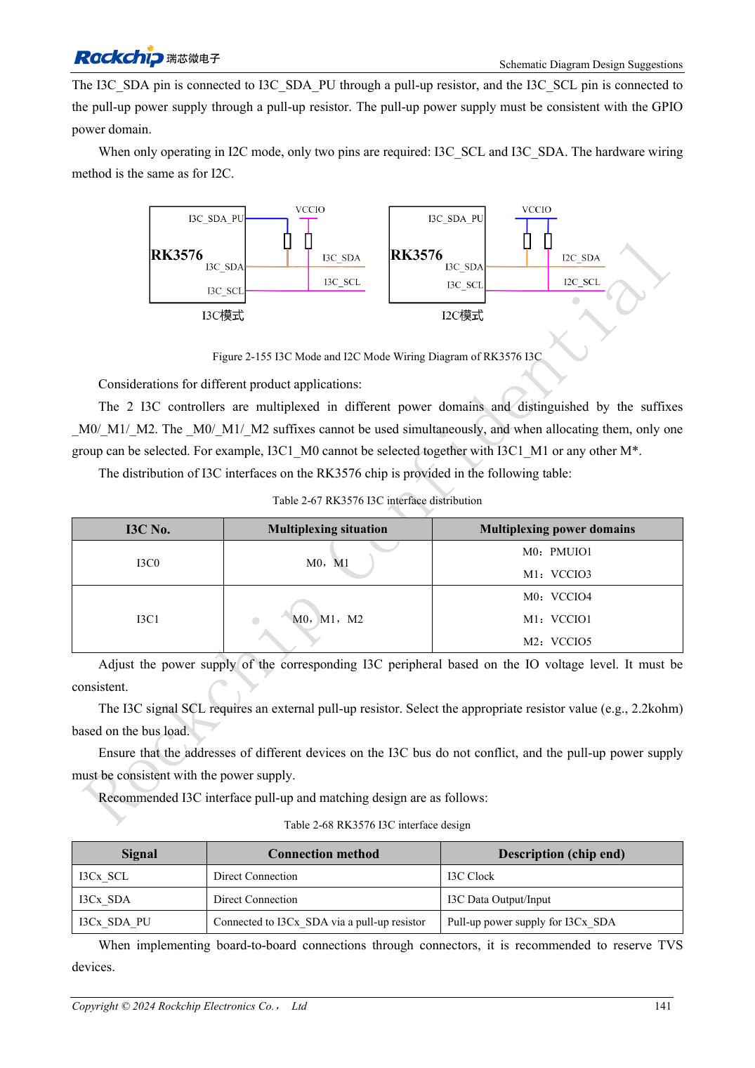
English original · PDF 160 · 2-155
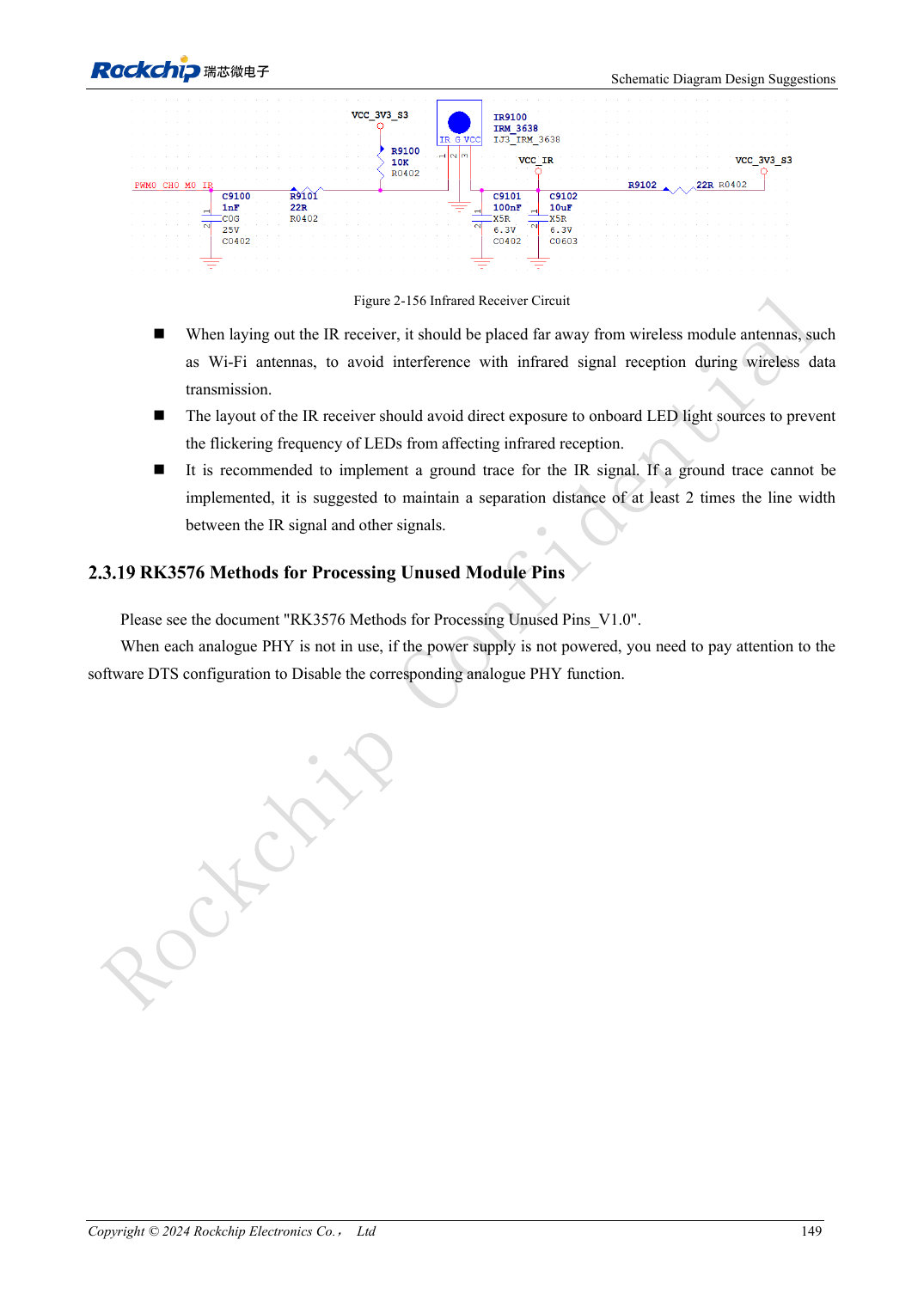
English original · PDF 168 · 2-156
ArmSoM development path
CM5 reduces repeated compute-core design on custom carriers; Sige5 provides a starting point for software and peripheral evaluation. Verify exposed interfaces, connector pins, voltages and image support in board documentation rather than inferring them from SoC features.