
Based on the Chinese and English RK3576 Hardware Design Guide V1.1 (2024-05-28), for SoC-board design. CM5 carriers must follow the module interface; Sige5 can establish a software/peripheral baseline. This guide does not prescribe one SDK/BSP or kernel for every product; verify each board. Values are source references, not ArmSoM measurements.
RK3576_Hardware_Design_Guide_V1.1_20240528_EN.pdf · §2.1.11; §2.3.2
GPIO voltage belongs to the entire domain
PMUIO0 and VCCIO0 are fixed at 1.8V. VCCIO7 uses 1.2V for UFS and otherwise 1.8V per the guide. PMUIO1 and VCCIO1–6 support 1.8/3.3V. Changing one pin’s function does not give other pins in the same domain a different voltage. Suffixes _u/_d/_z denote pull-up, pull-down and high impedance; check boot probing and sleep states too.
Prevent back-power in off and standby states
The guide supports retention with core power off and IO still powered, but not fail-safe inputs when both core and IO are off. A powered peripheral must not drive a high level into an unpowered domain. Review pull-up ownership, enable order and isolation together. Check per-pin drive strength rather than assuming one current capability for every GPIO.
SARADC keys and boot roles
SARADC provides 12bit, up to 1MS/s and eight 0–1.8V inputs. IN0 serves boot configuration; IN1 recovery requires a 10kΩ, 1% pull-up even without a button. Recommended key spacing exceeds 300 counts or 132mV, with nearby 1nF filtering. Reference protection is connector→ESD→100Ω→1nF→chip. Never connect a 3.3V signal directly to the ADC.
Design parameters and review table
| Item | Source reference |
|---|---|
| SARADC | 12bit; 0–1.8V |
| IN1 pull-up | 10kΩ ±1% |
| Key-level separation | >300 counts / >132mV |
| Filter capacitor | 1nF |
Source figures
The reference pages below contain the relevant circuit or timing figures; click for full resolution. Designators and component values belong to the reference design, not an ArmSoM product schematic.
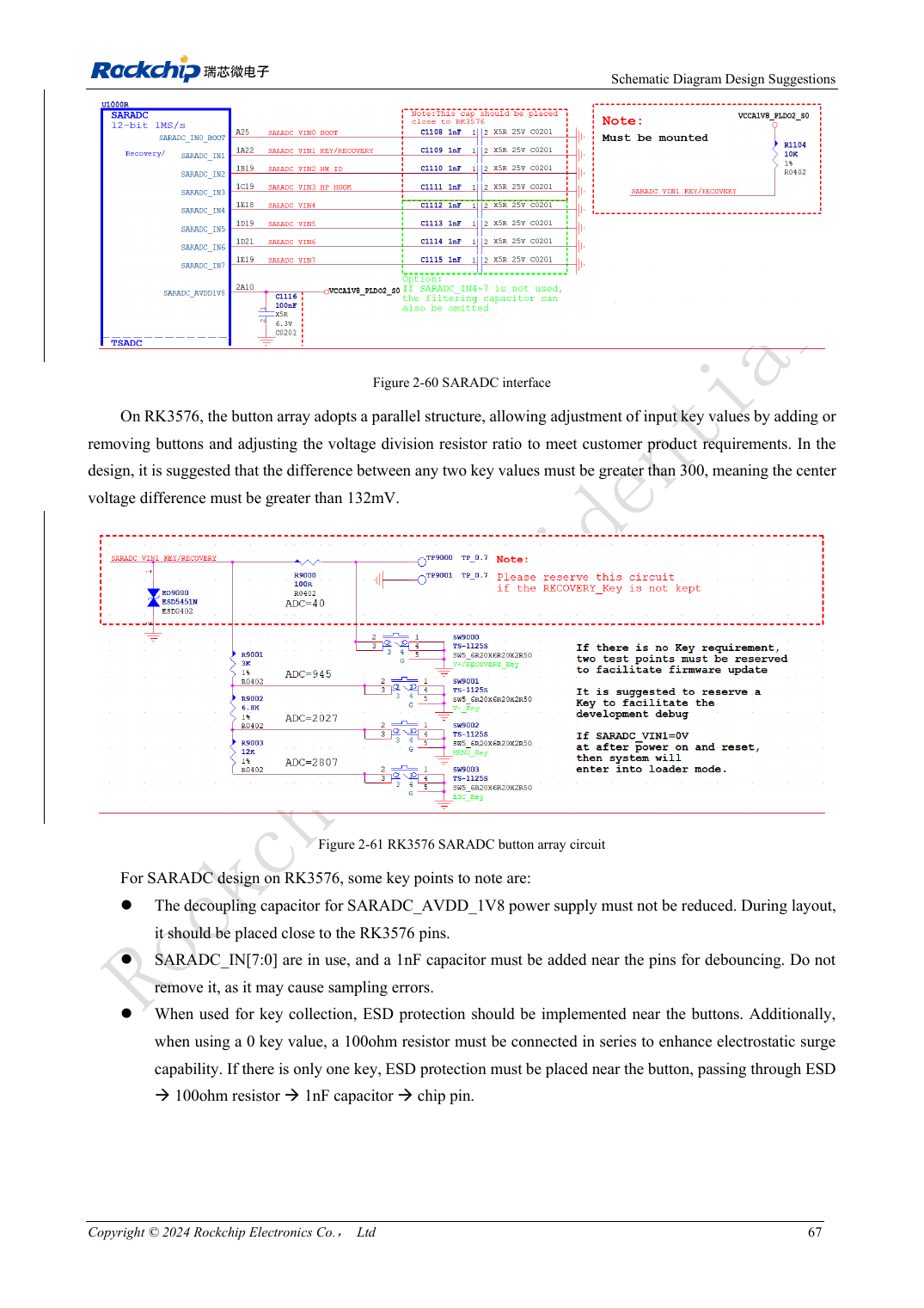
English original · PDF 86 · 2-61
ArmSoM development path
CM5 reduces repeated compute-core design on custom carriers; Sige5 provides a starting point for software and peripheral evaluation. Verify exposed interfaces, connector pins, voltages and image support in board documentation rather than inferring them from SoC features.