
Based on RK3308 Hardware Design Guide V1.0 (2018-09-14), with the 2023 V1.1 compatibility note used to identify variant boundaries. P2 Pro uses RK3308B-S; the historical reference does not replace its board design. This topic article is not a complete page-by-page translation. Source values are not ArmSoM measurements. Check actual interfaces, SDK/BSP, kernel and firmware for the board revision.
RK3308硬件设计指南_V1.0_20180914.pdf · §2.3
Align analog channels with the algorithm
The original RK3308 provides eight ADC and two DAC channels. The six-microphone/two-speaker example uses MIC3–MIC8 for capture and MIC1–MIC2 for loopback. Each of two MICBIAS outputs supplies 3mA; the reference divides six microphones evenly, but actual microphone current still matters. Line Out feeds an external amplifier and must not be treated as a speaker-power output. HP Out PHONE_DET is 1.8V when high. Check P2 Pro schematics for exposed channels and connectors.
Do not double-count I2S and PDM resources
I2S0_2CH, I2S0_8CH and I2S1_8CH are three independent interfaces with master/slave support, up to 192kHz and 16–32bit in the source. I2S1_8CH M0/M1 are mux alternatives, not two interfaces. PDM has one controller and only one of M0/M1/M2 may be selected. Each SDI can carry two microphones; check the microphone’s L/R polarity. For continuous standby voice capture, the guide recommends PDM_8CH_CLK_S_M2 instead of CLK_M_M2, which stops during sleep. A continuous clock does not prove that the SDK implements a complete wake algorithm.
Choose loopback for the amplifier output
A digital amplifier can form an I2S output/return loop. Analog loopback needs attenuation, filtering and DC blocking. Use the source divider scheme when Class D output has LC filtering, or its second-order RC reference without LC. The source requires DC voltage at A/B below 500mV: never connect speaker power output directly to an ADC. The second-order RC reference plus SoC coupling capacitor forms about a 22Hz–22kHz band-pass; verify values for the actual amplifier. Protect microphone openings with local ESD. Record each channel first, checking physical order, polarity and level, then test playback concurrency, echo cancellation and sleep/wake.
Source microphone and loopback allocation
| Application | Microphone input | Loopback |
|---|---|---|
| 6 MIC + 2 Speaker | MIC3–MIC8 | MIC1–MIC2 |
| 6 MIC + 1 Speaker | MIC3–MIC8 | MIC1 |
| 5 MIC + 2 Speaker | MIC4–MIC8 | MIC1–MIC2 |
| 5 MIC + 1 Speaker | MIC4–MIC8 | MIC3 |
| 4 MIC + 2 Speaker | MIC5–MIC8 | MIC3–MIC4 |
| 4 MIC + 1 Speaker | MIC5–MIC8 | MIC3 |
| 3 MIC + 1 Speaker | MIC6–MIC8 | MIC5 |
| 2 MIC + 1 Speaker | MIC7–MIC8 | MIC5 |
Source: table 2-10, PDF33. Preserve the different loopback assignments rather than normalizing everything to MIC1/2. This is a silicon reference, not proof that P2 Pro exposes or validates every combination.
Source figures and review pages
Only Chinese originals are available in this batch. All four languages use the same source images, retaining figure context; image labels are not translated. Prose is editable. Page numbers are physical PDF pages.
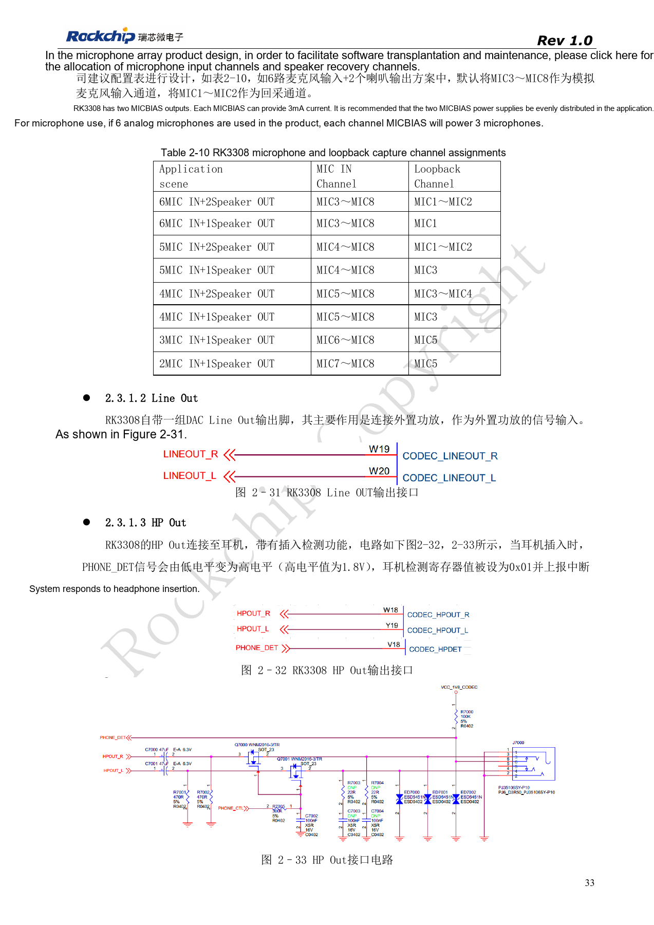
PDF 33
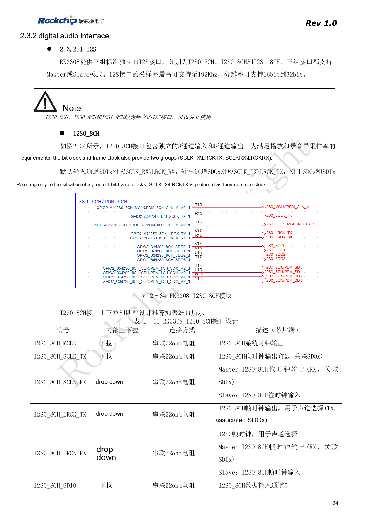
PDF 34
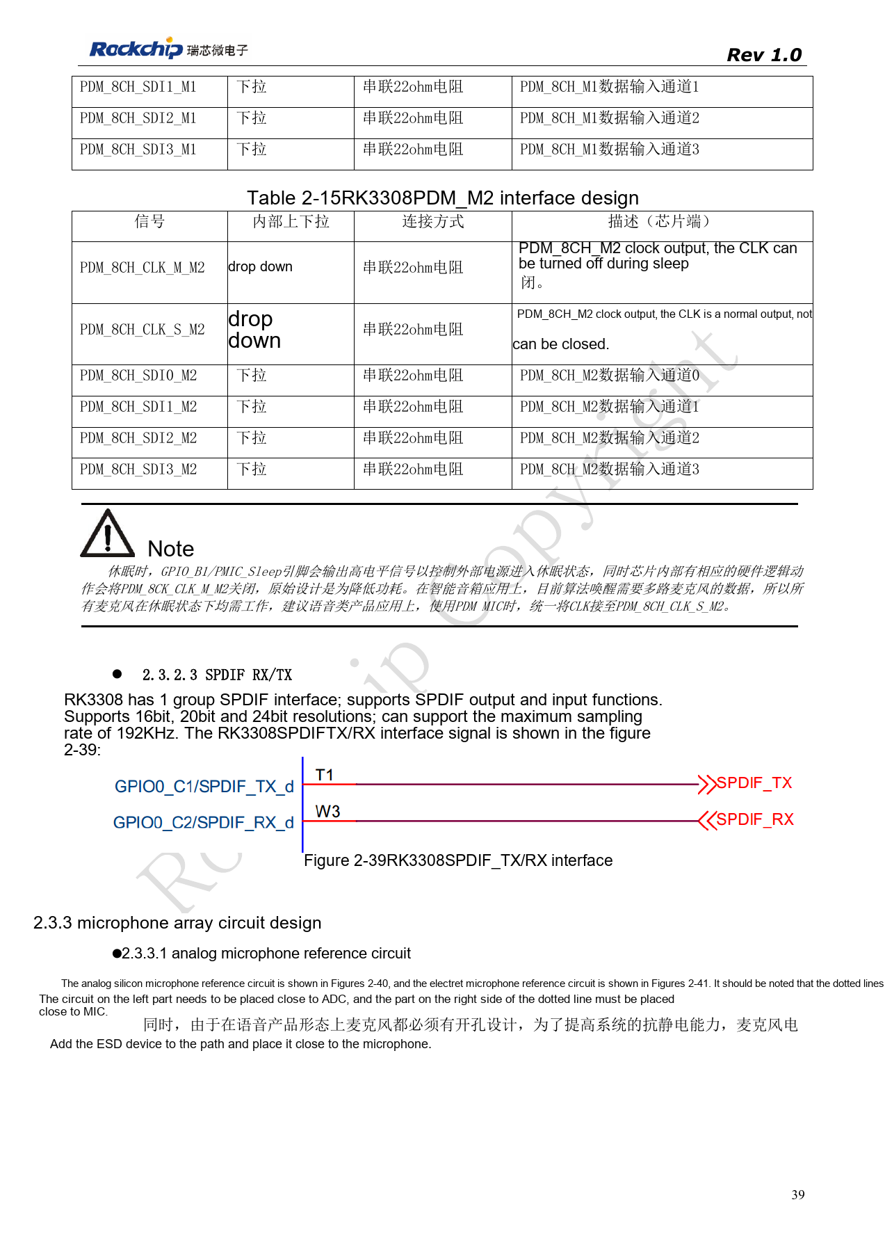
PDF 39
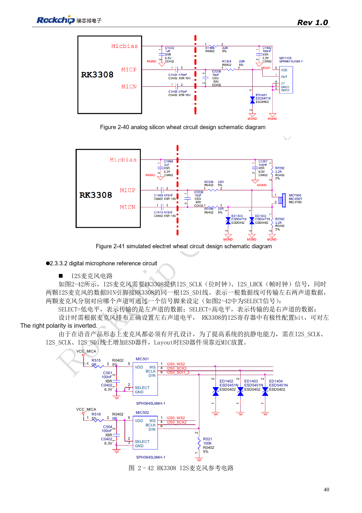
PDF 40
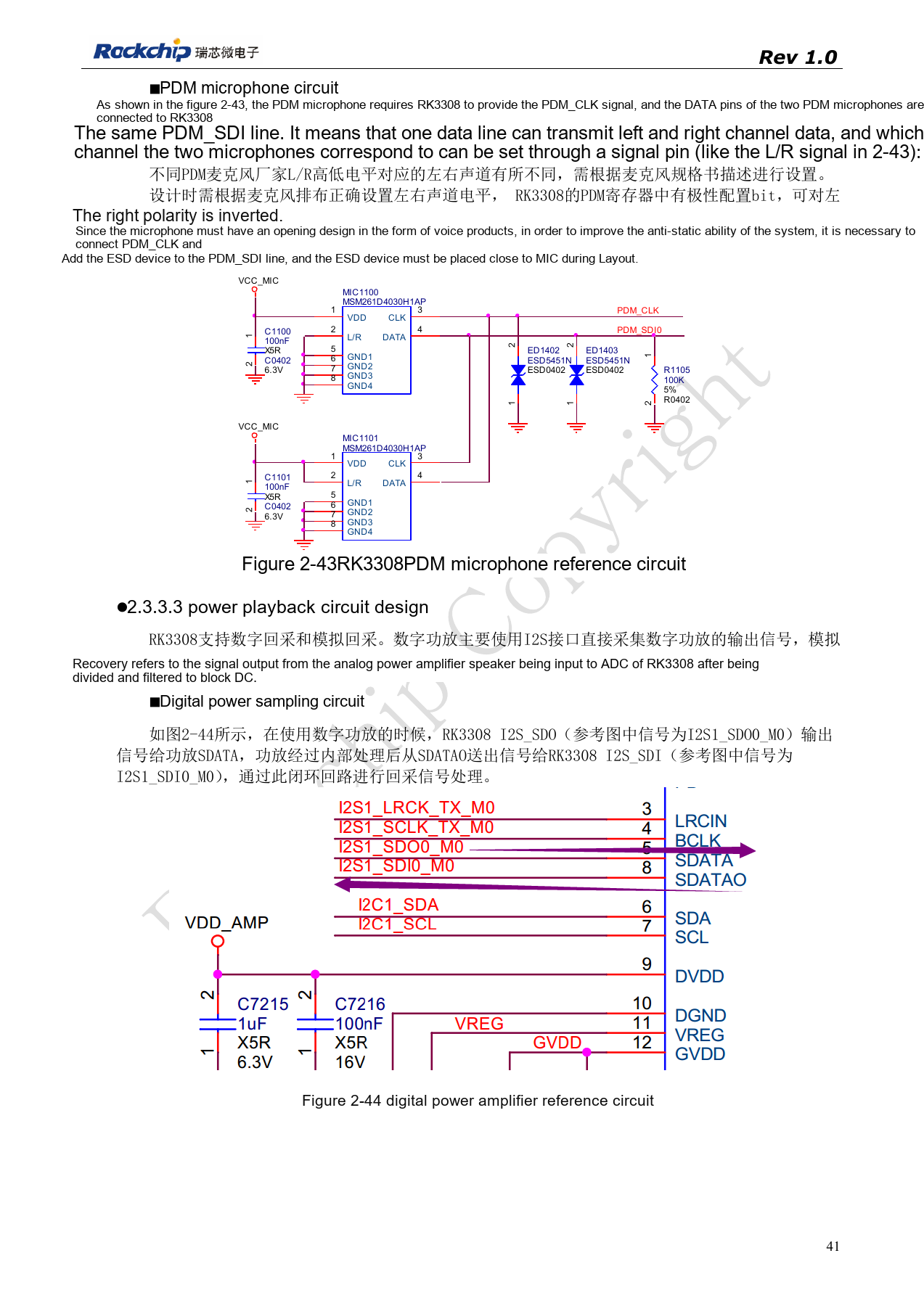
PDF 41
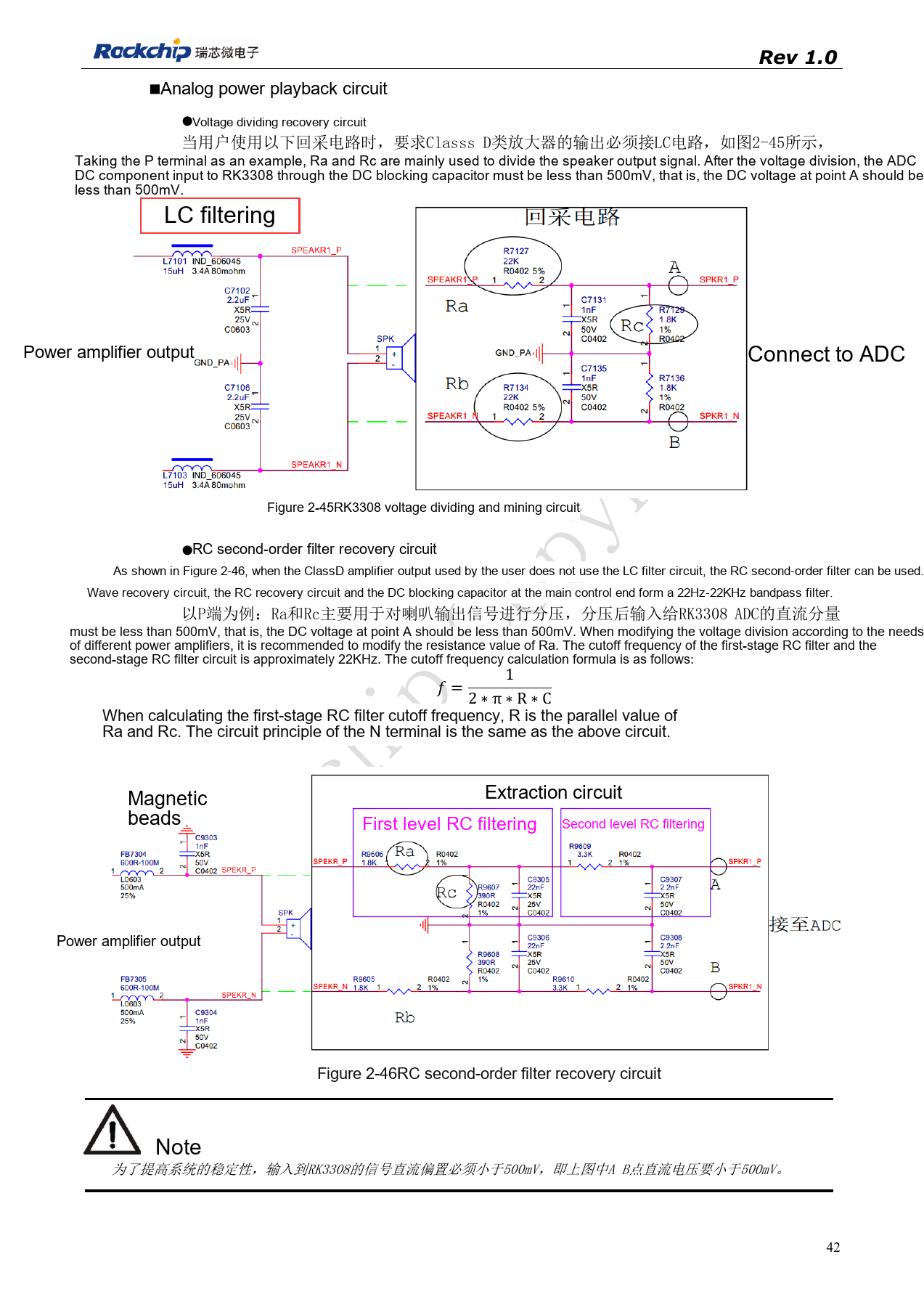
PDF 42