
Based on RK3308 Hardware Design Guide V1.0 (2018-09-14), with the 2023 V1.1 compatibility note used to identify variant boundaries. P2 Pro uses RK3308B-S; the historical reference does not replace its board design. This topic article is not a complete page-by-page translation. Source values are not ArmSoM measurements. Check actual interfaces, SDK/BSP, kernel and firmware for the board revision.
RK3308硬件设计指南_V1.0_20180914.pdf · §2.1; §2.4.1; §2.4.6–2.4.7
Keep the historical scope explicit
The 2018 V1.0 guide describes RK3308/RK3308G, not the complete requirements for the RK3308B-S used by P2 Pro. Its clock reference is 24MHz, ±20ppm and ESR≤40Ω. The 15pF loading is a crystal-specific example. NPOR is active low in the 1.8V domain; the reference grounds NPOR_BYPASS to enable internal reset. It requires the VCC_IO monitored for internal reset to remain at the reference 3.3V, not 3.0V. For S variants, also check the newer compatibility document.
Check boot media and voltage together
The documented boot priority is NAND, eMMC, SPI Flash/SFC, SDMMC, then USB OTG Device. FLASH_SEL is GPIO0_A4 (R3), sampled at power-on: 0 corresponds to VCCIO3=3.3V and 1 to 1.8V. A peripheral must not disturb this level during reset. eMMC is 8bit, 4.5.1 and HS200 without CMD Queue; place 22Ω in CLK while CMD/data connect directly. SFC supports NOR/NAND boot and also uses 22Ω in CLK. Match the flash device to bootloader, DDR initialization and support lists; a matching interface standard alone does not establish support.
SD card versus UART debugging
Default UART2_M1 shares pins with SDMMC. When a TF card is used, reserve UART2_M0 and switch it in software rather than assuming the original debug port remains usable. SARADC_IN1 also serves Recovery: with firmware present, hold it at 0V, no more than 100mV, during startup; release it to 1.8V after the PC detects Rockusb. Preserve the pull-up and use ADC key-code spacing greater than 35. During bring-up identify whether failure occurs in ROM, DDR initialization, storage or the kernel before replacing devices blindly.
Source figures and review pages
Only Chinese originals are available in this batch. All four languages use the same source images, retaining figure context; image labels are not translated. Prose is editable. Page numbers are physical PDF pages.
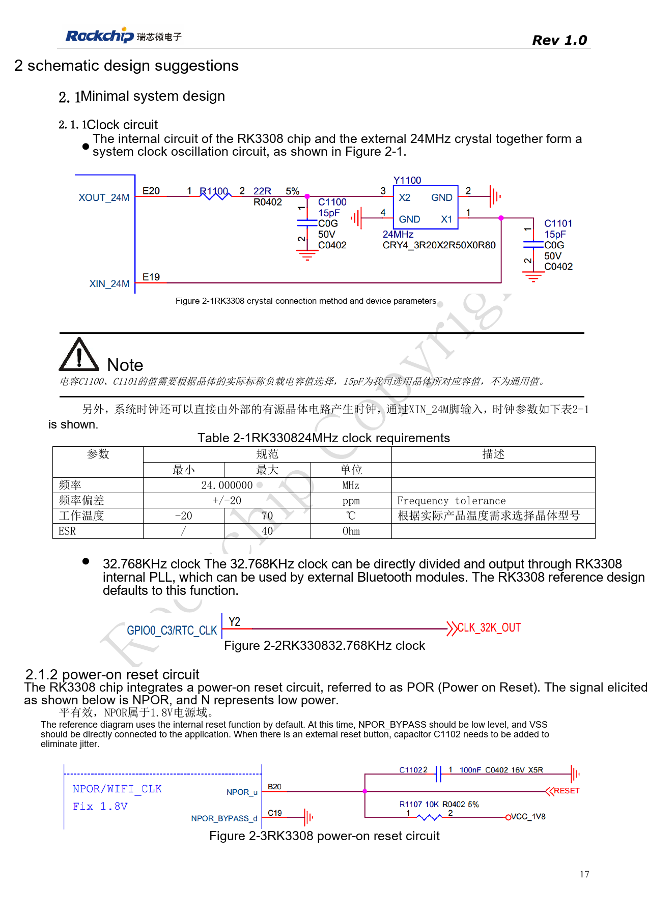
PDF 17
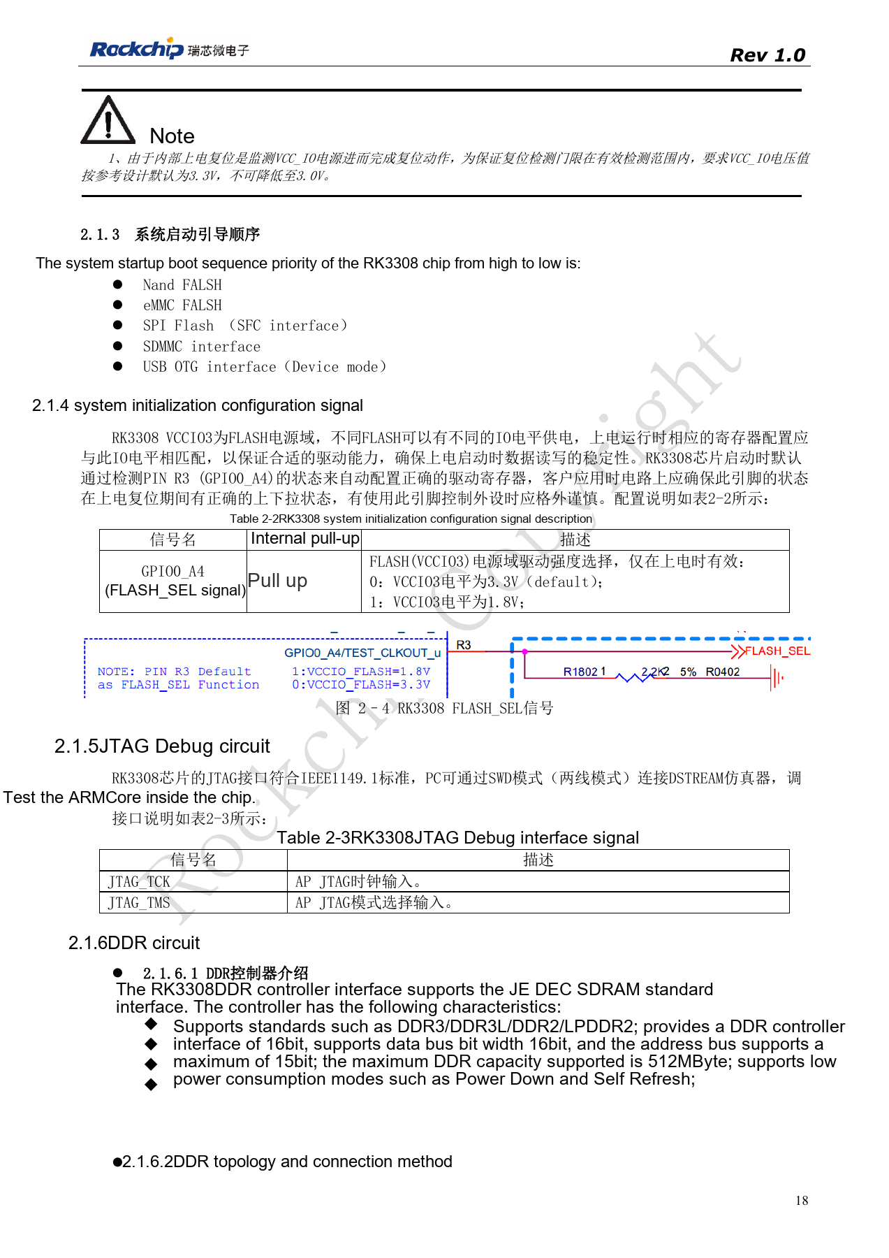
PDF 18
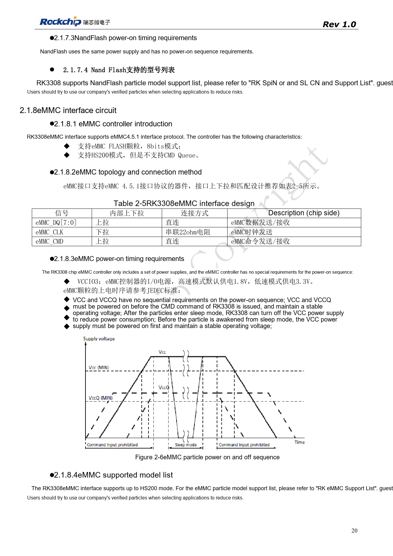
PDF 20
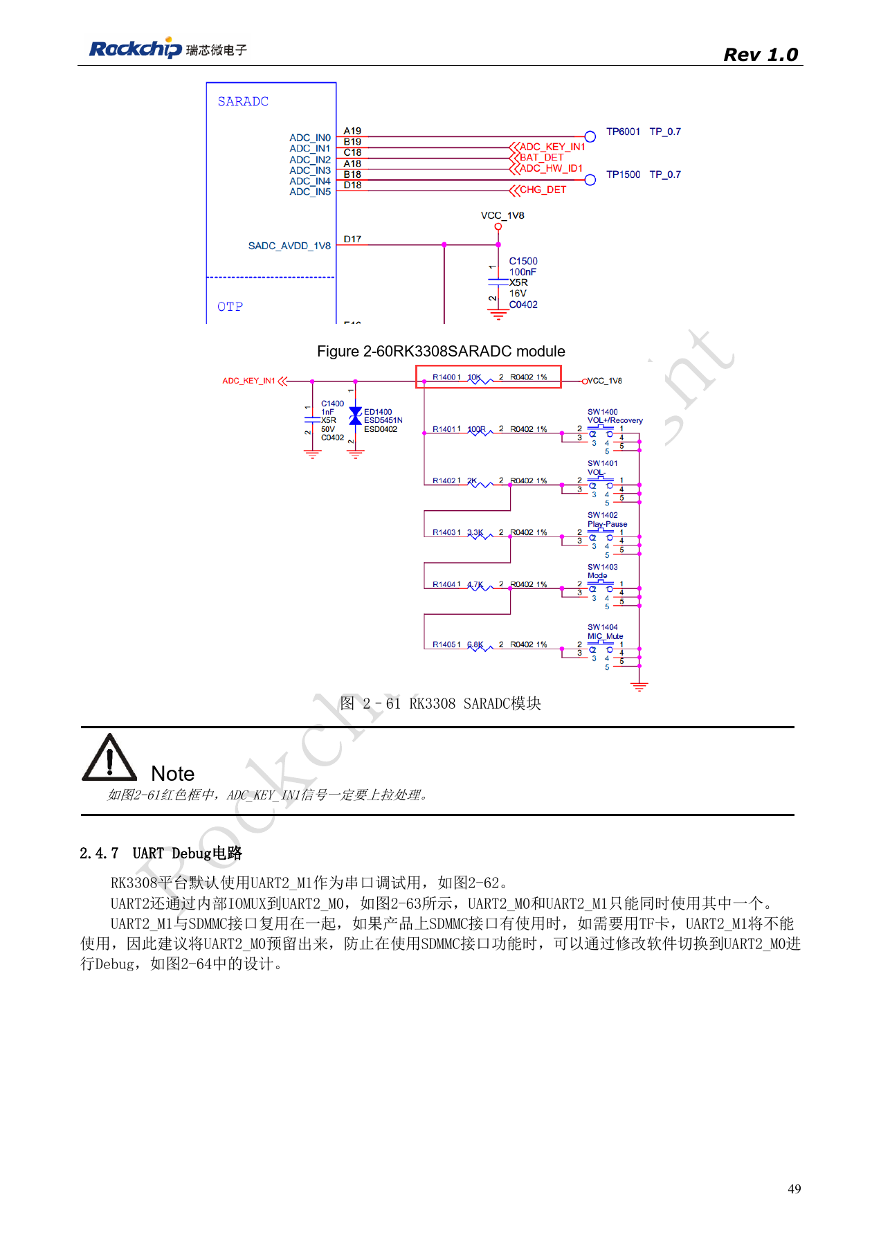
PDF 49
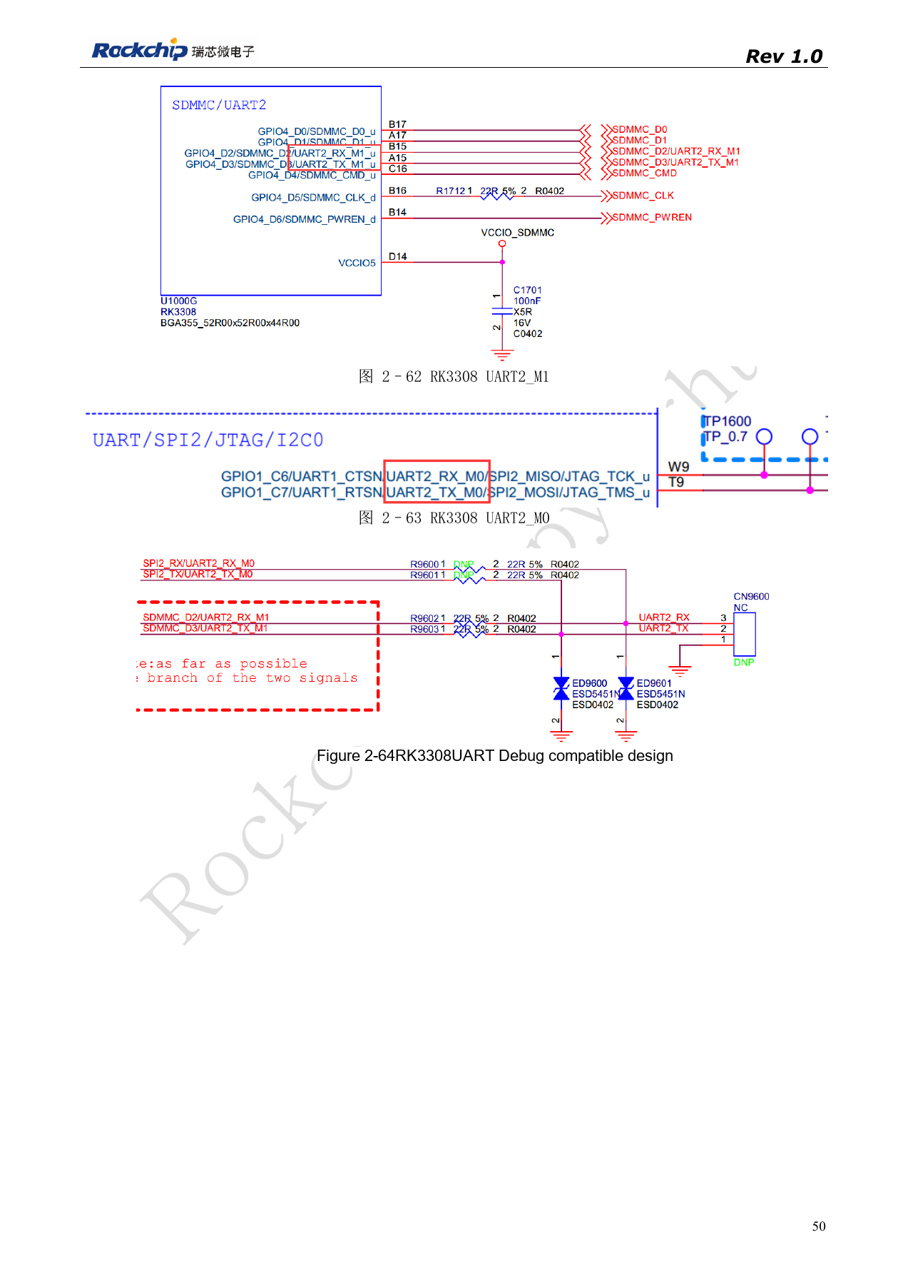
PDF 50