
Based on the Profile Chinese/English RK-KF-YF-301 V1.2.0 (2025-12-13), using Chinese as the technical baseline and comparing ApplicationNote English V1.1.2 (2021-07-30). All technical chapters, protocols, parameters, code and screenshots are retained, with legacy flows distinguished. This ArmSoM platform reference requires checking the actual board, SoC, SDK/BSP and peripherals. No tests, flashing or device commands were executed. The recovery flow uses wipe_all to format userdata; it is not merely a reboot.
Source product table: RK3328, RK3326, RK3358, PX30, RK3229, PX3-SE, RK3399, RK3288 and other Linux platforms; tool V1.7.
1. PCBA Test Tool
1.1 Overview
PCBA test tool is used to help to identify product features during production quickly, or calling key FCT (Functional Test), to improve the production efficiency. PCBA test tool is developed under the Window system and only supports running in Window system. With the device-side test program, it can verify the integrity and quality of the functions or components that need to be focused on. Current test items include: SD card test, Wi-Fi test, Bluetooth test, DDR test, ring MIC test, USB host test, led test, playback test, recording test, button test, PDM MIC test, Audio Line in test, SPDIF IN/OUT test, etc., which can be extended in future. These test items include automatic test items and manual test items, in which SD card test, Wi-Fi test, Bluetooth test, DDR test, ring microphone test, USB host test are automatic test items; led light test, playback test, recording test, button test, PDM MIC test, Audio Line in test, SPDIF IN/OUT test are manual test items. The automatic test items does not require manual intervention. When finishing test, the test result including passed or failed items will be reported directly. The manual test items need to manually judge whether the test item is passed or not and give the result (pass or fail).
1.2 Test Tool Installation
Run the PCBA tool installer PCBATool_Setup_xxxx.exe, when successfully, it will generate an executable program and related configuration files and other programs and library files used in the tool in the specified directory.
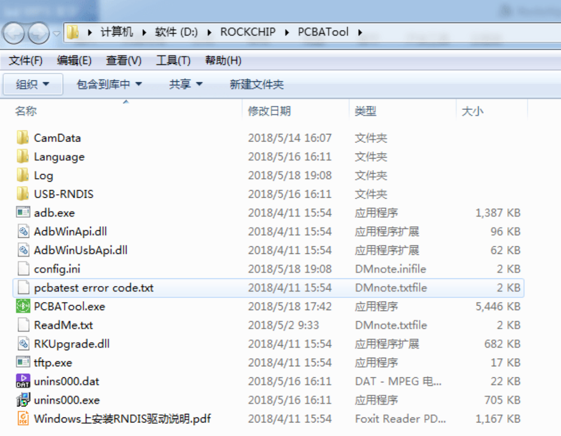
Figure 1-1 PCBA Tool Installation Note: The “CamData” directory is used to store single-frame images captured at specific moments during camera testing. These images are saved in BMP format. Currently unused. The “Language” directory: stores language configuration file of the tool. The “Log” directory: store various log files during the tool test process to facilitate for troubleshooting later. The “Config.ini”: a tool configuration file that records configuration information, language configuration, and other configuration information of the tool. Note: If you specify a custom installation directory, please make sure the path use full English name to avoid the problem of using ADB tool fail with non-English path.
1.3 Test Tool Introduction
Figure 1-2 shows the main interface of the PCBA test tool
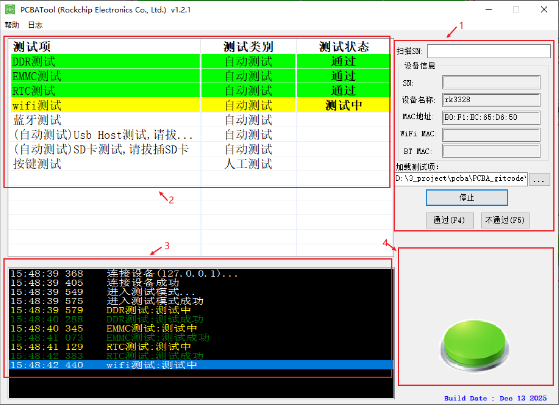
Figure 1-2 PCBA Tool Interface As shown in the above figure, the PCBA Tool mainly included four parts. Part 1 displays device information. After testing begins, it retrieves the device name and MAC address. Pre-configured test settings can be loaded by selecting test items. Below are controls for configuring test items, starting/stopping tests, and manually determining pass/fail outcomes. Part 2 shows a list view of test items, displaying test categories and results. Part 3 is the information display list box for each test item’s process, showing the test progress and results. Part 4 displays the device connection status and test pass results. If the tool detects the device is available (recognized as an ADB device), a green button icon is shown; otherwise, an orange button icon is displayed. Test results will appear in this area upon completion.
1.4 Test Items Configuration
Clicking the “…” button on the main tool interface to load test items or pressing the F2 shortcut key will open the configuration item loading dialog box, as shown in Figure 1-3. Select the required JSON file for the configuration item and click the Open button. The selected item will then appear in the test item list box described in Part 3 above, displaying the specific test type based on the defined test type (automated or manual) for each test item. An example JSON file is shown in Figure 1-4.
{
    "meta": {
        "version": "1.0",
        "author": "rockchip_dep3",
    "description": "PCBA Motherboard Functional Testing Configuration",
    "needreboot": true
},

"test_groups": [
    {
        "test_item": "ddr_test",
        "test_bin_name": "echo_ddr_test",
        "name": "DDR Test",
        "test_type": "auto",
        "description": "",
        "enable": 0,
        "is_loop_test":false,
        "is_first": false,
        "is_last": false,
        "is_check_sn": false
    },

    {
        "test_item": "emmc_test",
        "test_bin_name": "echo_emmc_test",
        "name": "EMMC Test",
        "description":"",
        "test_type": "auto",
        "enable": 0,
        "is_loop_test":false,
        "is_first": false,
        "is_last": false,
        "is_check_sn": false
    },

    {
        "test_item": "rtc_test",
        "test_bin_name": "echo_rtc_test",
        "name": "RTC Test",
        "description":"",
        "test_type": "auto",
        "enable": 0,
        "is_loop_test":false,
        "is_first": false,
        "is_last": false,
        "is_check_sn": false
    },

    {
        "test_item": "wifi_test",
        "test_bin_name": "echo_wlan_test",
        "name": "WIFI Test",
        "description":"",
        "test_type": "auto",
        "enable": 0,
        "is_loop_test":false,
        "is_first": false,
        "is_last": false,
        "is_check_sn": false
    },
{
    "test_item": "bt_test",
    "test_bin_name": "echo_bt_test",
    "name": "BT Test",
    "description":"",
    "test_type": "auto",
    "enable": 0,
    "is_loop_test":false,
    "is_first": false,
    "is_last": false,
    "is_check_sn": false
},

{
    "test_item": "camera_test",
    "test_bin_name": "echo_camera_test",
    "name": "Camera Test",
    "description":"",
    "test_type": "auto",
    "enable": 0,
    "is_loop_test":false,
    "is_first": false,
    "is_last": false,
    "is_check_sn": false
},

{
    "test_item": "usbhost_test",
    "test_bin_name": "echo_usbhost_test",
    "name": "U-disk Test",
    "description":"",
    "test_type": "auto",
    "enable": 0,
    "is_loop_test":false,
    "is_first": false,
    "is_last": false,
    "is_check_sn": false
},

{
    "test_item": "sdcard_test",
    "test_bin_name": "echo_sdcard_test",
    "name": "SD-card Test",
    "description":"",
    "test_type": "auto",
    "enable": 0,
    "is_loop_test":false,
    "is_first": false,
    "is_last": false,
    "is_check_sn": false
},

{
    "test_item": "audio_play_test",
    "test_bin_name": "echo_audio_play_test",
            "name": "Audio Playback Test",
            "description":"",
            "test_type": "manual",
            "enable": 0,
            "is_loop_test":false,
            "is_first": false,
            "is_last": false,
            "is_check_sn": false
        },

        {
            "test_item": "audio_record_test",
            "test_bin_name": "echo_audio_record_test",
            "name": "Recording Playback Test",
            "description":"",
            "test_type": "manual",
            "enable": 0,
            "is_loop_test":false,
            "is_first": false,
            "is_last": false,
            "is_check_sn": false
        },

        {
            "test_item": "key_test",
            "test_bin_name": "echo_key_test",
            "name": "Key Test",
            "description":"",
            "test_type": "manual",
            "enable": 1,
            "is_loop_test":false,
            "is_first": false,
            "is_last": false,
            "is_check_sn": false
        },
    },

    "mes_config": {
        "use_mes": false,
        "product":"RM1820SA0",
        "station":"FT1",
        "station_ip":"10.58.9.21",
        "note": "url_path1 use for actual production",
        "url_path1":
"http://rjiot.ruijie.com.cn/api/services/app/RuiJieATE/EquipmentUniversalPort",
        "note2": "url_path2 just use for test, don't use for production",
        "url_path2":
"http://10.60.5.223:8080/api/services/app/RuiJieATE/EquipmentUniversalPPort",
        "is_test": true,
        "ftp_server":"10.60.5.224",
        "ftp_port":"21",
        "username":"",
        "password":""

    }
}
The following is an example JSON file, divided into three sections: meta: Basic attributes. The version field contains version information; author contains author information; description contains a detailed description of the test; needreboot indicates whether a reboot is required after the test completes. test_group: Test item attributes. test_item identifies the test item for program recognition; test_bin_name specifies the executable program name running on the test board, paired with the PC tool application to execute the test; name is the test item name; description provides a detailed description of the test item; test_type indicates the test item type, currently manual or auto . manual denotes a manual test item requiring manual pass/fail determination via the test tool’s main interface button, while auto denotes an automated test item where the test tool automatically determines and displays the pass/fail status; is_loop_test , is_first , is_last , is_check_sn are customizable test item fields. Set to false for non-use. mes_config: MES server settings. Customizable test item field for uploading test results to the cloud. Set use_mes to false for non-use. Modify as needed for custom development. Currently supported public configuration items include: SD card test, button test, Wi-Fi test, Bluetooth test, audio playback test, audio recording test, USB host test, RTC test, camera test, etc. Additional public tests will be added in future updates. Configuration items supported for the RK3308 platform include: SD card testing, Wi-Fi testing, Bluetooth testing, DDR testing, microphone loopback testing, USB host testing, LED testing, audio playback testing, audio recording testing, button testing, PDM mic testing, audio line-in testing, SPDIF IN/OUT testing, etc. Additional extended test items may be added in the future. Chips on other Rockchip platforms can be configured with corresponding test items based on requirements and hardware development board availability.
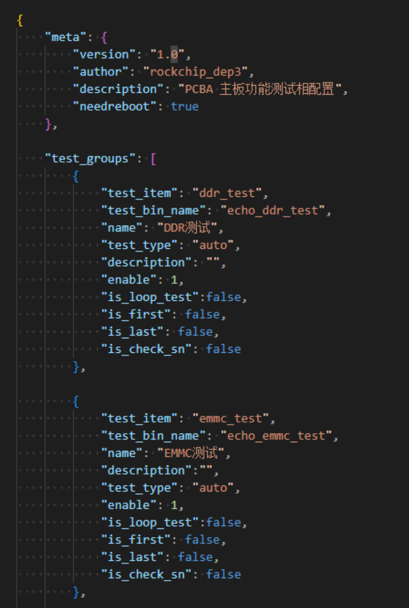
Figure 1-3 PCBA Test Items Configuration Dialog
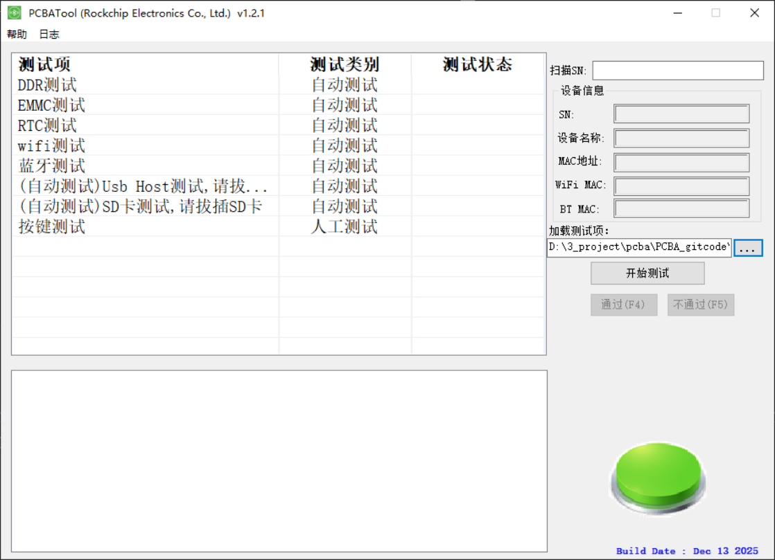
Figure 1-4 PCBA Configuration is Completed
1.4.1 Test Items Introduction
-
WiFi Test: An automated test item. During WiFi testing, the device automatically scans nearby WiFi hotspots and determines success based on the scan results.
-
Bluetooth Test: An automated test item. On older platforms, Bluetooth testing involved the device first automatically disabling Bluetooth devices, then re-enabling Bluetooth and activating it after loading the firmware. On newer platforms, this disabling and re-enabling step is omitted (the firmware loads automatically at startup). Success is then determined by whether the Bluetooth control interface hci0 is successfully enabled and whether a Bluetooth hardware address is present.
-
DDR Test: Automatic test item. When testing DDR, the device’s DDR capacity is automatically read. Success is determined by whether the reading is correct.
-
EMMC Test: An automated test item. When testing EMMC, the device’s EMMC capacity is automatically read. Success is determined based on whether the reading is correct.
-
RTC Test: An automated test item. When testing RTC, the system time is set to a fixed value. The process is put into sleep for a fixed duration. Upon wake-up, the time is read to check if the time difference matches the fixed value. If consistent, the test succeeds; otherwise, it fails.
-
SD Card Test: An automated test item. When testing the SD card, a test script runs. An SD card is inserted, and the test checks whether the device node exists. If present, the SD card is automatically mounted to a specified file directory, and its capacity is recorded. If no device node is detected within 60 seconds, an error is reported and the test exits automatically.
-
USB Host Test: An automated test item. When testing USB Host functionality, a test script runs. Insert the USB host device and check if the test device node exists. If present, the host device is automatically mounted to the specified file directory, and the device capacity is recorded. If no device node is detected within 60 seconds, an error is automatically reported and the test exits.
-
CAMERA Test: An automated test item. During the CAMERA test, the v4l2_capture.sh test script runs to obtain available camera devices for photo capture, prioritizing saving in JPG format. Success is determined by using photo_check.sh to verify the correctness of the saved photo format.
-
LED Test: Manual test item. During LED testing, the device displays red lights in the first round, green lights in the second round, blue lights in the third round, and a white light (combining all three colors) in the fourth round. Manual intervention is required to determine test success or failure based on whether each light illuminates correctly. Click the Pass or Fail button to proceed to the next test item.
-
Audio Playback Test: Manual test item. During audio playback testing, the device plays audio data stored in a designated location. Manually determine test success or failure based on audio quality. Click the Pass or Fail button to proceed to the next test.
-
Recording Test: Manual test item. When testing the recording function, the device will continuously record a segment of audio captured by the current microphone and then play back the recorded sound through the device. The tester must determine test success or failure based on the played-back sound quality. Click the Pass or Fail button to proceed to the next test.
-
Key Test: Manual test item. When testing keys, the tester must physically press the keys. If the device detects a key press, the tool will indicate that a specific key has been pressed. If all board-level defined testable keys have been pressed, the tool will display a pop-up notification. Passing this notification indicates test success; otherwise, the test fails. Test results require manual judgment. Click the Pass or Fail button to proceed to the next test item.
-
PDM Mic Test: Manual test item to verify PDM Mic functionality. Operators must determine test success or failure based on the played audio. Click the Pass or Fail button to proceed to the next test.
-
Audio Line In Test: Manual test item. After inserting an audio line-in device at the board level, music is played. The tester must determine test success or failure based on the sound output from the speaker. Click the Pass or Fail button to proceed to the next test item.
-
SPDIF IN/OUT test: a manual test item.
1.4.2 Test Process Introduction
Step 1: After correctly installing the PCBA testing tool, launch the tool. If a green button icon appears in the bottom-right corner, it indicates the tool has successfully scanned the ADB device connected to the PC. If the device connection fails, an orange button icon will appear in the bottom-right corner, indicating the device is currently unavailable. Step2: Click the [… ] button next to [Load Test Items] on the main interface or press the F2 shortcut key. This will open the configuration item loading dialog. Select the required JSON file for the configuration items, then click the [Open] button. The test list box in the main tool window will display the upcoming test items.
Step 3: After clicking the [Start Testing] button, all automated test items and the first manual test item will be tested simultaneously. Automated test items do not require clicking [Pass] or [Fail]. As shown in Figures 1-5 below.
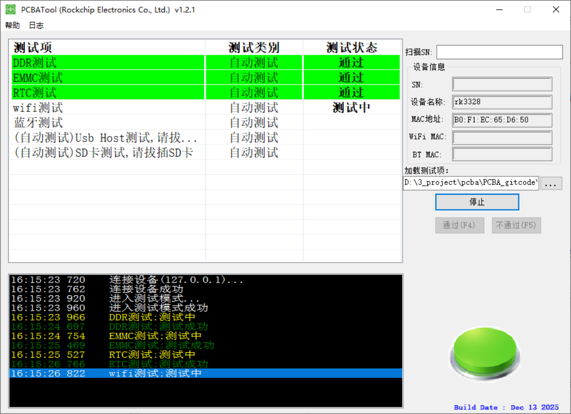
Figure 1-5 PCBA Start Testing Step4: manual test items are single item test. After each test is completed, you have to click [pass] or [not pass] to finish the current test item, and then enter the next test item. Except button test, in which the detailed button name will be displayed in the information prompt window (need to be specified by the program of device). After the test is completed, a window will prompt, and other test items need to be manually judged to pass or not.
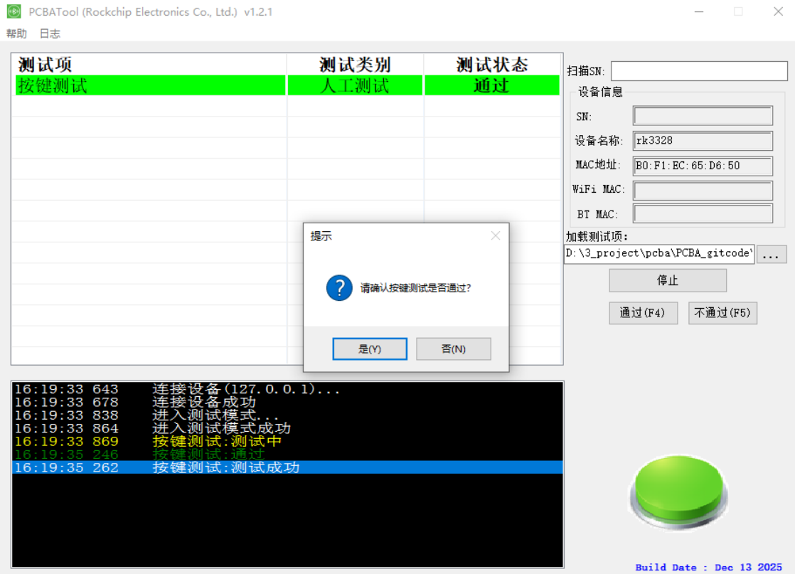
Figure 1-6 PCBA Button Test
1.4.3 Camera Test Item (legacy English section; removed from Chinese V1.2.0)
Camera test is a special item, so it will be introduced in details here. Due to platform differences, camera testing is supported differently depending on platforms. The PCBA test tool has already judged this item according to platform situation. If the current platform does not support the camera test item, the “Camera Test” button on the right side of the tool interface will be grayed and invalid. This section can be skipped; if supported, the button will display normally.

The Dev_Plateform variable in the Config.ini file provides the platform definition. If the variable is not assigned, the “camera test” button will be displayed normally, but pressing the button may result in an error due to unsupported platform, and the function is not available. It is going to describe related bin programs are used in the Camera test: V4l2_test: used to capture a frame of data from the camera stream and write to a file. The related source code is in the ./external/rk_pcba_test/camera_api directory. nv12_to_bmp_main: it is used to convert the nv12 data format file saved by V4l2_test bin program into bmp format for PCBA tool display on PC. It needs to co-work with the libyuv.a static library. The related source code is in ./external/libyuv .
1.4.4 Reboot Items
The configuration file contains meta-type settings, where the needreboot option controls whether a reboot is required.
"meta": {
    "version": "1.0",
    "author": "rockchip_dep3",
    "description": "PCBA Motherboard Functional Testing Configuration",
    "needreboot": true
},
Double rootfs system, such as A/B system, system_a is used to update pcba_rootfs.img, system_b is used to update normal system img firmware by default. When this option is selected, if all configured test items are passed, it will reboot into the normal system. In contrast, other single- system platforms still enter the rootfs file system for PCBA testing after rebooting.
1.5 Further Development Guide
It is easier that if the PCBA test tool needs to do further development to expand test items: you only need to add your own test items on the PCBA test tool according to the following steps.
1.5.1 Development Process Introduction
Install the software development environment VS2022 (select the default C++ desktop development option, and ensure the C++ MFC tool under v143 build tools is checked), as shown in Figure 1-8.
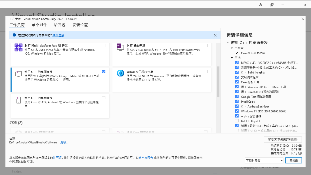
Figure 1-8 PCBA Desktop Application Tool Development Environment Open the source code project, add a new test item in the IDD_SETTING_DIALOG dialog in the resource views, add a CheckBox control and rename the ID and caption.
Add a test item string variable and whether select a Boolean variable to the SettingBase.h header file. Defined in the CIniSettingBase class:
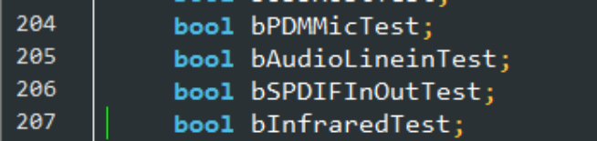

Figure 1-8 Add a Test Item String Variable and Whether Select a Boolean Variable The initialization assignment of these two variables is added to the LoadToolSetting interface in the SettingBase.cpp source code file. Please refer to the assignment of other test item variables.


Figure 1-9 Initialization Assignment of Variables Add the test item name and whether it is configured by default in the Config.ini file. Take the SD card test item as an example, as shown in Figure 1-8. SdcardName is the variable name of the SD card test item, echo_sdcard_test is the name of the bin program running on the board. The SdcardTest variable indicates the default selection state, 0 means not selected by default, and 1 means selected by default. The values of these two variables will be parsed in the code.

Figure 1-10 PCBA config.ini Variable The Chinese and English characters of the corresponding test items are added to the language configuration file Chinese.ini /English.ini to display in the software interface. Also take the SD card test item as an example: Add Chinese display to the test item according to the ID number of the newly added test item. [DIALOG_129]: 129 indicates the IDD_SETTING_DIALOG dialog resource ID. BUTTON_1010: 1010 indicates the resource ID of the SD card test item, the content after the equal sign is going to display the name “SD card” on the software interface. Note:
The resource ID can be found in the VS project: open resource.h to obtain the ID number of a specific dialog box or check box. The echo_sdcard_test is consistent with the value of the SdcardName variable in config.ini . The content after the equal sign is the string displayed on test item list box of the software interface.
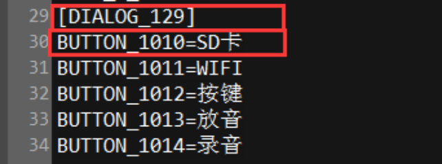

Figure 1-11 PCBA Chinese.ini Variable PcbaTest.cpp source file and PcbaTest.h : add test interfaces for new test items.

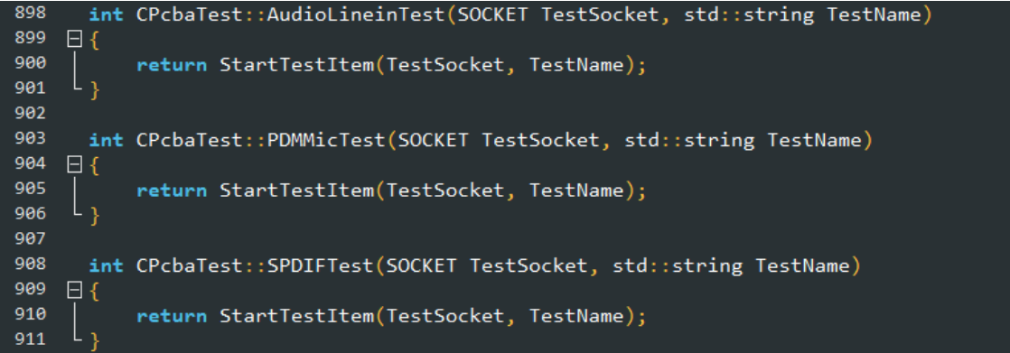
Figure 1-12 Add Test Interfaces for the New Test Item IPSearchDlg.cpp source code file: The initTestCase interface adds the code to select the new test item, please refer to other test item codes. For example:
if (m_Configs.bCpuTest) {
TestCase.TestName = m_Configs.strCpuTest;
TestCase.bAuto = true;
TestCase.bTestLoop = true;
TestCase.nTestStatus = TEST_UNDO;
m_TestCaseList.push_back(TestCase);
}
The DoTestItem Interface adds the code to select and execute the new test item code, please refer to other test item code. For example:
else if (strTestName.compare(m_Configs.strCpuTest) == 0)
{
 ret = m_DevTest.CpuTest(m_TestSocket, wstr2str(strTestName));
}
Note: The TestCase structure is defined as shown below:

Figure 1-13 Detailed Definition of Test Item Structure In the source code of ConfigDlg.cpp : Add the selected status of getting test item check box in BOOL CConfigDlg::OnInitDialog() . For example:
((CButton*)GetDlgItem(IDC_CHECK_CPU))->SetCheck(m_Configs.bCpuTest  ?BST_CHECKED:
BST_UNCHECKED);
Add the setup code for the test item’s default selection state in the Void CConfigDlg::OnBnClickedBtnOk() . For example:
m_Configs.bCpuTest       = (((CButton*)GetDlgItem(IDC_CHECK_CPU))->GetCheck() ==
BST_CHECKED);
At this point, the new test items are finished after compiling without error. Run the tool, breakpoint debugging and trace under DEBUG mode to quickly locate whether the new test item code is running normally.
1.5.2 Package and Release the Tool
Install Inno Setup Inno Setup is a free executable software under windows that is small and simple. Software download address: inno setup download address. PCBATool_package
PCBATool_package is the directory where the package tools are stored. The PCBA executable program and the ini configuration file to be released after successful compilation, the supported language configuration files, and the tool dynamic library dll used by the tool are stored in this directory. Open pcbatool_setup.iss which is the configuration file of Inno Setup. After modifying the necessary APP information, execute “Run” (F9 shortcut key). After running correctly, it will generate packaged installation files in the same level output directory of PCBATool_package directory. And it will run the installation process at the same time, if no need to install, click the cancel button; if needed, execute the installation process.
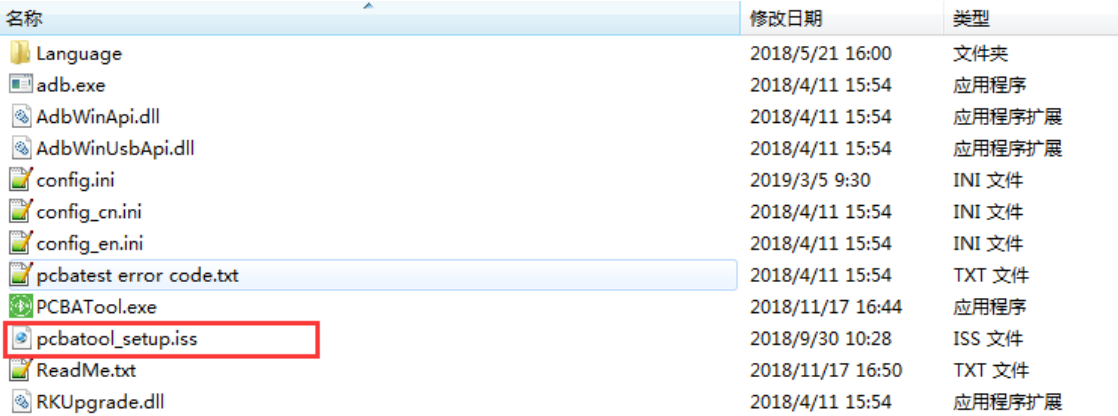
Figure 1-14 List of PCBATool_package Directory
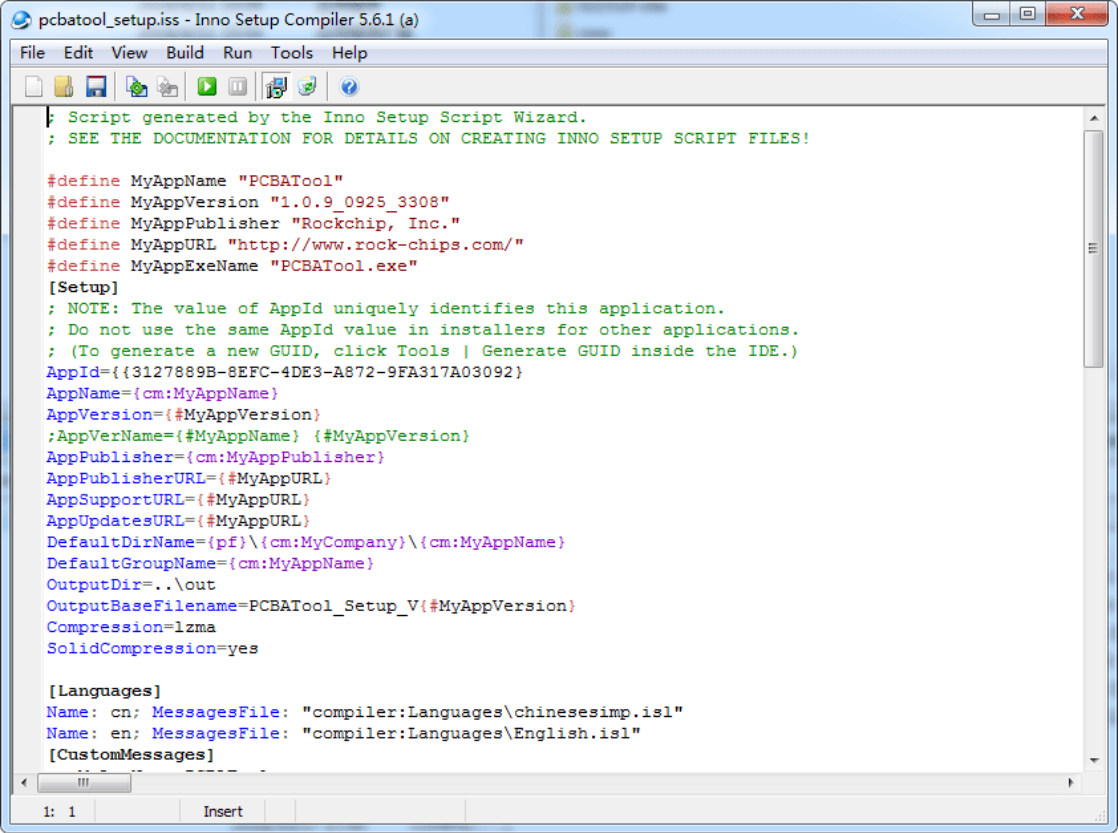
Figure 1-15 Details of Info Setup Compiler Edit the Packable Tool
1.6 Source Code Obtaining
If you need to further develop the PCBA test tool, the source code can be obtained from our FAE. Source code address:
git clone ssh://10.10.10.29:29418/linux/rk_pcba_tool
2. PCBA Software Design Guide
2.1 Design Block Diagram
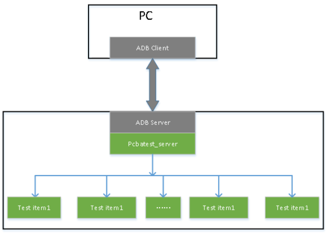
Figure 2-1 Variables of PCBA Design Block Diagram
-
The test tool communicate with the device through ADB protocol.
-
Each test program is an independent process and does not affect each other.
2.2 Design Process
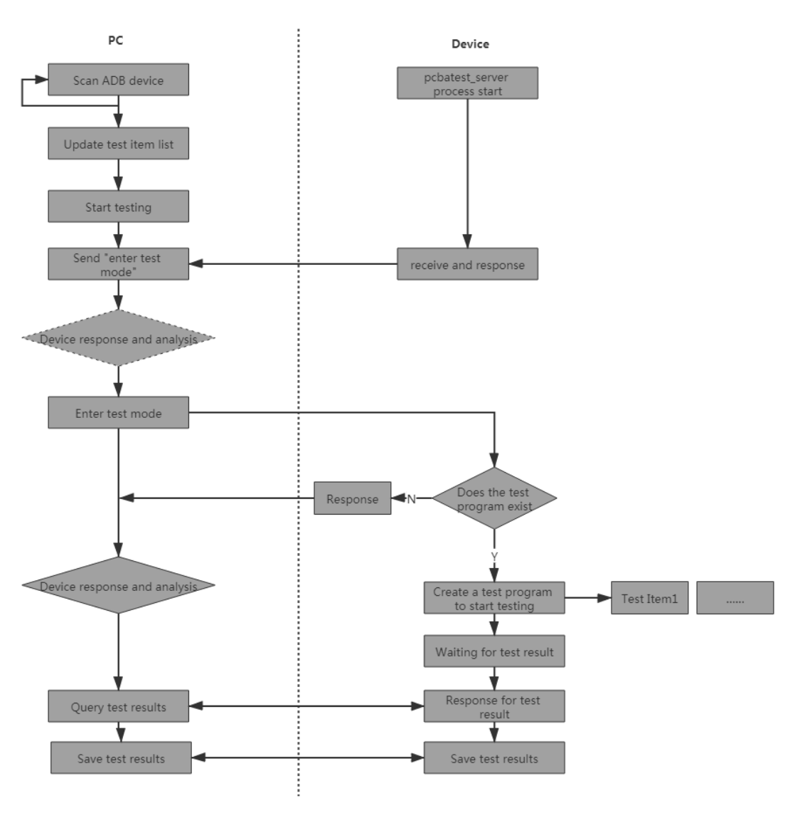
Figure 2-2 Variables in the PCBA Test Flow Diagram
2.3 PCBA Command and Protocol Format
PC and device communicate through a socket over ADB. Command:
Command:<TYPE><TEST_ITEM><CMD><MSG>
Response:<TYPE><TEST_ITEM><RES><MSG><STATUS><RESULT><ERR_CODE>
2-1 Command
| Field/value | Meaning |
|---|---|
TYPE |
Type (source header spells TPYE) |
TEST_ITEM |
Test name |
CMD |
Execution command |
MSG |
Additional data |
2-2 Response
| Field/value | Meaning |
|---|---|
TYPE |
Type (source header spells TPYE) |
TEST_ITEM |
Test name |
RES |
Response command |
MSG |
Additional data |
STATUS |
Status |
RESULT |
Test result |
ERR_CODE |
Error code |
2-3 TYPE
| Field/value | Meaning |
|---|---|
CMD |
PC sends command to device |
RES |
Device responds to PC |
2-4 TEST_ITEM
| Field/value | Meaning |
|---|---|
KEY_test |
Specific test; name must match its executable; extensible |
SDCard_test |
Specific test; name must match its executable; extensible |
AUDIO_test |
Specific test; name must match its executable; extensible |
HDMI_test |
Specific test; name must match its executable; extensible |
CAMERA_test |
Specific test; name must match its executable; extensible |
USB_HOST_test |
Specific test; name must match its executable; extensible |
LED_test |
Specific test; name must match its executable; extensible |
... |
Specific test; name must match its executable; extensible |
2-5 CMD/RES
| Field/value | Meaning |
|---|---|
ENTER |
Enter test mode, without test item |
EXIT |
Exit test mode, without test item |
START |
Start test |
SAVE |
Save test result |
QUERY |
Query test status |
2-6 MSG
| Field/value | Meaning |
|---|---|
msg |
Data sent in command or returned in response; omit if absent |
2-7 STATUS
| Field/value | Meaning |
|---|---|
ACK |
Successful response; device must answer every PC command |
NAK |
Failed response |
2-8 RESULT
| Field/value | Meaning |
|---|---|
TESTING |
Testing |
PASS |
Passed |
FAIL |
Failed |
VERIFY |
Test complete; result confirmation |
PRESS |
Button test only: key pressed |
2-9 ERR_CODE
| Field/value | Meaning |
|---|---|
err_code |
Failure reason; 0x01–0xFF; omitted on success |
-
Enter pcba test mode Enter test mode:{“TYPE”:”CMD”, “CMD”:”ENTER”} Enter test mode response: Correct: {“TYPE”:”RES”, “RES”:”ENTER”, “STATUS”:”ACK”} Wrong: {“TYPE”:”RES”, “RES”:”ENTER”, “STATUS”:”NAK”, “ERR_CODE”:”err_code”}
-
Exit pcba test mode Exit pcba test mode: {“TYPE”:”CMD”, “CMD”:”EXIT”} Exit test mode: {“TYPE”:”RES”, “CMD”:”EXIT”, “STATUS”:”ACK”}
{“TYPE”:”RES”, “RES”:”EXIT”, “STATUS”:”NAK”, “ERR_CODE”:”err_code”}
-
Take the button test item as an example: other test items are similar Start testing {“TYPE”:”CMD”, “TEST_ITEM”:”KEY-TEST”, “CMD”:”START”} Enter test mode response: {“TYPE”:”RES”, “TEST_ITEM”:”KEY-TEST”, “RES”:”START”, “STATUS”:”ACK”} {“TYPE”:”RES”, “TEST_ITEM”:”KEY-TEST”, “RES”:”START”, “STATUS”:”NAK”, “ERR_CODE”:”err_code”}
-
Query test status {“TYPE”:”CMD”, “TEST_ITEM”:”test_item”, “CMD”:”QUERY” } Response to query status: Error response: {“TYPE”:”RES”, “TEST_ITEM”:”test_item”, “RES”:”QUERY”, “MSG”:”msg”, “STATUS”:”NAK”, “ERR_CODE”:”err_code”} In test:{“TYPE”:”RES”, “TEST_ITEM”:”test_item”, “RES”:”QUERY”, “MSG”:”msg”, “STATUS”:”ACK”, “RESULT”:”TESTING”} Test pass: {“TYPE”:”RES”, “TEST_ITEM”:”test_item”, “RES”:”QUERY”, “MSG”:”msg”, “STATUS”:”ACK”, “RESULT”:”PASS”} Test result confirmation: {“TYPE”:”RES”, “TEST_ITEM”:”test_item”, “RES”:”QUERY”, “MSG”:”msg”, “STATUS”:”ACK”, “RESULT”:”VERIFY”} Test failed:{“TYPE”:”RES”, “TEST_ITEM”:”test_item”, “RES”:”QUERY”, “MSG”:”msg”, “STATUS”:”ACK”, “RESULT”:”FAIL”, “ERR_CODE”:”err_code”} A button is pressed: {“TYPE”:”RES”, “TEST_ITEM”:”key_test”, “RES”:”QUERY”, “MSG”:”msg”, “STATUS”:”ACK”, “RESULT”:”PRESS”}(this response is only for button testing)
3. Code Framework for PCBA Testing
3.1 Code Framework
The PCBA test code is a binary program of some test items executed on the device and can be run separately. The test program is located in the project source directory /extenal/rk-pcba- test , and the structure is shown as follows:
├── audio_test.h
├── bt_test.h
├── cJSON
│   ├── cJSON.c
│   └── cJSON.h
├── CMakeLists.txt
├── common.c
├── common.h
├── cpu_test.h
├── ddr_test.h
├── echo_audio_linein_test.c
├── echo_audio_play_test.c
├── echo_audio_record_test.c
├── echo_audio_test.c
├── echo_auto_test.c
├── echo_bt_test.c
├── echo_camera_test.c
├── echo_cpu_test.c
├── echo_ddr_test.c
├── echo_discovery.c
├── echo_emmc_test.c
├── echo_ir_test.c
├── echo_key_test.c
├── echo_led_test.c
├── echo_pcbatest_server.c
├── echo_ringmic_pdm_test.c
├── echo_ringmic_test.c
├── echo_rotary_test.c
├── echo_rtc_test.c
├── echo_sdcard_test.c
├── echo_touchpad_test.c
├── echo_usbhost_test.c
├── echo_wlan_test.c
├── emmc_test.h
├── key_test.h
├── led_test.h
├── LICENSE
├── mic_test_Linux
│   ├── Makefile
│   ├── record_test.c
│   ├── record_test.h
│   ├── vibrate_test.c
│   └── vibrate_test.h
├── pcba_minui
│   ├── audio_play_test.c
│   ├── audio_play_test.h
│   ├── audio_record_test.c
│   ├── audio_record_test.h
│   ├── bt_test.c
│   ├── bt_test.h
│   ├── common.h
│   ├── ddr_test.c
│   ├── ddr_test.h
│   ├── debug.h
│   ├── emmc_test.c
│   ├── emmc_test.h
│   ├── key_test.c
│   ├── key_test.h
│   ├── Language
│   │   ├── language_cn.h
│   │   ├── language_en.h
│   │   └── language.h
│   ├── list.h
│   ├── minui
│   │   ├── Android.mk
│   │   ├── events.c
│   │   ├── font_10x18.h
│   │   ├── graphics_adf.c
│   │   ├── graphics.c
│   │   ├── graphics_drm.c
│   │   ├── graphics_fbdev.c
│   │   ├── graphics.h
│   │   ├── minui.h
│   │   ├── mkfont.c
│   │   └── resources.c
│   ├── minzip
│   │   ├── Android.mk
│   │   ├── Bits.h
│   │   ├── DirUtil.c
│   │   ├── DirUtil.h
│   │   ├── Hash.c
│   │   ├── Hash.h
│   │   ├── inline_magic.h
│   │   ├── Inlines.c
│   │   ├── Log.h
│   │   ├── SysUtil.c
│   │   ├── SysUtil.h
│   │   ├── Zip.c
│   │   └── Zip.h
│   ├── mtdutils
│   │   ├── Android.mk
│   │   ├── flash_image.c
│   │   ├── mounts.c
│   │   ├── mounts.h
│   │   ├── mtdutils.c
│   │   ├── mtdutils.h
│   │   ├── rk29.c
│   │   └── rk29.h
│   ├── pcba_core.c
│   ├── recovery_ui.h
│   ├── res
│   │   └── udisktester.sh
│   ├── rtc_test.c
│   ├── rtc_test.h
│   ├── safe_iop.c
│   ├── safe_iop.h
│   ├── screen_test.c
│   ├── screen_test.h
│   ├── screen_ui.h
│   ├── script.c
│   ├── script.h
│   ├── script_parser.c
│   ├── script_parser.h
│   ├── sdcard_test.c
│   ├── sdcard_test.h
│   ├── strlcat.c
│   ├── strlcpy.c
│   ├── test_case.h
│   ├── touch_test.c
│   ├── udisk_test.c
│   ├── udisk_test.h
│   ├── ui.c
│   ├── wlan_test.c
│   └── wlan_test.h
├── pcbatest_server.h
├── rk_pcba_test
│   ├── audio_test_start.wav
│   ├── font.png
│   ├── fw_bcm4339a0_ag.bin
│   ├── photo_check.sh
│   ├── rectest_400hz.wav
│   ├── sdcard_test.sh
│   ├── switch_inoutput.sh
│   ├── test_config.cfg
│   ├── usbhost_test.sh
│   ├── v4l2_capture.sh
│   ├── vibration.wav
│   └── wifi.sh
├── rk_pcba_test_led.h
├── rtc_test.h
├── tinyalsa
│   ├── asoundlib.h
│   ├── pcm.c
│   ├── tinycap.c
│   └── tinyplay.c
└── wlan_test.h
3.2 Code Framework Introduction
When a device are in PCBA testing, the device is used as a server in TCP, and the PC is used as a client; the interaction between device and PC are mainly showed in the echo_pcbatest_server.c code. The interaction process between device and PC in echo_pcbatest_server.c is shown in the following figure:
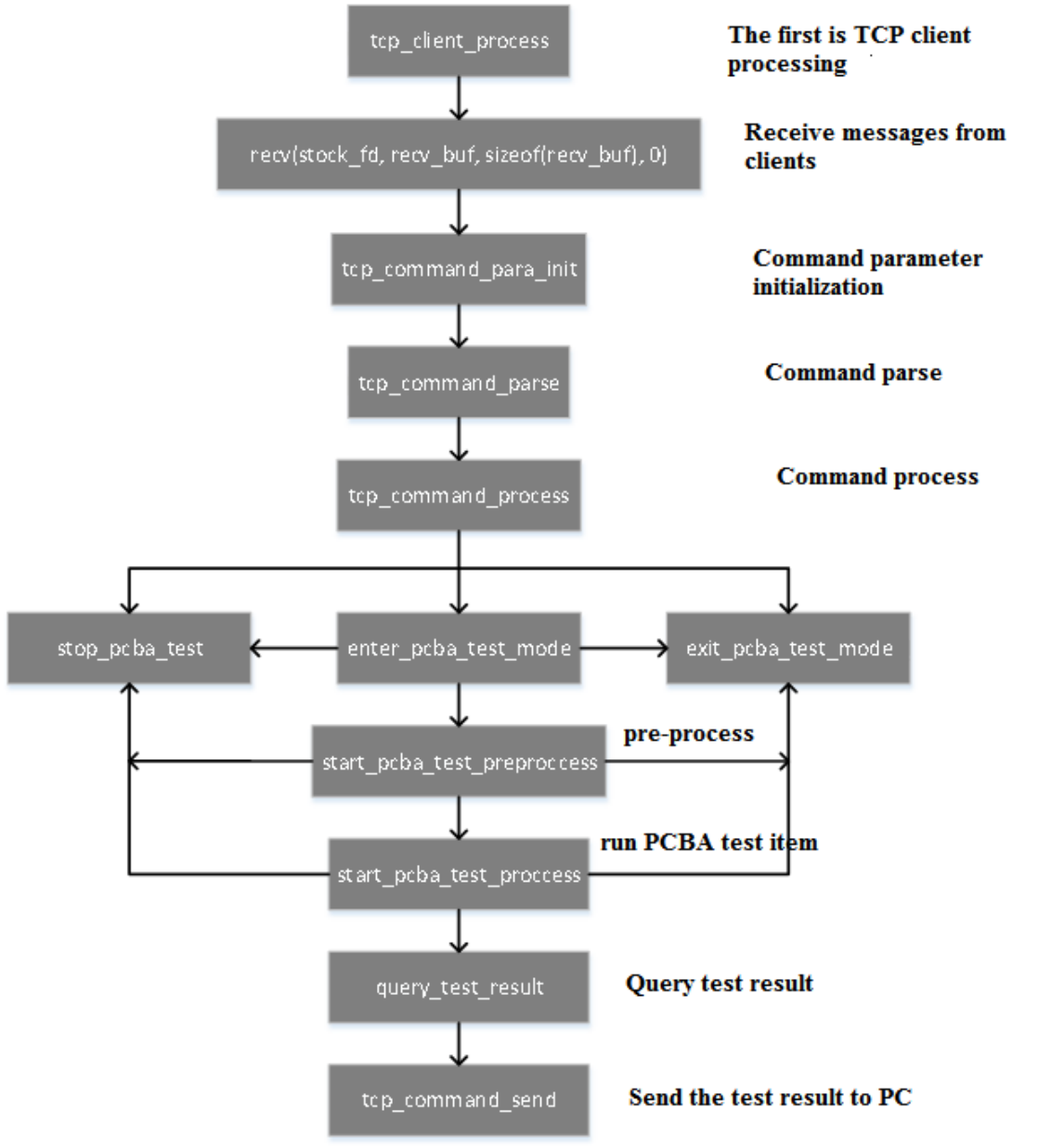
Figure 3-1 Test Code Framework on the PCBA Device Side
3.3 Firmware Generation
At present, the PCBA test program can be compiled in two ways. One is to generate a rootfs firmware separately by PCBA test configuration, and download into the rootfs partition separately. After the system starts, it will directly enter PCBA test environment. At this time, the connection will connect the device to PC, and the PCBA test tool can be used to test. The other way is to integrate the PCBA test program into the recovery mode to test, and write the special PCBA test command in the misc to start the PCBA test program. After the test is finished, the PCBA test command in the misc is cleared, and the system will enter the normal system after rebooting. There are advantages and disadvantages to both ways. When memory is limited, you can choose the first one. The disadvantage is that you need to download the rootfs partition twice, download the firmware of the PCBA test at a time, and then download the normal system firmware after completion. When memory is sufficient, you can choose the second way, and the test is
automatically restarted to enter the normal system after the test is completed and no need to download the firmware again.
3.3.1 Generate rootfs Firmware Separately
- PCBA Configuration File (Buildroot) Within the buildroot/configs/ directory, if the target platform’s corresponding PCBA configuration file rockchip_rkxxxx_pcba.defconfig (where xxxx denotes the specific RK chip platform model) is not found, you may create a new PCBA configuration file using any functional rootfs system defconfig file from the buildroot/configs/ directory as a base template. Integrate all PCBA functional modules and necessary configuration parameters for testing into this new file. Critical Configurations The rockchip_rkxxxx_pcba.defconfig file must include the following core configurations:
#include "base/pcba.config"
Configuration Recommendations: Based on actual testing requirements, add corresponding functional module configurations to defconfig . Taking the RK3328 platform as an example, if support is needed for the following test items: Wi-Fi functionality testing, Bluetooth functionality testing, camera functionality testing, audio playback testing, audio recording testing, USB drive testing then add the following configuration items or configuration files to the configuration file, as shown below:
#include "fs/vfat.config"
#include "multimedia/audio.config"
#include "multimedia/camera.config"
#include "multimedia/gst/audio.config"
#include "multimedia/gst/camera.config"
#include "multimedia/gst/rtsp.config"
#include "multimedia/gst/video.config"
#include "multimedia/mpp.config"
#include "wifibt/bt.config"
#include "wifibt/wireless.config"
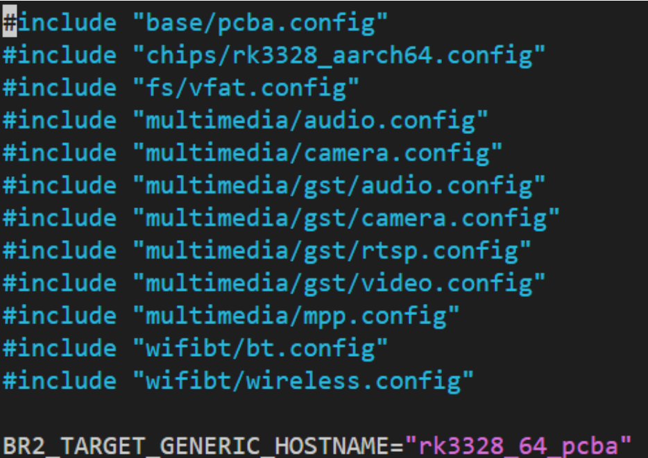
Figure 3-2 Specific Configuration of PCBA in Root File System
-
Verify the buildroot make environment Confirm the existence of the buildroot/package/rockchip/rockchip-pcba/ directory, which must contain the Config.in and rockchip-pcba.mk configuration files to ensure a complete build environment.
-
Compile with buildroot pcba After preparing the configuration files, execute environment initialization in the SDK root directory:
source envsetup.sh
Then select the corresponding PCBA configuration combination number for the chip platform in the automatically generated lunch menu, and execute the compilation command:
make rockchip-pcba
Update Compilation Notes: If you modify the PCBA source code or related configuration items, execute the following command to perform a full rebuild:
make rockchip-pcba-dirclean
make rockchip-pcba-rebuild
- Generate the rootfs.img firmware Add the following configuration to the board-level configuration file rockchip_rkxxxx_evb_defconfig :
RK_BUILDROOT_BASE_CFG="rkxxxx_pcba"
Then execute the compilation command:
./build.sh buildroot
This will generate rootfs.img . Note:
-
You need to modify the buildroot/package/rockchip/partinit/partinit.mk file and delete ln -s userdata data . This soft link will link userdata to the data directory, causing the pcba test program to be overwritten by userdata partition. If you need this soft link, you need to modify the mk file of pcab and install the pcba test program to other directory.
-
If the following error prompt is encountered during compilation:
processing option: pcba
Skipping build_pcba for missing configs:  RK_CFG_PCBA.
It means that the device / rockchip /. Boardconfig.mk board level configuration file needs to be modified at the same time. Add RK_ CFG_ PCBA item to the specific platform configuration, such as rk3308 platform, as follows:
export RK_CFG_PCBA=rockchip_rk3308_pcba
Similar to other platforms, add rockchip_ rkxxxx_ PCBA is enough.
3.3.2 Compile into Recovery
In order to facilitate PCBA test and finish PCBA test by only flashing firmware once and the machine can be reboot to enter the normal system after the test is completed. The PCBA test program can be integrated into the recovery mode for testing. If you need to update the misc partition for the first time (there is a the special command to enter the PCBA test in the misc partition), start the PCBA test, the detailed commands are shown in Figure 3-7, the misc.img content can be modified by UE or other hex editor. The PCBA test program of RK3308 EVB board is compiled as follows: The detailed PCBA configuration file is shown in Figure 3-3 below. The configuration file is located in: /buildroot/configs/rockchip/pcba_test.config root directory.
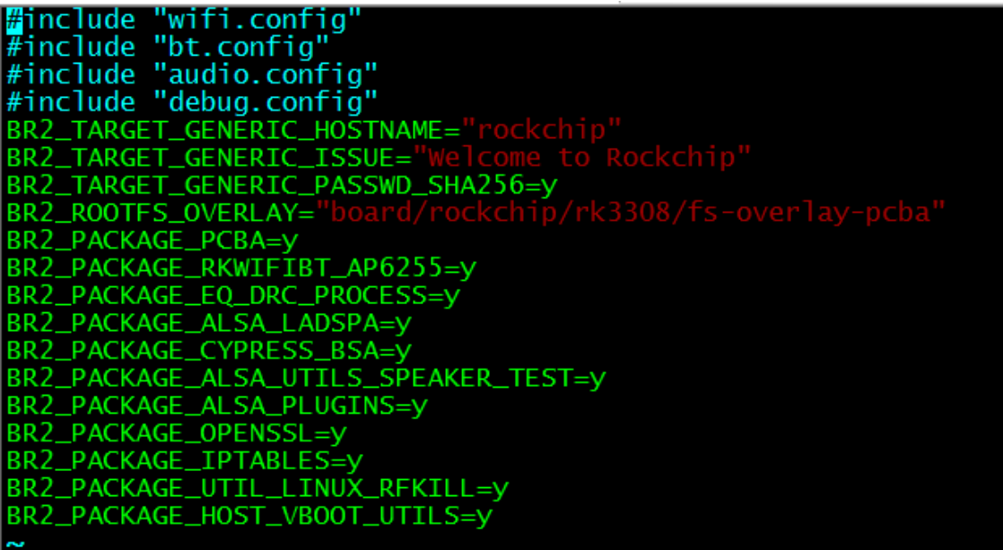
Figure 3-3 Detailed PCBA Configurations in Recovery Note: Items in this configuration may only be suitable for RK3308 platform project, if it is other platform, some of the configurations may be added or deleted according to the needs of the platform, so as to adapt the hardware and software configuration of the platform. Recovery configuration: (recovery configuration directory: buildroot/configs/rockchip_rk3308_recovery_defconfig )
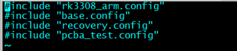
Figure 3-4 Detailed Configuration of Recovery As seen from the above figure, the detailed configuration of PCBA is included in the recovery configuration file. Execute in the project root directory:
./build.sh recovery
The executable file after compiling are shown below:
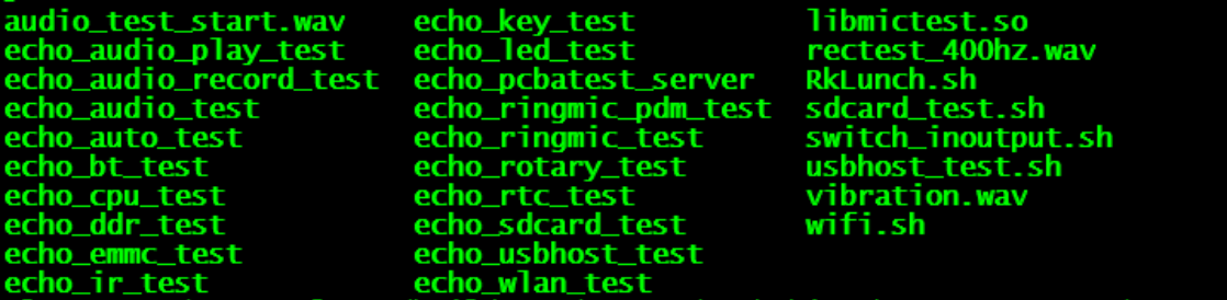
Figure 3-5 Compilation Result of the PCBA Test Item Code
Due to the different hardware design, customers need to modify the test item code in the exteral/rk_pcba_test according to your own board level configuration. The code provided in the SDK is only adapted for RK EVB boards, and some test item codes may not be adapted to customized hardware. If you modify the PCBA test code of device, please execute the following command in the SDK project root directory after modifying the code:
make pcba-rebuild
Then execute ./build.sh recovery , will generate ecovery.img in the ./buildroot/output/rockchip_rk3308_recovery/images/ directory: Execute the following command in the root directory:
./mkfirmware.sh
To generate all partition firmware under the root directory rocketdev/ . Download the firmware recovery.img into the recovery partition. PCBA compilation methods of other platforms refer to the documentations of each platform. Notice:
- The fstab in the root directory /buildroot/board/rockchip/rk3308/fs-overlay-pcba/etc is not needed, for which will overwrite the fstab generated by partinit, causing the recovery mode to be abnormal.
~/3308/buildroot/board/rockchip/rk3308/fs-overlay-pcba/etc $ ls
asound.conf  init.d  inittab  profile.d
-
The buildroot/package/rockchip/partinit/partinit.mk file should be modified and ln -s userdata data should be deleted, this soft link will link userdata to the data directory, causing the pcba test program to be overwritten by the userdata partition. If you need this soft link, you need to modify the pck mk file and install the pcba test program to other directories.
-
You need to modify buildroot/package/rockchip/pcba/Config.in and pcba.mk as follows:
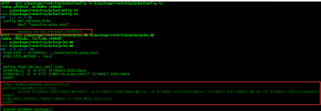
Figure 3-6 Modification in pcba config and Makefile
The modification removes the soft link of data directory to userdata in the recovery mode, otherwise it will affect audio playback function during booting of the normal system. Re-create the data directory and copy the binary program generated in the userdata directory to the data directory.
-
PCBA is tested in recovery. The misc partition needs to be downloaded with misc.img og pcba test command.
-
As shown in Figure 3-7, the command format of pcba in the misc:
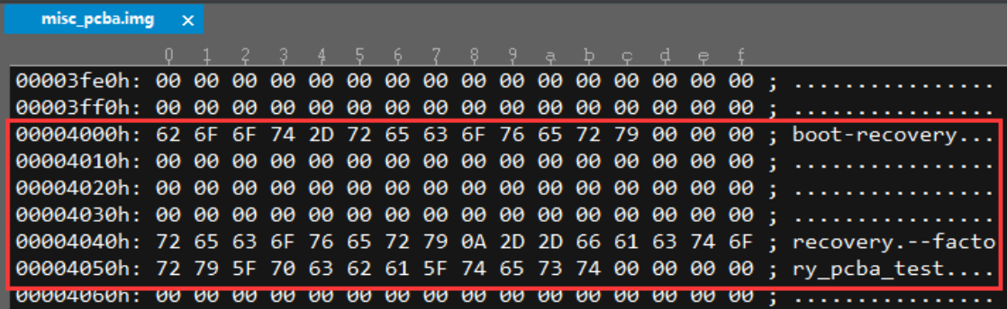
Figure 3-7 Command Format for PCBA Test in misc.img
- The PCBA test tool end must configure “needreboot”: true in the JSON file. It will sent reboot information to the device after the test is completed and successful. After receiving the message, the device will clear the factory_pcba_test command in the misc partition and reset it to the wipe_all command which is used to format the user partition (userdata partition) in the next recovery mode and enter the normal system.Below is the “meta” configuration containing “needreboot” .
"meta": {
    "version": "1.0",
    "author": "rockchip_dep3",
    "description": "PCBA Motherboard Functional Testing Configuration",
    "needreboot": true
},
- Modify echo_pcbatest_server.c. When test pass, prepare to reboot the device. The exit_pcba_test_mode interface as shown below, add recovery mode judgment and reset the factory command (write wipe_all command in misc), ready to reboot and then enter the recovery mode to format user partition and enter the normal system.
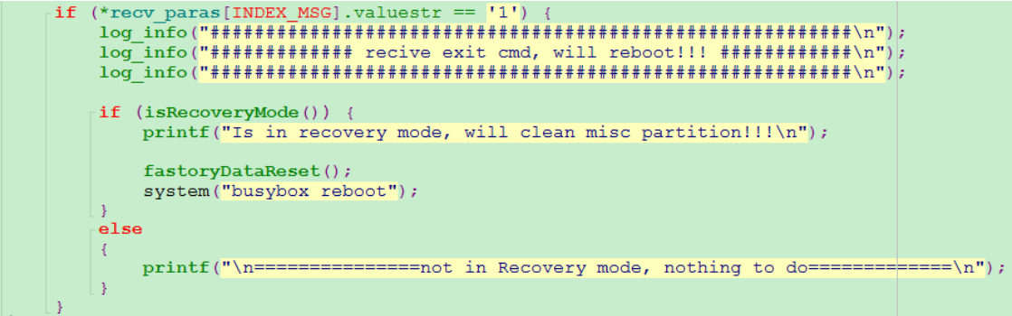
Figure 3-9 Modification in the echo_pcbatest_server.c
- Problems that may be encountered in the recording test
If there are more than 2 channels in the PCBA recording test, for example, use the following command to record:
arecord -Dhw:0,0 -f S16_LE -r 48000 -c 4 /tmp/record.wav
4-channel recording was used here, but the result may be only 2 channels data. When this case happens, check the configuration in Buildroot/configs/rockchip/audio.config . BR2_PACKAGE_PULSEAUDIO=y and BR2_PACKAGE_PULSEAUDIO_DAEMON=y should be turned off.
buildroot/configs$ git diff rockchip
diff --git a/configs/rockchip/audio.config b/configs/rockchip/audio.config
index 8cf1207..f23cb5a 100644
--- a/configs/rockchip/audio.config
+++ b/configs/rockchip/audio.config
@@ -8,8 +8,8 @@ BR2_PACKAGE_ALSA_UTILS_ALSACONF=y
 BR2_PACKAGE_ALSA_UTILS_AMIXER=y
 BR2_PACKAGE_ALSA_UTILS_APLAY=y
 BR2_PACKAGE_LIBMAD=y
-BR2_PACKAGE_PULSEAUDIO=y
-BR2_PACKAGE_PULSEAUDIO_DAEMON=y
+#BR2_PACKAGE_PULSEAUDIO=y
+#BR2_PACKAGE_PULSEAUDIO_DAEMON=y

 # Copy alas configs
 BR2_PACKAGE_ALSA_CONFIG=y
4. PCBA Test with Screen
Some RK platforms support displaying with a screen. Therefore, for PCBA testing without computers, you can directly display PCBA test items and test results on the screen just like Android PCBA test running on other platforms of RK. This section will introduce the PCBA test in this case. It will take PX3-SE platform as an example to describe the PCBA test under Linux system with screen in details. Due to platform differences, users should adjust the corresponding configurations according to their own platforms.
4.1 Test Code
All PCBA test code and on-screen display code are located in the external/rk_pcba_test directory. The PCBA test code for the Linux platform inherits the testing approach from the Android platform, utilizing the configuration file rk_pcba_test/test_config.cfg to specify which test items should be executed and displayed. For details on a specific test item, refer to the test module configuration examples within test_config.cfg . Users wishing to add custom test items may also use a test case from the rk_pcba_test/pcba_minui directory as a template to
extend and write their own test item code. After completion, remember to add it to cMakeList.txt to include it in the build.
4.2 Compilation and Configuration Introduction
Configuration files of PCBA package under Buildroot: buildroot/package/rockchip/rockchip-pcba/Config.in file:
config BR2_PACKAGE_PCBA
    bool "Rockchip pcba test"
    help
      Rockchip pcba test.

if BR2_PACKAGE_PCBA

config BR2_PACKAGE_PCBA_SCREEN
    bool "pcba with screen"
    select BR2_PACKAGE_LIBDRM
    select BR2_PACKAGE_LIBPNG
    select BR2_PACKAGE_LIBPTHREAD_STUBS
    select BR2_PACKAGE_LIBZIP
    help
      Enable screen support for PCBA testing.
      Note: This will automatically enable the required graphics
      libraries (libdrm, libpng, libzip) and threading support.

endif
Function Description: Rockchip PCBA Test Program Integration Conditional Dependencies: When BR2_PACKAGE_PCBA_SCREEN is enabled, the following dependency packages are automatically selected: - BR2_PACKAGE_LIBDRM : Direct Rendering Manager graphics library - BR2_PACKAGE_LIBPNG : PNG image processing library - BR2_PACKAGE_LIBPTHREAD_STUBS : POSIX thread compatibility library - BR2_PACKAGE_LIBZIP : ZIP compressed file processing library Explanation for buildroot/package/rockchip/rockchip-pcba/rockchip-pcba.mk :
################################################################################
#
# rockchip-pcba project
#
################################################################################

ROCKCHIP_PCBA_SITE = $(TOPDIR)/../external/rk_pcba_test
ROCKCHIP_PCBA_SITE_METHOD = local

ifeq ($(BR2_PACKAGE_PCBA_SCREEN),y)
ROCKCHIP_PCBA_CONF_OPTS = -DROCKCHIP_PCBA_WITH_UI=ON
ROCKCHIP_PCBA_DEPENDENCIES = zlib libpthread-stubs libpng libdrm
endif

define ROCKCHIP_PCBA_INSTALL_TARGET_CMDS
    $(INSTALL) -d -m 0755 $(TARGET_DIR)/data
    $(INSTALL) -D -m 0755 $(@D)/rk_pcba_test/* $(TARGET_DIR)/data
endef

$(eval $(cmake-package))
This .mk file defines corresponding PCBA configuration macros based on platform configurations specified in the configs directory. Explanation: If a screen-equipped PCBA test is configured (i.e., BR2_PACKAGE_PCBA_SCREEN=y ), the PCBA configuration defines PCBA_WITH_UI . It also defines dependencies on related libraries: zlib, libpthread-stubs, libpng, and libdrm. Note: PCBA_CONF_OPTS and PCBA_DEPENDENCIES represent syntax specific to mk files. If your current platform requires support for screen-equipped PCBA testing, add your platform’s definitions by following the approach used for other platforms in this rockchip-pcba.mk file. The .mk file defines the corresponding PCBA configuration macro based on the definition of the platform configuration in the configuration file in configs.
ifeq ($(BR2_PACKAGE_PX3SE),y)
ifeq ($(BR2_PACKAGE_PCBA_SCREEN),y)
PCBA_CONF_OPTS = -DPCBA_WITH_UI=ON
PCBA_DEPENDENCIES = zlib libpthread-stubs libpng libdrm
endif
PCBA_CONF_OPTS += -DPCBA_PX3SE=ON
endif
Note: if PX3-SE platform is defined, that is, BR2_PACKAGE_PX3SE=y , and the PCBA test with screen display is configured, that is, BR2_PACKAGE_PCBA_SCREEN=y , the configuration item of PCBA defines PCBA_WITH_UI , and define the dependent libraries zlib libpthread-stubs libpng libdrm at the same time. As long as PX3-SE platform is defined, the configuration items will define the PCBA_PX3SE macro. Note: PCBA_CONF_OPTS and PCBA_DEPENDENCIES here are a unique syntax in the mk file. If your platform needs to support PCBA test with screen, follow the definition of other platforms in the pcba.mk file, and add the definition of your platform. Key configurations of configs/rockchip_px3se_pcba_defconfig are as follows:
#include "base/pcba.config"
......
BR2_PACKAGE_PX3SE=y
BR2_PACKAGE_PCBA_SCREEN=y
......
4.3 Execution
Please refer to board/rockchip/px3se/fs-overlay-pcba/data/RkLunch.sh
#! /bin/sh
if [ -f "pcba-core" ]; then
pcba-core &
fi

echo_pcbatest_server &
echo_auto_test echo_wlan_test &
echo_auto_test echo_bt_test &
echo_auto_test echo_ddr_test &
echo_auto_test echo_emmc_test &
echo_auto_test echo_rtc_test &

board/rockchip/px3se/fs-overlay-pcba/etc/init.d/S98_lunch_init
source /etc/profile.d/RkEnv.sh

case "$1" in
  start)
        source /data/RkLunch.sh
        printf "insmod vcodec service...\n"
        insmod /system/etc/firmware/vcodec_service.ko
        ;;
  stop)
        printf "stop finished\n"
        ;;
  *)
        echo "Usage: $0 {start|stop}"
        exit 1
        ;;
esac
exit 0
Put RkLunch.sh in the boot initialization script to execute pcba-core and other boot test items in the background after booting.
5. Appendix
5.1 Summary of Common Errors
5.1.1 Opening PCBA Tool Error
As shown in Figure 5-1, the following error “Initialize RKupdate dll failed” is prompted when the tool is opened.
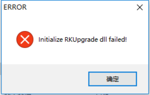
Figure 5-1 Opening PCBA Tool Error Analysis: This error is caused by a wrong file path configuration when installing the tool. Solution: As shown in the figure below, in the tool installation directory, open config.ini and modify the path LogPath and TestPath as the current tool installation directory. For example, the tool installation path here is in the D:\ROCKCHIP\PCBATool directory. Set LogPath= D:\ROCKCHIP\PCBAToo\Log\ Set TestPath=D:\ROCKCHIP\PCBAToo\test\
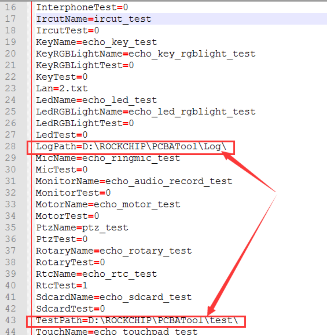
Figure 5-2 pcba config.ini Configuration File
5.1.2 Adb Forward Fail
As shown in Figure 5-3, the tool prompts “adb forward fail” after opening the tool:
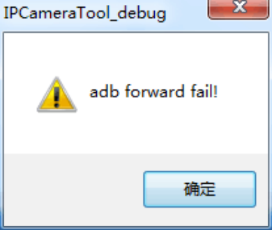
Figure 5-3 adb Forward Fail Analysis: The reason for this problem may be that ADB recognizes multiple devices, causing the tool to fail to properly start the ADB program to start the service. Solution: Open a command window on PC, and cd to the adb tool installation path on the CMD window. Execute “adb devices” command to check whether there are multiple devices connected. If there are multiple devices connected to the PC, unplug other devices to solve this problems. Or kill the adb service and re-open it. Execute the following command in CMD command line:
adb kill-server
adb start-server
Try again later.
5.1.3 Unable to Connect Device under Window 10
If you run the PCBA test tool under Window 10, you may encounter an ADB device that is not properly connected to device. The reason for this problem is program is incompatibility with the system. The solution is that try to open the test program using win7 compatibility mode. Right-click on the tool icon –> Properties –> Compatibility Tab –> “Run this program in compatibility mode”.
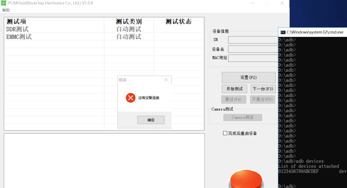
Figure 5-4 Device Cannot Be Connected Properly under Win 10 System
5.1.4 Upload File Fail
If “upload file fail” dialog appears, it is because the test service program echo_pcbatest_server of the PCBA is not successfully running on the current system, causing the tool to try to push a binary from local ADB to device, but there is no this file in the “test” directory of local tool installation directory, so this error dialog will be reported. Solution: please check the device configuration to ensure that:
-
There are “echo_pcbatest_server” and other test item bin programs are all in the /data directory of the device;
-
The PCBA test related service program and automatic test items are successfully started with the system.
Chinese baseline, English and older-source reconciliation
- Both main sources are V1.2.0, tool V1.7. ApplicationNote is V1.1.2, tool V1.6. The newer source adds EMMC, RTC and automatic CAMERA descriptions, JSON meta/test_group/mes_config and VS2022 with v143 MFC. The old workflow uses VS2008 SP1 and checkbox selection saved in config.ini for automatic loading next launch. These are separate generations.
- English retains the old camera-button section 1.4.3, deleted in Chinese; Chinese reboot is 1.4.3. It is retained here as historical English material. Dev_Plateform, V4l2_test and nv12_to_bmp_main concern that old button. The new automatic camera test uses v4l2_capture.sh and photo_check.sh. CamData is retained but unused.
- The old reboot checkbox was disabled by default and protected by a fixed password obtainable from FAE; the newer setting is JSON needreboot. The system_a/system_b A/B example is a source layout, not a universal ArmSoM layout.
- New standalone builds use make rockchip-pcba, rockchip-pcba-dirclean, rockchip-pcba-rebuild and ./build.sh buildroot. Old commands were make pcba, make pcba-dirclean, make pcba-rebuild and ./build.sh pcba. Old RK3308 outputs under buildroot/output/rockchip_rk3308_pcba/images/ include rootfs.cpio, rootfs.cpio.gz, rootfs.ext2 and rootfs.squashfs; select the appropriate full rootfs image for the filesystem, not simply pcba.img.
- The old overlay workflow requires BR2_ROOTFS_OVERLAY and BR2_PACKAGE_PCBA. If board/rockchip/rkxxxx/fs-overlay-pcba is absent, adapt an RK3308 copy. data/RkLunch.sh is included through etc/init.d/S98_lunch_init to start the test service at boot. Do not assume those old paths fit the current SDK.
- Chinese recovery changes target buildroot/package/rockchip/rockchip-pcba/{Config.in,rockchip-pcba.mk}; English retains pcba/{Config.in,pcba.mk}. Chinese correctly names recovery.img and rockdev/; English prints ecovery.img and rocketdev/. Chinese is the reference for these differences.
- English chapter 4 retains old PX3-SE macros alongside the updated generic configuration. Historical conditional macros include PCBA_PX3SE, PCBA_3308 and PCBA_3229GVA. The old PX3-SE ring-microphone example builds echo_ringmic_test.c and links rk_pcba_test/libmictest.so. This does not establish support for arbitrary boards.
- Protocol headers spell TPYE whereas JSON uses TYPE. The successful EXIT response uses CMD instead of RES in the source. KEY_test, KEY-TEST and key_test differ; verify the implementation. VERIFY is described as test completion in the table and result confirmation in the example. Nine protocol tables were reconstructed without the PDF extractor’s clipped columns.
- The loading text calls the test list part 3, while the interface overview calls it part 2. Private network addresses, MES server and account fields are source examples only and were not accessed. The Chinese product table spells RK3358; this is retained rather than silently changed to RK3588. Check identifiers and platform support against the SDK.
Chinese Bluetooth examples identify RK3229GVA, PX3-SE and RK3308 as older platforms that cycle Bluetooth power; RK3328, RK3326, RK3358 and PX30 are newer examples that load firmware at boot without that cycle. These are source-specific examples.