
This article preserves the complete technical body (PDF pp.9–84) of the 84-page English V3.0.2 source. No Chinese source was supplied. Chinese and Russian are complete translations of that body; all languages use the same independent original figures from the English PDF, including Chinese UI labels already present. The omitted vector equations on p.64 are also restored; equations, tables and code are editable. Log prefixes/end lines already cropped in the source and unrendered source image references are not invented.
This is an ArmSoM platform reference without hardware validation. Verify the actual board, SoC, ISP, Sensor, SDK/BSP, AIQ, IQ Tool and kernel. The p.2 product table lists RK3566/RK3568 with a blank kernel field; p.9 identifies ISP30/RK3588, while p.77 mentions RK1109. These conflicting scopes are recorded rather than generalized to all ArmSoM boards. Source example results are not ArmSoM measurements. No code, camera configuration or IQ update was executed.
Retained technical version information: V2.0.0 changes IQ XML to JSON and supports AIQ V2.0x60.0/IQ Tool V2.0.2; V2.0.1 adapts ISP21/RK356X; V3.0.0 adapts ISP30/RK3588; V3.0.1 removes manual CCM/3DLUT JSON configuration, with online automatic mode only; V3.0.2 AWB simulation targets IQ Tool V2.1.0. XML examples, not-yet-supported statements and different ISP references in the body remain traceable to the source.
| SoC | Kernel (source p.2) |
|---|---|
| RK3566 / RK3568 | Blank in source; unspecified |
EDITORIAL-NOTES. ArmSoM · Rockchip Linux
1 Overview
ISP30 related color adjustment modules include auto white balance (AWB), color correction (CC), and three dimension look up table (3dlut)
ISP21 (RK3566/RK3568) and ISP20 (RV1126/RV1109) CCM and 3DLUT modules are not different, and the differences to be aware of for AWB debugging are as follows
(1) Multiwindow multiple child window configurations are not supported on ISP21
(2) 3dyuv algorithm upgrade
(3) The additional box only supports deducting white points, and does not support use as an additional point light source
(4) Added the function of different brightness and different weight of white point
(5) Added block weight function
(6) The xy domain is configured with two sizes of boxes per light source, one less than ISP20
ISP30 (RK3588) and ISP21 (RK3566/RK3568) CCM and 3DLUT modules are no different, but 3DLUT modules add tools (see 3DLUT module description), AWB debugging needs to pay attention to the differences are as follows:
(1) The additional box supports deducting white points and can also be used as an additional point light source
(2) The tool has upgraded the YUV threshold debugging (see Example 2)
2 AWB
2.1 Feature description
The automatic white balance algorithm can automatically calculate WB gain (the white balance gain of the R G B channel) and multiply it with the RGB channel to restore the white affected by ambient light to pure white, ensuring that the camera imaging color is consistent with the real color of the object under various light conditions. When there is a white point in the scene, WB gain is calculated based on the automatically detected white point, and when there is no white point in the scene, WB gain is obtained by the simple color method. The color adaptation module adjusts the target of white balance correction so that the image after white balance correction is as consistent as possible with the appearance perceived by the human eye. Tone adjustment module, adjust the overall tone according to your preference. Automatic white balance consists of hardware statistics and software policies, as shown in the AWB flowchart
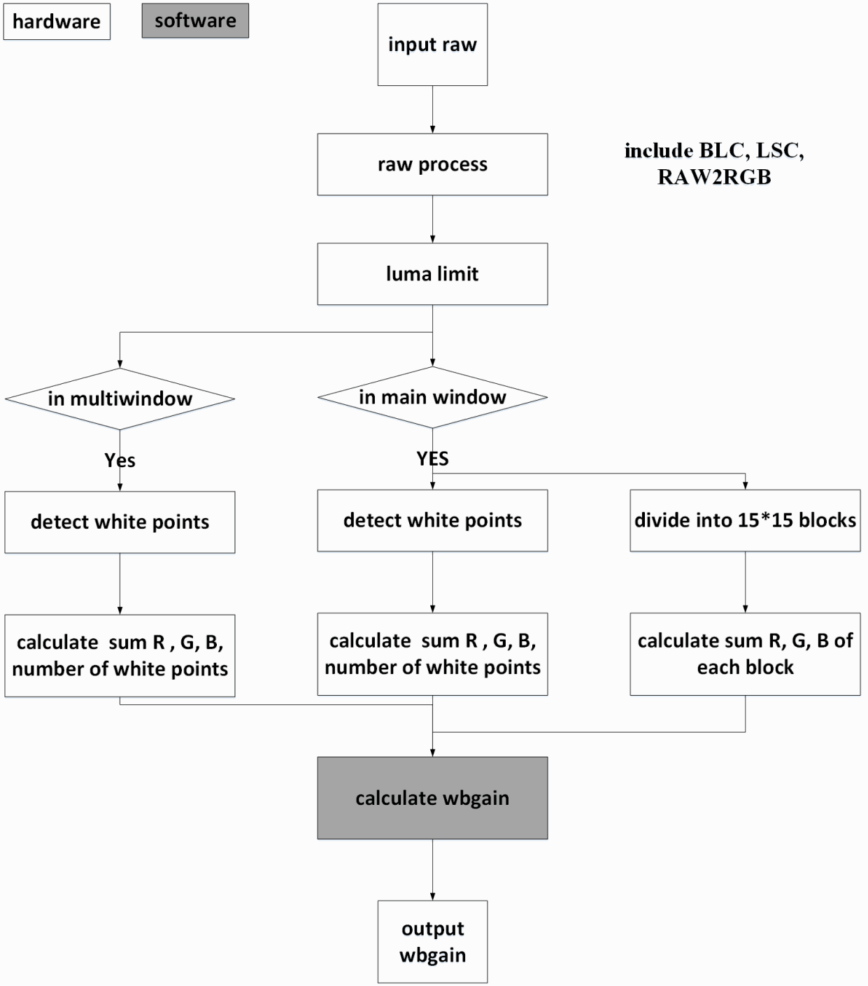
English source figure, PDF p.10, #15.
Figure AWB flow
2.2 Key parameters
ISP21 parameters are shown in the wb_v21 node of the IQ json file;
2.2.1 White balance correction enabled and white balance mode selection
Under the control node
| Name | Description |
|---|---|
| bypass | The value is 0 or 1 0 means to do white balance correction, and the white balance gain used is controlled by mode 1 means no white balance correction is performed |
| mode | The value CALIB_WB_MODE_AUTO or CALIB_WB_MODE_MANUAL CALIB_WB_MODE_MANUAL indicates that the manual white balance gain is used CALIB_WB_MODE_AUTO which means that the white level gain is calculated using the automatic white balance algorithm |
2.2.2 Manual white balance parameters
Under the manualPara node
| name | description |
|---|---|
| mode | The value CALIB_MWB_MODE_CCT or CALIB_MWB_MODE_WBGAIN or CALIB_MWB_MODE_SCENE |
| cfg.wbgain | When the value range [0.5-3.9] mode == CALIB_MWB_MODE_WBGAIN, this parameter is applied to manual white balance |
| cfg.scene | The value is CALIB_WB_SCENE_INCANDESCENT (indicating a light source) or CALIB_WB_SCENE_FLUORESCENT (for CWF light source) or CALIB_WB_SCENE_WARM_FLUORESCENT (for U30 light source) or CALIB_WB_SCENE_DAYLIGHT (for D65 light source) or CALIB_WB_SCENE_CLOUDY_DAYLIGHT (for D50 light source) or CALIB_WB_SCENE_TWILIGHT (indicating HZ light source) or CALIB_WB_SCENE_SHADE (for D75 light source) Mode == When CALIB_MWB_MODE_SCENE, this parameter is applied to manual white balance |
| cfg.cct | The value of CCT is [0-10000] The CCRI value is [-2,2], and the CCRI value is 0, which is approximately the light source on the Planck locus in the chromaticity diagram Mode == When CALIB_MWB_MODE_CCT, this parameter is applied to manual white balance |
Several configurations are:
Auto White Balance + White Balance Correction Enabled (recommended)
control.bypass = 0;
control.mode = CALIB_WB_MODE_AUTO;
White balance correction is not enabled
control.wbBypass = 1;
Manual white balance + white balance correction enabled
control.wbBypass = 0;
control.mode = CALIB_WB_MODE_MANUAL;
manualPara.mode = CALIB_MWB_MODE_WBGAIN;
manualPara.cfg.wbgain = [1,1,1,1];
2.2.3 Auto white balance parameters
The following parameters are all in auto white balance mode. In the autoPara (ISP20 and ISP21 members are different) and autoExtPara (ISP20 and ISP21 members are the same) nodes. Subsequent parameters are members of both structs.
2.2.4 hdrPara
Corresponding to the autoPara.hdrPara struct, for the hdr sensor, you can specify one of the long, medium, and short frames to perform white balance related statistics, and it is recommended to use the automatic mode.
| Name | description |
|---|---|
| frameChooseMode | Values CALIB_AWB_INPUT_RAW_FIXED, CALIB_AWB_INPUT_RAW_AUTO, CALIB_AWB_INPUT_BAYERNR, and CALIB_AWB_INPUT_DRC. CALIB_AWB_INPUT_RAW_FIXED Fixed selection of long or short frame raw, specified by frameChoose; CALIB_AWB_INPUT_RAW_AUTO automatically select long or short frames of RAW for white balance statistics; CALIB_AWB_INPUT_BAYERNR Select the output of the bayer2dnr module; CALIB_AWB_INPUT_DRC Select the output of the DRC module; |
| frameChoose | hdr mode and frameChooseMode is CALIB_AWB_INPUT_RAW_FIXED valid; Under two frames HDR: the value is 0 or 1; 0 Select short frames (raw_in_short) for white balance statistics; 1 Select long frames (raw_in_long-) for white balance statistics; |
2.2.5 limitRange
(1)Corresponding to the autoPara.limitRange structure in JSON, the pixel range of white point statistics is entered, and points beyond the range are not counted. Want to increase the number of white points to increase the value range; To improve the accuracy of the white point, adjust the range so that the points participating in the count are not too dark or too bright. Different ranges of ambient brightness configurations are supported, and the actual range is obtained by linear interpolation of these configurations.
| Name | Description |
|---|---|
| lumaValue | The ambient brightness range is 0-255000 |
| maxR | The right boundary of the R-channel value range, the recommended value is 255-black level- 3, and the maximum value is 255 |
| minR | The left boundary of the R-channel value range, the recommended value is 3, and the minimum value is 0 |
| maxG | The right boundary of the G-channel value range, the recommended value is 255-black level- 3, and the maximum value is 255 |
| minG | The left boundary of the G-channel value range, the recommended value is 3, and the minimum value is 0 |
| maxB | The right boundary of the B channel value range, the recommended value is 255 - black level -3, and the maximum value is 255 |
| minB | The left boundary of the B channel value range, the recommended value is 3, and the minimum value is 0 |
| maxY | The right boundary of the Y-channel value range, the recommended value is 255-black level- 3, and the maximum value is 255 |
| minY | The left boundary of the Y-channel value range, the recommended value is 3, and the minimum value is 0 |
2.2.6 mainWindow
The awb statistics main window configuration corresponds to the autoPara.mainWindow structure in JSON. Auto- configuration mode is recommended; For special applications, such as when the colors hading around the wide- angle lens is heavy, the main window size can be customized to reduce the impact on AWB statistics
| Name | Description |
|---|---|
| mode | Set the value CALIB_AWB_WINDOW_CFG_FIXED or CALIB_AWB_WINDOW_CFG_AUTO CALIB_AWB_WINDOW_CFG_AUTO to automatically configure the main statistics window to RAW size, the recommended value is CALIB_AWB_WINDOW_CFG_FIXED Custom Statistics Window Size |
| window | When mode is 1, enable window=[h_offset,v_offset,h_size,v_size], h represents the horizontal direction, v represents the vertical direction of h_offset, v_offset, h_size, v_size value is 0-1 The value is [0, 0, 1, 1] indicates the use of full window, that is, the size of RAW |
2.2.7 downScaleMode
Corresponds to the autoPara.downScaleMode member in JSON
| Name | Description |
|---|---|
| downScaleMode | The value CALIB_AWB_DS_4X4 or CALIB_AWB_DS_8X8 CALIB_AWB_DS_4X4 indicates that raw 4x4 downsampling is used as the input of the AWB statistics module, and the downsampling multiples of the horizontal and vertical directions are ds_w, and the ds_h are 4 CALIB_AWB_DS_8X8 indicates that the raw 8x8 downsampling is used as the input of the AWB statistics module, and the downsampling multiples in the horizontal and vertical directions ds_ w, ds_h are all 8, default |
2.2.8 lscBypassEnable
Corresponds to the autoPara.lscBypassEnable member in JSON
| Name | Description |
|---|---|
| lscBypassEnable | The value is 0 or 1; 0 Lens shading correction (LSC) of the white balance statistical pathway is not enabled; 1 LSC enable for the white balance statistical pathway; LSC module that does not affect the main ISP path |
2.2.9 blkStatisticsEnable
Corresponds to the autoPara.blkStatisticsEnable member in JSON
| Name | Description |
|---|---|
| blkStatisticsEnable | The value is 0 or 1; 0 White balance statistics 15x15 block statistics function is not enabled; 1 White balance statistics 15x15 block statistics function enabled; |
2.2.10 blkMeasureMode
Corresponds to the autoPara.blkMeasureMode member in JSON
| Name | Description |
|---|---|
| blkMeasureMode | Value CALIB_AWB_BLK_STAT_MODE_ALL_V201 or CALIB_AWB_BLK_STAT_MODE_REALWP_V201; CALIB_AWB_BLK_STAT_MODE_ALL_V201 refers to the cumulative value of all points in the 15x15 block statistics block, the default value; CALIB_AWB_BLK_STAT_MODE_REALWP_V201 refers to the cumulative value of the white point in the 15x15 block statistics block; |
2.2.11 The white point detection process for hardware
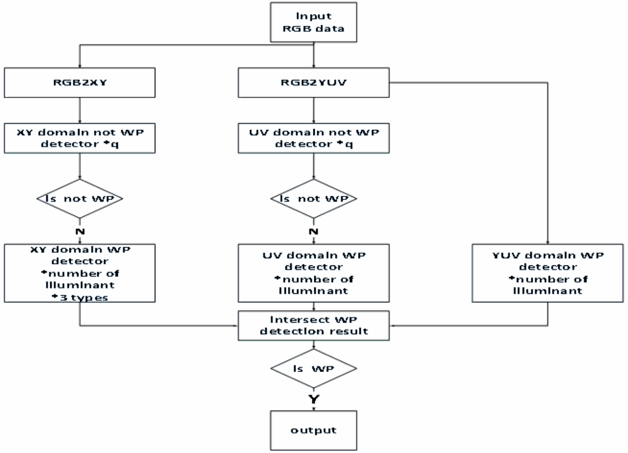
English source figure, PDF p.15, #51.
Figure AWB white point detection process
As shown in the white point flow detection program diagram, determine whether it is a white point from the three domains
| Name | Description |
|---|---|
| uvDetectionEnable | The value is 0 or 1; 0 UV domain non-white point filtering is not enabled; 1 UV domain non-white point filtering is enabled, select the UV domain white point according to the white point condition; |
| xyDetectionEnable | The value is 0 or 1; 0 XY domain non-white point filtering is not enabled; 1 XY domain non-white point filtering is enabled, select the XY domain white point according to the white point condition; |
| yuvDetectionEnable | The value is 0 or 1; 0 YUV domain non-white point filtering is not enabled; 1 YUV domain non-white point filtering is enabled, select the YUV domain white point according to the white point condition; |
The above three parameters are members of the autoPara junction, when these three parameters are configured to 0, they fall in the statistics window, and the points with the required brightness will be treated as white dots. This can be used when you have no time to calibrate and want to take a cursory look at the effect after auto white balance.
2.2.11.1 RGB2XY
The RGB domain to XY domain transformation parameters are automatically generated by the calibration tool and correspond to the autoPara.rgb2TcsPara structure in JSON
| Name | Description |
|---|---|
| pseudoLumWeight | Make the white point of different light sources as much as possible on a straight line, the parameters are generated by the calibration tool, the value range is 0~1, it is not recommended to adjust |
| rotationMat | Rotate the matrix to make the x-axis characterize the change of the color temperature of the blackbody radiation, and the y-axis to represent the light source with the same temperature variegation, the parameters are generated by the calibration tool, the value range is [-3.99, 3.99], it is not recommended to adjust |
2.2.11.2 XY domain white points detector
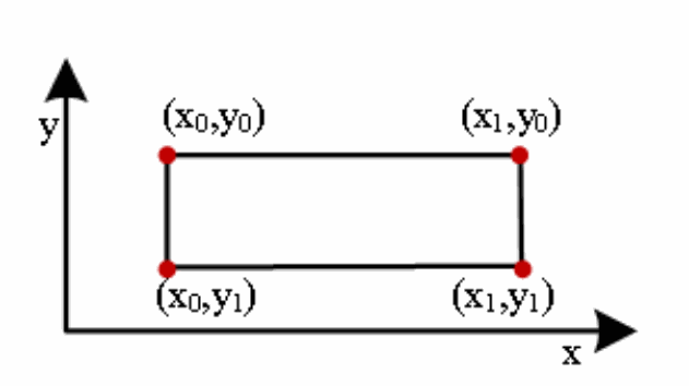
English source figure, PDF p.16, #60.
Figure XY domain white point interval
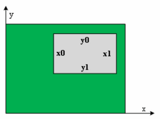
The XY field white point interval is shown above, and the white point inside the rectangular box is the white point. There are two sizes of white point intervals, and the white point interval is shown in the figure [x0,x1,y0,y1]. Manually adjust the white point interval generation on the calibration tool, corresponding to the autoPara.lightSources.xyRegion structure of SON
| Name | Description |
|---|---|
| normal | The white dot interval in the middle box, the value range is [-8,7.99] |
| big | Large box white dot interval, value range [-8,7.99] |
2.2.11.3 UV domain white points detector
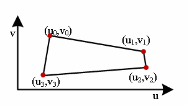
English source figure, PDF p.17, #66.
Figure UV domain white point interval
The UV domain white point interval is shown above, and the white point in the quad box corresponds to the autoPara.lightSources.uvRegion structure of JSON
| Name | Description |
|---|---|
| u | The U coordinate of the UV domain white point condition constitutes a closed loop, such as [u0,u1 u2,u3,u0], the value range [0,255], and the decimal place value can only be 0 or 0.5 Manually adjust the white point interval generation |
| v | The V coordinate of the UV domain white point condition constitutes a closed loop, such as [v0, v1 v2, v3, v0], the value range [0,255], the decimal place value can only be 0 or 0.5 Manually adjusted on the calibration tool to generate |
2.2.11.4 RGB2RYUV
The change parameter of RGB to rotation YUV space corresponds to JSON’s autoPara.rgb2RotationYuvMat matrix
rgb2RotationYuvMat=[u0,u1,u2,uoffset
v0,v1,v2,voffset
y0,y1,y2,yoffset]
| Name | Description |
|---|---|
| u0,u1,u2,v0,v1,v2,y0,y1,y2 | The value range [-1,1) automatically generates an accuracy of 1/2^9 on the calibration tool |
| uoffset,voffset,yoffset | The value range [-255,254] automatically generates an accuracy of 1/2^4 on the calibration tool |
2.2.11.5 RYUV domain white points detector
Determine whether it is a white point by calculating the brightness difference between the point (y0,u0,v0) and the theoretical white point (y’,u0,v0) diff = |y0-y’|in the scene. If diff <th, the point is considered a white point, otherwise it is not a white point. Different white point thresholds th can be set for different positions (distinguished by the u component), as shown by the segmented line dis-th
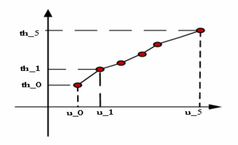
English source figure, PDF p.18, #78.
On the calibration tool, refer to the diff and u of the points (y0, u0, v0) in the scene to adjust the u-th segmented straight line of the corresponding light source to achieve the purpose of correct estimation of white points and non-white point exclusion (this function has not been realized at present), the light source is obtained by the previous XY and UV domain methods, the solid YUV method can not be enabled separately, and it is necessary to use it in conjunction with the XY or UV domain white point detection method.
Corresponds to the structure of autoPara.lightSources.rtYuvRegion in JSON
| Name | Description |
|---|---|
| lineVector | The theoretical white point (y’,u0,v0) is obtained from (y0,u0,v0) to calculate the value range of each component of the required parameter [0,255], and the accuracy is 1/(2^4) It is not recommended to adjust by the calibration tool |
| disP1P2 | The theoretical white point (y’,u0,v0) is obtained from (y0,u0,v0) and the value range of each component of the required parameter is calculated [0,5] obtained by the calibration tool and is not recommended to adjust |
| thcurve_u | The value range of each component of the u-th of the piecewise line u-th is [0,255], integer Note: The difference between two adjacent u components is to the power of 2 |
| thcure_th | The value range of each component of the piecewise line u-th is [0,255] with an accuracy of 1/(2^4) Note: The segmented line u-th must be monotonically increasing |
2.2.11.6 Increases the interval of non-white dots
Generally, the point that falls in the white point interval of XY, UV, and YUV at the same time will be a white point, and some non-white points may also meet this situation, and are located in the center of the range, which is difficult to exclude. In this case, you can add a non-white point interval to the UV or XY space, and any point that falls into this interval will be treated as a non-white point.
The maximum number of non-white dots is 7.
Corresponds to the autoPara.extraWpRange parameter in JSON,
English source figure, PDF p.19, #87.
| Name | Description |
|---|---|
| domain | The value CALIB_AWB_EXTRA_RANGE_DOMAIN_UV or CALIB_AWB_EXTRA_RANGE_DOMAIN_XY CALIB_AWB_EXTRA_RANGE_DOMAIN_UV indicates the white spot interval in the UV domainCALIB_AWB_EXTRA_RANGE_DOMAIN_XY represents the XY domain white point interval |
| mode | The value CALIB_AWB_EXCLUDE_WP_MODE or CALIB_AWB_EXTTRA_LIGHT_SOURCES_MODE CALIB_AWB_EXCLUDE_WP_MODE indicates that the range is a non-white point interval CALIB_AWB_EXTTRA_LIGHT_SOURCES_MODE indicates that the range is the white point interval of the extra light source (this mode is not supported on ISP21) |
| window | The configuration range is shown in the figure above [x0,x1,y0,y1] When domain=0, the value range is [0,511], where 1bit is decimal places When domain=1, the value range is [-8192,8191], where 10 bits is the decimal place |
2.2.11.7 The white point has different weights for different brightness
The lumalimit module mentions that if you want to improve the accuracy of white points, you need to adjust the value range so that the points participating in the statistics are not too dark or too bright. This module can be thought of as an upgraded version of the lumalimit module, which gives lower weight to white points that are too bright or too dark, and higher weights to white points that are suitable for brightness ranges. You can dynamically set the white point weights of different brightness according to the appropriate number of brightness white points and ambient brightness of the scene, as follows
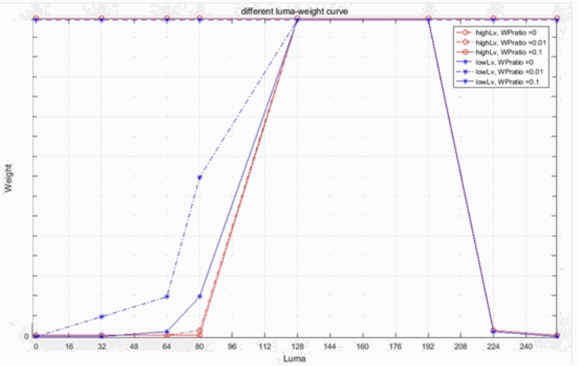
English source figure, PDF p.20, #91.
It can be seen from the figure that when the proportion of suitable luminance white points is large, the weight assigned to the suitable luminance interval (such as the y range 80-224) is larger, while the weight of other dark or bright areas is smaller.
Corresponds to the autoPara.wpDiffLumaWeight parameter in JSON
| Name | Description |
|---|---|
| enable | The switch value enabled by this function is 0 or 1 0 is not enabled 1 Enable |
| wpDiffWeiEnableTh | The feature enablement also requires the threshold condition to be met |
| wpDiffWeiEnableTh.wpDiffWeiNoTh | The number of white points is greater than this threshold before the value range [0,1] |
| wpDiffWeiEnableTh.wpDiffWeiLvValueTh | The ambient brightness is greater than this threshold to enable the value range [0-2555000] |
| wpDiffwei_y | The brightness segmentation of the white point brightness histogram, nine points divided into 8 bins value range [0,255] Note: It is not recommended to adjust the difference between the two adjacent components to the power of 2 |
| perfectBinConf | Specify which bin’s white point on the white point brightness histogram is a white point with high confidence, that is, specify the appropriate brightness , each component corresponds to a bin value range of 0 or 1 0 0 white point with low confidence 1 white point with high confidence |
| wpDiffWeiLvTh | The two components correspond to the ambient brightness of wpDiffWeiLvTh0 and the value range of wpDiffWeiLvTh1 [0-2555000] |
| wpDiffWeightLvSet | Different white point ratios with different confidence levels under different ambient brightness can be configured with different curves, and the actual situation is linearly interpolated by these curves |
| wpDiffWeightLvSet_len | Number of ambient brightness |
| wpDiffWeightLvSet.LvValue | Ambient brightness value |
| wpDiffWeightLvSet.ratioSet | When the ambient brightness is wpDiffWeightLvSet.LvValue, different white point ratios with high confidence can be configured with different curves |
| wpDiffWeightLvSet.ratioSet_len | Number of white dots with high credibility |
| wpDiffWeightLvSet.ratioSet.ratioValue | Percentage of white dots with high confidence |
| wpDiffWeightLvSet.ratioSet.weight | When the ambient brightness is wpDiffWeightLvSet.LvValue, and the proportion of white points with high confidence is wpDiffWeightLvSet.ratioSet.ratioValue, the brightness weight corresponds to a bin value range for each component [0,1] |
2.2.11.8 Chunking weights
The white point of different blocks can be configured with different weights, which can be configured and used according to actual applications, and it is not recommended to use them without special requirements
| Name | Description |
|---|---|
| wpDiffBlkWeiEnable | The switch value enabled by this function is 0 or 1 0 is not enabled 1 Enable |
| wpDiffBlkWeight | 15*15 blocks, the weight of each block takes the range [0-63], integer |
2.2.12 AWB policy
2.2.12.1 The partition policy computes WBGain
English source figure, PDF p.22, #101.
Figure AWB Partition Policy Calculation WBGain Illustration
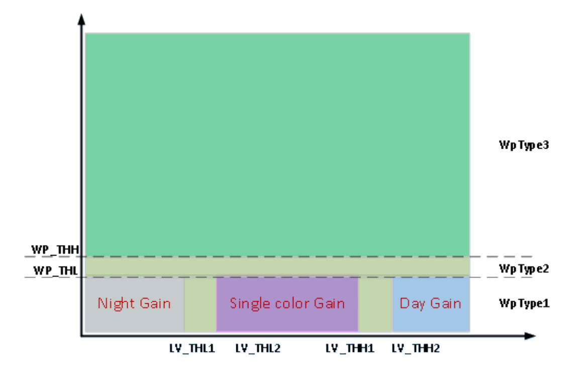
The ambient luminance-white point number space is partitioned so that different intervals use different methods to calculate the white balance gain. Supplementary ambient brightness meaning: if the average brightness of the scene is 255 (maximum) under 1x exposure gain and 1ms exposure integration time, the ambient brightness is 255000; A higher value indicates a brighter environment.
2.2.12.1.1 (1) Interpartition parameters
The interpartition parameter corresponds to the autoExtPara.division structure in JSON
| Name | Description |
|---|---|
| lumaValThLow | The ambient brightness threshold on the graph LV_THL1 range 0-255000 |
| lumaValThLow2 | The ambient brightness threshold on the graph LV_THL2 value range 0-255000 |
| lumaValThHigh | The ambient brightness threshold on the graph LV_THH1 range 0-255000 |
| lumaValThHigh2 | The ambient brightness threshold on the graph LV_THH2 range 0-255000 |
| wpNumTh | Different ambient brightness can be configured with different threshold WP_THL and WP_THH on the graph, and the actual threshold can be obtained by linear interpolation of these configurations |
| wpNumTh.lumaValue | The ambient brightness range is 0-255000 |
| wpNumTh.low | The threshold of the number of white spots on the figure WP_THL the value range 0-100000, and the actual number of white spots is compared with WP_THL/100000 *totalPixe, where totalPixel = wight * height /ds_w/ds_h, the image width and height are wight, height, and the downsampling multiples of horizontal and vertical directions are ds_w, ds_h |
| wpNumTh.high | The threshold for the number of white spots on the figure WP_THH the value range 0-100000, and the actual number of white spots and WP_THH /100000 *totalPixel comparison |
2.2.12.1.2 (2)Policy wbgain related parameters
According to the above threshold, the ambient luminance-white point number space is partitioned, and the method of calculating the white balance gain in different intervals is:
① The wbgain in WPType3 is related to the white point statistical gain (StaGain_i) of different light sources, the wbgain (DayGain_i) of the bright environment, and the wbgain (NightGain) of the dark environment, the StaGain_i weight is staWeigthSet, and the weight of the DayGain_i is 100-staWeigthSet. NightGain is weighted tempWeigth, which will be described in more detail later.
② WPType2 is the transition zone, obtained by mixing WPType3 and WPType1’s wbgain;
③ WPType1中的wbgain:
If it is the first frame, it may be a fixed NightGain or DayGain, or it may be a WBGain calculated by a simple color algorithm, which is determined by the interval of ambient brightness; Otherwise, it is the wbgain weighted of the previous frames
Corresponding to the parameters in JSON,
① DayGain
| Name | Description |
|---|---|
| defaultDayGainLow | The recommended range of WBGAIN in particularly bright sunlight is [0.5-7.9] |
| defaultDayGainHigh | The recommended WBGAIN value range in ordinary sunlight [0.5-7.9] |
| dayGainLvThSet | Represents dayGainLvThSet_THL and dayGainLvThSet_THH, corresponding to defaultDayGainLow and defaultDayGainHigh, respectively. Different light sources can have different configuration values [0-255000] |
| staWeight | The weight of the wbgain in WPType3 when calculating the StaGain_i. Different weights correspond to different StaGain_ weights at different brightness, corresponding to LvMatrix in JSON. The weight of the DayGain_i is 100- staWeigthSet. Different light sources can have different configurations. In general, the weight of StaGain is 100 is the best, for outdoor blue sky reddish scenes, you can configure defaultDayGainLow to d65 as standard wbgain, defaultDayGainHigh to d50 as standard wbgain, and reduce and change the staWeigth value under the brightness of the scene to improve the value [0-100] |
According to the ambient brightness, dayGainLvThSet, defaultDayGainLow, and defaultDayGainHigh, the DayGain_i of different light sources can be obtained by linear interpolation. The weights of the light sources described later are given DayGain in the WPType1 interval.
② NightGain
| Name | Description |
|---|---|
| defaultNightGain | That is, the NightGain described above, the recommended wbgain value range when the ambient brightness is low [0.5-7.9] |
| defaultNightGainWeight | The weight of NightGain when calculating wbgain in WPType3 corresponds to different weights at different brightness, corresponding to lumaValueMatrix in JSON. The value range is 0-100 |
③ SingleColorGain(singleColorProcess)
The function of realizing large-area simple color white balance selects colors and WBGain from the configured color collection and light source collection based on scene information. At present, the colors that can be recognized by the default calibration parameters are red, green, blue, yellow, and purple. You can add or delete the color set to be selected (colorBlock) according to the actual application, and adjust the light source set to be selected (lsUsedForEstimation), the tool does not support this function, corresponding to autoExtPara.singleColorGain in JSON
| Name | Description |
|---|---|
| enable | The switch value enabled by this function is 0 or 1 0 is not enabled 1 Enable |
| colorBlock | A collection of colors to select, generated by the tool |
| colorBlock_len | The total number of colors in the colorBlock collection |
| colorBlock.index | Color index, mark the color block used in calibration, modification has no effect on the effect, the value range 1-24 The calibration tool selects 13, 14, 15, 16, 5, 10 |
| colorBlock.meanC | The average chromaticity value of the color in LCH space |
| colorBlock.meanH | The average tonal value of the color in LCH space |
| lsUsedForEstimation | A collection of lights to select, generated by the tool |
| lsUsedForEstimation_len | The total number of lights in the lsUsedForEstimation collection |
| lsUsedForEstimation.name | Light source name |
| lsUsedForEstimation.RGain | The value of the red channel white balance gain of this light source is greater than 0, decimal |
| lsUsedForEstimation.BGain | The value of the blue channel white balance gain of this light source is greater than 0, decimal |
| alpha | The H weight of the LCH space can be used with the default value, and the value range [0.0-1.0] can be adjusted without adjusting the value range |
④ If the previous frames have a white balance gain, the wbgain weighted by the previous frames is used as the white balance gain of WpType3
| Name | Description |
|---|---|
| weightForNightGainCalc_len | Specifies that the first weightForNightGainCalc_len frames are used to weight any value, integer |
| weightForNightGainCalc | Specify the weight used for weighting the first few frames, the 0th position corresponds to the weight of the farthest frame, and the last position corresponds to the weight of the latest frame [0-100] |
2.2.12.1.3 (3) Calculate the relevant parameters of the light source weight
Probabilistic calculation parameters for different light sources in WpType3

English source figure, PDF p.26, #126.
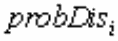
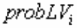
Prob_i = probLV_i * probDis_i * probWP_i
English source figure, PDF p.26, #127.
probDis_i
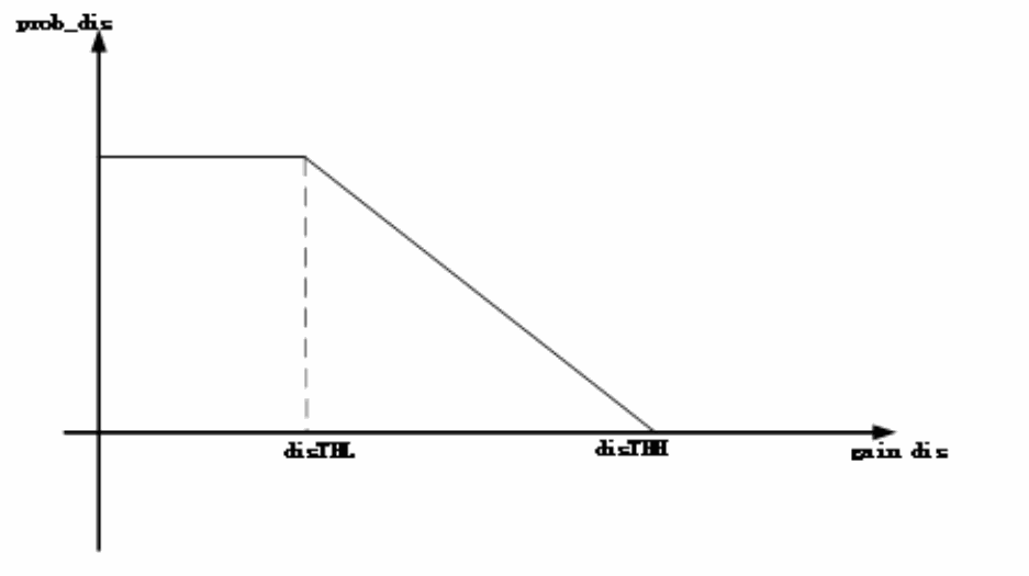
① Distance probability parameter
The Euclidean distance (gain_dis) from the wbgain of the previous frame to the standard wbgain of each light source is calculated according to the segmented straight line in the figure below.
English source figure, PDF p.26, #130.
Corresponds to the structure of autoExtPara.probCalcDis in JSON
| Name | Description |
|---|---|
| proDis_THL | The distance threshold disTHL on the graph takes the value range [0-4] |
| proDis_THH | The distance threshold disTHH on the graph takes the range [0-4] |
English source figure, PDF p.26, #133.
probLV_i
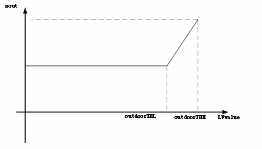
② Scene brightness probability parameters
The probability of the outdoor type of light source is pout, which is calculated from the luminance-pout curve of Figure 4-14
Indoor type light sources have a probability of pin = 1-pout
Light sources that cannot be strictly distinguished, such as PD50 = max(pout, pin)
English source figure, PDF p.27, #138.
The parameters in the corresponding JSON are as follows
| Name | Description |
|---|---|
| autoExtPara.probCalcLv.outdoorLumaValThLow | The ambient brightness threshold on the figure outdoorTHL takes the value range 0-255000 |
| autoExtPara.probCalcLv.outdoorLumaValThHigh | The ambient brightness threshold on the figure outdoorTHH takes the value range 0-255000 |
| autoPara.lightSources.doorType | Whether the light source is indoor or outdoor, different light sources have different configurations1 means indoor2 means between indoor and outdoor3 means outdoor |
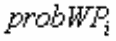
English source figure, PDF p.27, #141.
probWP_i
③ Scene White Point Number Probability parameter
Corresponds to the structure of autoExtPara.probCalcWp in JSON
| Name | Description |
|---|---|
| wpNumPercTh | When the number of white points of a light source is less than wpNumPercThtotalPixel, and the proportion of the number of white points to the number of white points of all light sources is less than wpNumPercTh2, the probability of the number of white points of the light source is 0, where totalPixel = wight height /ds_w/ds_h, the image width and height are wight, height, and the downsampling multiples of horizontal and vertical directions are ds_w, ds_h , respectivelyThe value range is 0-1 |
| wpNumPercTh2 | Ditto |
2.2.13 WBGain color adaptation adjustment
It is not recommended for the time being, corresponding to the structure of autoExtPara.chrAdpttAdj in JSON
| Name | Description |
|---|---|
| enable | The white balance corrected image is as consistent as possible with the color appearance perceived by the human eye, with an enable value of 0 or 1, which means not enabled and enabled |
| laCalcFactor | A factor that controls color adaptation at different brightnesses, with a default value of 40. |
| targetGain | Using wbgain to characterize the light source, adjusting the color appearance will be adjusted to the value range 0-4 under the light source, and the default value is d50 white balance gain |
2.2.14 WBGain range limit
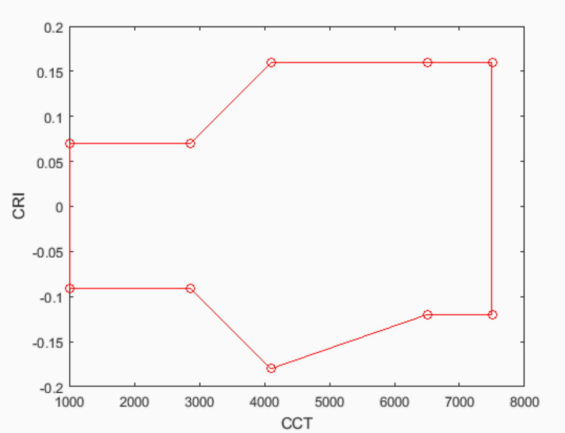
English source figure, PDF p.28, #149.
Limit the white balance gain to the area enclosed by the red line shown in the figure above, where the abscissa is the relative color temperature and the ordinate is the color rendering index, which are properties of the light source. Corresponds to the structure of autoExtPara.wbGainClip in JSON
| Name | Description |
|---|---|
| enable | The color temperature range limit enable value is 0 or 1, which means not enabled and enabled |
| cct | The upper and lower boundaries of the dot CCT coordinates corresponding to the enclosing area on the figure use the same CCT sampling coordinate value [1000-10000] |
| cri_bound_up | The lower boundary of the corresponding plot is a point in the corresponding plot, that is, cri0>=-cri_bound_up, otherwise the value is -1 to 1 |
| cri_bound_low | The upper boundary dot cri component of the corresponding area enclosed on the graph has a cri0<=cri_bound_low value -1 to 1 |
| cct_len/cri_bound_up_len/cri_bound_low_len | cct_len, cri_bound_up_len, cri_bound_low_len correspond to the lengths of cct, cri_bound_up, cri_bound_low, respectively, and these three should be equal |
In addition, the minimum color temperature of the outdoor light source can be limited, corresponding to the structure of autoExtPara.wbGainDaylightClip in JSON
| Name | Description |
|---|---|
| enable | The outdoor minimum color temperature limit enable value of 0 or 1, which means not enabled and enabled |
| outdoor_cct_min | The minimum outdoor color temperature is not limited |
If wbGainClip.eanble = 1, the scene is (cct0, cri0), if cct0 exceeds the left (right) boundary, the output cct0 will be forced to set to the value of the left (right) boundary; If cri0<-cri_bound_up, the output is cri0=-cri_bound_up; If cri0 >cri_bound_low, the output is cri0=cri_bound_low;
If wbGainDaylightClip.enable= 1 and the scene is an outdoor scene, if cct0 >outdoor_cct_min, output cct0=outdoor_cct_min.
2.2.15 WBGain hue adjustment
Corresponds to the structure of autoExtPara.wbGainAdjust in JSON
| Name | Description |
|---|---|
| enable | The value of tone adjustment enabled is 0 or 1, which means not enabled and enabled |
| lutAll | Different ambient brightness can be configured with different output color temperature meters |
| lutAll_len | Specify the number of color temperature tables |
| lutAll.lumaValue | The ambient brightness ranges from 0 to 255000 |
| lutAll.ct_grid_num | There is no limit to the number of sampling points for the color temperature of the input color temperature table |
| lutAll.ct_in_range | The range of color temperature in the input color temperature table is not limited to |
| lutAll.cri_grid_num | There is no limit to the number of sampling points for the color rendering index of the input color temperature table |
| lutAll.cri_in_range | The range of the color rendering index of the input color temperature table is not limited to |
| lutAll.ct_out | As shown in the tool interface figure below, the ct value of each dot is from left to right (the tone is from cold to warm), that is, the value range of CT from small to large is 0-255000 |
| lutAll.cri_out | As shown in the tool interface diagram below, the CRI of each dot is from bottom to top (the hue is from purple to green), that is, the CRI from negative to positive is not limited to |
| lutAll.ct_in_range_len/ lutAll.cri_in_range_len/lutAll.cri_out_len/lutAll.cri_out | Represents the number of points in the 2D mesh in the following tool interface diagram, which is equal and lutAll.ct_grid_num*lutAll.cri_grid_num |
The current JSON version of the tool does not support the adjustment function.
When the color temperature is not adjusted ct_out the 2D grid corresponding to the cri_out is shown below, and the rectangular areas specified by the ct_in_range and cri_in_range are sampled at ct_grid_num and cri_grid_num intervals in the horizontal and vertical directions, respectively, and the sampling points correspond to the dots in the following figure. ct_out stores the ct coordinates of all the dots, cri_out stores the ordinates of all the dots.
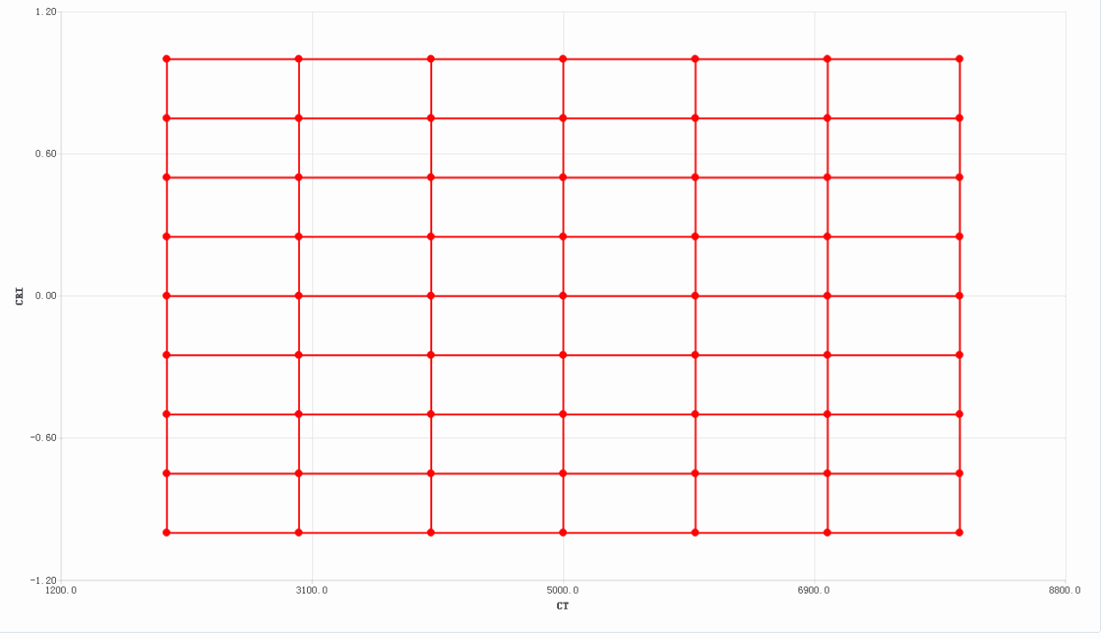
English source figure, PDF p.31, #161.
For adjustments to the overall color style:
(1) If you want to warm up the color tone with a color temperature of 2000k, select the CT Line Only mode adjustment table as shown below, move the mouse near any dot of cct=2000, click and drag to the right. After application, the input is 2000k-2391k, and all will be adjusted to 2391k.
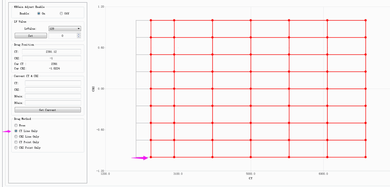
English source figure, PDF p.31, #164.
(2) If you want to cool down all the color tones, select the CT Line Only mode adjustment table as shown below, move the mouse over any of the dots of different CCTs, click and drag to the left until all the color tones are shifted to the left.
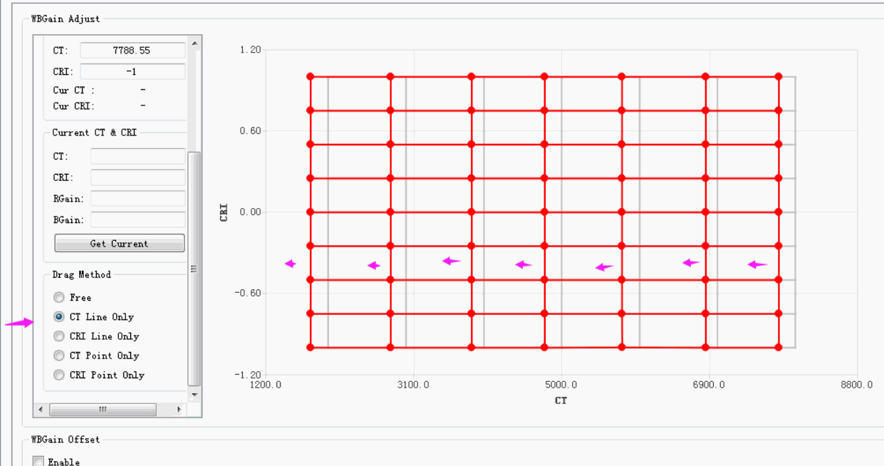
English source figure, PDF p.32, #166.
(3) If you want to turn all CRI tones of 0.5 to purple, select CRILine ONLY mode to adjust the table as shown below, move the mouse near any dot of CRI=0.5, click and drag down. If you drag it upwards, you get a greenish tint.
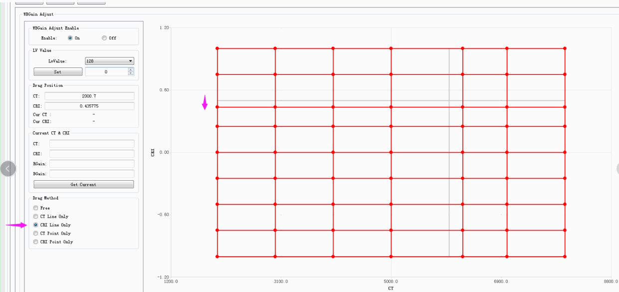
English source figure, PDF p.32, #168.
The tonal adjustment effect is as follows (the middle is the original image, with green, purple, blue, and red tones on the top, bottom, left, and right respectively)
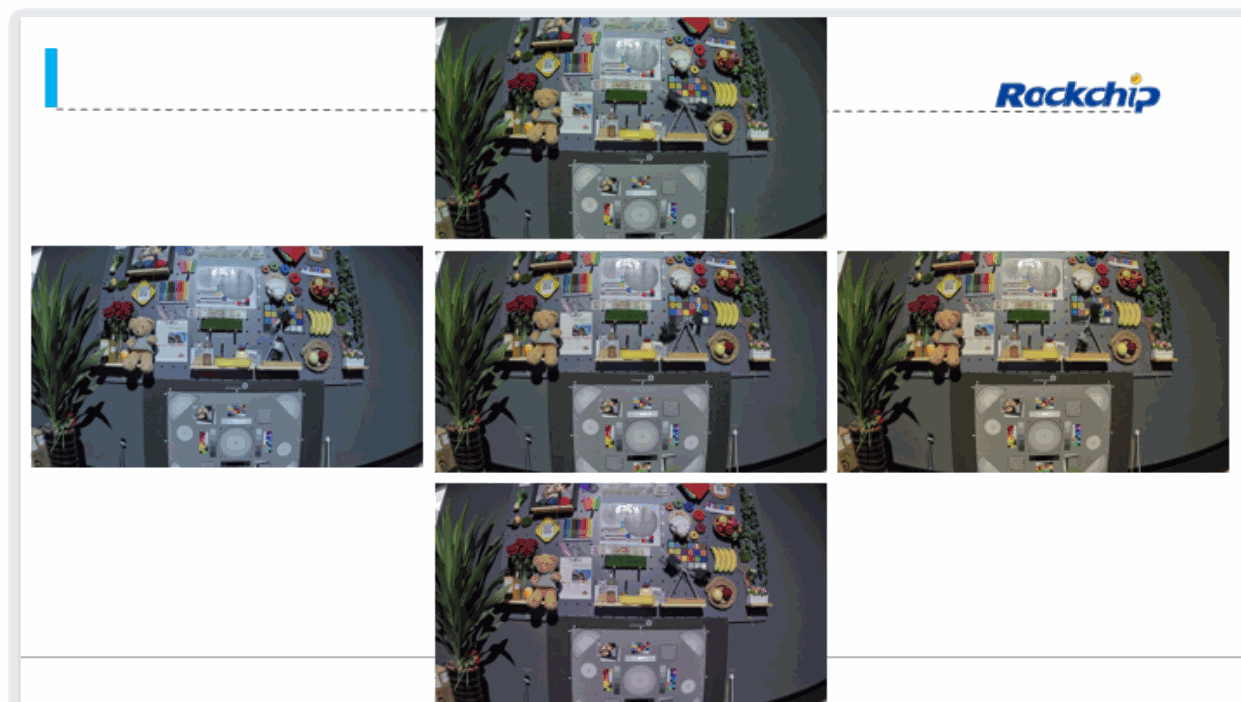
English source figure, PDF p.33, #170.
In addition, the 2D table can easily adjust the local wbgain without affecting other scenes, at this time, you can choose the free mode to adjust in any direction, and move the coordinates of the four vertices of the rectangle where it is located to adjust the output wbgain.
2.2.16 wbGain offset
Corresponds to the structure of autoExtPara.wbGainOffset in JSON
| Name | Description |
|---|---|
| enable | The enable switch takes a value of 0 or 1, which means no enable and enable |
| offset | The offset range of the corresponding R GR GB B channel is determined by the addition of wbgain and offset, that is, the range of wbgain and offset is [0,4] ( ISP21) after adding, and the range of wbgain and offset is in the range of [0,8] (other) |
2.2.17 remosaic sensor configuration
When other forms of sensor raw are converted to bayer raw by interpolation, it is necessary to multiply the wbgain effect first, and then there is no inverse wbgain calculation, in order to adapt to the configuration used by the current awb algorithm, corresponding to the structure of autoExtPara.remosaicCfg in JSON
| Name | Description |
|---|---|
| enable | The enable switch takes a value of 0 or 1, which means that the sensor that is not enabled and the bayer arrangement is enabled does not need to be enabled |
| sensorWbGain | The wbgain multiplied by interpolation, corresponding to the R GR GB B channel value range, see the sensor’s documentation |
| applyInvWbGainEnable | Whether to switch inverse wbgain before raw awb statistics, that is, divide by sensorWbGain value 0 or 1, respectively, means not enabled, enable |
2.2.18 WBGain smoothing
It is used to calculate the weight of the white balance gain of the previous frame (wbGainDampFactor), and realize the smoothing of wbgain change by weighting the previous frame and the current frame wbgain. If you want to adjust wbgain stability, increase dFMin, dFMax, but the convergence speed will be slower; If you want to speed up the convergence speed reduce dFMin, dFMax, but then wbgain may jump.
The wbGainDampFactor calculation logic is: wbGainDampFactor is stable in dFMax when the ambient brightness changes small, and wbGainDampFactor approaches the dFMin direction when the ambient brightness changes abruptly, that is, the weight of the current frame is increasing, so that wbgain keeps up with the changes in the environment as much as possible and accelerates the convergence process. The specific code is as follows:
if (varianceLuma > LvVarTh) {
*wbGainDampFactor -= dFStep;
}
else {
*wbGainDampFactor += dFStep;
}
if (*wbGainDampFactor < dFMin) {
*wbGainDampFactor = dFMin;
}
else if (*wbGainDampFactor > dFMax) {
*wbGainDampFactor = dFMax;
}
Corresponds to the structure of autoExtPara.dampFactor in JSON
| Name | Description |
|---|---|
| dFStep | The step size of the wbGainDampFactor change ranges from 0-1 |
| dFMin | The minimum value of wbGainDampFactor is in the range 0-1 |
| dFMax | The maximum value of wbGainDampFactor ranges from 0-1 |
| LvIIRsize | Record several frames of ambient brightness in the range of 0-255 |
| LvVarTh | It is used to determine whether wbGainDampFactor wants to change the ambient luminance variance threshold in the range of 0-255000 |
2.2.19 Other
2.2.19.1 tolerance
Used to control the update of wbgain, different thresholds (toleranceValue) can be configured under different ambient brightness (lumaValue). When the average of the difference in white balance gain (all channels) calculated by the AWB policy over several frames is less than this threshold, wbgain uses the value of the previous frame, where the number of frames is configured by the weightForNightGainCalc_len. Corresponds to the structure of autoExtPara.tolerance in JSON
| Name | Description |
|---|---|
| lumaValue | Ambient brightness, value range [0-255000], refer to the lumaValueMatrix later to configure |
| toleranceValue | Threshold, value range [0-1] |
| lumaValue_len/toleranceValue_len | Equal, the number of corresponding configurations has an unlimited value range |
2.2.19.2 runInterval
It is used to control the automatic white balance every few frames, and different frame times (intervalValue) can be configured under different ambient brightness (lumaValue). Corresponds to the structure of autoExtPara.runInterval in JSON
| Name | Description |
|---|---|
| lumaValue | Ambient brightness, value range [0-255000], refer to the lumaValueMatrix later to configure |
| intervalValue | Number of frames, value range [0-255] |
| lumaValue_len/intervalValue_len | Equal, the number of corresponding configurations has an unlimited value range |
2.2.19.3 lumaValueMatrix
Corresponds to the array of autoExtPara.lumaValueMatrix in JSON
| Name | Description |
|---|---|
| lumaValueMatrix | The ambient brightness is divided into 15 levels, and the starting ambient brightness value of each level ranges from 0-300000 |
2.2.19.4 White balance convergence judgment
Corresponds to the structure of autoExtPara.converged in JSON
| Name | Description |
|---|---|
| varThforUnDamp | White balance convergence threshold; White balance convergence is considered when the average of the difference in white balance gain (all channels) calculated by the AWB policy within a few frames is less than the threshold varThforUnDamp, and the average difference in the smoothed white balance gain (all channels) within several frames is less than varThforDamp. The frame number is specified by the weightForNightGainCalc_len configuration in the range of 0.0-1; the recommended value is 0.06 |
| varThforDamp | The meaning and range of parameters are the same as the recommended value 0.03 |
2.2.19.5 Selection parameters for white dots in the box, large box, and attachment box
Corresponds to JSON’s autoExtPara.xyRegionStableSelection node
| Name | Description |
|---|---|
| enable | Medium box, large frame, additional white dot box select the function switch with stable result |
| xyTypeListSize | xyRegionSize and LvVarTh are used to stabilize the results of the marquee, xyTypeListSize frames with more votes as the final result, and LvIIRsize (see WBGain Smoothing) The variance of the ambient brightness in the frame is less than varianceLumaTh, the result of the marquee is not updated, that is, what box is used in the previous frame, and this box is always used in the next frame. The value range is 0-1000; |
| varianceLumaTh | See description in the line above; The value range is 0-1000; |
| wpNumTh | Configure configurations that vary with ambient brightness, from which thresholds are linearly interpolated |
| wpNumTh.lumaValue | ambient brightness; The value range is 0-255000 |
| wpNumTh.forBigType | The number of white points and forBigType/100000*totalPixel are compared with the value range 0-100000 |
| wpNumTh.forExtraType | The actual number of white points and forExtraType/100000*totalPixel are compared with the value range 0-100000 |
xyRegionSize = 0 or varianceLumaTh= 0 applies the marquee result corresponding to the current frame information to each frame.
if(number of white dots in the middle frame> forBigType/100000*totalPixel){
Then the white point for calculating wbgain comes from the middle box
}else{
The white point for calculating wbgain comes from the large box
if(The number of white dots in the large box<=forExtraType/100000*totalPixel && The total number of white dots in the accessory white dot box > 0){
The white point for calculating wbgain comes from the additional white point box}
}
Concentrate:
(1) When the white point of calculating wbgain comes from the additional white point box, the parameter in the “Partition strategy calculation WBGain” section is invalid
2.3 Calibration
2.3.1 AWB calibration fundamentals
It mainly calibrates the white point conditions of Raw in XY, UV, YUV, simple color algorithm parameters and white balance gain under standard light sources
2.3.2 AWB calibration raw diagram requirements
When collecting RAW images, you need to prepare the following environment:
① Equipment: X-rite 24 color card, light box
② Adjust the exposure parameters so that the maximum value of the brightest white block in the color card is [150-240], the brighter the better in this range
③ The color card occupies more than 1/9 of the picture
Shoot the x-rite 24 color card under the A, CWF, D50, D65, D75, HZ, TL84 light source in turn, and the schematic diagram of the demosaic is as follows:
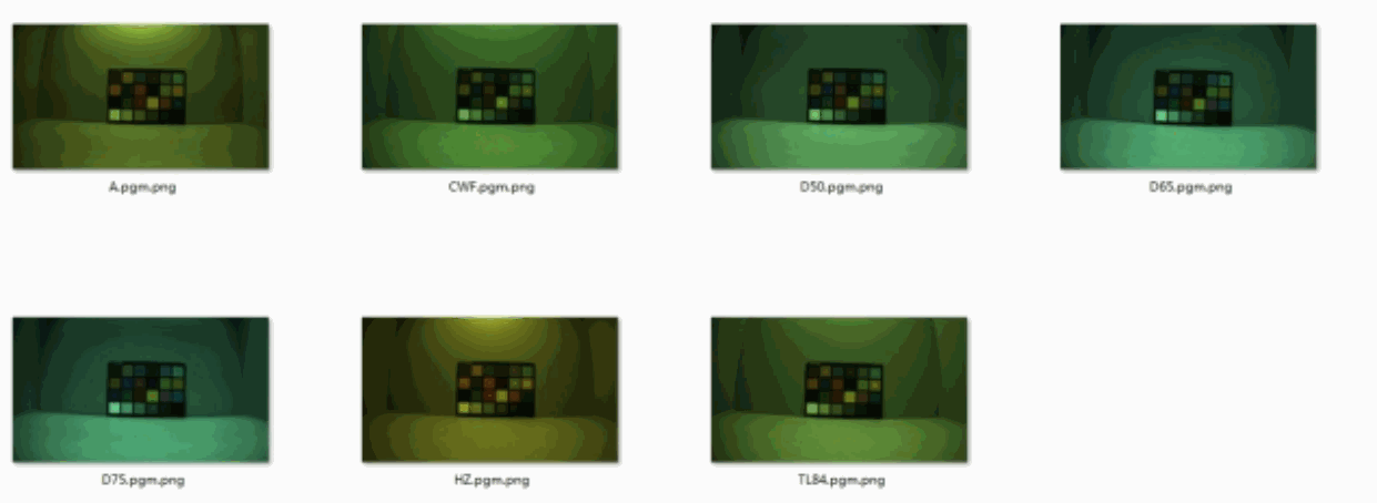
English source figure, PDF p.38, #231.
2.3.3 Description of the interface of the AWB calibration tool
(1)AWB main interface schematic
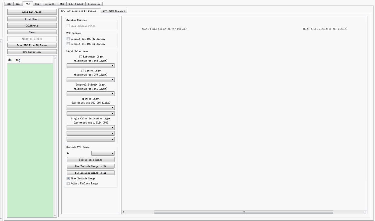
English source figure, PDF p.39, #234.
(2) When calibrating, the white point boundary of the UV and XY domains and the TH value of the YUV domain are mainly adjusted
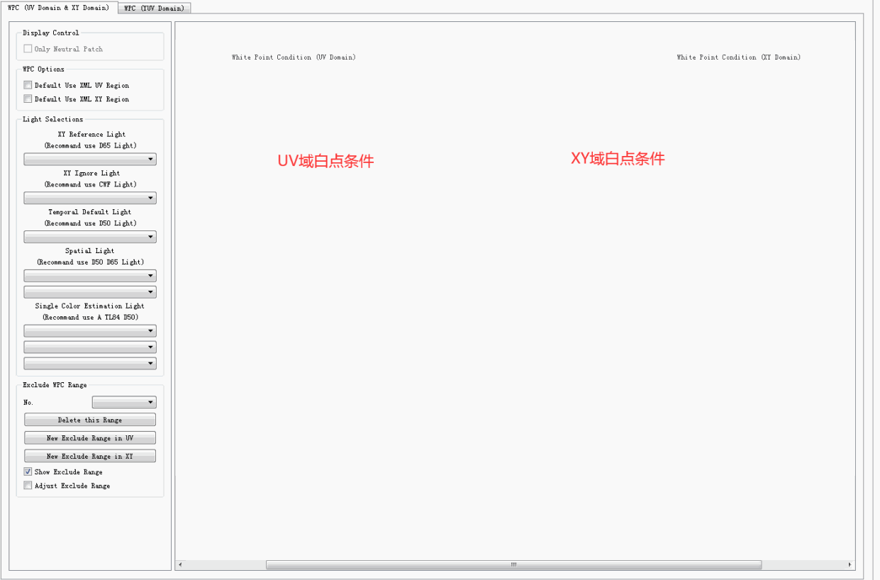
English source figure, PDF p.39, #236.
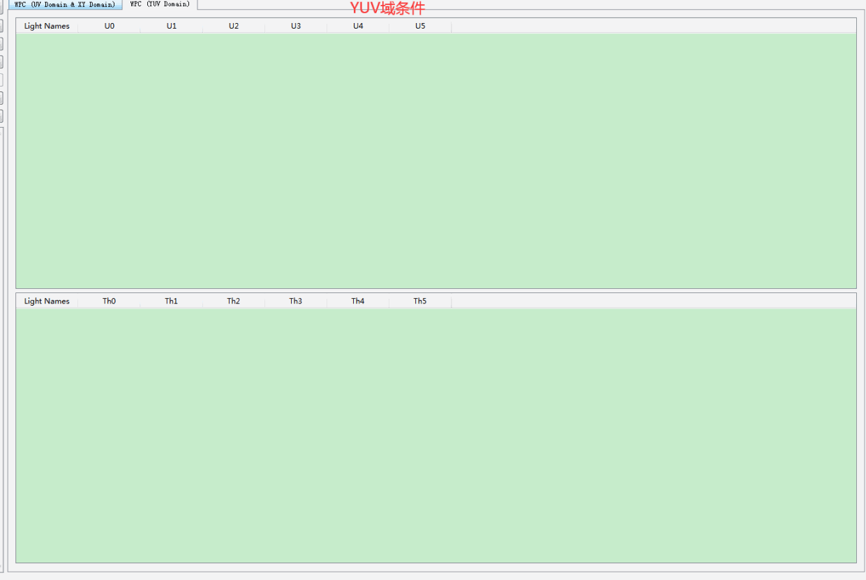
English source figure, PDF p.40, #237.
Operation instructions for adjusting the white point interval in the UV and XY domains a) Drag the corners of the white point condition with the mouse in the coordinate system to adjust the position and white point interval b) In the coordinate system, you can drag the entire white point interval by dragging the mouse over an empty area c) Use the scroll wheel to zoom in and out
(3) The Exclude WPC Range panel can be used to add non-white and additional light white point intervals.
(4) Clicking the “AWB Simulaton” button on “AWB Main Interface” will pop up the following interface. AWB Simulaton is used to detect white spots on raw plots and count white point gain and number
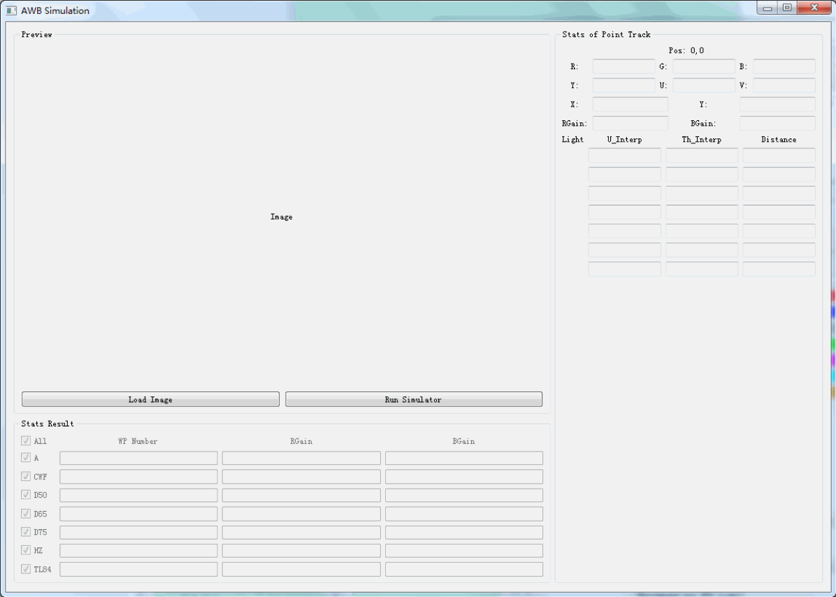
English source figure, PDF p.40, #241.
① LoadImage After importing the Raw image, as shown below, the white point information will be printed. The white point of different light sources is displayed in different colors. The number of white points in the middle and large boxes RGain and BGain are displayed in the Detected WP Number, RGain, BGain three text boxes
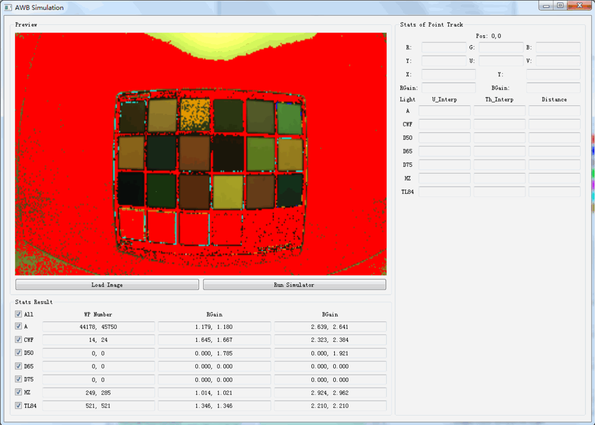
English source figure, PDF p.41, #243.
② Click anywhere in the image (shown below at the black arrow), which will be mapped to the UV domain white point conditional interface and the XY domain condition interface (small black squares), which is convenient to see whether the point falls within the white point interval; At the same time, the R G B U V X Y RGain BGain (red frame area) of the point is displayed, and the you and th after each light source are mapped in the yuv domain and the deviation distance from the standard white point (corresponding to the three columns of the green box area)
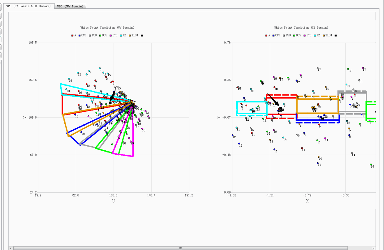
English source figure, PDF p.41, #245.
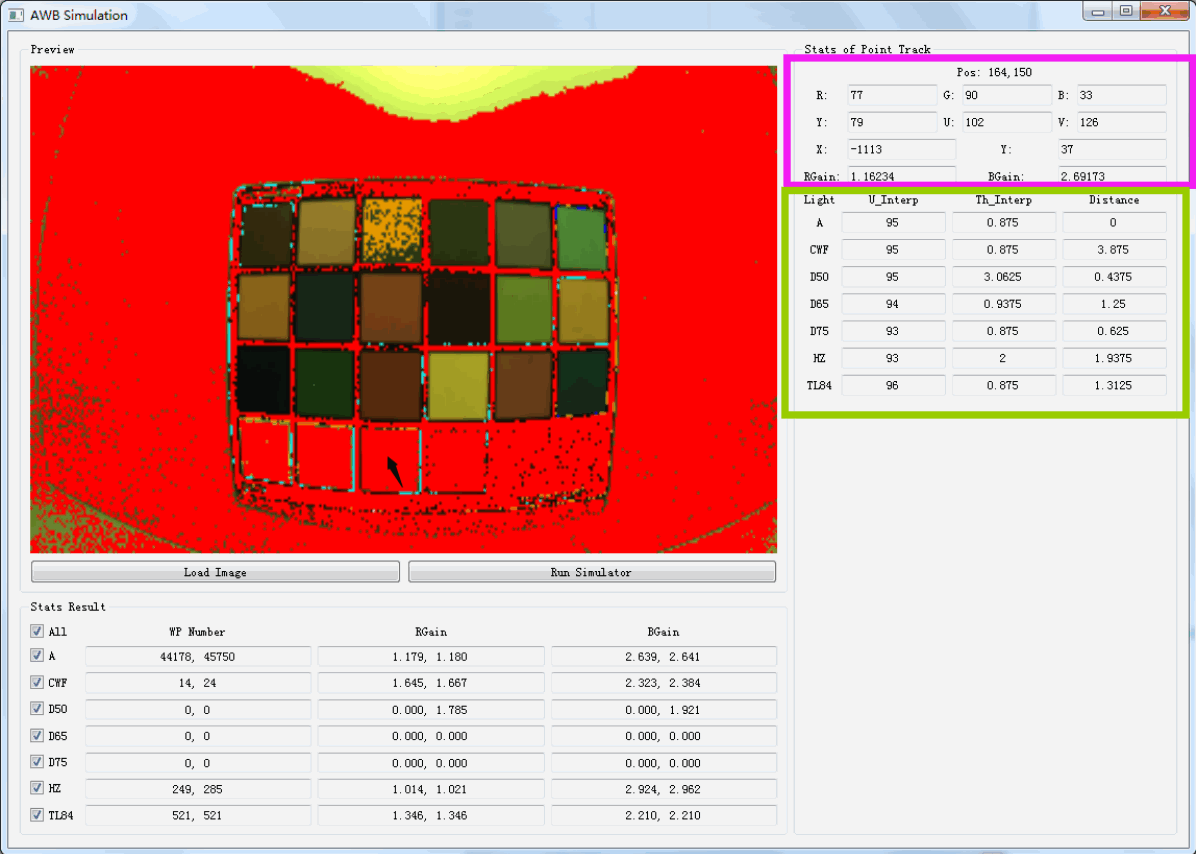
English source figure, PDF p.42, #246.
2.3.4 AWB calibration steps
(1) The calibration of BLC and LSC needs to be completed during AWB calibration
(2) Click Load Raw Files to import the raw map under A, CWF, D50, D65, D75, HZ, TL84 (it is recommended to calibrate the raw image of these seven light sources)
(3) Click Find Chart to identify the color card
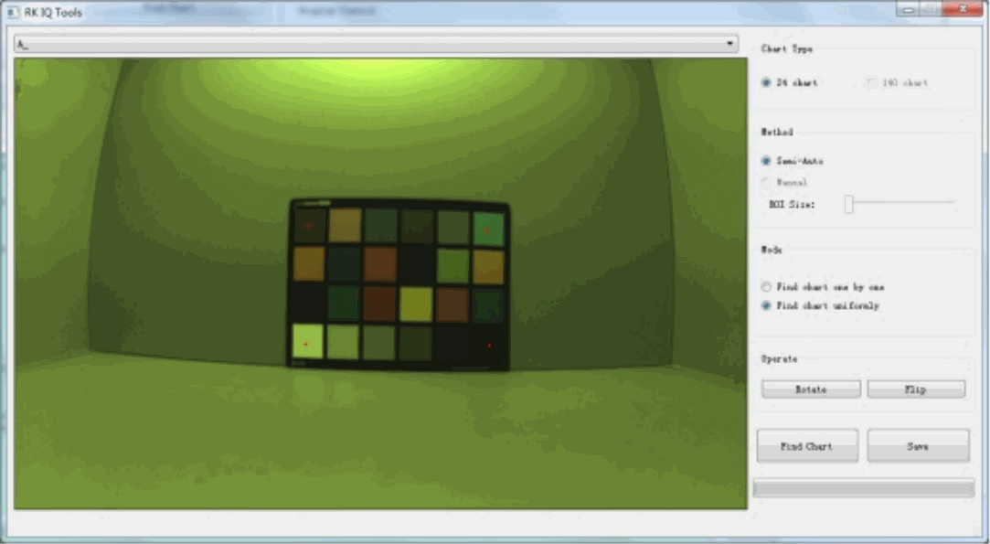
English source figure, PDF p.42, #251.
① Click Block 1, Block 6, Block 19, and then Block 20
② Clicking FindChart will batch identify the color card patches for all lights, as shown below (showing the white point detection result of the last light source)
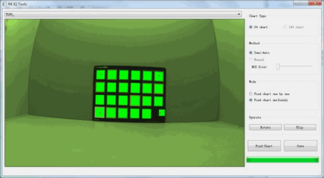
English source figure, PDF p.43, #254.
③ Select other light sources from the drop-down menu to confirm the correctness of the color block recognition, and find that only the last piece of TL84 is a little right, at this time, you only need to re-detect it separately, and select Find chart one by one in solid mode Repeat step 12 until the color card patch of TL84 is correctly identified, as shown below
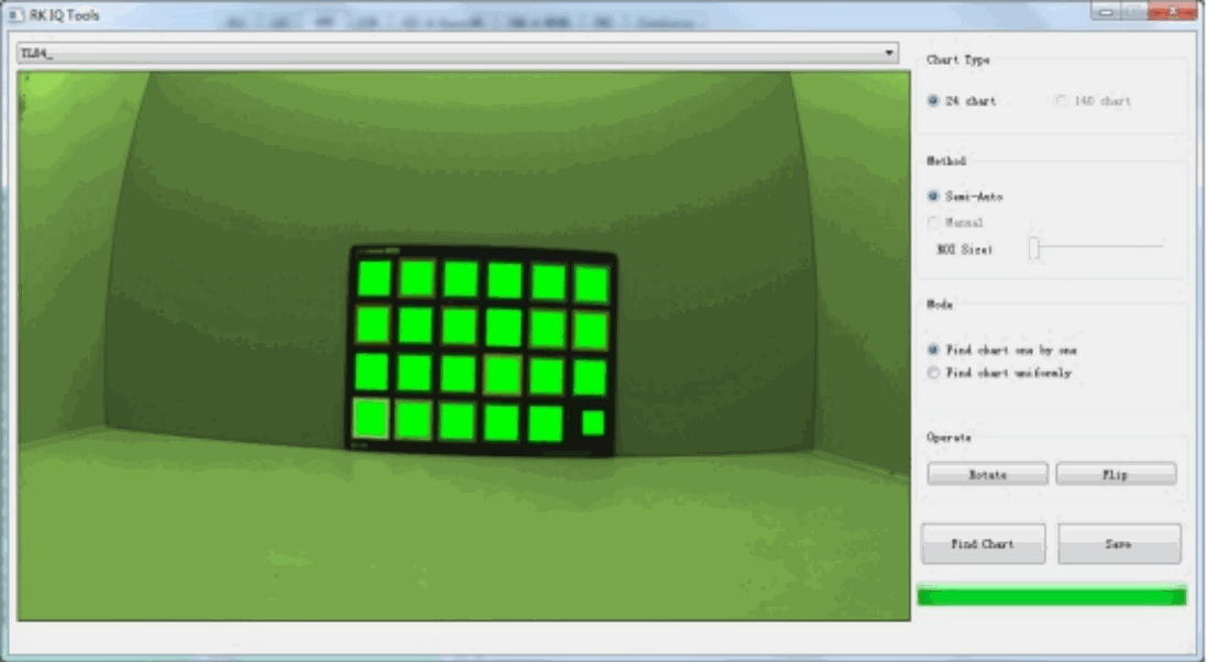
English source figure, PDF p.43, #256.
④ Click Save to complete the identification
(4) Click Calibrate to obtain the following initial white point condition and other parameters
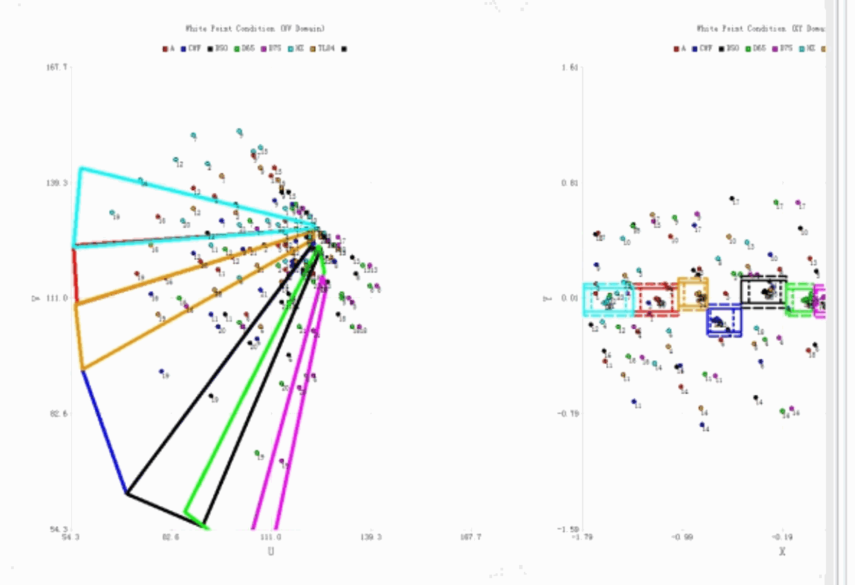
English source figure, PDF p.44, #259.
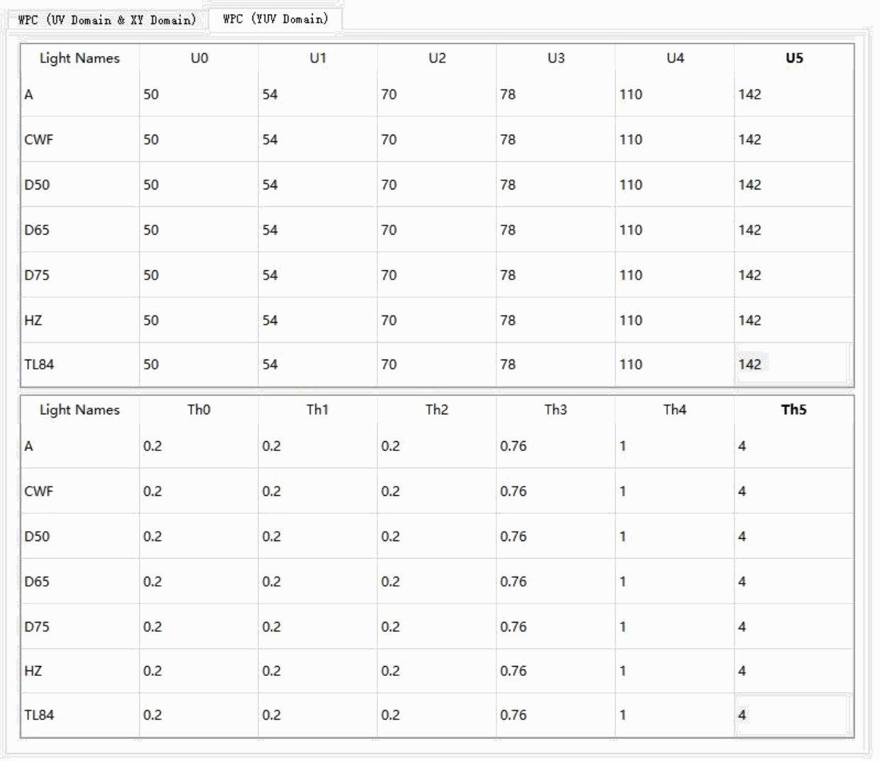
English source figure, PDF p.44, #260.
| Light | U0 | U1 | U2 | U3 | U4 | U5 |
|---|---|---|---|---|---|---|
| A | 50 | 54 | 70 | 78 | 110 | 142 |
| CWF | 50 | 54 | 70 | 78 | 110 | 142 |
| D50 | 50 | 54 | 70 | 78 | 110 | 142 |
| D65 | 50 | 54 | 70 | 78 | 110 | 142 |
| D75 | 50 | 54 | 70 | 78 | 110 | 142 |
| HZ | 50 | 54 | 70 | 78 | 110 | 142 |
| TL84 | 50 | 54 | 70 | 78 | 110 | 142 |
| Light | Th0 | Th1 | Th2 | Th3 | Th4 | Th5 |
|---|---|---|---|---|---|---|
| A | 0.2 | 0.2 | 0.2 | 0.76 | 1 | 4 |
| CWF | 0.2 | 0.2 | 0.2 | 0.76 | 1 | 4 |
| D50 | 0.2 | 0.2 | 0.2 | 0.76 | 1 | 4 |
| D65 | 0.2 | 0.2 | 0.2 | 0.76 | 1 | 4 |
| D75 | 0.2 | 0.2 | 0.2 | 0.76 | 1 | 4 |
| HZ | 0.2 | 0.2 | 0.2 | 0.76 | 1 | 4 |
| TL84 | 0.2 | 0.2 | 0.2 | 0.76 | 1 | 4 |
(5) Click AWB Simulaton to import the raw plots under A, CWF, D50, D65, D75, HZ, TL84 to view the accuracy of white point detection
(6) Modify the box of the UV domain or XY domain or the TH of YUV to make the white point detection of the color card under each light source more accurate
(7) Click Save
(8) Repeat (5) ~ (7) until the white point detection of each light source is reasonable.
(9) Precautions:
① Adjust the boundary so that the white point is inside the box and the non-white point is outside the box (generally cannot be done)
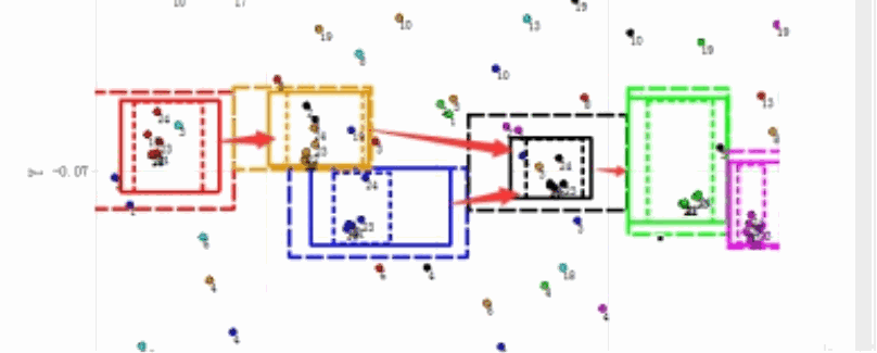
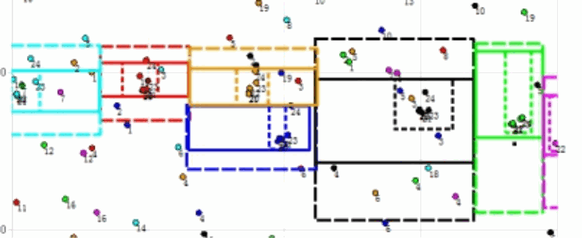
② The interval enclosed by the middle frame of the light source on all blackbody trajectories is continuous in the x direction (three linetypes represent boxes of three sizes, and there are no small boxes in the current version)
Error demonstration (the intervals of the large boxes are contiguous, but there is a gap between the middle boxes, as shown by the arrows below):
English source figure, PDF p.45, #269.
Correct demonstration:
English source figure, PDF p.45, #271.
③ A and hz light sources can be more compact in the Y direction of the XY domain, and the d50 d65XY domain can be relaxed in the Y direction
④ The medium and large frame intervals enclosed by light sources with similar color temperatures are continuous in the y direction (CWF and TL84)
⑤ All light sources are not disconnected in the interval enclosed by the UV domain
⑥ Different light source boundaries can overlap, but do not overlap in XY and UV space at the same time
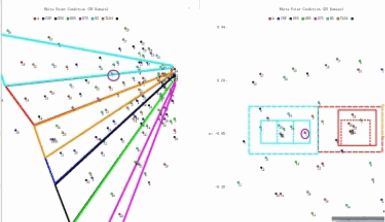
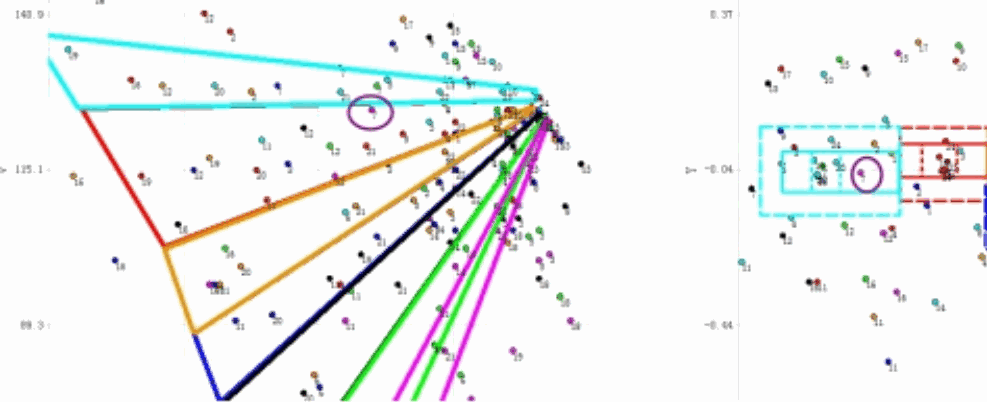
⑦ Divide the UV space with reference to XY space to exclude non-white spots
If the 7th block of the circled D75 light source falls in the hz range, it will be recognized as a white point
English source figure, PDF p.46, #278.
After readjustment, the 7th block B of the D75 light source is not in the same light source on xy and uv space and will not be recognized as a white point
English source figure, PDF p.46, #280.
⑧ When the non-white point falls in the white point interval of XY and UV, you can also exclude by reducing the TH of the YUV domain, or increasing the non-white point interval.
⑨ When the white point falls in the white point interval of XY and UV, but is still not a white point, it may be because it is excluded beyond the brightness range, or falls in the non-white point range, or because it is less than TH and does not fall in the white point interval of the YUV domain
2.3.5 Verification of AWB calibration parameters
The calibrated diagram is introduced in turn, and the white point detection is carried out, giving priority to ensuring a low missed detection rate and appropriately reducing the misinterpretation rate
Final white point condition:
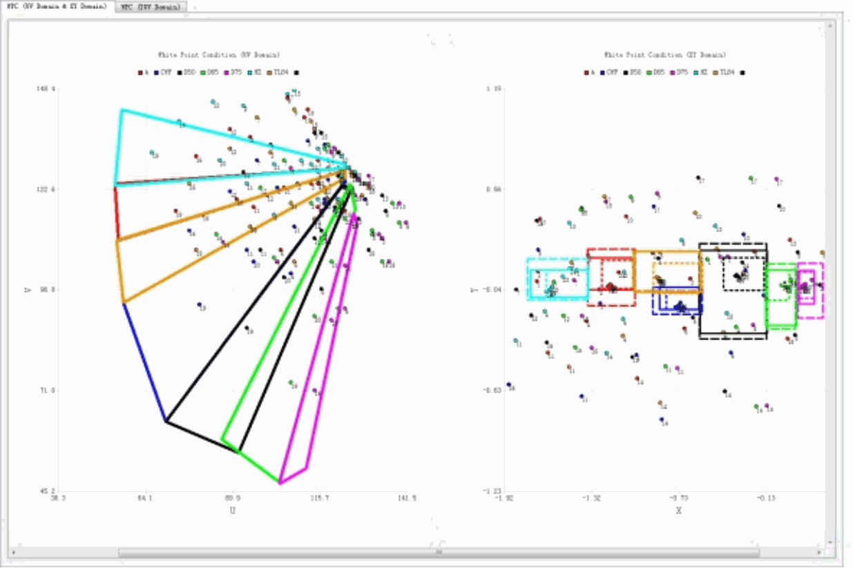
English source figure, PDF p.47, #286.
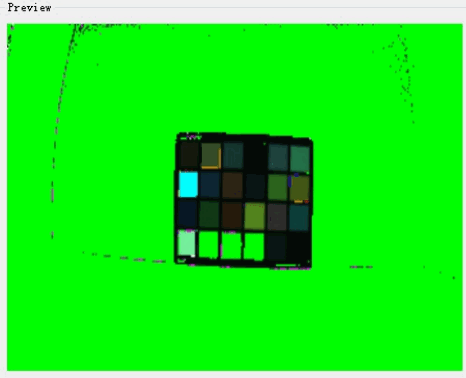
The white spot test results are:
A light
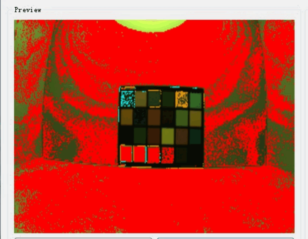
English source figure, PDF p.47, #289.
CWF:
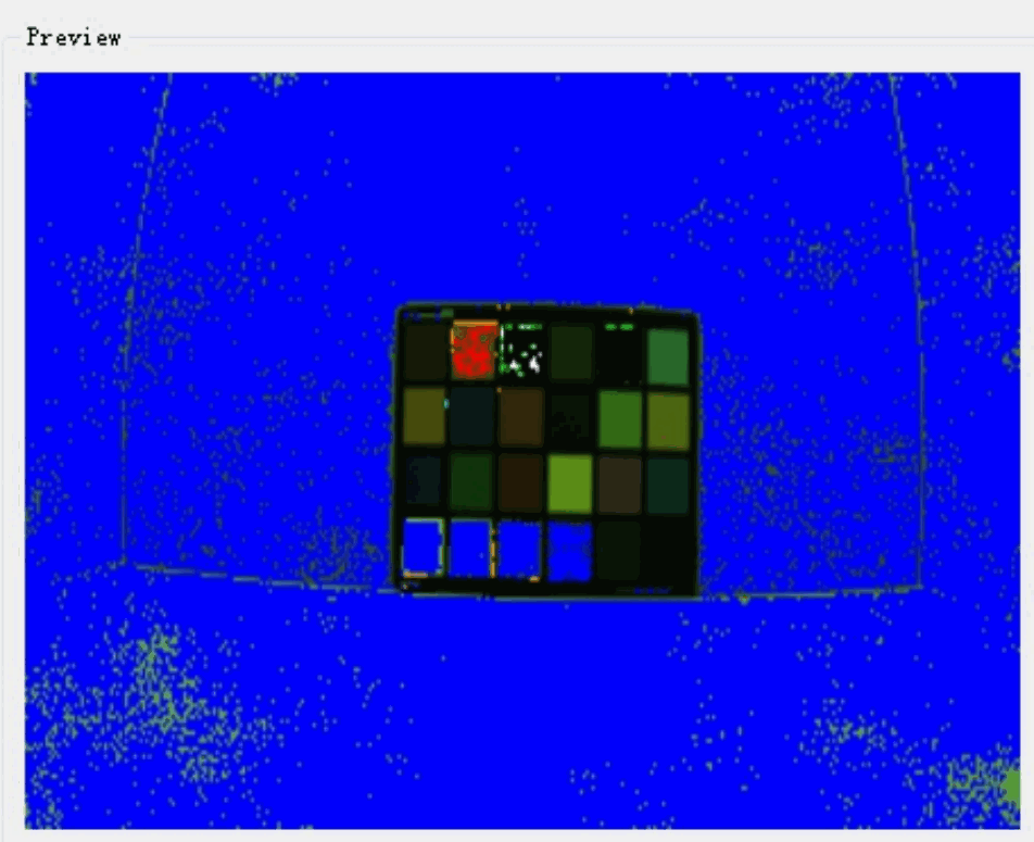
English source figure, PDF p.48, #291.
D50
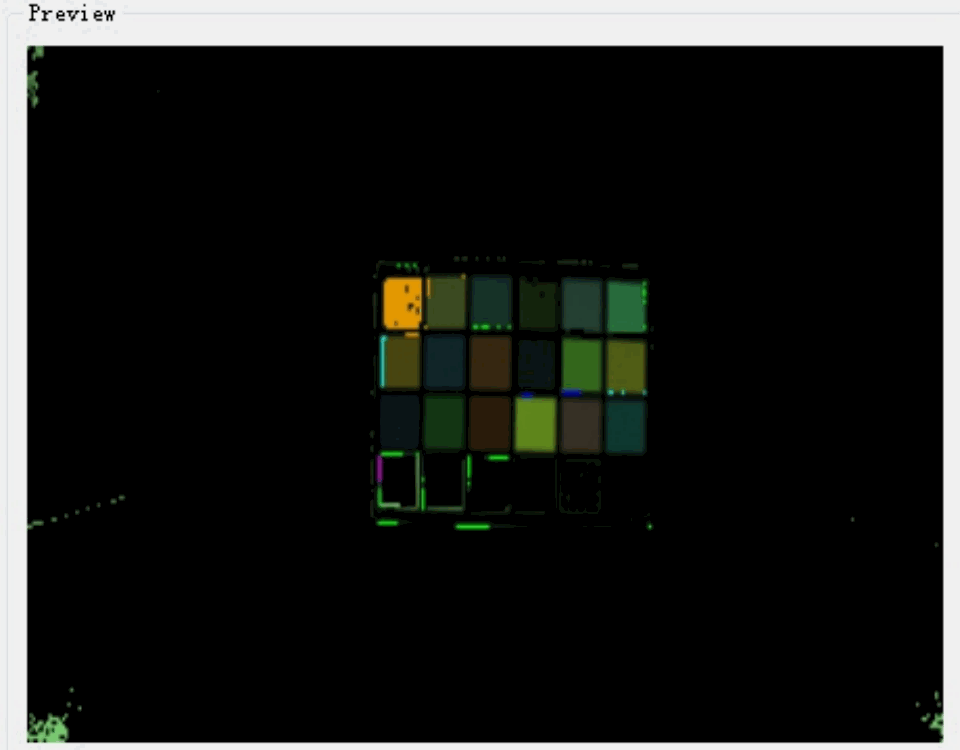
English source figure, PDF p.48, #293.
D65
English source figure, PDF p.49, #295.
D75
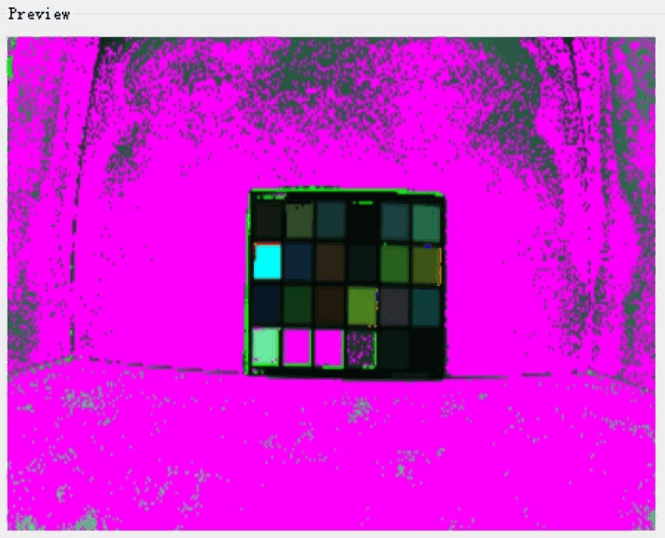
English source figure, PDF p.49, #297.
HZ
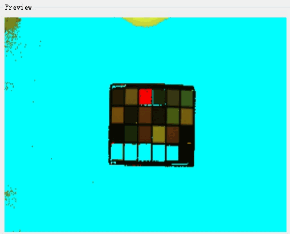
English source figure, PDF p.50, #299.
TL84
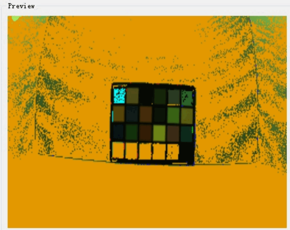
English source figure, PDF p.50, #301.
2.4 FAQ targeting
In order to solve the problem of white balance abnormality, it is usually necessary to catch the log and catch the raw to analyze the cause, and solve it by modifying the white point condition or modifying the policy parameters.
2.4.0.1 Capture logs and analyze
The awb log used for debug is export persist_camera_engine_log=0x2ff4
2.4.0.1.1 Interpretation of A
2.4.0.2 AWB log interpretation (take serial port or adb printed log as an example)
2.4.0.2.1 (1) Control and mode log

English source figure, PDF p.51, #309.
Transcription of legible screenshot text; source cropping is not reconstructed:
[AWB]:XCAM INFO (1782) rk_aiq_awb_algo_v201.cpp:1979: AwbInitV201: (enter)
[AWB]:XCAM INFO (1782) rk_aiq_awb_algo_v201.cpp:2040: AwbInitV201: (exit)
[AWB]:XCAM INFO (1782) rk_aiq_awb_algo_v201.cpp:2070: AwbPrepareV201: (enter)
[AWB]:XCAM INFO (1782) rk_aiq_awb_algo_v201.cpp:2148: hdr_working_mode(0), remosaic_cfg.enable (0)
[AWB]:XCAM INFO (1782) rk_aiq_awb_algo_v201.cpp:2149: AwbPrepareV201: (exit)
[AWB]:XCAM INFO (1782) rk_aiq_awb_itf.cpp:102: ---------------------------------------------frame_id (-1)---------------------------------------------
[AWB]:XCAM DEBUG rk_aiq_awb_algo_v201.cpp:2469: AwbReconfigV201: byPass: 0  mode( 0-manual 1-auto):1
[AWB]:XCAM INFO (1782) rk_aiq_awb_itf.cpp:250: processing awb_gain_algo (1.905082,1.000000,1.000000,1.978512)
[AWB]:XCAM INFO (1782) rk_aiq_awb_itf.cpp:102: ---------------------------------------------frame_id (0)---------------------------------------------
A hdr_working_mode of 0 indicates that it is currently in normal mode, otherwise it is HDR mode
A byPass of 0 indicates that white balance correction is enabled, and a value of 1 indicates that white balance correction is not enabled
A mode of 0 indicates that the current manual white balance mode is active, and a value of 1 indicates that the current automatic white balance mode is the current white balance mode
frame_id is the frame ID
processing awb_gain_algo The wbgain for the final output of this module
2.4.0.2.2 (2)The awb log level of export persist_camera_engine_log=0x2ff2 can be used for general problem localization

English source figure, PDF p.51, #317.
Transcription of legible screenshot text; source cropping is not reconstructed:
2: ---------------------------------------------frame_id (1)---------------------------------------------
68: ***1th calculate wbgain***
52: AwbGainClip, Input CCT : 5800.018555, CRI : -0.124677
09: AwbGainClip, Output CCT : 5800.018555, CRI : -0.124677
09: AwbGainAdjust2, Input CCT : 5800.018555, CRI : -0.124677
50: AwbGainAdjust2, Output CCT : 5800.018066, CRI : -0.124677
3:
7: wbgain_s5(after damping)(rggb):(2.146030,1.000000,1.000000,2.072558), awbConverged(0) ,LVValue(6054), WPType(3),df(0.75), frameChoose(0)
0: WPNo(normal,big):(203,208),valid wp number in standard light(187), valid wp number in extra light(0),
2: select white point range type (0-normal xy range,1-big xy range, 3-extra light) : 0, runInterval(0),tolerance(0.000000)
41:
0: processing awb_gain_algo (2.146030,1.000000,1.000000,2.072558)
AwbGainClip Input and output are wbgain-range limited input and output CCT and CRI, respectively;
AwbGainAdjust2Input and output CCT and CRI for tone-adjusted inputs and outputs, respectively.
wbgain_s5 is equal to the smoothed wbgain, which is generally equal to the processing awb_gain_algo; awbConverged of 0 or 1 is AWB unconverged and converged, respectively;
LVValue is ambient brightness;
WPType corresponds to the interval inside the policy partition;
df is the current smoothing coefficient wbGainDampFactor
frameChoose is 0 1 2 respectively indicates that short, medium, and long frames are used as input for AWB hardware statistics;
WPNo is the number of white points in the medium and large boxes
VAILD WP Number in Standard Light is the number of effective white points for all light sources
Select White Point Range Type 0 1 indicates that the current white point statistics are based on medium and large boxes, respectively
runInterval is how many frames to run
When the variance change with tolerance to wbgain is less than this value, wbgain will not be updated
2.4.0.2.3 (3)The AWB log level is export persist_camera_engine_log=0x2ff3, which can be used for white spot conditions and strategy problem positioning
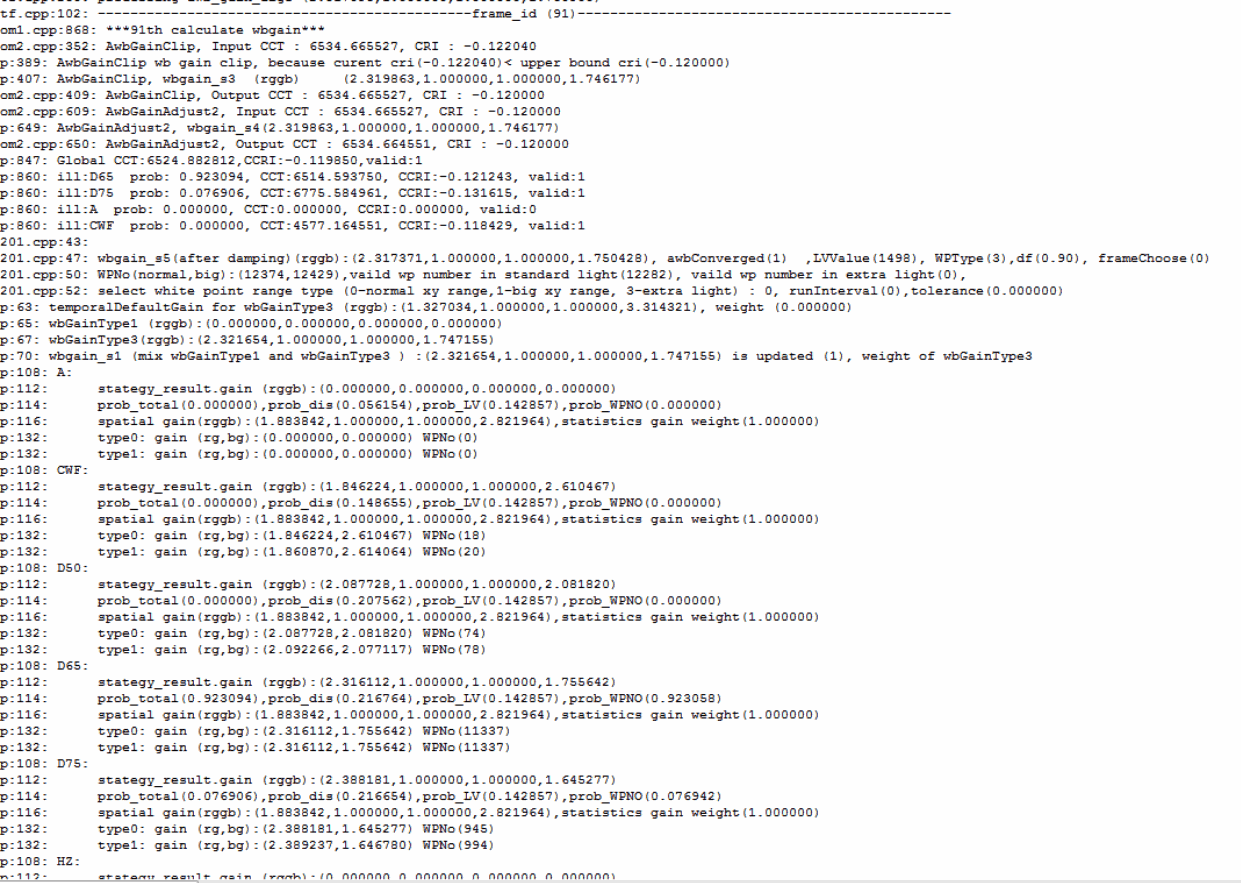
English source figure, PDF p.52, #332.
Transcription of legible screenshot text; source cropping is not reconstructed:
tf.cpp:102: ---------------------------------------------frame_id (91)---------------------------------------------
om1.cpp:868: ***91th calculate wbgain***
om2.cpp:352: AwbGainClip, Input CCT : 6534.665527, CRI : -0.122040
p:389: AwbGainClip wb gain clip, because current cri(-0.122040)< upper bound cri(-0.120000)
p:407: AwbGainClip, wbgain_s3 (rggb) (2.319863,1.000000,1.000000,1.746177)
om2.cpp:409: AwbGainClip, Output CCT : 6534.665527, CRI : -0.120000
om2.cpp:609: AwbGainAdjust2, Input CCT : 6534.665527, CRI : -0.120000
p:649: AwbGainAdjust2, wbgain_s4(2.319863,1.000000,1.000000,1.746177)
om2.cpp:650: AwbGainAdjust2, Output CCT : 6534.664551, CRI : -0.120000
p:847: Global CCT:6524.882812,CCRI:-0.119850,valid:1
p:860: ill:D65 prob: 0.923094, CCT:6514.593750, CCRI:-0.121243, valid:1
p:860: ill:D75 prob: 0.076906, CCT:6775.584961, CCRI:-0.131615, valid:1
p:860: ill:A prob: 0.000000, CCT:0.000000, CCRI:0.000000, valid:0
p:860: ill:CWF prob: 0.000000, CCT:4577.164551, CCRI:-0.118429, valid:1
201.cpp:43:
201.cpp:47: wbgain_s5(after damping)(rggb):(2.317371,1.000000,1.000000,1.750428), awbConverged(1) ,LVValue(1498), WPType(3),df(0.90), frameChoose(0)
201.cpp:50: WPNo(normal,big):(12374,12429),valid wp number in standard light(12282), valid wp number in extra light(0),
201.cpp:52: select white point range type (0-normal xy range,1-big xy range, 3-extra light) : 0, runInterval(0),tolerance(0.000000)
p:63: temporalDefaultGain for wbGainType3 (rggb):(1.327034,1.000000,1.000000,3.314321), weight (0.000000)
p:65: wbGainType1 (rggb):(0.000000,0.000000,0.000000,0.000000)
p:67: wbGainType3(rggb):(2.321654,1.000000,1.000000,1.747155)
p:70: wbgain_s1 (mix wbGainType1 and wbGainType3 ) :(2.321654,1.000000,1.000000,1.747155) is updated (1), weight of wbGainType3
p:108: A:
p:112:      stategy_result.gain (rggb):(0.000000,0.000000,0.000000,0.000000)
p:114:      prob_total(0.000000),prob_dis(0.056154),prob_LV(0.142857),prob_WPNO(0.000000)
p:116:      spatial gain(rggb):(1.883842,1.000000,1.000000,2.821964),statistics gain weigth(1.000000)
p:132:      type0: gain (rg,bg):(0.000000,0.000000) WPNo(0)
p:132:      type1: gain (rg,bg):(0.000000,0.000000) WPNo(0)
p:108: CWF:
p:112:      stategy_result.gain (rggb):(1.846224,1.000000,1.000000,2.610467)
p:114:      prob_total(0.000000),prob_dis(0.148655),prob_LV(0.142857),prob_WPNO(0.000000)
p:116:      spatial gain(rggb):(1.883842,1.000000,1.000000,2.821964),statistics gain weigth(1.000000)
p:132:      type0: gain (rg,bg):(1.846224,2.610467) WPNo(18)
p:132:      type1: gain (rg,bg):(1.860870,2.614064) WPNo(20)
p:108: D50:
p:112:      stategy_result.gain (rggb):(2.087728,1.000000,1.000000,2.081820)
p:114:      prob_total(0.000000),prob_dis(0.207562),prob_LV(0.142857),prob_WPNO(0.000000)
p:116:      spatial gain(rggb):(1.883842,1.000000,1.000000,2.821964),statistics gain weigth(1.000000)
p:132:      type0: gain (rg,bg):(2.087728,2.081820) WPNo(74)
p:132:      type1: gain (rg,bg):(2.092266,2.077117) WPNo(78)
p:108: D65:
p:112:      stategy_result.gain (rggb):(2.316112,1.000000,1.000000,1.755642)
p:114:      prob_total(0.923094),prob_dis(0.216764),prob_LV(0.142857),prob_WPNO(0.923058)
p:116:      spatial gain(rggb):(1.883842,1.000000,1.000000,2.821964),statistics gain weigth(1.000000)
p:132:      type0: gain (rg,bg):(2.316112,1.755642) WPNo(11337)
p:132:      type1: gain (rg,bg):(2.316112,1.755642) WPNo(11337)
p:108: D75:
p:112:      stategy_result.gain (rggb):(2.388181,1.000000,1.000000,1.645277)
p:114:      prob_total(0.076906),prob_dis(0.216654),prob_LV(0.142857),prob_WPNO(0.076942)
p:116:      spatial gain(rggb):(1.883842,1.000000,1.000000,2.821964),statistics gain weigth(1.000000)
p:132:      type0: gain (rg,bg):(2.388181,1.645277) WPNo(945)
p:132:      type1: gain (rg,bg):(2.389237,1.646780) WPNo(994)
p:108: Hz:
From stat type0: gain to final processing awb_gain_algo the following steps:
type0: gain ==> stategy_result.gain ==> wbGainType1+wbGainType3 ==> wbgain_s1 ==> wbgain_s3 (after AwbGainClip) ==> wbgain_s4 (AwbGainAdjust, after tonal adjustment) ==> wbgain_s5 (damp, after smoothing) ==> processing awb_gain_algo
①
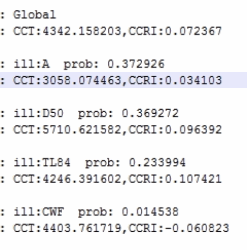
English source figure, PDF p.52, #336.
Transcription of legible screenshot text; source cropping is not reconstructed:
: Global
: CCT:4342.158203,CCRI:0.072367

: ill:A prob: 0.372926
: CCT:3058.074463,CCRI:0.034103

: ill:D50 prob: 0.369272
: CCT:5710.621582,CCRI:0.096392

: ill:TL84 prob: 0.233994
: CCT:4246.391602,CCRI:0.107421

: ill:CWF prob: 0.014538
: CCT:4403.761719,CCRI:-0.060823
This information is used to characterize the color temperature of the scene, only auxiliary information, Global is the comprehensive color temperature, ill lists the probability and color temperature of the first few light sources involved in the WBGain calculation
② temporalDefaultGain for wbGainType3 and weight, respectively, temporalDefaultGain and its weight in wbGainType3
③ wbGainTepType1 is the WBGain calculated by WpType1
④ wbGainType3 is the WBGain calculated by WpType3, and wbWeightType3 is the weight (the weight of WpType1 is 1-wbWeightType3)
⑤ wbgain_s1 and weight are the weight of wbGainTepType1 and wbGainType3, respectively, and wbGainType3
⑥ stategy_result.gain is WBGain under each light source
⑦ prob_total (0.372926), prob_dis (0.151197), prob_LV (0.142857), prob_WPNO (0.383987) respectively mark the total probability, distance probability, brightness probability, and white point number probability of each light source
⑧ spatial gain (rggb) :(1.745900, 1.000000, 1.000000, 1.824126), statistics gain weigth (1.000000) respectively represents the dayGain (policy WBGain) of each light source, each light source based on the probability of WBGain output of statistical white points, then the probability of strategy WBGain is 1 - statistics gain weigth
⑨ type0: gain (rg,bg):(1.287584,2.843158) WPNo(7707) is the white balance gain and number of white points counted in the middle box
⑩ type1: gain (rg,bg):(1.291619,2.862351) WPNo(8557) is the white balance gain and number of white points counted by the large box
2.4.1 Locate the problem from the log
① If the WPNo value is small and there are some white points in the actual scene, you need to readjust the white point condition
② See if the statistics gain weigth of each light source is 1 and whether it is affected by the policy gain
③ Check if the wbWeightType3 weight is 1:
If the scene does have fewer white points, but wbGainType3 may be more consistent with the actual color temperature, you need to adjust the WP_THL and WP_THH divide the current scene into WpType3
In other cases, please refer to the previous two points to explain the adjustment
2.4.2 Grab RAW and simulate
When you need to readjust the white point condition, or if there is no problem from the Log, you need to capture the raw map for white point detection simulation, and view the white point statistics under each light source.
2.4.2.1 (1) Example 1
On the right is the scene in question, and on the left is the effect of the scratch chart readjusting the white point condition
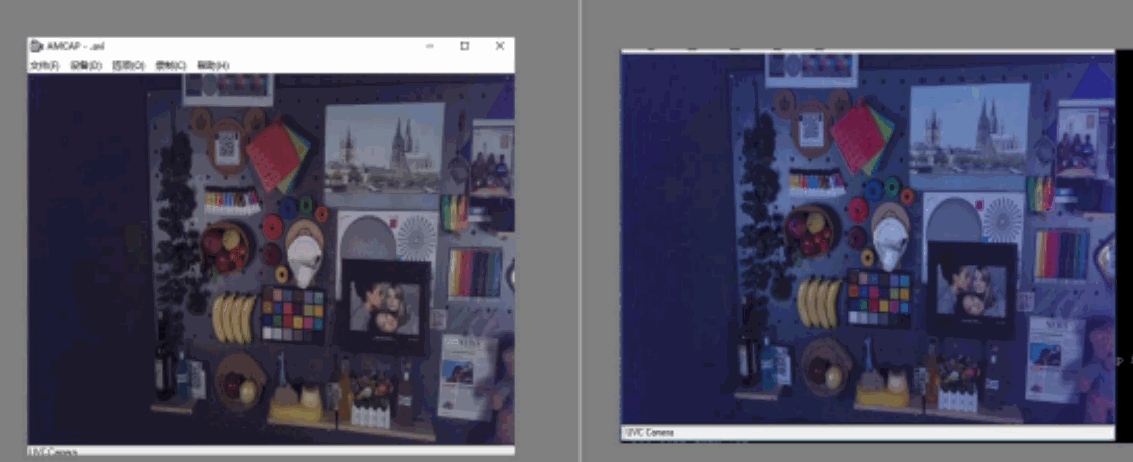
English source figure, PDF p.54, #357.
Procedure:
① Grab Figure 1
② Open RKISPCalibrationTool and import the json file
③ In order to refer to the distribution of white blocks and non-white blocks of the color card under the previous standard light source, you need to re-load Raw Files to import all the figures used in calibration, click FindChart to complete the color card recognition, do not click Calibrate, click Draw WPC From IQ Param to import white point conditions, and display the color patch distribution of the color card.
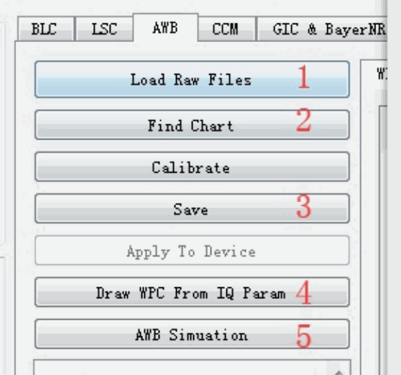
English source figure, PDF p.54, #362.
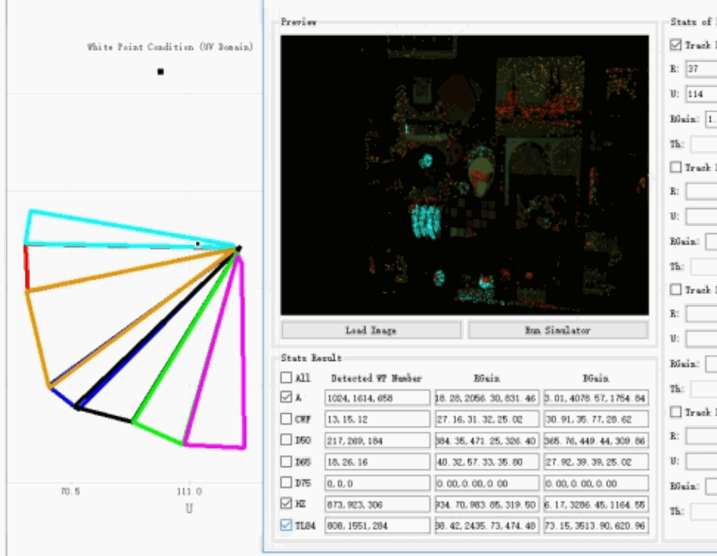
④ Click Load Image on the AWB Simulation interface to import raw Figure 1, and the image and white point detection results will be updated on the interface at the same time, as shown below
English source figure, PDF p.55, #364.
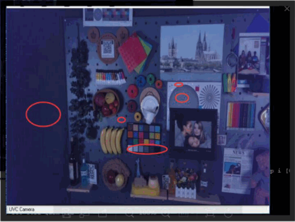
It can be seen that there are very few white spots identified, and the graph is indeed dark. As shown below, similarly circled gray areas should be detected as white spots
English source figure, PDF p.55, #366.
⑤ Click the gray area on the image,
Check whether the mapped points are in the white point interval of XY and UV, if not, you need to adjust the white point condition so that it falls within the interval;
The AWB Simulaton interface will also display the values of R G B and Y of the point, which need to be compared with the limitRange set in JSON to see if it is out of range, if this is the case, you can appropriately relax the limit Range range. Because particularly dark and particularly bright points are affected by noise or the saturation of a channel, their Rgain Bgain will deviate from the actual one, so this range needs to be traded;
If it is within the limitRange range, and it is in the white point range of XY and UV, but it is not recognized as a white point, you need to confirm the TH of YUV, and the th of the point will also be displayed on the AWB Simulaton interface later, refer to this value on the interface to adjust the TH of YUV;
⑥After adjustment, click Save on the AWB interface, and click Run Simlation on the AWB Simulation interface to re-simulate.
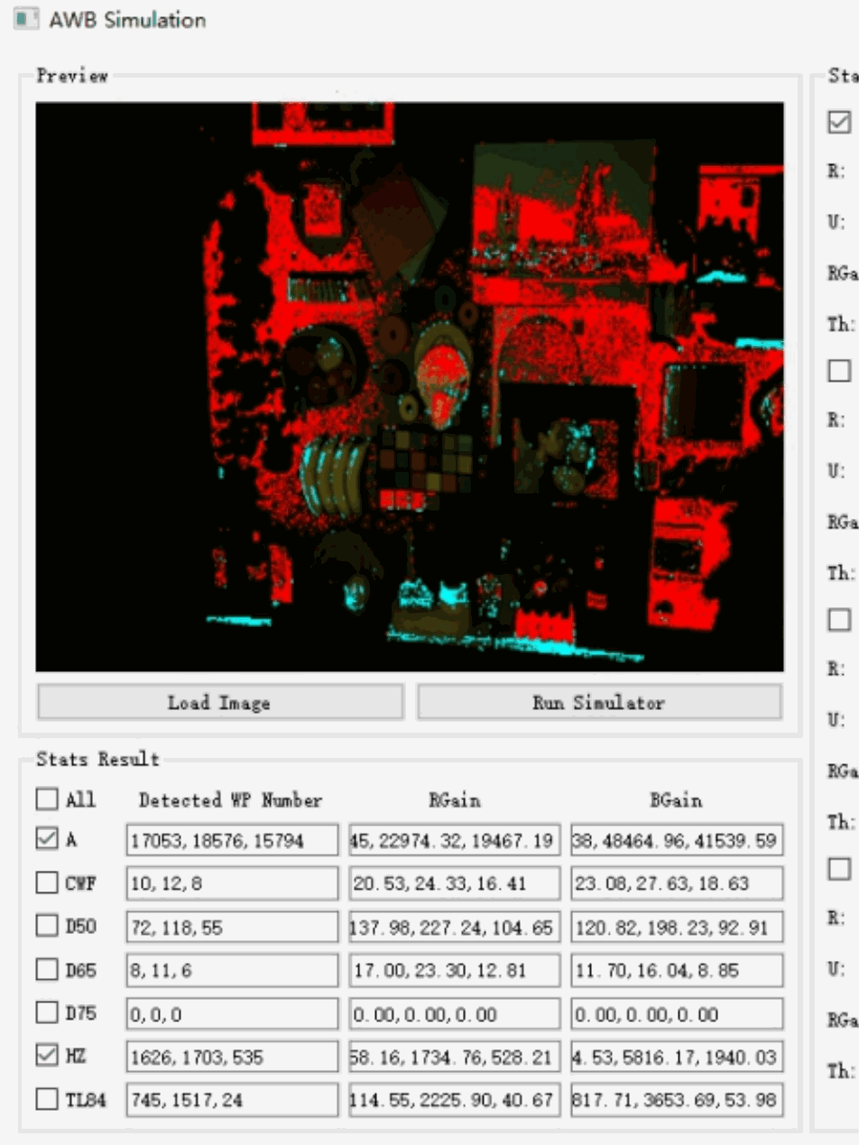
After modifying the white point range of XY and UV, the white point detection is as follows, which solves the problem of abnormal white balance
English source figure, PDF p.56, #373.
2.4.2.2 (2) Example 2 (Simulation tool interface upgrade)
2.4.2.2.1 a. Get RAW online (not supported yet)
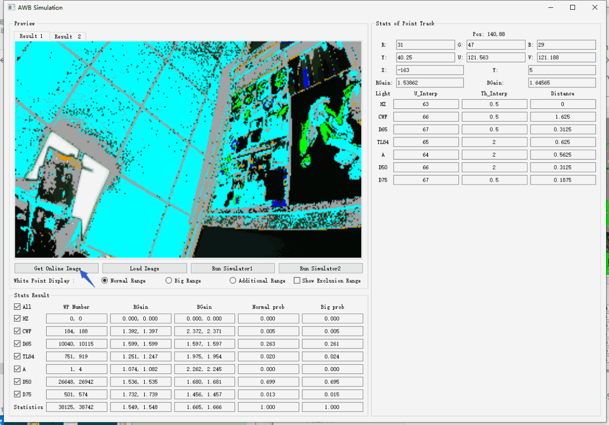
After the tool and board are connected, you can click “Get online Image” to obtain online images and automatically update the simulation results to the interface, simplifying the debugging process compared to Example 1, and refer to ④⑤⑥ of Example 1 for other debugging steps
English source figure, PDF p.57, #377.
Note: The obtained online map will be stored in the root directory of the tool with the suffix .dat2 (e.g. awbinput_rgb_w2880_h1616_ds1_fr1453492.dat2). Load Image on this interface also supports importing files in this format.
2.4.2.2.2 b. Support viewing white points in the middle frame, white points in the large box, points in the additional box, and points in the excluded box
Corresponding to these buttons on the interface, you can view the white point in the middle frame, the white point in the large box, the point in the additional box, and the point in the excluded box! [image-20230201154517001] (Rockchip_color_optimization_guide_isp2x_pngimage-20230201154517001.png)
2.4.2.2.3 c. Calculate the total WBGAIN
! [image-20230201155238824] (Rockchip_color_optimization_guide_isp2x_pngimage-20230201155238824.png)
The final WBGAIN is calculated based on the weighting of the white point of each light source, which is different from the actual algorithm because there are other strategy parts of the actual algorithm. As shown in the figure above, the number of white dots in the middle frame is 38125, and the wbgain is (1.549, 1.665), and the white dots in the large frame is 38742, and the wbgain is (1.548, 1.666).
You can edit the red part to affect the weight, the WP Number is modified, the prob on the right will be automatically updated, and the corresponding data in the Statistics row will also be updated.
2.4.2.2.4 d. Offline simulation of BLC-LSC-WB-CCM-GAMMA effect
This function can be used to assist in viewing the effects of different WBgains to guide AWB debugging, and can be used to view the effects of applying different light sources of LSC to guide LSC debugging, and can be used to check whether there are any abnormalities in the RAW image, and so on.
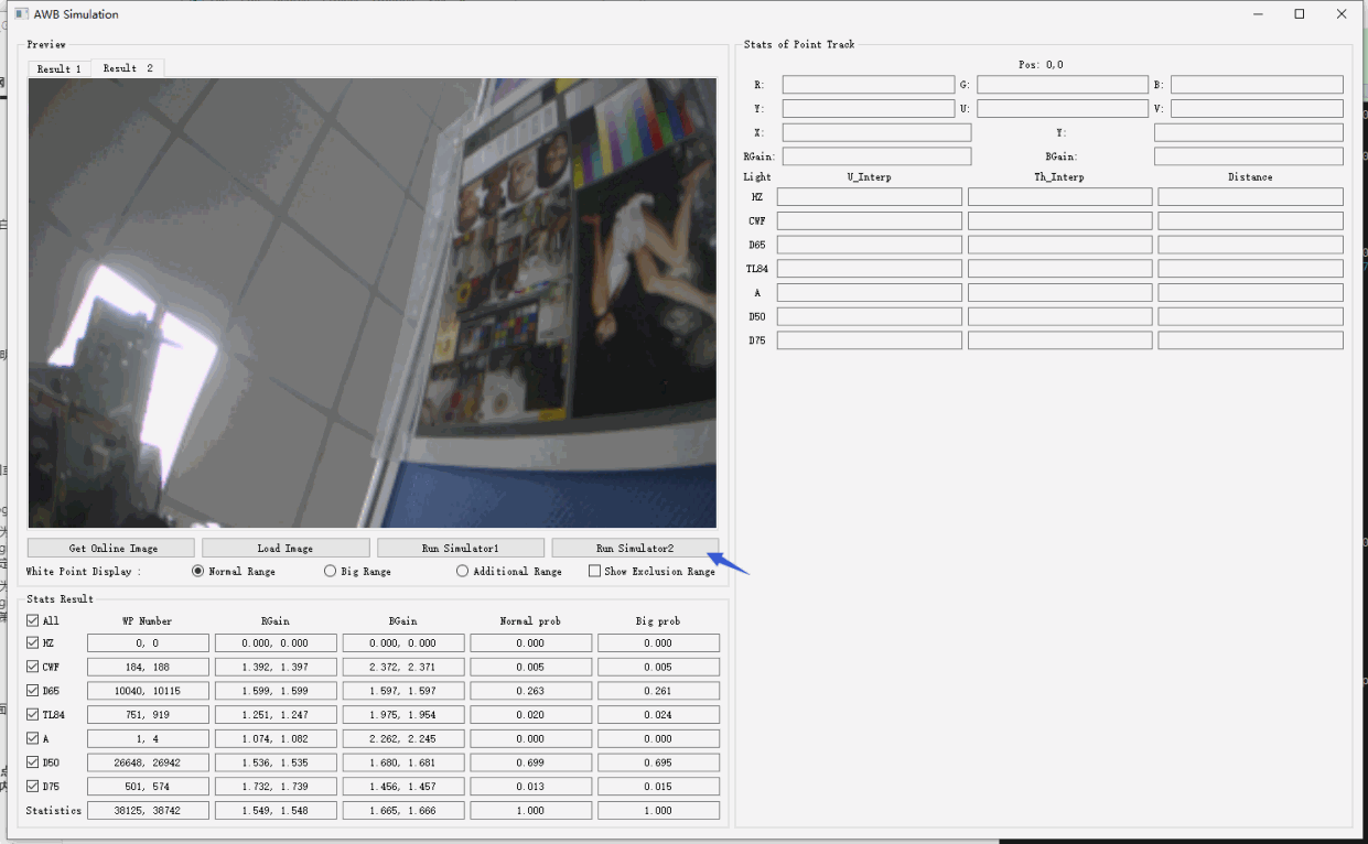
English source figure, PDF p.58, #388.
Click the Run Simulator2 button to get the effect of blc-lsc-wb-ccm-gamma. The BLC LSC CCM Gamma data for the application is from JSON and is printed in the log window of the calibration interface.
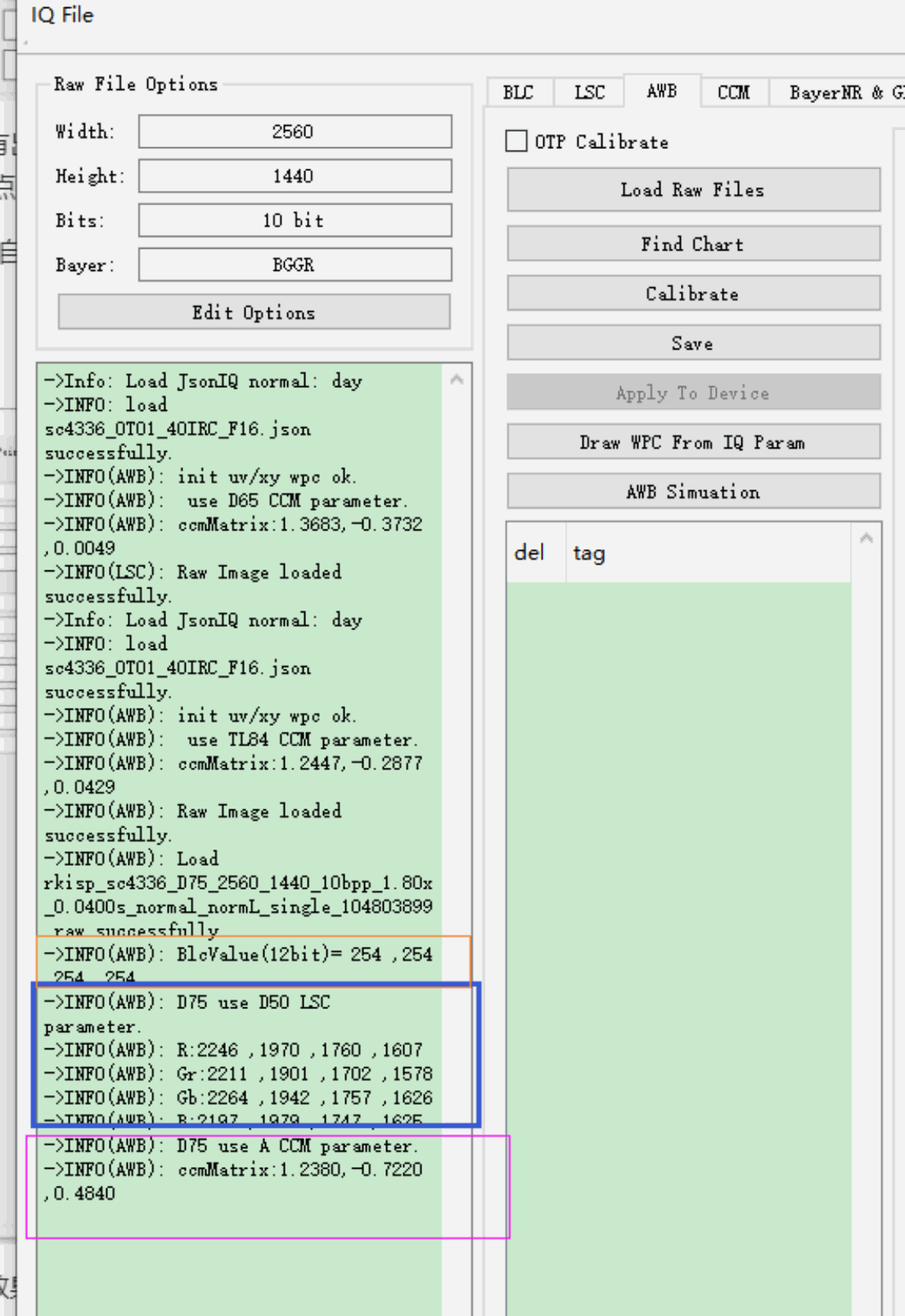
English source figure, PDF p.59, #390.
Transcription of legible screenshot text; source cropping is not reconstructed:
Width: 2560
Height: 1440
Bits: 10 bit
Bayer: BGGR
->Info: Load JsonIQ normal: day
->INFO: load
sc4336_OT01_40IRC_F16.json
successfully.
->INFO(AWB): init uv/xy wpc ok.
->INFO(AWB): use D65 CCM parameter.
->INFO(AWB): ccmMatrix:1.3683,-0.3732
,0.0049
->INFO(LSC): Raw Image loaded
successfully.
->Info: Load JsonIQ normal: day
->INFO: load
sc4336_OT01_40IRC_F16.json
successfully.
->INFO(AWB): init uv/xy wpc ok.
->INFO(AWB): use TL84 CCM parameter.
->INFO(AWB): ccmMatrix:1.2447,-0.2877
,0.0429
->INFO(AWB): Raw Image loaded
successfully.
->INFO(AWB): Load
rkisp_sc4336_D75_2560_1440_10bpp_1.80x
_0.0400s_normal_normL_single_104803899
.raw successfully
->INFO(AWB): BlcValue(12bit)= 254 ,254
,254 ,254
->INFO(AWB): D75 use D50 LSC
parameter.
->INFO(AWB): R:2246 ,1970 ,1760 ,1607
->INFO(AWB): Gr:2211 ,1901 ,1702 ,1578
->INFO(AWB): Gb:2264 ,1942 ,1757 ,1626
->INFO(AWB): B:2197 ,1979 ,1747 ,1625
->INFO(AWB): D75 use A CCM parameter.
->INFO(AWB): ccmMatrix:1.2380,-0.7220
,0.4840
The applied wbgain comes from the wbgain in the middle box, you can directly edit the wbgain, and then click Run Simulator2 to update the simulation results.
2.4.2.3 (3) Example 3 (YUV TH tuning schematic)
In this example, to check whether the white spot missed detection is caused by improper configuration of yuv th, perform the following steps:
a. Determine which is the current light source, determined by the light source interval between the XY domain and the UV domain at the point
b. From the AWB Simulator interface, check whether the distance of the corresponding row of the light source is greater than TH, and if so:
Check which columns of the row of the light source correspond to the U of the YUV condition, and increase the th value of the corresponding column
The specific operation is as follows:
As shown in the figure below, the 22 blocks of the color card are not fully recognized as white points, and the analysis is caused by the distance > th (0.3125>0.1875) under the D65 light source at this time.
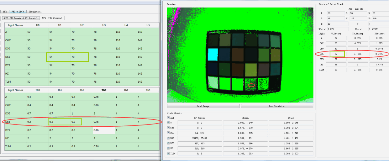
English source figure, PDF p.60, #399.
And because the point is mapped to u 60 under the D65 light source, located between u1(54) and u2(70), the corresponding th1 and th2 thresholds can be adjusted as follows, and the direction of modification can be seen from the white spot detection results.
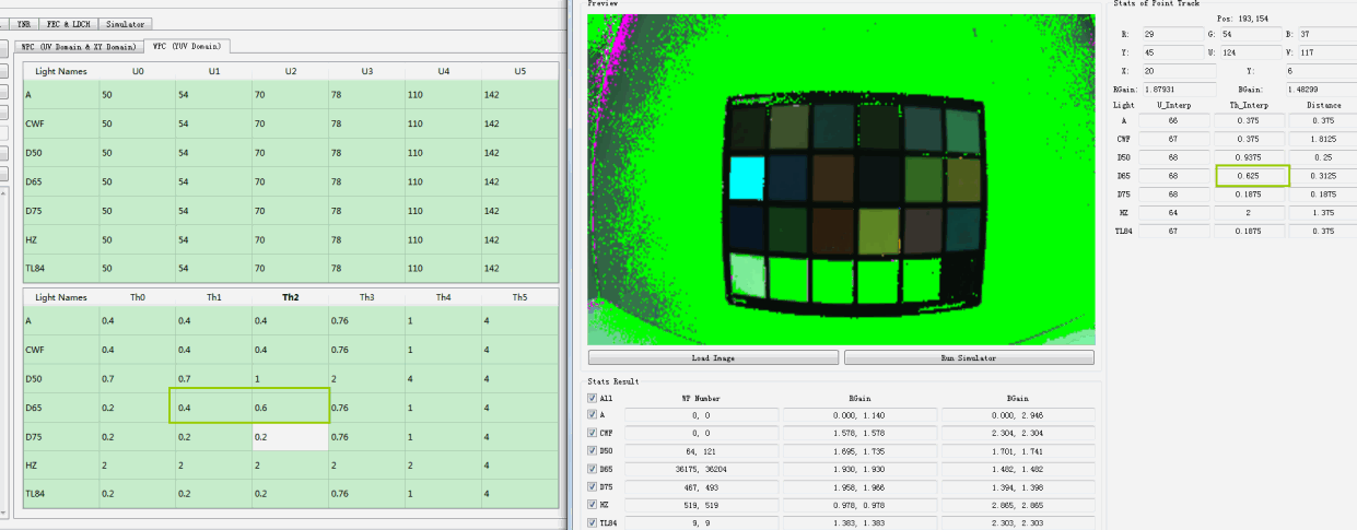
English source figure, PDF p.60, #401.
Concentrate:
When using yuv th to remove non-white points, the operation steps are similar to above, except that the threshold is reduced at this time, but ensure that the white point recognition is not affected.
2.4.3 Examples of special issues
(1) Set the white balance to natural light mode in the webcam application, resulting in automatic white balance not being turned on.
By viewing the log, it is found that the current mode=1 is the manual mode

English source figure, PDF p.60, #407.
Transcription of legible screenshot text; source cropping is not reconstructed:
[09:51:39.57935][AWB]:XCAM DEBUG rk_aiq_awb_algo_v200.cpp:2795: AwbReConfigV200: byPass: 0 mode:1
Changing the white balance mode resolves this issue
(2) During calibration, it was found that the distribution of white spots under HZ A light was not concentrated
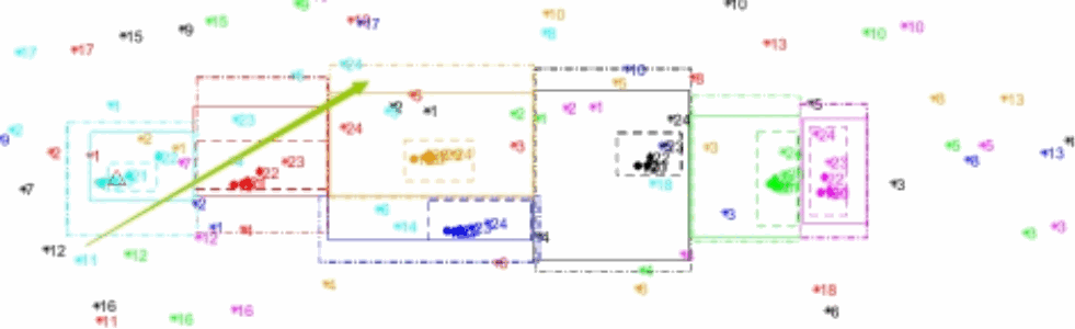
English source figure, PDF p.61, #410.
The actual effect is as follows, the white balance is not done correctly
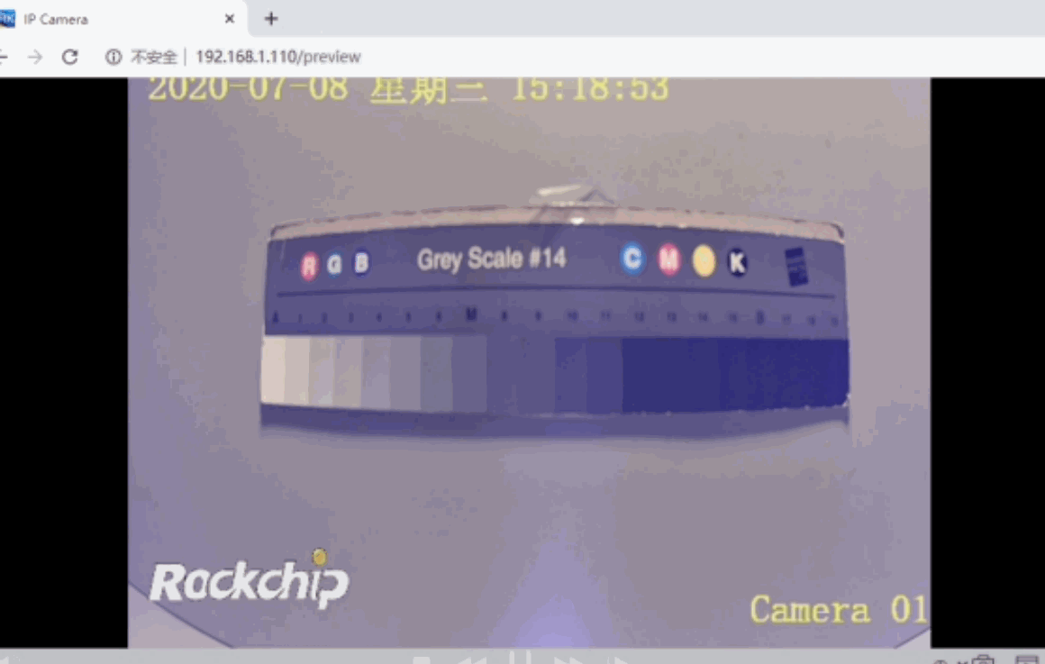
English source figure, PDF p.61, #412.
The later test found that the near-infrared band was not cut off because the infrared filter was unqualified, and it was solved by replacing the infrared filter.
(3) The light source of the CC module is estimated to be oscillating back and forth, causing the color to oscillate
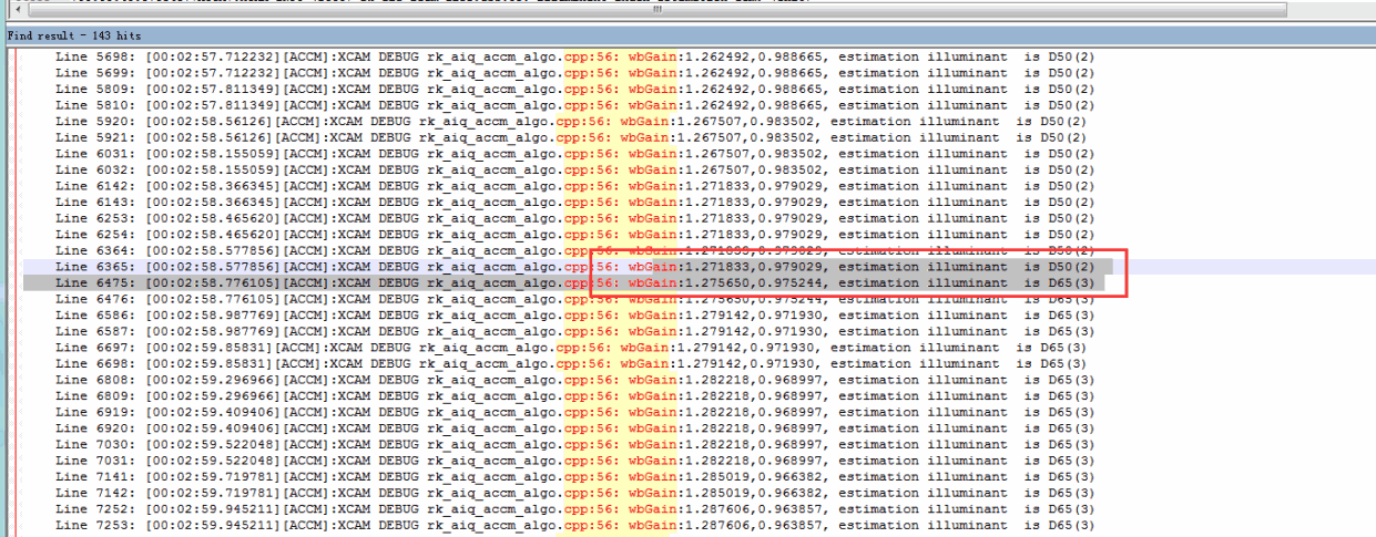
English source figure, PDF p.61, #415.
Transcription of legible screenshot text; source cropping is not reconstructed:
Find result - 143 hits
Line 5698: [00:02:57.712232][ACCM]:XCAM DEBUG rk_aiq_accm_algo.cpp:56: wbGain:1.262492,0.988665, estimation illuminant is D50(2)
Line 5699: [00:02:57.712232][ACCM]:XCAM DEBUG rk_aiq_accm_algo.cpp:56: wbGain:1.262492,0.988665, estimation illuminant is D50(2)
Line 5809: [00:02:57.811349][ACCM]:XCAM DEBUG rk_aiq_accm_algo.cpp:56: wbGain:1.262492,0.988665, estimation illuminant is D50(2)
Line 5810: [00:02:57.811349][ACCM]:XCAM DEBUG rk_aiq_accm_algo.cpp:56: wbGain:1.262492,0.988665, estimation illuminant is D50(2)
Line 5920: [00:02:58.561261][ACCM]:XCAM DEBUG rk_aiq_accm_algo.cpp:56: wbGain:1.267507,0.983502, estimation illuminant is D50(2)
Line 5921: [00:02:58.561261][ACCM]:XCAM DEBUG rk_aiq_accm_algo.cpp:56: wbGain:1.267507,0.983502, estimation illuminant is D50(2)
Line 6031: [00:02:58.155059][ACCM]:XCAM DEBUG rk_aiq_accm_algo.cpp:56: wbGain:1.267507,0.983502, estimation illuminant is D50(2)
Line 6032: [00:02:58.155059][ACCM]:XCAM DEBUG rk_aiq_accm_algo.cpp:56: wbGain:1.267507,0.983502, estimation illuminant is D50(2)
Line 6142: [00:02:58.366345][ACCM]:XCAM DEBUG rk_aiq_accm_algo.cpp:56: wbGain:1.271833,0.979029, estimation illuminant is D50(2)
Line 6143: [00:02:58.366345][ACCM]:XCAM DEBUG rk_aiq_accm_algo.cpp:56: wbGain:1.271833,0.979029, estimation illuminant is D50(2)
Line 6253: [00:02:58.465620][ACCM]:XCAM DEBUG rk_aiq_accm_algo.cpp:56: wbGain:1.271833,0.979029, estimation illuminant is D50(2)
Line 6254: [00:02:58.465620][ACCM]:XCAM DEBUG rk_aiq_accm_algo.cpp:56: wbGain:1.271833,0.979029, estimation illuminant is D50(2)
Line 6364: [00:02:58.577856][ACCM]:XCAM DEBUG rk_aiq_accm_algo.cpp:56: wbGain:1.271833,0.979029, estimation illuminant is D50(2)
Line 6365: [00:02:58.577856][ACCM]:XCAM DEBUG rk_aiq_accm_algo.cpp:56: wbGain:1.271833,0.979029, estimation illuminant is D50(2)
Line 6475: [00:02:58.776105][ACCM]:XCAM DEBUG rk_aiq_accm_algo.cpp:56: wbGain:1.275650,0.975244, estimation illuminant is D65(3)
Line 6476: [00:02:58.776105][ACCM]:XCAM DEBUG rk_aiq_accm_algo.cpp:56: wbGain:1.275650,0.975244, estimation illuminant is D65(3)
Line 6586: [00:02:58.987769][ACCM]:XCAM DEBUG rk_aiq_accm_algo.cpp:56: wbGain:1.279142,0.971930, estimation illuminant is D65(3)
Line 6587: [00:02:58.987769][ACCM]:XCAM DEBUG rk_aiq_accm_algo.cpp:56: wbGain:1.279142,0.971930, estimation illuminant is D65(3)
Line 6697: [00:02:59.85831][ACCM]:XCAM DEBUG rk_aiq_accm_algo.cpp:56: wbGain:1.279142,0.971930, estimation illuminant is D65(3)
Line 6698: [00:02:59.85831][ACCM]:XCAM DEBUG rk_aiq_accm_algo.cpp:56: wbGain:1.279142,0.971930, estimation illuminant is D65(3)
Line 6808: [00:02:59.296966][ACCM]:XCAM DEBUG rk_aiq_accm_algo.cpp:56: wbGain:1.282218,0.968997, estimation illuminant is D65(3)
Line 6809: [00:02:59.296966][ACCM]:XCAM DEBUG rk_aiq_accm_algo.cpp:56: wbGain:1.282218,0.968997, estimation illuminant is D65(3)
Line 6919: [00:02:59.409406][ACCM]:XCAM DEBUG rk_aiq_accm_algo.cpp:56: wbGain:1.282218,0.968997, estimation illuminant is D65(3)
Line 6920: [00:02:59.409406][ACCM]:XCAM DEBUG rk_aiq_accm_algo.cpp:56: wbGain:1.282218,0.968997, estimation illuminant is D65(3)
Line 7030: [00:02:59.522048][ACCM]:XCAM DEBUG rk_aiq_accm_algo.cpp:56: wbGain:1.282218,0.968997, estimation illuminant is D65(3)
Line 7031: [00:02:59.522048][ACCM]:XCAM DEBUG rk_aiq_accm_algo.cpp:56: wbGain:1.282218,0.968997, estimation illuminant is D65(3)
Line 7141: [00:02:59.719781][ACCM]:XCAM DEBUG rk_aiq_accm_algo.cpp:56: wbGain:1.285019,0.966382, estimation illuminant is D65(3)
Line 7142: [00:02:59.719781][ACCM]:XCAM DEBUG rk_aiq_accm_algo.cpp:56: wbGain:1.285019,0.966382, estimation illuminant is D65(3)
Line 7252: [00:02:59.945211][ACCM]:XCAM DEBUG rk_aiq_accm_algo.cpp:56: wbGain:1.287606,0.963857, estimation illuminant is D65(3)
Line 7253: [00:02:59.945211][ACCM]:XCAM DEBUG rk_aiq_accm_algo.cpp:56: wbGain:1.287606,0.963857, estimation illuminant is D65(3)
By increasing the value value in the tolerance node in JSON, when the wbgain change is less than this value, it will not be updated, so as to achieve the purpose of stability. In this example, change the parameter in XML to
<tolerance index="1" type="struct" size="[1 1]">
    <LV index="1" type="double" size="[1 4]">
        [0 64 128 256.0000 ]
    </LV>
    <value index="1" type="double" size="[1 4]">
        [0.05 0.05 0.05 0.05 ]
    </value>
</tolerance>
3 Base color adjustment CCM
3.1 Description of the feature
Since the Sensor spectral distribution function is difficult to match exactly with the visual response function, the crossover effect and response intensity of the spectral response can be corrected by a color correction matrix (CCM), so that the image captured by the front end is consistent with the color of human vision.
The CCM calibration tool supports 3x3 CCM (aij) pre-calibration of 24-color cards.
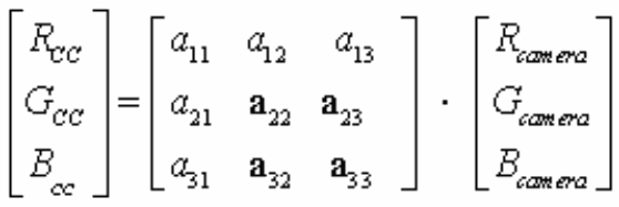
English source figure, PDF p.62, #422.
[R_CC, G_CC, B_CC]^T = [[a11,a12,a13],[a21,a22,a23],[a31,a32,a33]] * [R_camera,G_camera,B_camera]^T
It supports multiple groups of CCMs with different color temperatures, and when the ISP is running, the global saturation or local saturation can be adjusted according to the gain node configured by IQ parameters to realize the dynamic adjustment of the CCM matrix coefficient.

English source figure, PDF p.62, #424.
[R_CC,G_CC,B_CC]^T = alpha * scale * [[a11-1,a12,a13],[a21,a22-1,a23],[a31,a32,a33-1]] * [R_camera,G_camera,B_camera]^T + [R_camera,G_camera,B_camera]^T
3.2 Key parameters
The parameters of the ISP are listed in the ccm_calib node of the IQ json file, and the json parameters only take effect in automatic mode.
3.2.1 Enable control and mode selection
Under the control node
| Parameter | Description |
|---|---|
| enable | Color correction enable switch, 1 means enabled; The value is 0 or 1 |
| wbgain_tolerance | Color correction white balance gain change tolerance: When the difference in white balance gain statistical value is less than this threshold, it can be considered that the white balance gain meets the stability conditions of color correction; The value range is 0.0-1, and the recommended value is 0.3 |
| gain_tolerance | Color correction exposure gain change tolerance: When the difference in exposure gain statistical value is less than this threshold, it can be considered that the exposure gain meets the stability conditions of color correction; The value range is 0.0-1, and the recommended value is 0.5 |
3.2.2 Brightness-saturation adjustment
Under the lumaCCM node
3.2.2.1 Pixel brightness related saturation adjustment
For pixels in the specified Y interval, the color correction intensity can be adjusted.
| Parameter | Description |
|---|---|
| RGB2Y_para | Calculated coefficients from RGB to Y, 7-bit fixed-point values; Integer, value range [0,128], adjustment |
| low_bound_pos_bit | Pixel brightness (Y) - brightness threshold of color correction (CC) intensity, integer in the range of [0,10] |
| y_alpha_curve | Intensity of pixel brightness (Y) - color correction (CC) intensity (alpha), 1024 means 1 times the intensity, 0 means no correction, integer, value range [0, 1024] |
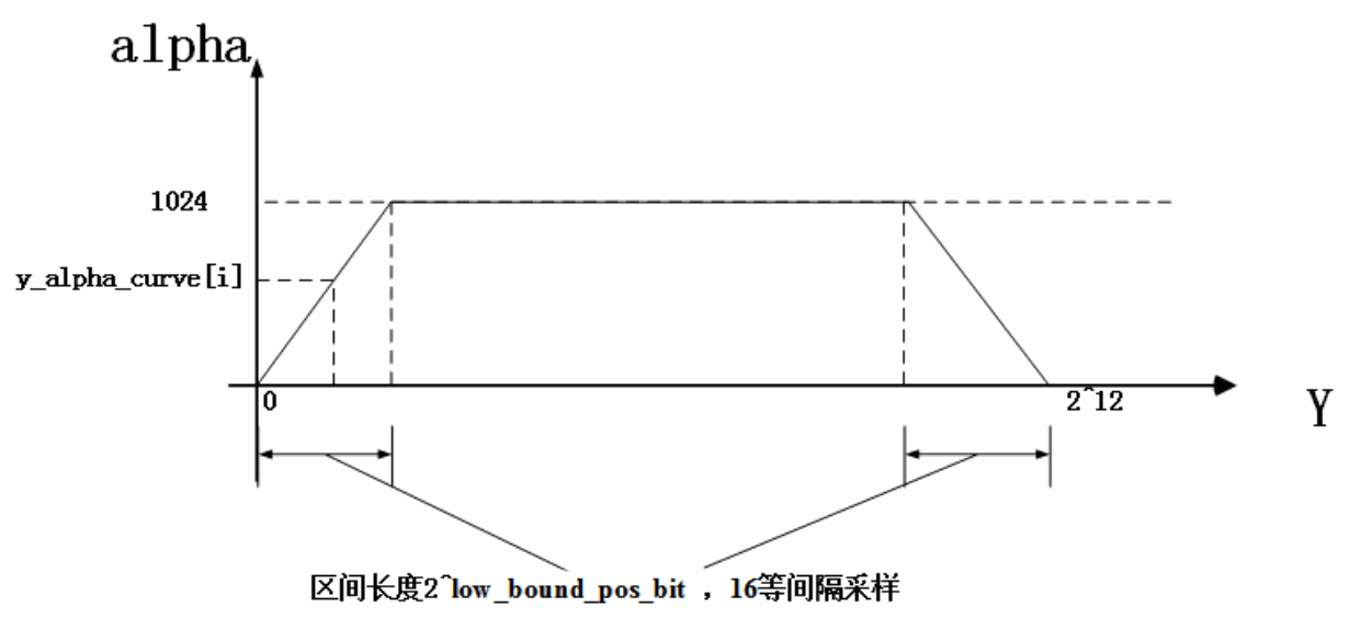
English source figure, PDF p.63, #435.
Figure Y-CcAlpha
3.2.2.2 Global saturation adjustment
Under the gain_alphaScale_curve node
Different exposure gains correspond to different correction intensity scales, corresponding to the parameters under the node gain_alphaScale_curve
| Parameter | Description |
|---|---|
| gain | The exposure gain component of gain-scale, decimal, value greater than 0 |
| scale | The corrected intensity component of gain-scale, decimal, value range [0,1] |
3.2.3 Automatic CCM parameters
Under the TuningPara node
| Parameter | Description |
|---|---|
| damp_enable | Color correction matrix smoothing function switch, 1 means to use this function; The value is 0 or 1 |
3.2.3.1 CCM matrix calculation method selection
The CCM module has the following two CCM matrix calculation methods: (1) Select the standard white balance gain and white balance gain statistics CCM parameters of the light source with the smallest Euclidean distance; (2) The CCM matrix is weighted to calculate the CCM matrix by using the distance probability between the standard white balance gain and the white balance gain statistical value of each light source as the weight. The distance probability prob for each light source is calculated as follows:

dist = sqrt((Rgain-awbGain[0])^2 * wr + (Bgain-awbGain[1])^2 * wb)
prob = exp(-dist^2 / sigma^2)
where \(Rgain, Bgain\) is the statistical value of white balance gain, \(awbGain\) is the standard white balance gain of each light source, \(wr, wb\) is \(R, B\) channel weight, \(sigma\) is the standard deviation of \(dist\) of all light sources.
Under the illu_estim node
| Parameter | Description |
|---|---|
| interp_enable | CCM weighted calculation enable, 1 means enable; The value is 0 or 1 |
3.2.3.2 CCM matrix weighting calculation
Under the illu_estim node
| Parameter | Description |
|---|---|
| default_illu | Default light source name, when the distance probability of each light source is equal, the CCM parameter of the default light source |
| weightRB | The channel weight of R(G)gain will use |
| prob_limit | The lower limit value of the distance probability that light sources with a distance probability less than this value will not participate in the CCM matrix calculation |
| frame_no | The number of smoothed frames, taken from the distance probability average of frame_no frames for CCM matrix weighting calculation |
3.2.3.3 CCM selects control parameters
According to the white balance gain, the parameters of the corresponding light source are automatically selected, and different exposure gains (gain) corresponding to different saturation (sat) CCM can be configured under a light source
Under the aCcmCof node
| Parameter | Description |
|---|---|
| name | Light source name |
| awbGain | The standard white balance gain corresponding to the light source is generated by the calibration tool and the value is greater than 0 |
| minDist | The white balance gain distance threshold corresponding to the light source, generated by the calibration tool, will be used to calculate the light source distance probability, and when the dist is less than this value, set the prob of the light source to 1 |
| matrixUsed | The CCM |
| gains | The exposure gain component of gains-sat, decimal, value greater than 0 |
| sat | The saturation component of gains-sat, decimal, with a value greater than 0 |
3.2.3.4 CCM parameters
| Parameter | Description |
|---|---|
| Name | CCM Name |
| illumination | Light source name |
| saturation | The corresponding saturation is generated by the calibration tool, and the value is greater than or equal to 0 |
| ccMatrix | Color correction matrix, generated by calibration tool, decimal, value range [-8, 7.992] |
| ccOffsets | RGB component offset, generated by the calibration tool, value range [-4096, 4095] |
3.3 CCM calibration
Complete the CCM calibration work in accordance with the “Rockchip_IQ_Tools_Guide_ISP2x_CN”.
3.3.1 RAW data acquisition
3.3.1.1 Calibration light source selection
Seven different color temperature light sources: D50, D65, D75, A, CWF, HZ, TL84
3.3.1.2 Acquisition steps
Step 1. The color card is placed in the center of the background wall of the light box to ensure uniform light sources on the left and right sides; If the project has high color requirements, you can also put the corresponding color next to it, such as a skin tone card, to confirm the effect.
Step 2. Adjust the exposure so that each color block of the color card after applying gamma cannot be overexposed, and automatic exposure is recommended
Step 3. When shooting, adjust the object distance so that the proportion of color cards in the frame is 1/9.
3.3.2 calibration
3.3.2.1 steps
Step 1. For RAW data import and selection of 24-color areas, please refer to Section 4.5 “CCM Calibration” of Rockchip_IQ_Tools_Guide_ISP2x_CN.
Step 2. Configure calibration parameters
(1) Set gamma: Select the gamma curve that the camera will use. Support Normal, HDR, Night mode, and also support customization.
(2) Set patch weight: Configure the patch weight in the 6x4 table, and the patch position corresponds to the position in the table.
(3) Click the “Calibrate” button for calibration and obtain CCM. You can manually adjust the Saturation on the Calibration page until the corrected effect or chromatic difference map in the Result meets the requirements.
3.3.2.2 Introduction to chromatic aberration charts
According to the deviation direction and interval of the standard color patch in the chromatic difference chart, which component is abnormal is analyzed, as follows:
(1) If the color block of the camera is farther away from the origin than the color block of the idea, the saturation of the camera is higher than that of the idea
(2) The distance from the color block of the camera to the origin is smaller than that of the color block of the idea, and the saturation of the camera is lower than that of the idea
Case picture:
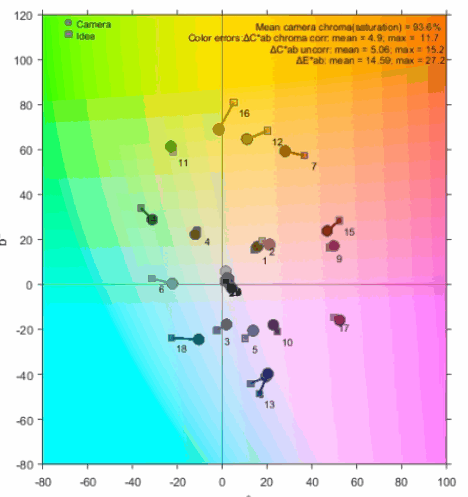
English source figure, PDF p.67, #479.
Color patch 15 (red block) and color block 14 (green) camera saturation is lower than IDEA, but it belongs to the category of relatively small deviation
Color block 13 (blue) is purple in the direction of purple, and the human eye may also perceive color block 13 to be purple, so this deviation is acceptable.
Generally, it is necessary to ensure that the deviation of the 13-15 color block is not too large, which almost represents the three primary colors, and other colors can be superimposed from these three colors.
If the color cast of 13-15 color blocks, or other color blocks of more concern, you can increase the weight of the color blocks, but pay attention to the influence on the color cast of other color blocks.
3.3.2.3 Considerations
(1) When identifying the 24-color area, make sure that the black border of each color block is not selected
(2) After adjusting the gamma curve, it may be necessary to recalibrate the CCM, so it is best to adjust the gamma first
(3) Inappropriate brightness of the calibration map will affect the saturation characteristics of the calibrated CCM, the CCM saturation determined by the too bright RAW icon is low, and the CCM saturation determined by the too dark RAW icon is high
(4) It is recommended that objective indicators are as follows, but they can vary from project to project and do not focus on these objective indicators
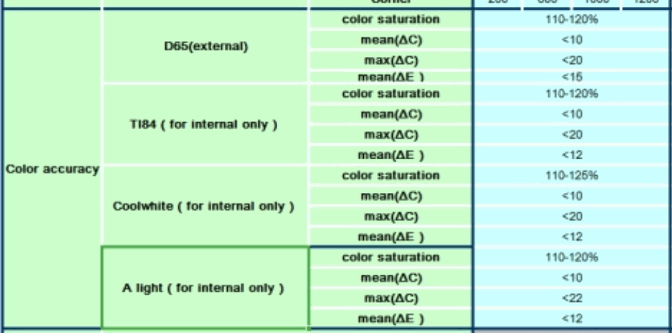
English source figure, PDF p.68, #489.
| Source / use | Metric | Source recommendation |
|---|---|---|
| D65 (external) | Color saturation | 110-120% |
| D65 (external) | mean(ΔC) | <10 |
| D65 (external) | max(ΔC) | <20 |
| D65 (external) | mean(ΔE) | <15 |
| TL84 (internal only) | Color saturation | 110-120% |
| TL84 (internal only) | mean(ΔC) | <10 |
| TL84 (internal only) | max(ΔC) | <20 |
| TL84 (internal only) | mean(ΔE) | <12 |
| Coolwhite (internal only) | Color saturation | 110-125% |
| Coolwhite (internal only) | mean(ΔC) | <10 |
| Coolwhite (internal only) | max(ΔC) | <20 |
| Coolwhite (internal only) | mean(ΔE) | <12 |
| A (internal only) | Color saturation | 110-120% |
| A (internal only) | mean(ΔC) | <10 |
| A (internal only) | max(ΔC) | <22 |
| A (internal only) | mean(ΔE) | <12 |
3.4 Color adjustment
3.4.1 Overall color saturation adjustment
3.4.1.1 Adjust the parameters of the gain_alphaScale_curve
The scale value can be adjusted appropriately in the range of [0, 1.0], affecting the final color correction intensity, the smaller the scale, the lower the color saturation, and vice versa, the color saturation increases.
3.4.1.2 Adjust gains-sat
The smaller the SAT, the lower the color saturation, and conversely, the color saturation increases. Different light sources can adjust different parameters.
3.4.1.3 Increase highly saturated CCM
When the first two points are adjusted to the maximum value, the saturation is still not enough, and the CCM with higher saturation needs to be recalibrated, and the maximum sat value in gains-sat must be adjusted to the increased saturation.
3.4.1.4 Reduce the color saturation of dark pixels
Reduce the value in the y_alpha_curve to reduce the color saturation of dark pixels, noting that the last value needs to be 1024, otherwise it will affect the color saturation of other brightness in the image.
3.4.2 Some color adjustments
When the overall color saturation adjustment is completed before, the color still does not achieve the expected effect, you can try it as follows:
(1) When it is necessary to adjust the color consistent with the human eye vision, confirm whether the white balance is correct;
(2) When it is necessary to adjust the color consistent with the contrast machine, confirm whether the white balance is consistent;
(3) When it is necessary to adjust the color consistent with the comparison machine, confirm whether the brightness is close
(4) If the white balance is confirmed to be consistent or correct and the brightness is close, the color still does not meet the expectations, and then adjust the CCM related parameters to achieve the goal.
3.4.2.1 Confirm that the white balance is correct
Important: Whether the white object is color-cast.
Method:
Eyes, whether the white object in the video is white;
Grab the picture to see if the R/G/B components of the white block are quite different.
3.4.2.2 Confirm that the white balance is consistent with the comparator and adjusted
(1) If the white balance of the comparator is correct, and the color cast of the white object of RK is obvious, first make the white balance more correct through the white balance module;
(2) If the color cast of the white object of the comparator is more obvious, and the white balance of RK is relatively correct, it is necessary to distinguish whether it is caused by the defect of the white balance algorithm of the comparator or caused by the different tone preferences of the comparator; If the tone preference is different, you can first adjust the hue through the white balance module to make the two consistent, or use tools such as faststone to adjust the contrast machine tone is the same as that of RK; If it is caused by a defect in the white balance algorithm of the comparer, you can increase the number of white points in the scene, recapture the image, or use tools such as faststone to adjust the tone of the comparator to be the same as that of RK.
(3) How to distinguish whether the color cast of the white object of the comparison machine is more obvious because of the defect of the white balance algorithm of the comparison machine, or whether it is caused by the different color preferences of the comparison machine
a. If the scene only has white objects and the brightness is suitable, the white or partial color of the contrast machine is most likely because the contrast machine has made a tone adjustment;
b. Otherwise, it is caused by the defect of the comparison machine algorithm;
3.4.2.3 Adjust the brightness to match the comparator
(1) By adjusting the brightness related modules (AE, Gamma, Dehaze, HDR) to make the brightness close, a certain gap is allowed
(2) Or adjust the brightness of the contrast machine with tools such as faststone to be the same as that of RK
3.4.3 Adjust CCM
3.4.3.1 Recalibrate the CCM with the tool
Find the color patch closest to the color in the 24-color card, increase the weight of the color block, and recalibrate the CCM.
Case:
In the chromatic difference plot on the left below, the color shift of the 6/18th block is relatively large, for this, you can set the neutral block (blocks 19-24) weight to 0, set the 6th block to 16, and set the 18th block weight to 8. In addition, in order to reduce the impact of the above adjustment on other color blocks, the weight of the three primary color blocks (13th-15 color blocks) is set to 8, and the weight of the skin color block (2nd color block) is also set to 8, so that the resulting color difference figure is shown on the right below, and the color cast of the 6/18 color block is reduced.
English source figure, PDF p.70, #526.
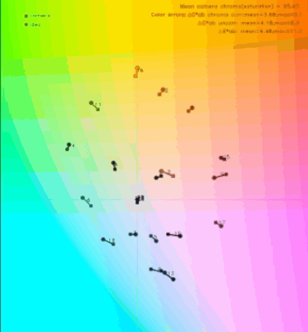
English source figure, PDF p.70, #527.
3.4.3.2 Manually adjust the CCM
3.4.3.2.1 Get the RK RGB value
Use the RK machine to grab the image and obtain the RK RGB value
3.4.3.2.2 Get the target RGB value
(1) When there is a contrast machine
Use a contrast machine to grab the image and obtain the target value, but you need to keep it close to the luminance white balance of RK
(2) When there is no contrast machine
Use tools such as faststone to adjust a color of interest on the RK acquisition map until the color is expected to match.
English source figure, PDF p.71, #536.

English source figure, PDF p.71, #537.
For example: adjust the B component as the target value, use fastone to subtract the B channel by 17, the green shown in the lower right is the expected color,
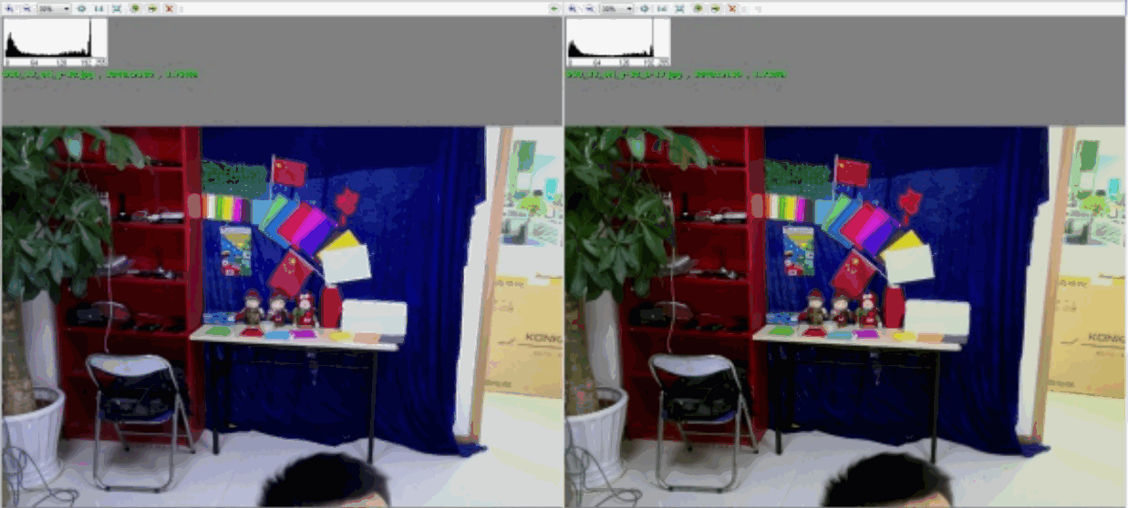
English source figure, PDF p.71, #539.
Compare the green RGB of RK at this time to 64 85 90, the target is 65 86 69, and then you know that to adjust the CCM to reduce the B component, then the two greens will be close
(3)The target value of 24-color card human eye vision is:
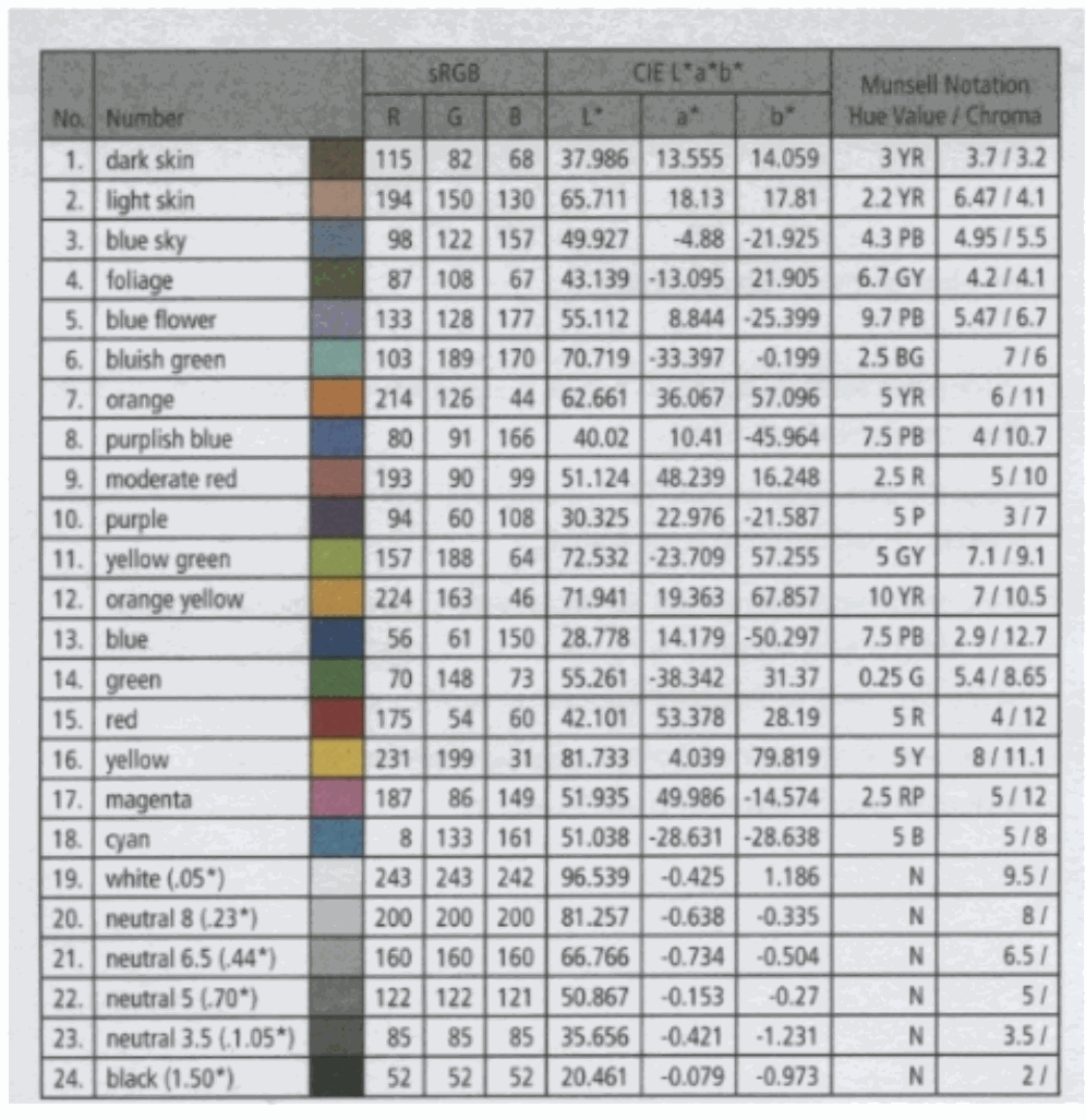
English source figure, PDF p.72, #542.
| No. | Patch | sRGB R | G | B | CIE L* | a* | b* | Munsell Hue | Value / Chroma |
|---|---|---|---|---|---|---|---|---|---|
| 1 | dark skin | 115 | 82 | 68 | 37.986 | 13.555 | 14.059 | 3 YR | 3.7 / 3.2 |
| 2 | light skin | 194 | 150 | 130 | 65.711 | 18.13 | 17.81 | 2.2 YR | 6.47 / 4.1 |
| 3 | blue sky | 98 | 122 | 157 | 49.927 | -4.88 | -21.925 | 4.3 PB | 4.95 / 5.5 |
| 4 | foliage | 87 | 108 | 67 | 43.139 | -13.095 | 21.905 | 6.7 GY | 4.2 / 4.1 |
| 5 | blue flower | 133 | 128 | 177 | 55.112 | 8.844 | -25.399 | 9.7 PB | 5.47 / 6.7 |
| 6 | bluish green | 103 | 189 | 170 | 70.719 | -33.397 | -0.199 | 2.5 BG | 7 / 6 |
| 7 | orange | 214 | 126 | 44 | 62.661 | 36.067 | 57.096 | 5 YR | 6 / 11 |
| 8 | purplish blue | 80 | 91 | 166 | 40.02 | 10.41 | -45.964 | 7.5 PB | 4 / 10.7 |
| 9 | moderate red | 193 | 90 | 99 | 51.124 | 48.239 | 16.248 | 2.5 R | 5 / 10 |
| 10 | purple | 94 | 60 | 108 | 30.325 | 22.976 | -21.587 | 5 P | 3 / 7 |
| 11 | yellow green | 157 | 188 | 64 | 72.532 | -23.709 | 57.255 | 5 GY | 7.1 / 9.1 |
| 12 | orange yellow | 224 | 163 | 46 | 71.941 | 19.363 | 67.857 | 10 YR | 7 / 10.5 |
| 13 | blue | 56 | 61 | 150 | 28.778 | 14.179 | -50.297 | 7.5 PB | 2.9 / 12.7 |
| 14 | green | 70 | 148 | 73 | 55.261 | -38.342 | 31.37 | 0.25 G | 5.4 / 8.65 |
| 15 | red | 175 | 54 | 60 | 42.101 | 53.378 | 28.19 | 5 R | 4 / 12 |
| 16 | yellow | 231 | 199 | 31 | 81.733 | 4.039 | 79.819 | 5 Y | 8 / 11.1 |
| 17 | magenta | 187 | 86 | 149 | 51.935 | 49.986 | -14.574 | 2.5 RP | 5 / 12 |
| 18 | cyan | 8 | 133 | 161 | 51.038 | -28.631 | -28.638 | 5 B | 5 / 8 |
| 19 | white (.05*) | 243 | 243 | 242 | 96.539 | -0.425 | 1.186 | N | 9.5 / |
| 20 | neutral 8 (.23*) | 200 | 200 | 200 | 81.257 | -0.638 | -0.335 | N | 8 / |
| 21 | neutral 6.5 (.44*) | 160 | 160 | 160 | 66.766 | -0.734 | -0.504 | N | 6.5 / |
| 22 | neutral 5 (.70*) | 122 | 122 | 121 | 50.867 | -0.153 | -0.27 | N | 5 / |
| 23 | neutral 3.5 (1.05*) | 85 | 85 | 85 | 35.656 | -0.421 | -1.231 | N | 3.5 / |
| 24 | black (1.50*) | 52 | 52 | 52 | 20.461 | -0.079 | -0.973 | N | 2 / |
3.4.3.2.3 Adjust the CCM description
Compare the current RGB and target RGB values, and manually adjust the CCM to make the RGB of the two close to each other.
(1) CCM regulation constraints
The formula for the color correction matrix is as follows:
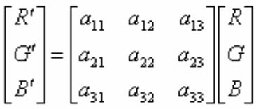
English source figure, PDF p.72, #547.
[R',G',B']^T = [[a11,a12,a13],[a21,a22,a23],[a31,a32,a33]] * [R,G,B]^T
In order to ensure that the white balance is not destroyed, the parameters must meet the conditions:
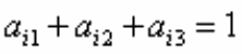
English source figure, PDF p.72, #549.
a_i1 + a_i2 + a_i3 = 1
Each channel is primarily derived from the color component of the original channel, so the conditions must be met:

English source figure, PDF p.72, #551.
a_ii >= 1
At the same time, try to make the main diagonal element value difference small, and try to make the elements other than the main diagonal negative.

English source figure, PDF p.72, #553.
a13

English source figure, PDF p.72, #554.
a31
If a13 is positive, highly saturated red becomes purplish; if a31 is positive, highly saturated blue becomes purplish.

English source figure, PDF p.73, #556.
a21
When a21 is negative, the larger its absolute value, the smaller the corrected red G component, and the higher the red saturation. When a23 is negative, the larger its absolute value, the smaller the corrected blue G component and the higher the blue saturation.

English source figure, PDF p.73, #558.
a23
(2)Summary of common color casts:

English source figure, PDF p.73, #561.
a13

English source figure, PDF p.73, #562.
a31

English source figure, PDF p.73, #563.
a13

English source figure, PDF p.73, #564.
a31
When blue (red) is purplish and a13 (a31) is positive, reduce the R (B) component by changing a13 (a31) from a small positive value near zero to a smaller negative value.

English source figure, PDF p.73, #566.
a23

English source figure, PDF p.73, #567.
a21
When blue (red) is oversaturated and a23 (a21) is negative, increase G by reducing the absolute value of a23 (a21).

English source figure, PDF p.73, #569.
a23

English source figure, PDF p.73, #570.
a21

English source figure, PDF p.73, #572.
a13

English source figure, PDF p.73, #573.
a11

English source figure, PDF p.73, #574.
a12
When purple is bluish, increase R by increasing a13 and decreasing a11 and a12; or reduce B by decreasing a33 and increasing a31 and a32.

English source figure, PDF p.73, #576.
a33

English source figure, PDF p.73, #577.
a31

English source figure, PDF p.73, #578.
a32

English source figure, PDF p.73, #580.
a21

English source figure, PDF p.73, #581.
a22
When red is orange, reduce G by decreasing a21 and increasing a22.
When skin is yellowish green, reduce G and increase B: greatly decrease a22 and increase a23, fine-tune a21; greatly increase a31 and decrease a32, fine-tune a33.

English source figure, PDF p.73, #584.
a22

English source figure, PDF p.73, #585.
a23

English source figure, PDF p.73, #586.
a21

English source figure, PDF p.73, #587.
a31

English source figure, PDF p.73, #588.
a32

English source figure, PDF p.73, #589.
a33
3.4.3.2.4 Adjust CCM example
(1) Case 1 Red orange:
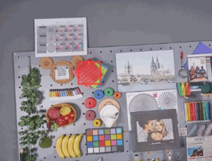
English source figure, PDF p.73, #593.
Using faststone to adjust RGB, it was found that reducing the G component could improve the problem of orange casting, and the target RGB value for the red plastic sheet was [212 63 79].
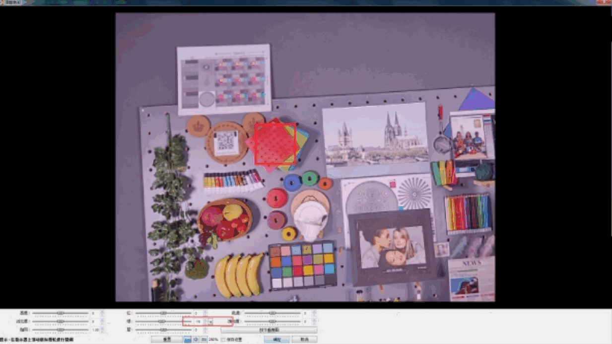
English source figure, PDF p.74, #595.
The red plastic sheet in the red box is orange, RGB = [212, 78, 80], and the G component is large compared to the target value of [212 63 79]. If you have more experience, you can skip the step of obtaining faststone and directly adjust the CCM to reduce the G component.

English source figure, PDF p.74, #597.
G' = a21*R + a22*G + a23*B
,

English source figure, PDF p.74, #599.
[a21,a22,a23] = [-0.2854,1.1496,0.1358]
Original correction factor:

English source figure, PDF p.74, #601.
a21
Since the red plastic sheet has the largest R component, reduce a21 and increase the absolute value of a22 to keep the row sum equal to 1.

English source figure, PDF p.74, #603.
a22

English source figure, PDF p.74, #605.
[a21,a22,a23] = [-0.385,1.2497,0.1358]
Adjusted correction factor:
English source figure, PDF p.74, #607.
Red plastic sheet: RGB = [208, 56, 76].
(2) Case 2 Yellowish green skin color:
English source figure, PDF p.75, #610.
The skin color in the red box is yellowish green, RGB = [216, 174, 124], where the G component is larger and the B component is small;

English source figure, PDF p.75, #612.
[[a21,a22,a23],[a31,a32,a33]] = [[-0.3192,1.6927,-0.3735],[0.0239,-0.5738,1.5499]]
Original correction factor:

English source figure, PDF p.75, #614.
a23

English source figure, PDF p.75, #615.
a22

English source figure, PDF p.75, #616.
a21
As in case 1, reduce G: greatly decrease a22 and increase a23, fine-tune a21.
English source figure, PDF p.75, #618.
Skin color at this time: RGB = [212, 169, 124];

English source figure, PDF p.75, #620.
a31
To increase B, since R is large, greatly increase a31; to preserve the row sum of 1, decrease a32 and a33.

English source figure, PDF p.75, #622.
a32

English source figure, PDF p.75, #623.
a33
English source figure, PDF p.75, #625.

English source figure, PDF p.76, #626.
[[a21,a22,a23],[a31,a32,a33]] = [[-0.3004,1.6375,-0.3371],[0.2127,-0.7294,1.5166]]
Adjusted correction coefficients are shown below.
Skin color at this location: RGB = [214, 169, 146].
4 Advanced color adjustment 3DLut
4.1 CCM VS 3DLut
The task of CCM is to make the colors under different light sources similar to the human eye, and the task of 3DLut is to adjust individual colors according to preferences. The advantages and disadvantages of both for color adjustment are as follows:
| CCM | 3DLut | |
|---|---|---|
| Pros | The color transition is natural and not easy to cause noise | It is easier to adjust the hue and saturation of a certain color; There can be no effect on unrelated colors |
| Cons | Modifying the CCM for a preference may cause other unsimilar colors to be affected; Color adjustment is more difficult | Since the current number of sampling points of 9x9x9 is too small, the color transition is easy to be unnatural, and adjusting the value will affect the denoising intensity of the pixel and introduce noise |
As for which option to choose, the actual project directly weighs color preference and transitions and noise.
4.2 Function description
3D lookup table 3 dimensional look-up-tables(3DLUT)
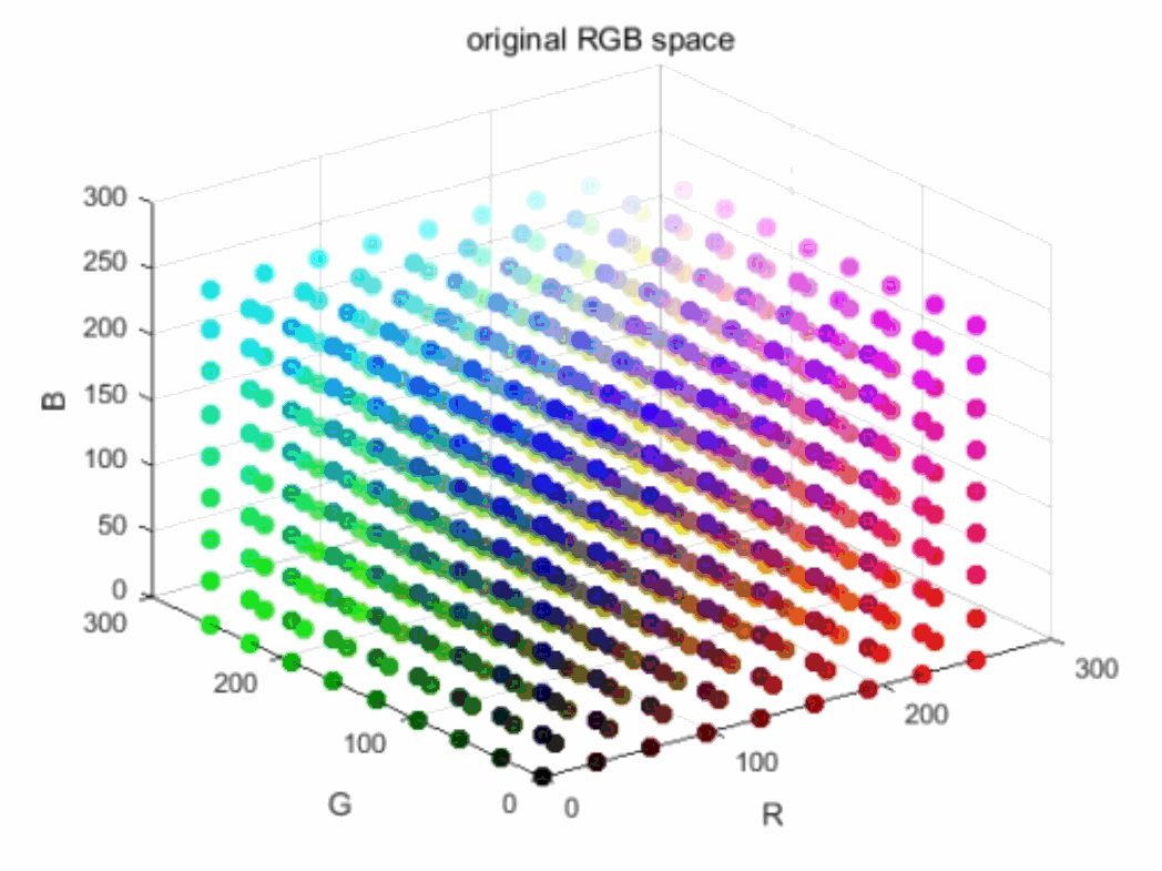
English source figure, PDF p.77, #636.
Figure 9x9x9 bypass 3DLUT illustration
Any color can be mapped independently to another value
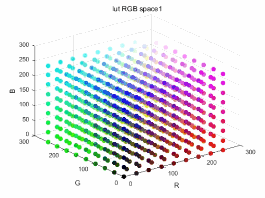
English source figure, PDF p.77, #639.
Figure 9x9x9 green enhanced 3dlut illustration
The 3D LUT on RK1109 is 9x9x9, and values not recorded in the table can be obtained by trilinear interpolation
4.3 Key parameters
The parameters are listed in the lut3d_calib node of the IQ json file, and the json parameters only take effect in automatic mode.
4.3.1 Enable control and mode selection
Under the Common node
| Parameter | Description |
|---|---|
| enable | 3DLUT enable switch, 1 means enable; The value is 0 or 1 |
| wbgain_tolerance | Tolerance of 3DLUT white balance gain change: When the difference of the statistical value of white balance gain is less than this threshold, the white balance gain can be considered to meet the stability condition of 3DLUT, and the value range is 0.0-1 |
| gain_tolerance | Tolerance of 3DLUT exposure gain change: When the difference of the statistical value of exposure gain is less than this threshold, the exposure gain can be considered to meet the stability condition of 3DLUT, and the value range is 0.0-1 |
4.3.2 Automatic 3DLUT parameters
Under the ALut3D node
| Parameter | Description |
|---|---|
| damp_en | 3DLUT smooth function switch, 1 means to use this function; The value is 0 or 1 |
4.3.2.1 3DLUT parameters
| Parameter | Description |
|---|---|
| Name | 3DLUT Name |
| awbGain | The corresponding standard white balance gain, generated by the calibration tool, is greater than 0 |
| gain | The exposure gain component of gain-alpha, decimal, value greater than 0 |
| alpha | gain-alpha of 3DLUT intensity component, decimal, value greater than 0 |
| look_up_table_r | R channel lookup table, value range: [0,1023] |
| look_up_table_g | G channel lookup table, value range: [0, 4095] |
| look_up_table_b | B channel lookup table, value range: [0,1023] |
4.4 3DLUT calibration and adjustment
RKISP 3D-LutTool converts the A-B (color channel) Cartesian coordinate system to C (saturation)-H (hue) polar coordinate system based on the LAB color model, and the input supports jpg/bmp/png/yuv/nv12 format. As shown in Figure 4.4-2, the origin O saturation is 0, the radial outward saturation increases, and the red arrow rotates counterclockwise to change the hue. Chapter 2.6 of Rockchip_IQ_Tools_Guide_ISP2x_CN, “3D-LUT Tools”, introduces its interface and how to use it.
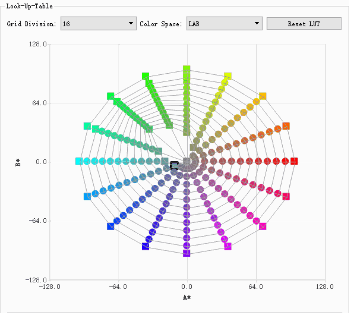
English source figure, PDF p.79, #654.
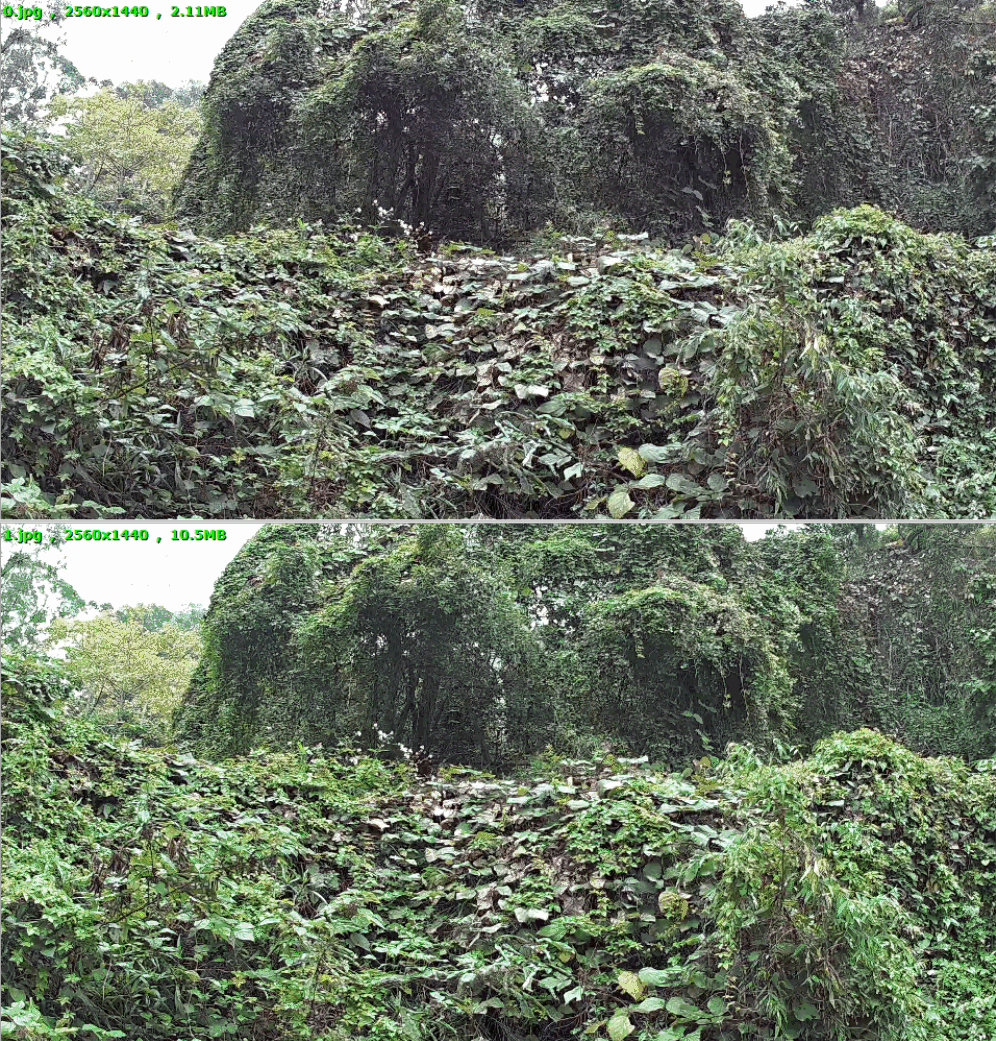
English source figure, PDF p.80, #655.
Figure 4.4-1 Enhanced green saturation
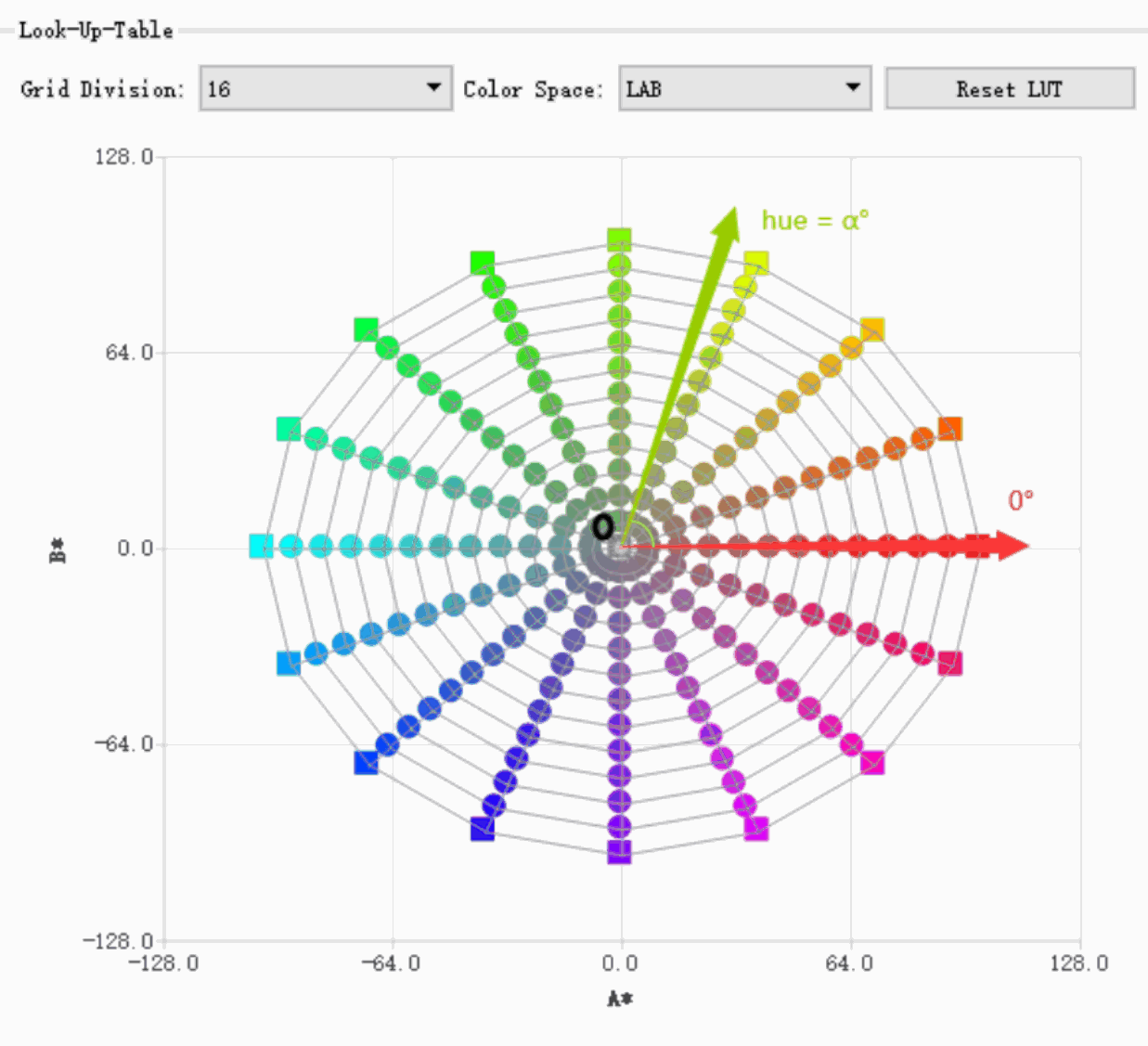
English source figure, PDF p.81, #657.
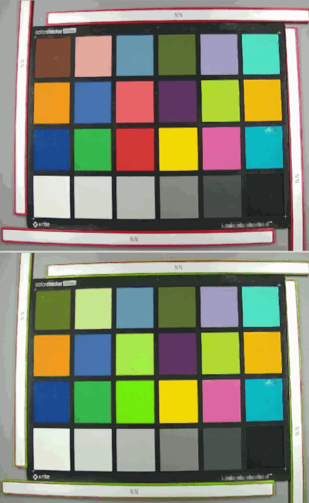
English source figure, PDF p.82, #658.
Figure 4.4-2 Change the red hue
4.4.1 Adjustment steps
1. Collect images, close 3DLUT and its post-modules (YNR/SHARP/CNR, etc.), in order to facilitate observation of whether 3DLUT introduces other effects, it is best to collect yuv images;
2. Import images, please refer to the description of “3D-LUT Tools” in Section 2.6 of Rockchip_IQ_Tools_Guide_ISP2x_CN;
3. Maintain the white balance, right-click the center origin, and the dot becomes a square to fix successfully;
4. Click the pixel to be adjusted on the right image display interface, which will be displayed in the left coordinate system;
5. Drag the mouse towards the target point, and note that the point near the point in the coordinate system needs to be smoothed;
6. After generating the 3DLUT parameters, apply the parameters in the colorful scene to observe whether the colors are as expected.
4.4.1.1 Note
Once the 3DLUT pre-module makes adjustments, especially affecting the color, the 3DLUT needs to be readjusted.
4.4.1.2 Case
Adjust the skin tone of your face:
(1) Select Grid Division (8,12,16), the larger the value, the higher the accuracy; Click the face area on the right image display interface to locate the left coordinate system;
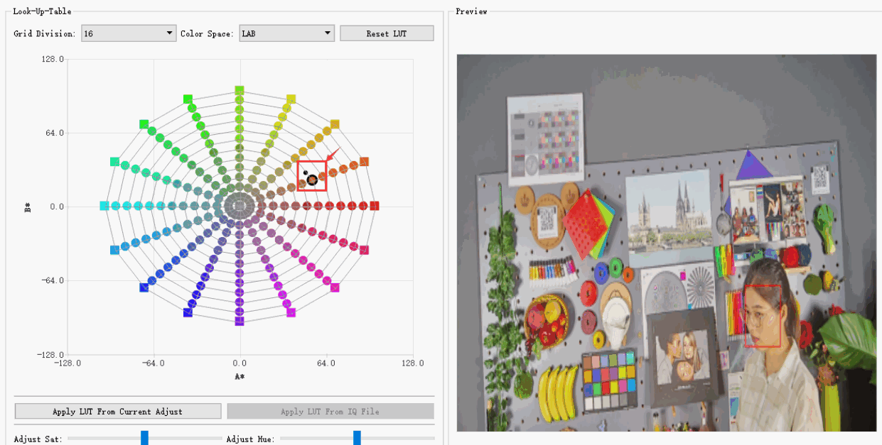
English source figure, PDF p.83, #672.
(2) The skin color is yellowish green, and it is necessary to shift the skin color anchor to the direction of the red hue and reduce the saturation, as shown in the (1) (2) logo in the figure; (3) The logo has been slightly adjusted for smoothing processing
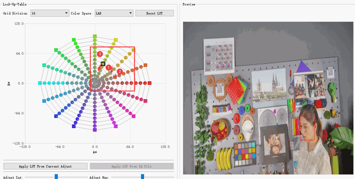
English source figure, PDF p.84, #674.
(3) Effect comparison:
English source figure, PDF p.84, #676.