
ArmSoM applicability
This document provides a usage guide for the PTP1588 functionality of the Ethernet GMAC interface on the Rockchip platform. This complete article follows the English V1.0.0 PDF (16 pages); no corresponding Chinese PDF was supplied. Chinese and Russian are complete translations of that source. All six figures in every language come from the English PDF, whose diagrams and instrument screenshots retain some Chinese labels.
This is an ArmSoM platform reference, not a board-validation report. The source product table below lists SoCs and says “ALL” for kernel versions; that is the source’s scope, not a verified statement that every kernel or ArmSoM board supports all features. Verify the exact board, Ethernet/PHY wiring, SDK/BSP, driver, clk_ptp_ref, PPS pinmux and available PTP clock. Section 4 separately describes RT-Thread on RK2118. No hardware commands, clock synchronization or patches were executed. Logs, waveforms and sub-microsecond results are source examples, not ArmSoM measurements.
| Source chipset | Source kernel scope |
|---|---|
| RK3588, RK3576, RK3568, RK3506, RV1126, RK2118 | ALL |
Source issues are retained and documented: the IPv6 address strings in §1.3, the name phy2sys in §2, the CST/UTC wording in §2.2, the gPTP expansion, and the initial large RMS log value. Do not silently treat these as verified configuration values. See the editorial notes for source pages and corrections limited to extraction/layout.
Editorial notes · ArmSoM · Rockchip Linux
1. PTP1588 Implementation Principle
PTP1588, formally known as the Precision Time Protocol standard for network measurement and control systems, fundamentally serves to synchronize all clocks in a distributed network with the most accurate clock. It defines a precise time protocol, PTP (Precision Time Protocol), for synchronizing clocks in standard Ethernet or other multicast-supporting terminal devices at the sub-microsecond level. IEEE’s PTP1588 is utilized in local distributed systems that require higher clock precision than what NTP offers. The GMAC controller supports PTP1588 versions v1 and v2.
Common PTP1588 synchronization process Delay Request-Response Mechanism:
1.1 Message Transmission and Reception Process for Delay Response Mechanism
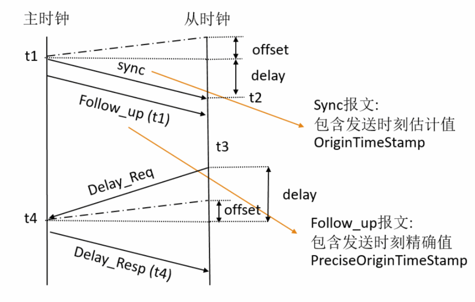
Delay Request-Response timing diagram — English PDF, p.4.
- The master device periodically broadcasts PTP synchronization messages to all its nodes. This message leaves the master device’s system at time t1. Record the time t1 when this packet leaves the Ethernet port on GMII or MII.
- The slave device receives the synchronization message and captures the accurate time t2 using its time reference.
- The master device sends a Follow_up message to the slave device, which contains the t1 information for later use. (Since the sync message cannot carry the precise message departure time, we encapsulate the precise sending timestamp of the sync message, t1, in the subsequent Follow_up message and send it to the slave clock).
- The slave device sends a Delay_Req message to the master device and records the accurate time t3 when this packet leaves the GMII or MII interface.
- The master device receives the message and captures the accurate time t4 when the message enters its system.
- The master device sends the t4 information to the slave device in the Delay_Resp message.
- The slave device uses the four values of t1, t2, t3, and t4 to synchronize its local timing reference to the master device’s timing reference.
1.2 Clock Skew & Network Latency
offset : Clock Skew (There is a time difference between the master and slave clocks, and the deviation value is the offset)
delay : Network Latency (The delay caused by the transmission of messages in the network)
The slave clock can obtain the master-slave clock skew offset and transmission delay delay through four precise timestamps t1, t2, t3, t4:
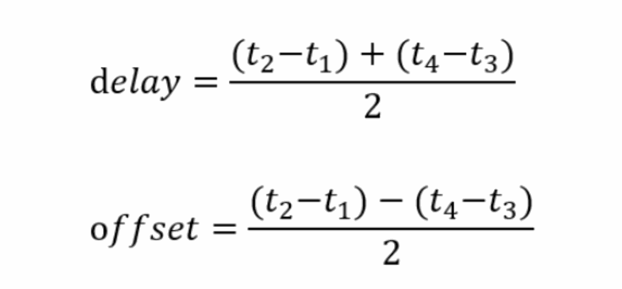
Delay and offset equations — English PDF, p.5.
delay  = ((t2 - t1) + (t4 - t3)) / 2
offset = ((t2 - t1) - (t4 - t3)) / 2
After the slave clock obtains the offset and delay, it can synchronize time by correcting the local clock.
1.3 PTP Messages
PTP Packets Over IPv4
IP Multicast Address (IEEE 1588 version 1), multicast IPv4 addresses allowed:
224.0.1.129224.0.1.130224.0.1.131224.0.1.132
IP Multicast Address (IEEE 1588 version 2):
- PTP Primary multicast address:
224.0.1.129 - PTP Pdelay multicast address:
224.0.0.107
PTP Frames Over IPv6 — the source lists these hexadecimal strings:
- PTP Primary multicast address:
FF0x:0:0:0:0:0:0:0:0:181 - PTP Pdelay multicast address:
FF02:0:0:0:0:0:0:0:0:6B
PTP Packets Over Ethernet
All PTP messages can use any of the following multicast addresses:
01-1B-19-00-00-0001-80-C2-00-00-0E
1.4 GMAC PTP1588 Working Principle
The system time generator module of GMAC PTP1588 is updated using the reference clock (clk_ptp_ref), which is the source for capturing snapshots (timestamps) of Ethernet data packets sent or received on the *GMII/RMII interface.
The system time consists of two parts, existing in the registers MAC_System_Time_Seconds and MAC_System_Time_Nanoseconds, with the nanoseconds field supporting the following two modes:
Digital rollover mode: In this mode, the maximum value of the nanoseconds field is 0x3B9A_C9FF, which is (10^9-1) nanoseconds.
Binary rollover mode: In this mode, the nanoseconds field flips and increments the field after 0x7FFF_FFFF, with an accuracy of approximately 0.466 ns per bit.
The system time is updated by setting the TSUPDT bit, which requires (adding or subtracting) the specified value in the MAC_System_Time_Seconds_Update and MAC_System_Time_Nanoseconds_Update registers before setting.
If only the system time is updated, this method has a relatively large jitter error, so a more precise method of updating the time is provided.
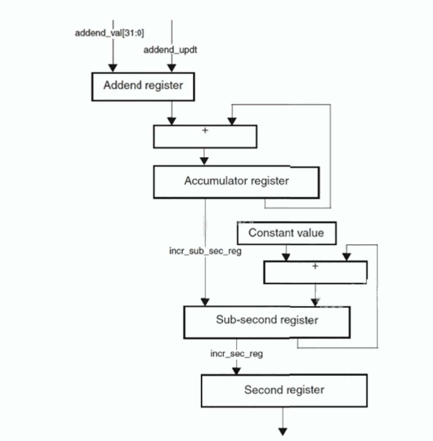
GMAC system-time accumulator and increment registers — English PDF, p.7.
As shown in the figure above, in the method of correcting the system time of GMAC PTP1588, the frequency offset or frequency drift of the clock (clk_ptp_ref) relative to the master clock (defined in IEEE 1588-2002) is corrected over a period of time. This helps to maintain linear time and does not introduce drastic changes (or large jitter) in the reference time between PTP synchronization message intervals. In this method, the accumulator adds the contents of the addend register, as shown in the figure above, and the arithmetic carry generated by the accumulator is used as a pulse to increase the system time counter. The accumulator is a 32-bit register that acts as a high-precision frequency multiplier or divider.
Generally, a default addend value is set here, for example, set to 0x80000000, so that after every two clk_ptp_ref clock cycles, the 32-bit accumulator will overflow; from the figure, it can be seen that if the accumulator overflows, the Sub-second register will increase by a configuration unit of the incr_sub_sec register, if it is a 100M clock, here the MAC_Sub_Second_Increment register value should be set to twice the clock cycle: 0x14; of course, this is for the digital mode, if it is binary mode, a transformation is needed. In digital mode, when it grows to 0x3B9A_C9FF, the corresponding Second register value increases by 1, indicating that time has accumulated by 1s; if it is binary mode, when it grows to 0x7FFF_FFFF, the Second register value increases by 1.
When performing PTP1588 synchronization, at each clk_ptp_ref clock cycle, the value of the addend register is added to the accumulator, and by changing the addend register value, the accumulation of Sub-second is affected, which can be simply considered as modifying the ptp clock, ultimately affecting the change in system time; software must calculate the frequency drift according to the synchronization message and update the addend addend register accordingly.
1.5 GMAC PTP1588 Timestamp Acquisition
From the perspective of the PTP1588 delay response mechanism’s message transmission and reception process, obtaining the precise time when messages are sent and received on the network card is crucial; in hardware implementation, GMAC saves the system timestamp data of the moment of sending and receiving at the specified memory while sending and receiving network packets, and this specified memory is the transmission and reception descriptor corresponding to its data packets, such as the following tx descriptor:
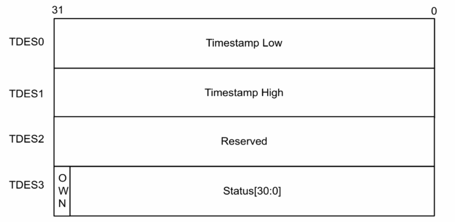
TX descriptor timestamp layout — English PDF, p.8.
| Descriptor word | Bits | Meaning |
|---|---|---|
| TDES0 | 31:0 | Timestamp Low |
| TDES1 | 31:0 | Timestamp High |
| TDES2 | 31:0 | Reserved |
| TDES3 | 31 | OWN |
| TDES3 | 30:0 | Status[30:0] |
Code snippet:
static inline void dwmac4_get_timestamp(void *desc, u32 ats, u64 *ts)
{
    struct dma_desc *p = (struct dma_desc *)desc;
    u64 ns;
    ns = le32_to_cpu(p->des0);
    /* convert high/sec time stamp value to nanosecond */
    ns += le32_to_cpu(p->des1) * 1000000000ULL;
    *ts = ns;
}
The types of messages for which hardware saves timestamps during reception and transmission need to be set in the MAC_Timestamp_Control register.
2. PTP1588 Testing
Check if hardware timestamps are supported using ethtool; for hardware timestamp support, the parameter list should include:
SOF_TIMESTAMPING_RAW_HARDWARE
SOF_TIMESTAMPING_TX_HARDWARE
SOF_TIMESTAMPING_RX_HARDWARE
root@linaro-alip:/# ethtool -T eth0
Time stamping parameters for eth0:
Capabilities:
        hardware-transmit (SOF_TIMESTAMPING_TX_HARDWARE)
        software-transmit (SOF_TIMESTAMPING_TX_SOFTWARE)
        hardware-receive (SOF_TIMESTAMPING_RX_HARDWARE)
        software-receive (SOF_TIMESTAMPING_RX_SOFTWARE)
        software-system-clock (SOF_TIMESTAMPING_SOFTWARE)
        hardware-raw-clock (SOF_TIMESTAMPING_RAW_HARDWARE)
PTP Hardware Clock: 0
Hardware Transmit Timestamp Modes:
        off
        on
Hardware Receive Filter Modes:
        none
        all
        ptpv1-l4-event
        ptpv1-l4-sync
        ptpv1-l4-delay-req
        ptpv2-l4-event
        ptpv2-l4-sync
        ptpv2-l4-delay-req
        ptpv2-event
        ptpv2-sync
Common testing software includes ptp4l, phy2sys provided by Linuxptp, and ptp4l synchronizes the PTP hardware clock with the master clock through hardware timestamps or synchronizes the system clock with the master clock through software timestamps; phc2sys achieves synchronization between the system clock and the network card hardware clock (only in hardware timestamp mode); other testing software includes ptpd2, etc.
2.1 ptp4l Testing
Slave:
ptp4l -i eth0 -m -H -s
Master:
ptp4l -i eth0 -m -H
ptp4l[420.071]: selected /dev/ptp0 as PTP clock
ptp4l[420.077]: port 1 (eth0): new foreign master 54e1ad.fffe.dfa454-1
ptp4l[424.077]: selected best master clock 54e1ad.fffe.dfa454
ptp4l[424.078]: port 1 (eth0): LISTENING to UNCALIBRATED on RS_SLAVE
ptp4l[425.084]: master offset -1466 s2 freq -20216 path delay 13117
ptp4l[425.084]: port 1 (eth0): UNCALIBRATED to SLAVE on MASTER_CLOCK_SELECTED
ptp4l[426.084]: master offset -6 s2 freq -19196 path delay 13117
ptp4l[427.085]: master offset 491 s2 freq -18701 path delay 13020
ptp4l[428.084]: master offset 330 s2 freq -18714 path delay 13026
ptp4l[429.084]: master offset 365 s2 freq -18580 path delay 13041
ptp4l[430.084]: master offset 116 s2 freq -18720 path delay 13050
ptp4l[431.084]: master offset 30 s2 freq -18771 path delay 13041
ptp4l[432.084]: master offset 24 s2 freq -18768 path delay 13032
ptp4l[433.084]: master offset 29 s2 freq -18756 path delay 13032
ptp4l[434.084]: master offset 39 s2 freq -18737 path delay 13032
ptp4l[435.084]: master offset -71 s2 freq -18836 path delay 13032
ptp4l[437.085]: master offset 201 s2 freq -18585 path delay 13015
ptp4l[438.085]: master offset -70 s2 freq -18796 path delay 13021
ptp4l[439.085]: master offset -30 s2 freq -18777 path delay 13041
ptp4l[440.085]: master offset 29 s2 freq -18727 path delay 13032
ptp4l[441.085]: master offset -41 s2 freq -18788 path delay 13037
ptp4l[442.085]: master offset -61 s2 freq -18820 path delay 13037
ptp4l[443.085]: master offset 54 s2 freq -18723 path delay 13007
ptp4l[444.085]: master offset -31 s2 freq -18792 path delay 13007
ptp4l[445.085]: master offset -6 s2 freq -18777 path delay 13007
ptp4l[446.085]: master offset 61 s2 freq -18711 path delay 13045
ptp4l[447.085]: master offset -89 s2 freq -18843 path delay 13045
ptp4l[448.085]: master offset 41 s2 freq -18740 path delay 13030
ptp4l[449.085]: master offset -4 s2 freq -18772 path delay 13030
ptp4l[450.085]: master offset -47 s2 freq -18817 path delay 13023
ptp4l[451.085]: master offset 5 s2 freq -18779 path delay 13026
ptp4l[452.085]: master offset 55 s2 freq -18727 path delay 13026
ptp4l[453.085]: master offset 93 s2 freq -18673 path delay 13023
ptp4l[454.085]: master offset -57 s2 freq -18795 path delay 13023
ptp4l[455.086]: master offset -32 s2 freq -18787 path delay 13023
ptp4l[456.085]: master offset 33 s2 freq -18732 path delay 13023
ptp4l[457.086]: master offset -26 s2 freq -18781 path delay 13037
ptp4l[458.086]: master offset -55 s2 freq -18817 path delay 13026
ptp4l[459.086]: master offset -5 s2 freq -18784 path delay 13026
ptp4l[460.086]: master offset -33 s2 freq -18813 path delay 13024
The master offset indicates the time difference between the master and slave endpoints, with the unit being nanoseconds (ns). s0 , s1 , s2 represent different states of the 1588 protocol, where s0 signifies not locked, s1 signifies syncing, and s2 signifies locked. freq denotes the frequency adjustment of the clock in parts per billion (ppb), and path delay represents the anticipated delay of the synchronization message sent from the master clock in nanoseconds, which can be measured via the E2E or P2P method, with E2E being the default.
2.2 Synchronize System Clocks
Synchronize the network card clock with the operating system:
Master Clock
sudo phc2sys -m -s CLOCK_REALTIME -c end0 -w &
sudo ptp4l -i end0 -m -H
Slave Clock
phc2sys -m -s eth0 -c CLOCK_REALTIME -w --step_threshold=1 &
ptp4l -i eth0 -m -H -s
Time on both boards before synchronization:
root@linaro-alip:/# date
July 8, 2024, Monday, 19:48:25 CST
root@buildroot:/# date
Thu Jan 1 00:14:02 UTC 1970
Time on both boards after synchronization (China Standard Time CST is exactly 8 time zones behind Coordinated Universal Time UTC): The source wording “behind” conflicts with the example below; this is retained as a source issue, not silently corrected.
root@linaro-alip:/# date
July 8, 2024, Monday, 19:51:52 CST
root@buildroot:/# date
Mon Jul 8 11:51:52 UTC 2024
2.3 gPTP Testing
gPTP, an abbreviation for general precise time protocol, is a derivative of the PTP protocol, also known as 802.1AS. The purpose of gPTP is to ensure that all nodes in a local area network are perfectly synchronized in time. The gPTP protocol is based on L2 layer propagation, which determines a characteristic that it can only propagate within a local area network.
Slave:
ptp4l -i eth0 -m -H -f ./gPTP.cfg --step_threshold=1 -s
Master:
ptp4l -i end0 -m -H -f ./gPTP.cfg --step_threshold=1
ptp4l[196.636]: selected /dev/ptp0 as PTP clock -f gPTP.cfg --step_threshold=1 -s
ptp4l[196.670]: port 1 (eth0): INITIALIZING to LISTENING on INIT_COMPLETE
ptp4l[196.671]: port 0 (/var/run/ptp4l): INITIALIZING to LISTENING on INIT_COMPLETE
ptp4l[196.671]: port 0 (/var/run/ptp4lro): INITIALIZING to LISTENING on INIT_COMPLETE
ptp4l[200.262]: port 1 (eth0): new foreign master 9ae370.fffe.1cb4e0-1
ptp4l[200.547]: selected local clock 568583.fffe.b70879 as best master
ptp4l[202.262]: selected best master clock 9ae370.fffe.1cb4e0
ptp4l[202.262]: port 1 (eth0): LISTENING to UNCALIBRATED on RS_SLAVE
ptp4l[202.942]: port 1 (eth0): UNCALIBRATED to SLAVE on MASTER_CLOCK_SELECTED
ptp4l[203.568]: rms 853264659523145600 max 1706529319046291712 freq -4554 +/- 1736 delay 15780 +/- 0
ptp4l[204.570]: rms 305 max 360 freq -5595 +/- 53 delay 15780 +/- 0
ptp4l[205.571]: rms 205 max 290 freq -5713 +/- 37 delay 15770 +/- 0
ptp4l[206.573]: rms 53 max 129 freq -5592 +/- 58 delay 15769 +/- 0
ptp4l[207.574]: rms 46 max 85 freq -5572 +/- 63 delay 15765 +/- 0
ptp4l[208.576]: rms 62 max 115 freq -5510 +/- 73 delay 15765 +/- 0
ptp4l[209.577]: rms 52 max 95 freq -5502 +/- 66 delay 15765 +/- 0
ptp4l[210.579]: rms 49 max 75 freq -5545 +/- 66 delay 15765 +/- 0
ptp4l[211.580]: rms 56 max 115 freq -5506 +/- 75 delay 15765 +/- 0
ptp4l[212.582]: rms 42 max 65 freq -5552 +/- 53 delay 15765 +/- 0
ptp4l[213.584]: rms 53 max 114 freq -5553 +/- 72 delay 15774 +/- 0
ptp4l[214.585]: rms 51 max 106 freq -5513 +/- 66 delay 15774 +/- 0
ptp4l[215.587]: rms 59 max 74 freq -5552 +/- 81 delay 15774 +/- 0
ptp4l[216.588]: rms 57 max 96 freq -5503 +/- 71 delay 15764 +/- 0
ptp4l[217.590]: rms 50 max 99 freq -5566 +/- 62 delay 15779 +/- 0
ptp4l[218.591]: rms 68 max 101 freq -5538 +/- 93 delay 15779 +/- 0
ptp4l[219.593]: rms 66 max 106 freq -5538 +/- 91 delay 15774 +/- 0
ptp4l[220.595]: rms 56 max 106 freq -5551 +/- 78 delay 15774 +/- 0
ptp4l[221.596]: rms 55 max 84 freq -5575 +/- 72 delay 15784 +/- 0
ptp4l[222.598]: rms 36 max 71 freq -5539 +/- 47 delay 15789 +/- 0
ptp4l[223.599]: rms 53 max 76 freq -5561 +/- 74 delay 15784 +/- 0
ptp4l[224.601]: rms 65 max 116 freq -5533 +/- 87 delay 15784 +/- 0
ptp4l[225.602]: rms 64 max 136 freq -5577 +/- 86 delay 15784 +/- 0
ptp4l[226.604]: rms 66 max 136 freq -5538 +/- 88 delay 15784 +/- 0
ptp4l[227.606]: rms 46 max 61 freq -5553 +/- 63 delay 15779 +/- 0
ptp4l[228.607]: rms 58 max 139 freq -5547 +/- 80 delay 15779 +/- 0
ptp4l[229.609]: rms 42 max 61 freq -5553 +/- 58 delay 15779 +/- 0
The root mean square (RMS) display of the offset is used here for a smoother representation.
3. PPS
3.1 Fixed PPS
PPS: Pulse-Per-Second; By default, GMAC operates in a fixed pulse-per-second output mode, indicating a 1-second interval. The frequency of the PPS output can be changed by setting the PPSCTRL0 field in the MAC_PPS_Control register. In this mode, as long as the iomux is properly configured, the PPS pulse output signal can be tested. The default value of PPSCTRL is 0000, with PPS outputting one pulse per second, and the pulse width being one clk_ptp_ref cycle.
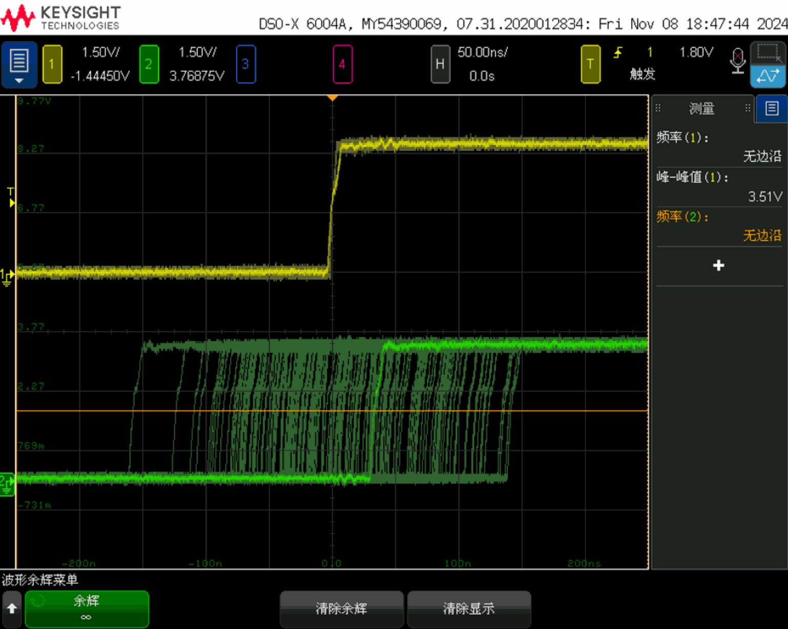
Source oscilloscope capture of PPS residual jitter — English PDF, p.13.
From the above diagram, it can be observed that after synchronization via PTP1588, the PPS signals output by two devices, as seen on an oscilloscope after a period of time, exhibit a jitter residue time that is essentially consistent with the master offset time difference results tested by ptp4l.
3.2 Binary Mode vs. Digital Mode
The previous sections have discussed that there are differences in system time updates under these two modes, and for PPS output, the frequency and duty cycle differ between these modes: For other values of PPSCTRL, the PPS output will generate clocks with the following frequencies:
| PPSCTRL | Binary rollover mode | Digital rollover mode |
|---|---|---|
| 0001 | 2 Hz | 1 Hz |
| 0010 | 4 Hz | 2 Hz |
| 0011 | 8 Hz | 4 Hz |
| 0100 | 16 Hz | 8 Hz |
| … | … | … |
| 1111 | 32.768 KHz | 16.384 KHz |
In binary flip mode, the PPS output (ptp_pps_o) has a duty cycle of 50% at these frequencies.
In digital flip mode, the PPS output frequency is an average. The actual clock frequency varies and is synchronized every second. For example:
When PPSCTRL = 0001, the PPS (1 Hz) low period is 537 milliseconds, and the high period is 463 milliseconds.
When PPSCTRL = 0010, PPS (2 Hz) is the following sequence: a clock with a 50% duty cycle and a period of 537 milliseconds, the second clock has a period of 463 milliseconds (268 milliseconds low, 195 milliseconds high).
When PPSCTRL = 0011, PPS (4 Hz) is the following sequence: three clocks with a 50% duty cycle and a period of 268 milliseconds, the fourth clock has a period of 195 milliseconds (134 milliseconds low, 61 milliseconds high).
Therefore, in digital mode, the PPS output period is not uniform; if a uniform period output is required, it needs to be configured in binary mode.
It should be noted that when PPSCTRL >= 1, the PPS signal here starts from a low level, which means it is aligned with the falling edge:
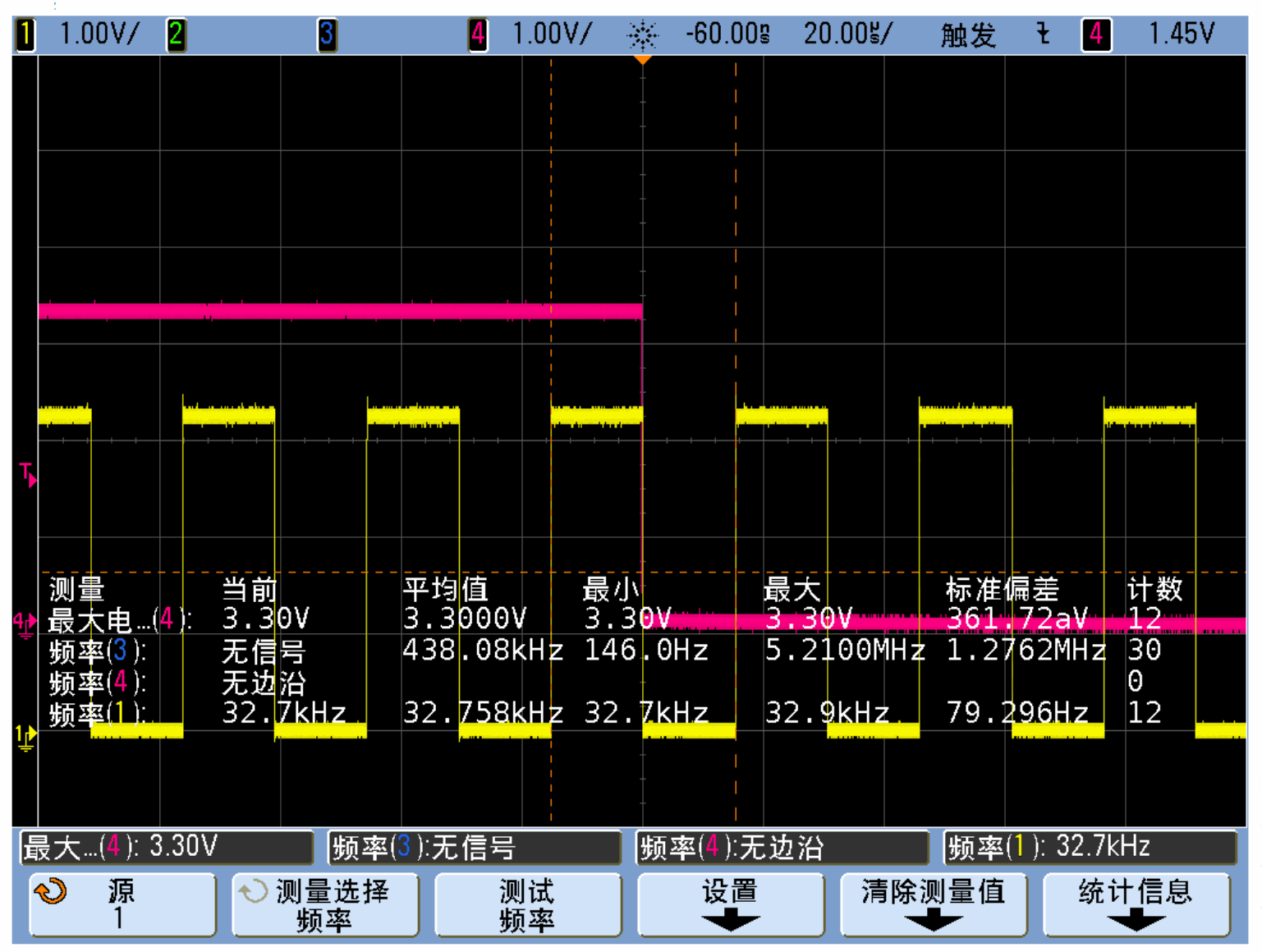
Source waveform showing PPS falling-edge alignment — English PDF, p.14.
3.3 Flex PPS
Compared to fixed PPS which outputs pulses at fixed seconds, flex PPS is more flexible with output options including start time, duty cycle, frequency, etc.
Enable PPS:
echo "0 0 0 1 1" > /sys/class/ptp/ptp0/period
Alternatively, you can set the PPS start time, for example, at 100s:
echo "0 100 0 1 1" > /sys/class/ptp/ptp0/period
After synchronizing the time on two devices, start running PPS
Run ptp4l in the background:
ptp4l -i eth0 -m -H &
ptp4l -i eth0 -m -H -s &
Agree to start PPS at the same moment, for example, at 200s, and input on both machines respectively:
echo "0 200 0 1 1" > /sys/class/ptp/ptp0/period
Both devices’ PPS signals are output to the same oscilloscope, and when the GMAC system time equals 200s, the PPS signals will be output simultaneously. The measured jitter time between the two is at the hundred ns level, which is consistent with the test data from ptp4l.
3.4 Chips Supporting PPS
Currently, among the chips that support PTP1588, all except RK3568 and RV1126 support the PPS function.
4. PTP1588 Functionality under RT-Thread
In addition to Linux, PTP1588 functionality can also be supported under RT-Thread, for example, the RK2118 chip uses RT-Thread.
5. Common Issues
5.1 TX Timeout
For certain versions of ptp4l that encounter the error “timed out while polling for tx timestamp,” you can modify the tx_timestamp_timeout parameter in the ptp4l.conf file to 400 . Then, specify the modified ptp4l.conf configuration file using the -f flag, or directly configure it with the command:
--tx_timestamp_timeout=400
5.2 4.19 Kernel Does Not Support Master Mode
Apply patch:
diff --git a/drivers/net/ethernet/stmicro/stmmac/stmmac_main.c b/drivers/net/ethernet/stmicro/stmmac/stmmac_main.c
index 0511062a9e0d..1e6078a17511 100644
--- a/drivers/net/ethernet/stmicro/stmmac/stmmac_main.c
+++ b/drivers/net/ethernet/stmicro/stmmac/stmmac_main.c
@@ -644,7 +644,8 @@ static int stmmac_hwtstamp_set(struct net_device *dev, struct ifreq *ifr)
 			config.rx_filter = HWTSTAMP_FILTER_PTP_V2_EVENT;
 			ptp_v2 = PTP_TCR_TSVER2ENA;
 			snap_type_sel = PTP_TCR_SNAPTYPSEL_1;
-			ts_event_en = PTP_TCR_TSEVNTENA;
+			if (priv->synopsys_id < DWMAC_CORE_4_10)
+				ts_event_en = PTP_TCR_TSEVNTENA;
 			ptp_over_ipv4_udp = PTP_TCR_TSIPV4ENA;
 			ptp_over_ipv6_udp = PTP_TCR_TSIPV6ENA;
 			ptp_over_ethernet = PTP_TCR_TSIPENA;