
Rockchip platform reference for the RK RT-Thread SDK, covering the chips listed in the source, including RK2108/RK2118. Matching ArmSoM board support is unconfirmed; no hardware validation was performed. Check SoC, SDK/BSP, RT-Thread version, controller type, IOMUX, wiring and voltage domains before adaptation. Commands and test results are source examples, not ArmSoM measurements; no hardware or flash operations were executed. Only a Chinese original is available; all four languages use Chinese source figures.
RK-KF-YF-080 · V1.4.0
1. Introduction
1.1 Supported devices
SPI NOR offers small packages, faster reads than other small nonvolatile memories, few pins and simple protocols. Common devices support 1/2/4-line transfers, resist bit flips, use byte addressing and read without a wait after command/address, enabling XIP (source: “Excute In Place”). RK RTOS SPI flash provides generic NOR interfaces and automatic XIP. SPI NAND uses the same controllers as NOR and is supported by the RT-Thread SDK. However, NAND needs FTL or an FTL-aware filesystem, consuming substantial RAM/code and offering only general stability. Supply stability during power loss is important, making batteryless MCU products vulnerable to abnormal power loss. The source therefore discourages NAND storage except limited read-only firmware expansion scenarios.
1.2 Host controllers
RK SPI flash can use FSPI, SFC or SPI.
- FSPI (Flexible Serial Peripheral Interface): SPI NOR/NAND and SPI PSRAM/SRAM; Standard SPI (single line), Dual, Quad, and Octal on some versions; SDR and DTR on some versions; XIP; built-in DMA.
- SFC (Serial Flash Controller): SPI NOR/NAND and SPI PSRAM/SRAM; Standard/Dual/Quad; SDR; built-in DMA.
- General SPI (Serial Peripheral Interface): SPI NOR/NAND and SPI PSRAM; Standard single-line SPI; SDR; external DMA.
1.3 NOR flash XIP
XIP (eXecute In Place) lets the CPU fetch instructions directly from mapped flash instead of copying code to RAM; execution addresses are the mapped addresses. NOR XIP is read-only, so only code and read-only information belong there. FSPI also allows DSP and other masters to access flash like read-only SRAM; see TRM FSPI. The NOR read API can use XIP reads (mapped access, no redundant register setup, prefetch, high efficiency) or CPU reads (configure controller and move FIFO data with the CPU). XIP reads are default. RT_SNOR_XIP_DATA_BEGIN sets their starting range; for 327680, [0:327680) uses CPU reads and [327680,end] uses XIP reads.
1.4 SPI flash driver framework
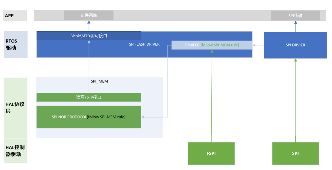
To adapt FSPI/SFC/SPI, the framework abstracts a controller layer. NOR has four layers: MTD; RTOS driver (device registration, registering controller/operations with HAL_SNOR, wrapping read/write/erase); HAL_SNOR protocol; controller. The source calls these “two” controller types despite listing three.
Chinese source figure (p.6)
FSPI implementation: drv_snor.c wraps FSPI HAL read/write as SPI_Xfer, registers the FSPI host and SPI_Xfer with HAL_SNOR, wraps its read/write/erase functions, and registers the OS device at MTD. hal_snor.c implements the NOR protocol; hal_fspi.c the controller. SPI implementation: drv_snor.c wraps SPI OS-driver read/write as SPI_Xfer, registers host and SPI_Xfer with HAL_SNOR, wraps protocol read/write/erase, and registers the MTD device. hal_snor.c implements the protocol; hal_spi.c provides the low-level controller, while SpiDevice.c registers and wraps the RTOS SPI driver. Notes:
- The implementations correspond directly to the diagram.
- RK SPI DMA resides in the OS driver. SPI also serves other devices and needs hardware-resource boundary protection. Therefore the flash framework must use the OS SPI interface, not attach directly to HAL hal_spi.c.
1.5 FSPI chip features
Only SoCs using open-source storage are listed.
| SOC | FSPI/SFC IO max rate | FSPI/SFC data io lines | Support XIP |
|---|---|---|---|
| RK2108/Pisces | 150MHz | x1\x2\x4 SDR | Y |
| RK2206 | 150MHz | x1\x2\x4 SDR | Y |
| RK2118 | SDR:133MHz DTR:80MHz |
x1\x2\x4 SDR x4 DDR with/without DQS x8 DDR with/without DQS |
Y |
AP support: Rockchip_Developer_Guide_Linux_Flash_Open_Source_Solution_CN.md. x1 is commonly Standard SPI, x2 Dual, x4 Quad, x8 Octal. Quad defaults to SDR; Octal defaults to DDR with DQS.
2. SPI NOR
2.1 Configuration
2.1.1 Framework
| Type | Memory | Controller driver | Flash framework |
|---|---|---|---|
| SPI NOR | SPI NOR | hal: lib/hal/src/hal_fspi.c RT-Thread: bsp/rockchip/commob/drv_snor.c |
hal: lib/hal/src/hal_snor.c |
RT-Thread HAL root: bsp/rockchip/common/hal. Supported NOR devices are in lib/hal/src/hal_snor.c; other support files are in the same directory. Match flash ID or package marking to source. Software identifies devices by ID and defaults to the controller’s widest supported transfer; reduce width using driver macros.
2.1.2 Driver configuration
First identify the physical SPI flash controller, then select the matching solution. Basic menuconfig entry:
RT-Thread rockchip common drivers  --->
    [*] Enable ROCKCHIP SPI NOR Flash
    (80000000) Reset the speed of SPI Nor flash in Hz
    [ ]   Set SPI Host DUAL IO Lines /* 如果 FSPI 主控仅预留 IO0~1,应使用 Dual mode */
            Choose SPI Nor Flash Adapter (Attach FSPI controller to SNOR) --->
Configuration definitions:
RT_USING_MTD_NOR=y
RT_USING_SNOR=y
RT_SNOR_SPEED=80000000 /* IO 接口速率 */
# RT_SNOR_DUAL_IO=n /* 默认不配置,Quad SPI 限制为 Duad SPI 使用 */
# RT_SNOR_XIP_DATA_BEGIN=0 /* 默认不配置,XIP 读接口实现起始地址,详细参考 “Nor Flash XIP 技术”说明 */
RT_USING_SNOR_FSPI_HOST=y /* FSPI 控制器方案 */
# RT_USING_SNOR_SFC_HOST=y /* SFC 控制器方案 */
# RT_USING_SNOR_SPI_HOST=y /* SPI 控制器方案 */
# RT_SNOR_SPI_DEVICE_NAME="spi2_0" /* SPI 控制器方案,指定目标控制器 */
RT_USING_DFS_MNTTABLE=y                # 启动 DFS mnt table 自动挂载支持
RT_USING_DFS_ELMFAT=y                  # 启用 elm FatFs
RT_DFS_ELM_MAX_SECTOR_SIZE=4096        # 设置 elm FatFs sector size,设定固定为 4KB
2.1.3 Partition table
See “Partition table configuration” in rockchip/Rockchip_Developer_Guide_RT-Thread_CN.md. NOR registers only partitions whose FLAG [8,9] property is 1, 2 or 3 as RT-Thread devices. For example root usually has Flag=0x305 and is registered as root block device.
2.1.4 Generate, parse and register partitions
Packed RK RT-Thread firmware places RK_PARTITION in the first 2KB of flash. Adjust partition information in setting.ini. After NOR initialization, the downloaded table is parsed and registered by snor_partition_init in drv_snor.c. Check device registration with:
msh />list_device
device          type         ref count
------- -------------------- ----------
root     Block Device         1            /* 分区名 root,分区类型 block 设备,Nor flash 支持 setting.ini 修改设定为 MTD 设备 */
snor     MTD Device           0            /* SPI Nor 根存储设备,分区读写最终接入到该 节点完成读写擦除 */
2.1.5 elm-fat and mounting
RT-Thread elm-fat support:
RT-Thread Components --->
    Device virtual file system  --->
    [*] Using device virtual file system
    [*]   Using mount table for file system /* 实现相应注册分区表,可实现分区上电自动挂 载 */
    [*]   Enable elm-chan fatfs /* fat 文件系统 */
        elm-chan's FatFs, Generic FAT Filesystem Module  --->
        (4096) Maximum sector size to be handled. /*对于 SPI Nor 产品必须修改为 4096 */
With CONFIG_RT_USING_DFS_MNTTABLE enabled, add partition registration in mnt.c, e.g. root at /:
const struct dfs_mount_tbl mount_table[] =
{
    {"root", "/", "elm", 0, 0},
    {0}
};
For a custom mount sequence use:
dfs_mount("root", "/", "elm", 0, 0)
Mount command:
mount root / elm
For elm-fat images follow ./bsp/rockchip/tools/mkroot.sh; key command: mkfs.fat.
2.2 XIP implementation notes
NOR supports XIP; an FSPI-based NOR solution enables it automatically. The following notes concern product use.
2.2.1 Enable XIP
FSPI flash configured as described in driver configuration enables XIP by default. To disable it, turn off “Enable FSPI XIP”.
2.2.2 Runtime XIP switching
The framework automatically switches XIP as needed; users need not call the switches. XIP off:
NOR erase/write takes a long time and is unsupported during XIP. For erase/write requests, including filesystem writes, software suspends XIP and switches FSPI to normal mode. XIP is unavailable during this interval. Suspend sequence:
- Notify every affected master to suspend XIP access.
- Disable global interrupts so an interrupt cannot execute CPU XIP code stored in NOR.
- Disable XIP.
XIP on: after erase/write completes and FSPI is idle, the driver restores XIP. Thus it remains enabled whenever no erase/write is running. Resume sequence:
- Enable XIP.
- Enable global interrupts (source literally says “global terminal”, retained as a source typo in the editorial notes).
- Notify all suspended devices to resume XIP. Entry points:
static rt_base_t snor_xip_suspend(void)
static void snor_xip_resume(rt_base_t level)
Summary: FSPI-driven NOR enables XIP by default. While FSPI is idle, capable devices can read NOR through mapped XIP memory. Erase/write disables XIP. Switching requires notifying devices to stop/resume access as above. Disabling XIP also disables global interrupts.
2.3 API examples
2.3.1 SNOR MTD byte device
See _at_snor_test in snor_test.c:
snor_device = (struct rt_mtd_nor_device *)rt_device_find("snor");
rt_mtd_nor_erase_block(snor_device, test_lba * block_size, block_size);
rt_mtd_nor_write(snor_device, test_lba * block_size, (const rt_uint8_t
*)pwrite32, block_size);
rt_mtd_nor_read(snor_device, test_lba * block_size, (rt_uint8_t *)pread32,
block_size);
snor is a byte device. rt_mtd_nor_erase_block uses Bytes, minimum alignment 4096Bytes (flash sector size). rt_mtd_nor_write/read use Bytes, minimum 1 Byte. RK partition table units are sectors (512B); convert units when accessing its information.
2.3.2 Partition MTD byte device
The NOR driver parses the table and registers selected partitions. A setting.ini MTD partition is registered as a byte device with the same APIs as SNOR MTD:
snor_device = (struct rt_mtd_nor_device *)rt_device_find("xxxx");
rt_mtd_nor_erase_block(snor_device, test_lba * block_size, block_size);
rt_mtd_nor_write(snor_device, test_lba * block_size, (const rt_uint8_t
*)pwrite32, block_size);
rt_mtd_nor_read(snor_device, test_lba * block_size, (rt_uint8_t *)pread32,
block_size);
2.3.3 Partition block device
A setting.ini Block partition is registered as a block device. Use standard RT-Thread read/write; the sector unit is 4KB.
2.4 Test driver
Include the following simple read/write tests during SPI flash development.
2.4.1 Driver configuration
RT-Thread bsp test case  --->
    RT-Thread Common Test case  --->
        [*] Enable BSP Common TEST
        [*]   Enable BSP Common SNOR TEST (NEW)
Successful configuration exposes snor_test in msh.
2.4.2 Test commands
Enter snor_test for help. All command units below are bytes.
1. snor_test write offset size
2. snor_test read offset size loop
3. snor_test erase offset
4. snor_test stress offset size loop
5. snor_test io_stress offset size loop width rw
6. snor_test pm_test
like:
        snor_test write 2097152 4096
        snor_test read 2097152 4096 2000
        snor_test erase 2097152
        snor_test stress 2097152 2097152 5000
        snor_test io_stress 2097152 2097152 5000 4
        snor_test pm_test
offset: byte offset within flash, not XIP address; decimal only, no hexadecimal. stress: incrementing-pattern data. io_stress width: sequence exercising IO states; width 4 is Quad-specific, width 8 Octal-specific. rw: 1 write-only (including erase), 2 read-only, 3 read/write.
2.4.3 Command examples
2.4.3.1 Read rate
msh >snor_test read 2097152 4096 2000
[SNOR TEST] read:  30219d00 + 0x0:0x00000200,0x0000000f,0x000000ff,0x00000000,
[SNOR TEST] read:  30219d00 + 0x10:0x000000ff,0x000000cc,0x000000c3,0x000000cc,
[SNOR TEST] read:  30219d00 + 0x20:0x000000c3,0x0000003c,0x000000cc,0x000000ff,
[SNOR TEST] read:  30219d00 + 0x30:0x000000fe,0x000000ff,0x000000fe,0x000000ef,
snor read speed: 143719 KB/s
2.4.3.2 Quad Flash signal test
Write-signal test:
snor_test io_stress 2097152 2097152 5000 4 1
Read-signal test:
snor_test io_stress 2097152 2097152 5000 4 2
2.4.3.3 Octal Flash signal test
Write-signal test:
snor_test io_stress 2097152 2097152 5000 8 1
Read-signal test:
snor_test io_stress 2097152 2097152 5000 8 2
2.5 Troubleshooting
How to check flash registration? Use list_device and look for snor.
“Init adapte error ret= -19” reports snor_adapt initialization status: -1 means NOR ID is 0xff, possibly poor soldering; inspect circuits/signals. -19 means the device is unsupported; ask RK engineering to add it. -22 means no SPI controller was found.
Does always-enabled XIP waste power? FSPI times out after idle and releases CS, allowing NOR low-power idle; the difference is not large.
Multiple XIP masters? The bus arbitrates and serializes requests; pending requests wait on the bus.
Frequent filesystem writes? Put code in SRAM/PSRAM and disable FSPI XIP, otherwise RTOS real-time behavior suffers. If code executes through XIP, minimize NOR erase/write.
Does filesystem reading disable XIP? No; the driver reads directly through XIP.
Can partitions be mounted without a flash partition table? No; the table must be stored at the beginning of flash. The current RK NOR driver only parses/mounts that stored table.
3. SPI NAND
3.1 Notes
3.1.1 RK SPI NAND storage
| Filesystem | Update |
|---|---|
| FATFS | USB / programmer / OTA |
3.2 Configuration
3.2.1 Framework
Chinese source figure (p.15)
| Type | Memory | Driver |
|---|---|---|
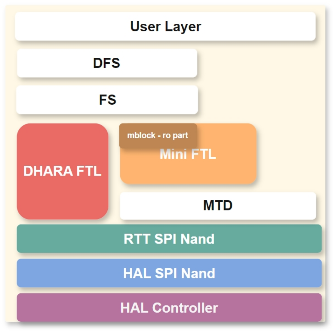
| SPI Nand | SPI Nand | DHARA FTL: bsp/rockchip/common/dhara/ RTT Mini FTL: bsp/rockchip/common/mini_ftl.c RTT SPI Nand: bsp/rockchip/common/drv_spinand.c HAL SPI Nand: lib/hal/src/hal_spinand.c HAL Controller: lib/hal/src/hal_fspi.c |
HAL root: bsp/rockchip/common/hal. Supported NAND devices are in lib/hal/src/hal_spinand.c; other device support is in that directory. Match flash ID or package marking. The driver detects ID and defaults to the controller’s widest supported IO; use macros to reduce width.
3.2.2 Driver configuration
Identify the actual SPI flash controller before selecting the solution. Basic menuconfig entry:
RT-Thread rockchip common drivers  --->
    [*] Enable ROCKCHIP SPI Nand Flash
    (80000000) Reset the speed of SPI Nand flash in Hz
    (y)   Support mini ftl
          Choose SPI Nor Flash Adapter (Attach FSPI controller to SNOR) --->
            Attach FSPI controller to SPINAND
    [ ]     extend fspi cs1 as SPINAND device (NEW)
Configuration definitions:
RT_USING_SNOR=n                        # 关闭 SPI Nor 驱动,通常外设仅有一种 SPI Flash
RT_USING_MTD_NAND=y
RT_USING_SPINAND=y
RT_SPINAND_SPEED=80000000              # IO 接口速率
RT_USING_SPINAND_FSPI_HOST=y           # FSPI 控制器方案
RT_USING_FTL=y                         # 启用 SPI Nand FTL 存储管理算法
RT_USING_DHARA=y                       # 启用 SPI Nand DHARA FTL 存储管理算法(与 Mini FTL 兼容)
RT_USING_DFS_MNTTABLE=y                # 启动 DFS mnt table 自动挂载支持
RT_USING_DFS_ELMFAT=y                  # 启用 elm FatFs
RT_DFS_ELM_MAX_SECTOR_SIZE=2048        # 设置 elm FatFs sector size,设定为 flash pagesize,通常为 2KB/4KB,参考颗粒手册
Also ensure XIP is disabled: XIP = ‘N’ in rtconfig.py.
3.2.3 FTL algorithms
3.2.3.1 DHARA FTL
Dhara (pronounced Dæ:ra) is open-source FTL for resource-constrained NAND systems, providing a mutable block interface with standard read/write.
- Wear leveling: erase counts of any two blocks differ by at most 1.
- GC speed can be tuned through the GC ratio at the expense of spare space.
- Logical-sector write/trim is atomic. Power loss rolls back to the last synchronization point; synchronization occurs at fixed intervals or explicitly on demand.
- With uniformly distributed bad blocks, all operations, including startup, have worst-case O(log n) time for chip size n. With DHARA enabled, partition block-device APIs use DHARA and sector size equals page size, typically 2KB/4KB. Limitation: by default only the entire NAND space is supported as FTL-managed space. Applications: one FSPI with NAND storing firmware/user data; one FSPI with CS0 NOR firmware (XIP disabled) and CSN1 NAND bulk user data; multiple FSPI with FSPI0 NOR firmware and FSPI1 NAND bulk data.
3.2.3.2 Mini FTL driver
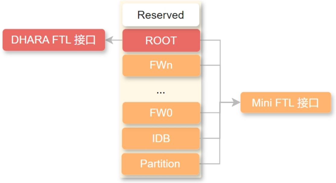
Mini FTL is not a standard FTL layer: it only provides basic bad-block management, mainly for partition firmware updates. It registers the partition named root as a same-name block device for a read-only filesystem.
3.2.4 Partition table configuration
3.2.4.1 Partition planning
Align partition start and size to 256KB for 128KB/256KB blocks. Reserve bad-block replacement space: except the table partition, small partitions need 1–2 flash blocks; partitions over 8MB need 1% spare. Reserve 2MB at the end for four bad-block-table blocks and one good backup-table block, compatible with 128KB/256KB blocks. A/B partitioning is recommended for OTA.
3.2.4.2 RK Partition extension
RK’s custom table resembles GPT but uses fewer resources and initializes faster, mainly for RV1107/8 and MCU. NAND defaults to registering the last partition as DHARA FTL-managed, usually root user partition for a filesystem.
3.2.4.3 GPT extension
The RK SDK also supports GPT partition extensions; the last partition defaults to DHARA FTL management, usually root for mounting a filesystem.
3.2.4.4 Custom ROOT partition
Without partition-table extensions, consider this single ROOT definition in drv_spinand.c:
RT_ROOT_PART_OFFSET
RT_ROOT_PART_SIZE
Units are sectors, 512B/sector. RK3308 RT-Thread build.sh provides an example of binding these definitions to the build script.
3.2.5 Parse and register partitions
After NAND initialization, parse the partition-table structure and register the last partition. Verify registration with:
msh />list_device
device          type         ref count
------- -------------------- ----------
userdata Block Device         0            /* DHARA FTL 实现,分区类型 block 设备, 通常为可读写 FAT 文件系统 */
root     Block Device         1            /* Mini FTL 实现,分区类型 block 设备,通 常为只读 FAT 文件系统 */
spinand  MTD Device           0            /* SPI Nand MTD 设备,分区读写最终接入到该 节点完成读写擦除 */
3.3 PC flashing tools
Use SocToolKit for Windows/Linux; matching mass-production tools exist. For OTA, A/B partitions are recommended.
Whether separate or packed images, NAND is ultimately updated partition by partition. RK Partition supports separate images but not Firmware.img. GPT supports separate images and update.img. Other extensions support only separate images.
3.4 API examples
Chinese source figure (p.19)
3.4.1 MTD byte-device basic API
See spinand_test in spinand_test.c:
mtd_dev = (struct rt_mtd_nor_device *)rt_device_find("spinand0");
rt_mtd_nand_check_block(mtd_dev, block);
rt_mtd_nand_erase_block(mtd_dev, block);
rt_mtd_nand_write(mtd_dev, page_addr + i, (const rt_uint8_t *)buffer, mtd_dev->page_size, RT_NULL, 0);
rt_mtd_nand_read(mtd_dev, page_addr + i, (rt_uint8_t *)buffer, mtd_dev->page_size, RT_NULL, 0);
spinand0 is a byte device. rt_mtd_nand_check_block returns true for bad, false for good blocks. The source names rt_mtd_nor_erase_block (units: blocks) and rt_mtd_nor_write/read (bytes, page-size alignment, usually 2KB/4KB; consult the flash manual) here; these NOR names are retained, not silently corrected. RK partition-table units are 512B sectors; convert appropriately.
3.4.2 Mini FTL: OTA/filesystem API
For OTA see mini_ftl_test_one_flash_block in spinand_test.c:
rt_uint32_t block_size = mtd_dev->pages_per_block * mtd_dev->page_size;
mtd_dev = (struct rt_mtd_nor_device *)rt_device_find("spinand0");
mini_ftl_erase(mtd_dev, addr, block_size);
mini_ftl_write(mtd_dev, buffer, addr, block_size);
mini_ftl_read(mtd_dev, buffer, addr, block_size);
mini_ftl_erase: bytes, blocksize alignment. mini_ftl_write: bytes, pagesize alignment; erase before writing. mini_ftl_read: bytes, pagesize alignment. For OTA align the buffer to block_size and complete erase/write/read verification in one call; erase the entire partition before updating elm FatFs. RK Partition information: rk_partition_list; GPT: dfs_part_list, currently without name info. With partition configuration, the named root partition is registered as root block device using Mini FTL for a read-only filesystem. Image flashing only; no online formatting.
3.4.3 DHARA FTL filesystem API
After partition configuration, the last partition becomes a same-name block device using DHARA FTL for a read/write filesystem. Image flashing and online formatting are supported.
3.5 Filesystems
3.5.1 elm FatFs support
Mini FTL block devices are read-only, mount FAT, take FAT firmware images and cannot format online. DHARA FTL block devices are read/write, mount FAT, require a FAT image wrapped as a DHARA firmware image, and support online formatting.
3.5.1.1 Mount partitions
With CONFIG_RT_USING_DFS_MNTTABLE add registration in mnt.c, e.g. root mounted at /:
const struct dfs_mount_tbl mount_table[] =
{
    {"root", "/", "elm", 0, 0},
    {0}
};
For a custom mount sequence:
dfs_mount("root", "/", "elm", 0, 0)
Mount command:
mount root / elm
3.5.1.2 Online partition formatting
mkfs -t elm userdata
root is read-only: mounting only, no online formatting.
3.5.1.3 Prepare elm-fat images offline
Follow ./bsp/rockchip/tools/mkroot.sh using mkfs.fat; set -S to page_size alignment, usually 2048/4096, according to the NAND manual.
3.5.1.4 Prepare DHARA images offline
DHARA tool:
Usage: ./dhara_utils <file_path> <flash_page_size> <num_blocks>
Example: offline FAT16 DHARA image, partition 504 blocks, NAND page size 2KB:
mkfs.vfat -F 16 -s 1 -S 2048 fat.img
./rkbin/dhara_utils fat.img 2 504
Output: fat.img.dhara.
For partition size see partition planning.
3.6 Test driver
3.6.1 Basic test configuration
RT-Thread bsp test case  --->
    RT-Thread Common Test case  --->
        [*] Enable BSP Common TEST
        [*]   Enable BSP Common SPINAND TEST (NEW)
Successful configuration exposes spinand_test in msh:
msh />spinand_test
1. spinand_test write <page_addr> <page_num>
2. spinand_test read <page_addr> <page_nun>
3. spinand_test erase <blk_addr>
4. spinand_test erase_all <blk_addr>
5. spinand_test stress <loop>
6. spinand_test bbt
7. spinand_test markbad <blk_addr>
8. spinand_test mini_ftl_test <byte_offset>
9. spinand_test part_list
like:
        spinand_test write 1024 1
        spinand_test read 1024 1
        spinand_test erase 16
        spinand_test erase_all 512
        spinand_test stress 5000
        spinand_test bbt
        spinand_test mini_ftl_test 67108864
        spinand_test part_list
3.6.2 flash_stress_test read/write stress
Objective: NAND stability under read/write stress. Prepare 10 target devices. Example test area: flash block offset 512 blocks, length 256 flash blocks.
- After boot run spinand_test stress 5000 512 256 and ensure uninterrupted power throughout the test.
- Record test logs.
- Pass if the device still operates normally after 24 hours; otherwise fail.
3.6.3 power_lost_test abnormal power loss
Objective: robustness against abnormal power loss, especially frequent in batteryless NAND products. Prepare 10 target devices. Method:
- Create a file-copy workload.
- Set power cycling to 2 seconds on, 3 seconds off: a 5-second cycle for 8 hours, about 5760 interruptions. After each interruption ensure the device powers up and runs the file-copy operation within 5 seconds.
- Record test logs.
- The source says to pass if operation remains normal after 24 hours, otherwise fail (this conflicts with the 8-hour duration above; both source values are retained). See the abnormal-power-loss reference source section.
3.7 Troubleshooting
3.7.1 RK2118 hangs with NAND enabled
Symptom:
FW data_offset:2048
FW data_size:  195584
FW load_addr:  0x1060800
copy 1090000 20a200 400
hash_256 fail! ret:-1
MemBoot fali!

SoftReset...
Try disabling XIP:
diff --git a/bsp/rockchip/rk2118/rtconfig.py b/bsp/rockchip/rk2118/rtconfig.py
index 2b6e696e2b..32b5117513 100644
--- a/bsp/rockchip/rk2118/rtconfig.py
+++ b/bsp/rockchip/rk2118/rtconfig.py
@@ -29,8 +29,8 @@ if os.getenv('RTT_EXEC_PATH'):
 #BUILD = 'debug'
 BUILD = 'release'

-XIP = 'Y'
-#XIP = 'N'
+#XIP = 'Y'
+XIP = 'N'
 if os.getenv('RTT_BUILD_XIP'):
     XIP = os.getenv('RTT_BUILD_XIP').upper()
3.7.2 NAND does not support RK Firmware.img updates
RK Firmware.img pads unused partition space with zeros except the last partition may be empty. With unchanged useful images, larger partitions greatly increase padding. The entire redundant data is carried in a single update. NAND allows factory bad blocks and requires free partition space for replacements. Thus a padded “one firmware” conflicts with NAND; even a single package must be unpacked and only useful per-partition images written. Programmers likewise cannot use one monolithic image.
3.7.3 NAND power-loss issues
Abnormal power-off bypasses normal deinitialization and can operate NAND at unstable voltage. Erase/program is mainly affected: erase takes several milliseconds, program hundreds of microseconds. A 3V3 device usually requires at least 2.7V; consult its manual. Two failure types: incomplete data being written; random errors when commands execute at unstable voltage. Filesystem recovery protects against incomplete-data corruption, though data may be lost. For unstable-voltage errors:
- PMIC monitors VCC IO, typically resets CPU below 2.91V so the host stops issuing erase/write. Peripheral discharge should sustain operating voltage about 1ms to finish the last operation.
- Reset IC works similarly, commonly detecting below 2.93V.
- RK NPOR similarly monitors VCCIO and resets CPU at its threshold. Prefer battery-backed or constant-power NAND products. Otherwise improve hardware so PMIC/Reset IC/RK NPOR detects falling VCC IO and resets CPU before low-voltage erase/write commands occur.
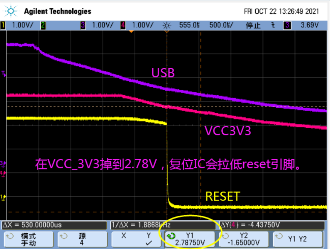
Add capacitance following RK demo boards so NAND VCCIO flash stays valid, normally for tBERS (block erase time). Avoid power loss during flash operations. Provide backups/recovery: dual firmware copies; critical data in a read-only filesystem; recovery for damaged read/write partitions so normal operation or OTA remains possible. To validate timing, run power_lost_test in the real product/workload and capture VCC3V3/RESETn at power loss:
Chinese source figure (p.25)
The oscilloscope must show RESETn/Reset-IC trigger (Y1), VCC3V3 falling to 2V7 (Y2), and ΔY1Y2 time. Repeat and analyze the smallest interval. On RV1106 and similar RKNPOR designs RESETn is internal, so approximate it with a GPIO held high plus an external pull-down: CPU reset disables the GPIO and the pull-down drives it low. That transition approximates CPU reset timing.
3.7.4 NAND power-loss reference code
#include <dfs_file.h>

static void readwrite_test(void *param)
{
    int fd, size, len = 2048, loops = 0;
    char *pwrite, *pread;

    pwrite = rt_malloc(len);
    if (!pwrite) {
        rt_kprintf("malloc pwrite failed\n");
        return;
    }
    pread = rt_malloc(len);
    if (!pread) {
        rt_kprintf("malloc pread failed\n");
        rt_free(pwrite);
        return;
    }

    fd = open("/file_stress.txt", O_RDWR | O_CREAT);
    if (fd < 0)
    {
        rt_kprintf("%s open file failed\n", __func__);
        goto err_open;
    }

    while (1) {
        rt_kprintf("file_stress, loops=%d\n", loops);
        rt_memset(pwrite, loops & 0xff, len);

        lseek(fd, 0, SEEK_SET);
        write(fd, pwrite, len);
        lseek(fd, 0, SEEK_SET);
        size = read(fd, pread, len);
        if (size < 0) {
            break;
        }

        if (rt_memcmp(pwrite, pread, len)) {
            rt_kprintf("%s compare failed, %x\n", __func__, pread[0]);
            break;
        }
        loops++;
    }

    close(fd);
err_open:
    rt_free(pread);
    rt_free(pwrite);
}

void file_stress(void)
{
    rt_thread_t thread;

    thread = rt_thread_create("file_stresss",
                              readwrite_test, NULL,
                              2048,
                              21, 20);
    rt_thread_startup(thread);
}