
This is a Rockchip RK3399 platform reference for the source-described Linux kernel 4.4 and later BSPs. TCPM and EXTCON configurations apply only to the kernel ranges stated in each section. It does not establish support on every ArmSoM board: verify the actual SoC, DP/Type-C wiring, PD controller, firmware, device tree and BSP patches. No ArmSoM hardware validation was performed; logs, values and testing capabilities are source examples or source statements.
Source: Rockchip RK3399 Developer Guide DisplayPort, V1.0.0 in both languages, with different cover dates. Source inconsistencies are retained; register examples are not validated board-specific commands. Editorial notes. ArmSoM documentation · Rockchip
1. Introduction to RK3399 Platform DP
1.1 Functional Overview
The functional parameters of the RK3399 DP interface are as follows:
| Function | RK3399 |
|---|---|
| Version | 1.2 |
| SST | Support |
| MST | Not Supported |
| DSC | Not Supported |
| Max Resolution | 4K@60Hz |
| Main-Link Lanes | 1/2/4 lanes |
| Main-Link Rate | 5.4/2.7/1.62 Gbps/lane |
| AUX_CH | 1 M |
| Color Format | RGB/YUV444/YUV422 |
| Color Depth | 8/10 bit |
| Type-C Support | Support |
| I2S | Support |
| SPDIF | Support |
1.2 Connection Relationship between DP, VOP, and PHY
The connection relationship between DP, VOP, and PHY is as follows:
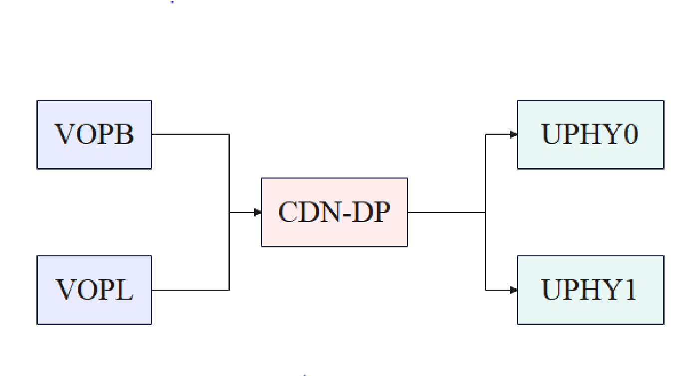
The RK3399 has 2 VOPs: VOPB and VOPL. DP can choose one of these VOPs as the input source. When VOPB is selected as the input source for DP, the maximum supported resolution is 4096x2160@60Hz. When VOPL is selected as the input source, the maximum supported resolution is 2650x1600@60Hz. The output of DP has 2 options: UPHY0 and UPHY1. However, only one of them can be used at a time; they cannot be used simultaneously.
1.3 Code Path
Kernel Driver Code
# Controller
drivers/gpu/drm/rockchip/cdn-dp-core.c
drivers/gpu/drm/rockchip/cdn-dp-core.h

drivers/gpu/drm/rockchip/cdn-dp-link-training.c
drivers/gpu/drm/rockchip/cdn-dp-reg.c
drivers/gpu/drm/rockchip/cdn-dp-reg.h
# PHY
drivers/phy/rockchip/phy-rockchip-typec.c
Reference DTS Configuration
arch/arm64/boot/dts/rockchip/rk3399-evb-ind.dtsi
1.4 Driver Loading
The RK3399 DP has an internal micro-controller. Before DP starts working, it will first load the firmware, which is stored at:
/lib/firmware/rockchip/dptx.bin
You can determine whether the driver has loaded successfully through the following log:
[  3.796582][ T9] rockchip-drm display-subsystem: bound fec00000.dp (ops
cdn_dp_component_ops)
2. Functional Configuration
DP and USB3.0 share the PHY (Type-C PHY). There are 2 configuration modes depending on the interface: one is DP Alt Mode (Type-C), and the other one is Legacy Mode (DP standard port).
For these 2 methods, the software flow differences are minimal. For the Type-C interface, the PD chip driver based on the TCPM architecture will notify the PHY driver and DP controller driver of the HPD information through callback functions. For the DP standard port, a virtual PD driver will notify the PHY driver and DP controller of the HPD information detected on the HPD pin.
The lane and pin mappings on the Type-C PHY are as follows:
| PHY Lanes/Module Pins | Type-C Receptacle Pins |
|---|---|
| Lane0 (tx_p/m_ln_0) | TX1+/TX1- (pins A2/A3) |
| Lane1 (tx_rx_p/m_ln_1) | RX1+/RX1- (pins B11/B10) |
| Lane2 (tx_rx_p/m_ln_2) | RX2+/RX2- (pins A11/A10) |
| Lane3 (tx_p/m_ln_3) | TX2+/TX2- (pins B2/B3) |
The mapping of USB and DP lanes on the Type-C PHY supports the C, D, E, etc., mappings listed in DP Alt Mode (Normal):
| PHY Lanes | C | D | E |
|---|---|---|---|
| 0 | ML2 | SSTX | ML2 |
| 1 | ML3 | SSRX | ML3 |
| 2 | ML0 | ML0 | ML0 |
| 3 | ML1 | ML1 | ML1 |
The flip mapping is as follows:
| PHY Lanes | C | D | E |
|---|---|---|---|
| 0 | ML0 | ML0 | ML0 |
| 1 | ML1 | ML1 | ML1 |
| 2 | ML2 | SSTX | ML2 |
| 3 | ML3 | SSRX | ML3 |
Additionally, the polarity of the Type-C normal and flip sides is controlled by the PHY itself.
2.1 DP Alt Mode (Type-C)
Taking the use of only UPHY0 as an example, the configuration to enable the DP interface is as follows:
&cdn_dp {
   status = "okay";
   phys = <&tcphy0_dp>;

};
Specify the VOP used by DP, for example, specifying VOPB as follows:
&dp_in_vopb {
   status = "okay";
};


&dp_in_vopl {
   status = "disabled";
};
Enable PHY:
&tcphy0 {
   status = "okay";
};
In Linux Kernel 5.10 and later kernel versions, the PD chip driver uses the TCPM architecture and registers callback functions to notify HPD information. In Linux Kernel 4.19 and earlier kernel versions, the PD chip uses the EXTCON mechanism to notify HPD information. There are differences in the DTS and PD chip-related configurations under these two different mechanisms.
2.1.1 TCPM Architecture Configuration
Taking the use of only UPHY0 as an example, the Type-C PHY needs to be enabled and configured as follows:
&tcphy0 {
   status = "okay";

   /* DP related config */

   svid = <0xff01>;
   /* DP related config */

   orientation-switch;
   port {
      #address-cells = <1>;
      #size-cells = <0>;
      tcphy0_orientation_switch: endpoint@0 {
         reg = <0>;
         remote-endpoint = <&usbc0_orien_sw>;
      };


      /* DP related config */
      tcphy_dp_altmode_switch: endpoint@1 {
         reg = <1>;
         remote-endpoint = <&dp_mode_sw>;
      };
      /* DP related config */
   };
};
In the above configuration:
svid: For DP, it is a fixed value of 0xff01.
tcphy_dp_altmode_switch: Used to match the PD chip node.
The Type-C interface needs to configure the lane and HPD state through Type-C CC detection and PD negotiation. Therefore, it is also necessary to configure the PD chip:
usb_con: connector {
   compatible = "usb-c-connector";
   label = "USB-C";

   data-role = "dual";
   power-role = "dual";
   try-power-role = "sink";
   op-sink-microwatt = <1000000>;
   sink-pdos =
      <PDO_FIXED(5000, 2500, PDO_FIXED_USB_COMM)>;
   source-pdos =
      <PDO_FIXED(5000, 1500, PDO_FIXED_USB_COMM)>;

   /* DP related config */
   displayport = <&cdn_dp>;

   altmodes {

      #address-cells = <1>;
      #size-cells = <0>;

      altmode@0 {
         reg = <0>;
         svid = <0xff01>;
         vdo = <0xffffffff>;

      };
   };
   /* DP related config */

   ports {
      #address-cells = <1>;
      #size-cells = <0>;

      port@0 {
         reg = <0>;
         usbc0_orien_sw: endpoint {
           remote-endpoint = <&tcphy0_orientation_switch>;

         };
      };
      /* DP related config */
      port@1 {
         reg = <1>;
         dp_mode_sw: endpoint {
           remote-endpoint = <&tcphy_dp_altmode_switch>;
         };
      };
      /* DP related config */
   };
};
displayport is configured as the DP node.
In the altmode@0 node, svid is fixedly configured as 0xff01, and vdo is fixedly configured as 0xffffffff.
dp_mode_sw is used to match the Type-C PHY node.
Note: The currently supported PD chips are fusb302 and hub311. The driver for fusb302 is located at /drivers/usb/typec/tcpm/fusb302.c, and the driver for hub311 is located at /drivers/usb/typec/tcpm/tcpci_husb311.c.
2.1.2 EXTCON Mechanism Configuration
Taking the use of only UPHY0 as an example, the Type-C PHY needs to be enabled and configured as follows:
&tcphy0 {
   extcon = <&fusb0>;
   status = "okay";

};
DP controller configuration:
&cdn_dp {
   status = "okay";
   extcon = <&fusb0>;

   phys = <&tcphy0_dp>;
};
In the above configuration:
extcon is the reference to the PD chip node.
2.2 Legacy Mode (DP Standard Port)
Taking the use of only UPHY0 as an example, the configuration to enable the DP interface is the same as for the Type-C interface. The configuration to enable the DP interface is as follows:
&cdn_dp {
   status = "okay";
   phys = <&tcphy0_dp>;

};
Specify the VOP used by DP, for example, specifying VOPB as follows:
&dp_in_vopb {
   status = "okay";
};


&dp_in_vopl {
   status = "disabled";
};
Enable PHY:
&tcphy0 {
   status = "okay";
};
When using the standard interface, in Linux Kernel 5.10 and later kernel versions, GPIO interrupts are used to obtain HPD information. In Linux Kernel 4.19 and earlier kernel versions, the EXTCON mechanism is used to notify HPD information, and a specific patch is required to notify the information on the HPD pin through callback functions or the EXTCON mechanism.
2.2.1 DP Lane Mapping
On the Type-C PHY interface, the relationship between PHY lanes and Type-C pins is as follows:
| PHY Lanes/Module Pins | Type-C Receptacle Pins |
|---|---|
| Lane0 (tx_p/m_ln_0) | TX1+/TX1- (pins A2/A3) |
| Lane1 (tx_rx_p/m_ln_1) | RX1+/RX1- (pins B11/B10) |
| Lane2 (tx_rx_p/m_ln_2) | RX2+/RX2- (pins A11/A10) |
| Lane3 (tx_p/m_ln_3) | TX2+/TX2- (pins B2/B3) |
PHY Lanes only support two fixed mapping methods, which are 4-lane mapping and 2-lane mapping.
The 4-lane mapping is as follows:
| PHY Lanes | DP lane |
|---|---|
| Lane0 | ML2 |
| Lane1 | ML3 |
| Lane2 | ML0 |
| Lane3 | ML1 |
The 2-lane mapping is as follows:
| PHY Lanes | DP lane |
|---|---|
| Lane2 | ML0 |
| Lane3 | ML1 |
2.2.2 HPD Notification Patch
In Linux Kernel 4.19 and earlier kernel versions, the EXTCON mechanism is used to notify HPD information, and the following patch needs to be applied:
diff --git a/drivers/extcon/Kconfig b/drivers/extcon/Kconfig
index de15bf55895b..90f5c9eb956c 100644
--- a/drivers/extcon/Kconfig

+++ b/drivers/extcon/Kconfig
@@ -158,4 +158,10 @@ config EXTCON_USBC_CROS_EC
       Say Y here to enable USB Type C cable detection extcon support when
       using Chrome OS EC based USB Type-C ports.
@@ -158,4 +158,10 @@ config EXTCON_USBC_CROS_EC
       Say Y here to enable USB Type C cable detection extcon support when
       using Chrome OS EC based USB Type-C ports.

+config EXTCON_PD_VIRTUAL
+     tristate "Rockchip Virtual PD EXTCON support"
+     depends on GPIOLIB
+     help
+       Say Y here to enable Rockchip Virtual PD extcon support.
+

 endif
diff --git a/drivers/extcon/Makefile b/drivers/extcon/Makefile
index 0888fdeded72..d8dd2b8647c9 100644
--- a/drivers/extcon/Makefile
+++ b/drivers/extcon/Makefile
@@ -22,3 +22,4 @@ obj-$(CONFIG_EXTCON_RT8973A) += extcon-rt8973a.o
 obj-$(CONFIG_EXTCON_SM5502) += extcon-sm5502.o
 obj-$(CONFIG_EXTCON_USB_GPIO) += extcon-usb-gpio.o
 obj-$(CONFIG_EXTCON_USBC_CROS_EC) += extcon-usbc-cros-ec.o
+obj-$(CONFIG_EXTCON_PD_VIRTUAL) += extcon-pd-virtual.o
diff --git a/drivers/extcon/extcon-pd-virtual.c b/drivers/extcon/extcon-pd-virtual.c
new file mode 100755

index 000000000000..94095beff9ff
--- /dev/null
+++ b/drivers/extcon/extcon-pd-virtual.c
@@ -0,0 +1,578 @@
+/*
+ * Copyright (c) 2024, Fuzhou Rockchip Electronics Co., Ltd
+ *
+ * This program is free software; you can redistribute it and/or modify it
+ * under the terms and conditions of the GNU General Public License,
+ * version 2, as published by the Free Software Foundation.
+ */
+
+#include <linux/init.h>

+#include <linux/kernel.h>
+#include <linux/module.h>
+#include <linux/platform_device.h>
+#include <linux/slab.h>
+#include <linux/extcon-provider.h>
+#include <linux/gpio.h>
+#include <linux/of_gpio.h>
+#include <linux/irq.h>
+#include <linux/interrupt.h>
+#include <linux/delay.h>
+
+struct virtual_pd {

+     struct extcon_dev *extcon;
+     struct gpio_desc *gpio_vbus_5v;
+     struct gpio_desc *gpio_hdmi_5v;
+     struct gpio_desc *gpio_irq;
+     struct device *dev;
+     bool flip;
+     bool usb_ss;
+     bool enable;
+     u8 mode;
+     int irq;
+     int enable_irq;
+     int plug_state;
+     struct work_struct work;
+     struct workqueue_struct *virtual_pd_wq;
+     spinlock_t irq_lock;
+     struct delayed_work irq_work;

+     int shake_lev;
+};
+
+static const unsigned int vpd_cable[] = {
+     EXTCON_USB,
+     EXTCON_USB_HOST,
+     EXTCON_USB_VBUS_EN,
+     EXTCON_CHG_USB_SDP,
+     EXTCON_CHG_USB_CDP,
+     EXTCON_CHG_USB_DCP,
+/*
+ FIXME: There's no real pd phy, control the charging is very

+ dangerous, just rely on the BC detection. We don't use slow
+ and fast.
+*/
+     EXTCON_CHG_USB_SLOW,
+     EXTCON_CHG_USB_FAST,
+     EXTCON_DISP_DP,
+     EXTCON_NONE,
+};
+
+enum vpd_mode {
+     VPD_DFP = 0,
+     VPD_UFP,
+     VPD_DP,

+     VPD_DP_UFP,
+};
+
+static void vpd_set_vbus_enable(struct virtual_pd *vpd, bool enable)
+{
+     extcon_set_state(vpd->extcon, EXTCON_USB_VBUS_EN, enable);
+     extcon_sync(vpd->extcon, EXTCON_USB_VBUS_EN);
+     if (vpd->gpio_vbus_5v)
+           gpiod_set_raw_value(vpd->gpio_vbus_5v, enable);
+}
+
+static void vpd_extcon_notify(struct virtual_pd *vpd, bool flip, bool usb_ss,

+                     bool dfp, bool ufp, bool dp)
+{
+     union extcon_property_value property;
+
+     property.intval = flip;
+     extcon_set_property(vpd->extcon, EXTCON_USB,
+                    EXTCON_PROP_USB_TYPEC_POLARITY, property);
+     extcon_set_property(vpd->extcon, EXTCON_USB_HOST,
+                    EXTCON_PROP_USB_TYPEC_POLARITY, property);
+     extcon_set_property(vpd->extcon, EXTCON_DISP_DP,
+                    EXTCON_PROP_USB_TYPEC_POLARITY, property);
+
+     property.intval = usb_ss;
+     extcon_set_property(vpd->extcon, EXTCON_USB,
+                    EXTCON_PROP_USB_SS, property);
+     extcon_set_property(vpd->extcon, EXTCON_USB_HOST,

+                    EXTCON_PROP_USB_SS, property);
+     extcon_set_property(vpd->extcon, EXTCON_DISP_DP,
+                    EXTCON_PROP_USB_SS, property);
+     extcon_set_state(vpd->extcon, EXTCON_USB, ufp);
+     extcon_set_state(vpd->extcon, EXTCON_USB_HOST, dfp);
+     extcon_set_state(vpd->extcon, EXTCON_DISP_DP, dp);
+     extcon_sync(vpd->extcon, EXTCON_USB);
+     extcon_sync(vpd->extcon, EXTCON_USB_HOST);
+     extcon_sync(vpd->extcon, EXTCON_DISP_DP);
+}
+
+static void vpd_extcon_notify_set(struct virtual_pd *vpd)

+{
+     bool flip = vpd->flip, usb_ss = vpd->usb_ss;
+     bool dfp = 0, ufp = 0, dp = 0;
+
+     switch (vpd->mode) {
+     case VPD_DFP:
+           dfp = 1;
+           break;
+     case VPD_DP:
+           dp = 1;
+           dfp = 1;
+           break;
+     case VPD_DP_UFP:

+           dp = 1;
+           ufp = 1;
+           break;
+     case VPD_UFP:
+           /* fall through */
+     default:
+           ufp = 1;
+           break;
+     }
+
+     vpd_set_vbus_enable(vpd, !ufp);
+     vpd_extcon_notify(vpd, flip, usb_ss, dfp, ufp, dp);

+}
+
+static void vpd_extcon_notify_clr(struct virtual_pd *vpd)
+{
+     vpd_set_vbus_enable(vpd, 0);
+     vpd_extcon_notify(vpd, vpd->flip, vpd->usb_ss, 0, 0, 0);
+}
+
+static ssize_t vpd_flip_show(struct device *dev,
+                    struct device_attribute *attr, char *buf)
+{
+     struct virtual_pd *vpd = dev_get_drvdata(dev);
+
+     return sprintf(buf, "%d\n", vpd->flip);
+}
+

+static ssize_t vpd_flip_store(struct device *dev,
+                     struct device_attribute *attr,
+                     const char *buf, size_t count)
+{
+     struct virtual_pd *vpd = dev_get_drvdata(dev);
+
+     if (vpd->enable)
+           goto out;
+
+     if (strncmp(buf, "1", 1) == 0)
+           vpd->flip = true;
+     else

+           vpd->flip = false;
+out:
+     return count;
+}
+static DEVICE_ATTR(flip, S_IWUSR | S_IRUSR, vpd_flip_show, vpd_flip_store);
+
+static ssize_t vpd_ss_show(struct device *dev,
+                   struct device_attribute *attr, char *buf)
+{
+     struct virtual_pd *vpd = dev_get_drvdata(dev);
+
+     return sprintf(buf, "%d\n", vpd->usb_ss);
+}

+
+static ssize_t vpd_ss_store(struct device *dev,
+                     struct device_attribute *attr,
+                     const char *buf, size_t count)
+{
+     struct virtual_pd *vpd = dev_get_drvdata(dev);
+
+     if (vpd->enable)
+           goto out;
+
+     if (strncmp(buf, "1", 1) == 0)
+           vpd->usb_ss = true;

+     else
+           vpd->usb_ss = false;
+out:
+     return count;
+}
+static DEVICE_ATTR(ss, S_IWUSR | S_IRUSR, vpd_ss_show, vpd_ss_store);
+
+static ssize_t vpd_mode_show(struct device *dev,
+                   struct device_attribute *attr, char *buf)
+{
+     struct virtual_pd *vpd = dev_get_drvdata(dev);
+
+     return sprintf(buf, "%d\n", vpd->mode);
+}
+
+static ssize_t vpd_mode_store(struct device *dev,

+                     struct device_attribute *attr,
+                     const char *buf, size_t count)
+{
+     struct virtual_pd *vpd = dev_get_drvdata(dev);
+
+     if (vpd->enable)
+           goto out;
+
+     if (strncmp(buf, "0", 1) == 0)
+           vpd->mode = VPD_DFP;
+     else if (strncmp(buf, "2", 1) == 0)
+           vpd->mode = VPD_DP;

+     else if (strncmp(buf, "3", 1) == 0)
+           vpd->mode = VPD_DP_UFP;
+     else
+           vpd->mode = VPD_UFP;
+out:
+     return count;
+}
+static DEVICE_ATTR(mode, S_IWUSR | S_IRUSR, vpd_mode_show, vpd_mode_store);
+
+static ssize_t vpd_enable_show(struct device *dev,
+                    struct device_attribute *attr, char *buf)
+{
+     struct virtual_pd *vpd = dev_get_drvdata(dev);

+
+     return sprintf(buf, "%d\n", vpd->enable);
+}
+
+static ssize_t vpd_enable_store(struct device *dev,
+                     struct device_attribute *attr,
+                     const char *buf, size_t count)
+{
+     struct virtual_pd *vpd = dev_get_drvdata(dev);
+
+     if (strncmp(buf, "1", 1) == 0) {
+           if (vpd->enable)

+                 goto out;
+           vpd->enable = true;
+           vpd_extcon_notify_set(vpd);
+     } else {
+           if (!vpd->enable)
+                 goto out;
+           vpd->enable = false;
+           vpd_extcon_notify_clr(vpd);
+     }
+out:
+     return count;
+}
+static DEVICE_ATTR(enable, S_IWUSR | S_IRUSR, vpd_enable_show, vpd_enable_store);
+
+static struct attribute *vpd_attributes[] = {
+     &dev_attr_flip.attr,

+     &dev_attr_ss.attr,
+     &dev_attr_mode.attr,
+     &dev_attr_enable.attr,
+     NULL
+};
+
+static const struct attribute_group vpd_attr_group = {
+     .attrs = vpd_attributes,
+};
+
+void vpd_irq_disable(struct virtual_pd *vpd)
+{

+     unsigned long irqflags = 0;
+
+     spin_lock_irqsave(&vpd->irq_lock, irqflags);
+     if (!vpd->enable_irq) {
+           disable_irq_nosync(vpd->irq);
+           vpd->enable_irq = 1;
+     } else {
+           dev_warn(vpd->dev, "irq have already disabled\n");
+     }
+     spin_unlock_irqrestore(&vpd->irq_lock, irqflags);
+}
+
+void vpd_irq_enable(struct virtual_pd *vpd)

+{
+     unsigned long irqflags = 0;
+
+     spin_lock_irqsave(&vpd->irq_lock, irqflags);
+     if (vpd->enable_irq) {
+           enable_irq(vpd->irq);
+           vpd->enable_irq = 0;
+     }
+     spin_unlock_irqrestore(&vpd->irq_lock, irqflags);
+}
+
+static void virtual_pd_work_func(struct work_struct *work)

+{
+     struct virtual_pd *vpd;
+
+     vpd = container_of(work, struct virtual_pd, work);
+     dev_info(vpd->dev, "%s %d =====>\n",__FUNCTION__,__LINE__);
+}
+
+static void extcon_pd_delay_irq_work(struct work_struct *work)
+{
+     struct virtual_pd *vpd =
+           container_of(work, struct virtual_pd, irq_work.work);
+     int lev;
+
+     lev = gpiod_get_raw_value(vpd->gpio_irq);
+
+     if(vpd->shake_lev != lev) {

+           vpd_irq_enable(vpd);
+           return;
+     }
+
+     switch(vpd->plug_state) {
+           case 1:
+                 if(lev==0) {
+                       vpd->enable = false;
+                       vpd_extcon_notify_clr(vpd);
+                       vpd->plug_state=0;
+                 }
+                 break;

+           case 0:
+                 if(lev==1) {
+                       vpd->enable = true;
+                       vpd_extcon_notify_set(vpd);
+                       vpd->plug_state=1;
+                 }
+                 break;
+           default:
+                 break;
+     }
+     vpd_irq_enable(vpd);
+}
+

+static irqreturn_t dp_det_irq_handler(int irq, void *dev_id)
+{
+     struct virtual_pd *vpd = dev_id;
+     int lev;
+
+     lev=gpiod_get_raw_value(vpd->gpio_irq);
+     vpd->shake_lev = lev;
+     schedule_delayed_work(&vpd->irq_work, msecs_to_jiffies(10));
+     vpd_irq_disable(vpd);
+     return IRQ_HANDLED;
+}
+

+static void vpd_extcon_init(struct virtual_pd *vpd)
+{
+     struct device *dev = vpd->dev;
+     u32 tmp = 0;
+     int ret = 0;
+
+     ret = device_property_read_u32(dev, "vpd,init-flip", &tmp);
+     if (ret < 0)
+           vpd->flip = 0;
+     else
+           vpd->flip = tmp;
+     dev_dbg(dev, "init-flip = %d\n", vpd->flip);
+
+     ret = device_property_read_u32(dev, "vpd,init-ss", &tmp);
+     if (ret < 0)
+           vpd->usb_ss = 0;

+     else
+           vpd->usb_ss = tmp;
+     dev_dbg(dev, "init-ss = %d\n", vpd->usb_ss);
+
+     ret = device_property_read_u32(dev, "vpd,init-mode", &tmp);
+     if (ret < 0)
+           vpd->mode = 0;
+     else
+           vpd->mode = tmp;
+     dev_dbg(dev, "init-mode = %d\n", vpd->flip);
+     if(gpiod_get_raw_value(vpd->gpio_irq)) {
+           vpd_extcon_notify_set(vpd);

+           vpd->plug_state=1;
+     }
+}
+
+static int vpd_extcon_probe(struct platform_device *pdev)
+{
+     struct virtual_pd *vpd;
+     struct device *dev = &pdev->dev;
+     int ret = 0;
+
+     dev_info(dev, "%s: %d start\n", __func__, __LINE__);
+
+     vpd = devm_kzalloc(dev, sizeof(*vpd), GFP_KERNEL);

+     if (!vpd)
+           return -ENOMEM;
+
+     vpd->dev = dev;
+     dev_set_drvdata(dev, vpd);
+     vpd->enable = 1;
+
+     vpd->extcon = devm_extcon_dev_allocate(dev, vpd_cable);
+     if (IS_ERR(vpd->extcon)) {
+           dev_err(dev, "allocat extcon failed\n");
+           return PTR_ERR(vpd->extcon);
+     }

+
+     ret = devm_extcon_dev_register(dev, vpd->extcon);
+     if (ret) {
+           dev_err(dev, "register extcon failed: %d\n", ret);
+           return ret;
+     }
+
+     vpd->gpio_vbus_5v = devm_gpiod_get_optional(dev,"vbus-5v",
+                                     GPIOD_OUT_LOW);
+     if (IS_ERR(vpd->gpio_vbus_5v)) {
+           dev_warn(dev, "maybe miss named GPIO for vbus-5v\n");
+           vpd->gpio_vbus_5v = NULL;
+     } else
+           gpiod_set_raw_value(vpd->gpio_vbus_5v, 0);
+
+     vpd->gpio_hdmi_5v = devm_gpiod_get_optional(dev,"hdmi-5v",

+                                     GPIOD_OUT_LOW);
+     if (IS_ERR(vpd->gpio_hdmi_5v)) {
+           dev_warn(dev, "maybe miss named GPIO for gpio_hdmi_5v\n");
+           vpd->gpio_hdmi_5v = NULL;
+     }
+
+     vpd->gpio_irq = devm_gpiod_get_optional(dev,"dp-det",
+                                     GPIOD_OUT_LOW);
+     if (IS_ERR(vpd->gpio_irq)) {
+           dev_warn(dev, "maybe miss named GPIO for dp-det\n");
+           vpd->gpio_irq = NULL;
+     }

+
+     ret = extcon_set_property_capability(vpd->extcon, EXTCON_USB,
+                                EXTCON_PROP_USB_TYPEC_POLARITY);
+     if (ret) {
+           dev_err(dev,
+                 "set USB property capability failed: %d\n", ret);
+           return ret;
+     }
+
+     ret = extcon_set_property_capability(vpd->extcon, EXTCON_USB_HOST,
+                                EXTCON_PROP_USB_TYPEC_POLARITY);
+     if (ret) {
+           dev_err(dev,

+                 "set USB_HOST property capability failed: %d\n",
+                 ret);
+           return ret;
+     }
+
+     ret = extcon_set_property_capability(vpd->extcon, EXTCON_DISP_DP,
+                                EXTCON_PROP_USB_TYPEC_POLARITY);
+     if (ret) {
+           dev_err(dev,
+                 "set DISP_DP property capability failed: %d\n",
+                 ret);
+           return ret;

+     }
+
+     ret = extcon_set_property_capability(vpd->extcon, EXTCON_USB,
+                                EXTCON_PROP_USB_SS);
+     if (ret) {
+           dev_err(dev,
+                 "set USB USB_SS property capability failed: %d\n",
+                 ret);
+           return ret;
+     }
+
+     ret = extcon_set_property_capability(vpd->extcon, EXTCON_USB_HOST,
+                                EXTCON_PROP_USB_SS);
+     if (ret) {
+           dev_err(dev,
+                 "set USB_HOST USB_SS property capability failed: %d\n",

+                 ret);
+           return ret;
+     }
+
+     ret = extcon_set_property_capability(vpd->extcon, EXTCON_DISP_DP,
+                                EXTCON_PROP_USB_SS);
+     if (ret) {
+           dev_err(dev,
+                 "set DISP_DP USB_SS property capability failed: %d\n",
+                 ret);
+           return ret;
+     }

+
+     ret = extcon_set_property_capability(vpd->extcon, EXTCON_CHG_USB_FAST,
+                                EXTCON_PROP_USB_TYPEC_POLARITY);
+     if (ret) {
+           dev_err(dev,
+                 "set USB_PD property capability failed: %d\n", ret);
+           return ret;
+     }
+
+     vpd_extcon_init(vpd);
+     INIT_DELAYED_WORK(&vpd->irq_work, extcon_pd_delay_irq_work);
+
+     vpd->irq=gpiod_to_irq(vpd->gpio_irq);

+     dev_info(dev, "%s %d =====>%d\n",__FUNCTION__,__LINE__,vpd->irq);
+     if (vpd->irq){
+           ret = devm_request_threaded_irq(dev,
+                                  vpd->irq,
+                                  NULL,
+                                  dp_det_irq_handler,
+                                  //IRQF_TRIGGER_HIGH | IRQF_ONESHOT,
+                                  IRQF_TRIGGER_FALLING | IRQF_TRIGGER_RISING |
+                                  IRQF_ONESHOT,
+                                  NULL,
+                                  vpd);
+     } else {

+           dev_err(dev,"gpio can not be irq !\n");
+     }
+
+     vpd->virtual_pd_wq = create_workqueue("virtual_pd_wq");
+     INIT_WORK(&vpd->work, virtual_pd_work_func);
+     ret = sysfs_create_group(&dev->kobj, &vpd_attr_group);
+     if (ret < 0)
+           dev_warn(dev, "attr group create failed\n");
+
+     dev_info(dev, "%s: %d sussess\n", __func__, __LINE__);
+
+     return 0;
+}
+
+static int vpd_extcon_remove(struct platform_device *pdev)
+{

+     return 0;
+}
+
+#ifdef CONFIG_PM_SLEEP
+static int vpd_extcon_suspend(struct device *dev)
+{
+     struct virtual_pd *vpd = dev_get_drvdata(dev);
+
+     int lev=0;
+     lev = gpiod_get_raw_value(vpd->gpio_irq);
+     cancel_delayed_work_sync(&vpd->irq_work);
+     vpd_irq_disable(vpd);

+     if (vpd->gpio_hdmi_5v)
+           gpiod_set_raw_value(vpd->gpio_hdmi_5v, 0);
+     return 0;
+}
+
+static int vpd_extcon_resume(struct device *dev)
+{
+     struct virtual_pd *vpd = dev_get_drvdata(dev);
+     if (vpd->gpio_hdmi_5v) {
+           gpiod_set_raw_value(vpd->gpio_hdmi_5v, 1);
+           msleep(800);
+     }
+     vpd_irq_enable(vpd);

+     return 0;
+}
+#endif
+
+static SIMPLE_DEV_PM_OPS(vpd_extcon_pm_ops,
+                 vpd_extcon_suspend, vpd_extcon_resume);
+
+static const struct of_device_id vpd_extcon_dt_match[] = {
+     { .compatible = "linux,extcon-pd-virtual", },
+     { /* sentinel */ }
+};
+MODULE_DEVICE_TABLE(of, usb_extcon_dt_match);

+
+static struct platform_driver vpd_extcon_driver = {
+     .probe      = vpd_extcon_probe,
+     .remove     = vpd_extcon_remove,
+     .driver     = {
+           .name = "extcon-pd-virtual",
+           .pm   = &vpd_extcon_pm_ops,
+           .of_match_table = vpd_extcon_dt_match,
+     },
+};
+
+static int __init __vpd_extcon_init(void)
+{
+          return platform_driver_register(&vpd_extcon_driver);
+}
+

+static void __exit __vpd_extcon_exit(void)
+{
+          platform_driver_unregister(&vpd_extcon_driver);
+}
+
+module_init(__vpd_extcon_init);
+module_exit(__vpd_extcon_exit);
+
+MODULE_LICENSE("GPL");
+MODULE_AUTHOR("rockchip");
+MODULE_DESCRIPTION("Virtual Typec-pd extcon driver");
In addition to the above patch, the following compilation option needs to be enabled:
CONFIG_EXTCON_PD_VIRTUAL=y
2.2.3 DTS Configuration
Taking the use of only UPHY0 as an example, if the hardware design is as follows, the DP lane mapping is shown in the following figure:
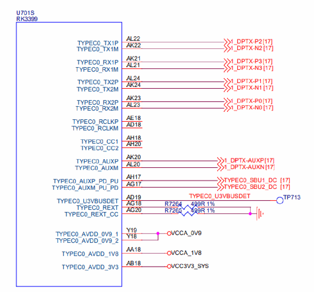
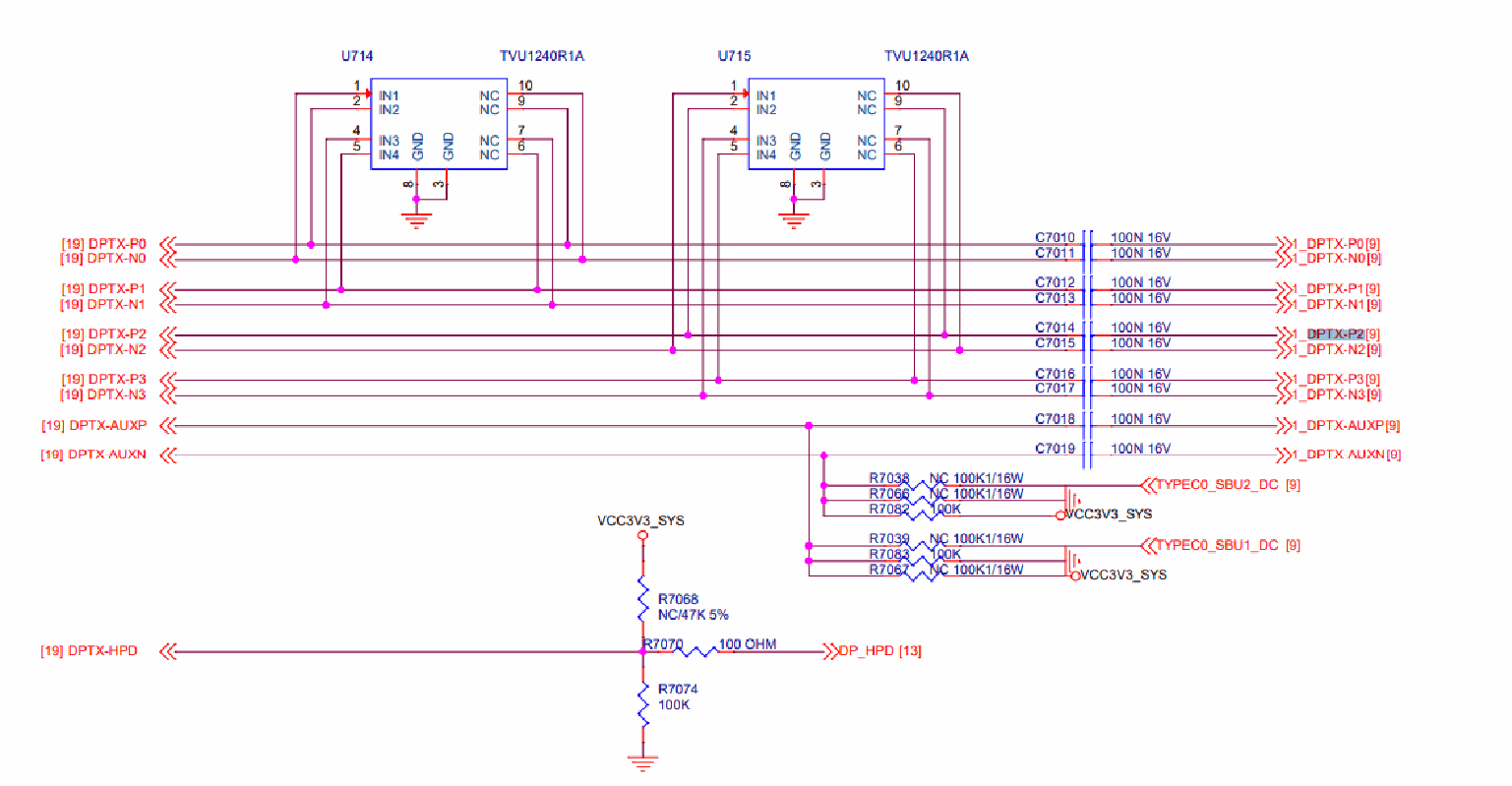
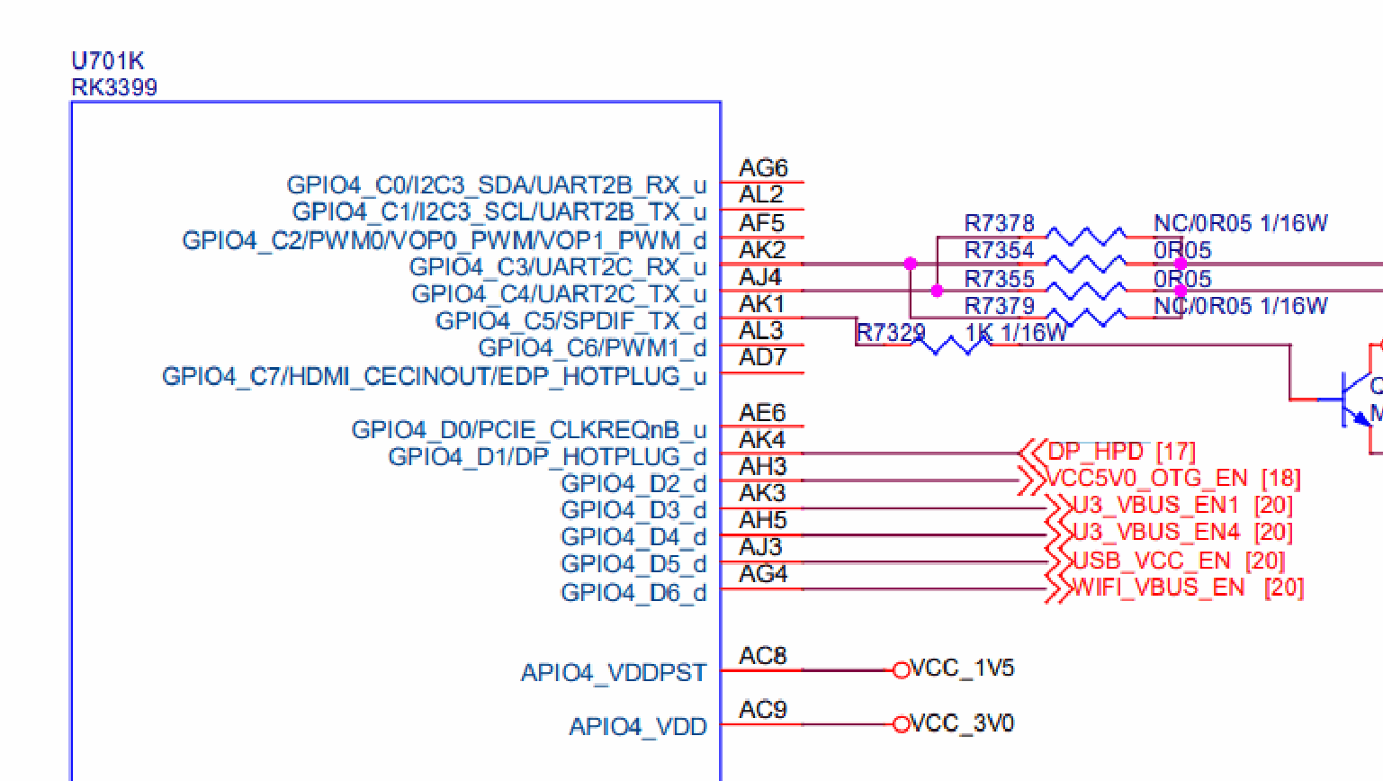
2.2.3.1 Kernel 5.10 and Later Versions
The cdn-dp node configuration is as follows:
&cdn_dp {
   status = "okay";

   pinctrl-names = "default";
   pinctrl-0 = <&dp_hpd>;
   hpd-gpios = <&gpio4 RK_PD1 GPIO_ACTIVE_HIGH>;
   phys = <&tcphy0_dp>;
};
&pinctrl {
   ...

   dp {
      dp_hpd: dp-hpd {
         rockchip,pins = <4 RK_PD1 RK_FUNC_GPIO &pcfg_pull_down>;
      };
   };
   ...
};
PHY node configuration:
&tcphy0 {
   status = "okay";
   rockchip, dp-lane-mux = <2 3 0 1>;

}
If the hardware design is a 2-lane configuration, modify the PHY node configuration as follows:
&tcphy0 {
   status = "okay";
   rockchip, dp-lane-mux = <2 3>;

}
2.2.3.2 Kernel 4.19 and Earlier Versions
The virtual EXTCON driver configuration is as follows:
/ {
   vpd0: virtual-pd0 {
      compatible = "linux,extcon-pd-virtual";

      dp-det-gpios = <&gpio4 RK_PD1 GPIO_ACTIVE_HIGH>;
      /* 0: normal, 1: flip*/
      vpd,init-flip = <0>;
      /* 0: dfp, 1: ufp, 2: dp 3: dp/ufp */
      vpd,init-mode = <2>;
   };
};
In the above configuration:
dp-det-gpios: The HPD GPIO
vpd,init-flip: Used to configure whether the Type-C is in flip mapping. 0 is for normal mapping, and 1 is for flip mapping.
vpd,init-mode: Used to configure the current PHY usage mode. 0 and 1 are for USB only, 2 is for DP only, and 3 is for USB/DP sharing.
DP controller node configuration:
&cdn_dp {
   status = "okay";
   extcon = <&vpd0>;

   phys = <&tcphy0_dp>;
};
If the hardware design is a 2-lane configuration, modify the virtual EXTCON driver configuration as follows:
/ {
   vpd0: virtual-pd0 {

      compatible = "linux,extcon-pd-virtual";
      dp-det-gpios = <&gpio4 RK_PD1 GPIO_ACTIVE_HIGH>;
      /* 0: normal, 1: flip*/
      vpd,init-flip = <0>;
      /* 0: dfp, 1: ufp, 2: dp 3: dp/ufp */
      vpd,init-mode = <3>;
   };
};
2.3 DP Boot Logo
The RK3399 does not support the U-Boot logo at boot.
3. Common DEBUG Methods
3.1 Checking Connector Status
In the /sys/class/drm directory, you can see the various cards registered by the driver. In the following list, card0-DP-1 and card0-DP-2 are DP display devices:
console:/ # ls /sys/class/drm
card0 card0-DP-1 card0-HDMI-A-1 card0-eDP-1 renderD128 version
In the card0-DP-1 directory, the following content is available:
console:/ # ls /sys/class/drm/card0-DP-1/
device dpms edid enabled modes power status subsystem uevent
Check the enable status:
console:/ # cat /sys/class/drm/card0-DP-1/enabled
enabled
Check the connection status:
console:/ # cat /sys/class/drm/card0-DP-1/status
connected
List of supported resolutions for the device:
console:/ # cat /sys/class/drm/card0-DP-1/modes
2560x1440

2048x1280
2048x1152
1920x1200
2048x1080
1920x1080
1920x1080
1920x1080
1920x1080
1920x1080
1920x1080
1600x1200
1680x1050
1280x1024

1280x1024
1280x800
1152x864
1280x720
1280x720
1280x720
1024x768
1024x768
800x600
800x600
720x576
720x576

720x480
720x480
720x480
720x480
640x480
640x480
640x480
640x480
720x400
EDID of the device, which can be saved using the following command:
console:/ # cat /sys/class/drm/card0-DP-1/edid > /data/edid.bin
3.2 Force Enabling/Disabling DP
# Force disable DP
console:/ # echo off > /sys/class/drm/card0-DP-1/status
# Force enable DP

console:/ # echo on > /sys/class/drm/card0-DP-1/status
# Restore hotplug detection
console:/ # echo detect > /sys/class/drm/card0-DP-1/status
3.3 DPCD Read/Write
DPCD is read and written through AUX_CH. The implementation of the read/write node is located at:
/drivers/gpu/drm/drm_dp_aux_dev.c
Before using this feature, make sure the relevant compilation options have been configured:
CONFIG_DRM_DP_AUX_CHARDEV=y
Reading DPCD is as follows:
#if is followed by the aux node. When two DP interfaces are registered, there will be
/dev/drm_dp_aux0 and /dev/drm_dp_aux1.
#skip value is the starting address of the DPCD register.

#count value is the number of DPCD registers to be read.
dd if=/dev/drm_dp_aux0 bs=1 skip=$((0x00200)) count=2 status=none | od -tx1
#The following is the content of two DPCD registers starting at address 0x00200.
console:/ # dd if=/dev/drm_dp_aux1 bs=1 skip=$((0x00200)) count=2 status=none | od -tx1
0000000 01 00
0000002
Writing to DPCD registers:
#echo is followed by the value to be written. The following example writes two hexadecimal
values, 0x0a and 0x80.

#of is followed by the aux node. When two DP interfaces are registered, there will be
/dev/drm_dp_aux0 and /dev/drm_dp_aux1.
#seek is the starting address of the DPCD register.
#count value is the number of DPCD registers to be written.
#The following command writes the values 0x0a and 0x80 to the two DPCD registers starting at
address 0x100.
echo -e -n "\x0a\x80" | dd of=/dev/drm_dp_aux0 bs=1 seek=$((0x100)) count=2 status=none
3.4 Type-C Interface Debugging
Note: This section applies only to Linux Kernel 5.10 and later versions.
The HPD detection part of the Type-C interface is completed by the PD chip, and the software flow of this part is mainly completed by the TCPM framework. The TCPM detection log can be obtained in the following way:
rk3588_s:/ # ls -l /sys/kernel/debug/usb/
total 0
-r--r--r-- 1 root root 0 1970-01-01 00:00 devices

drwxr-xr-x 18 root root 0 1970-01-01 00:00 fc000000.usb
drwxr-xr-x 2 root root 0 1970-01-01 00:00 fc400000.usb
-r--r--r-- 1 root root 0 1970-01-01 00:00 fusb302-2-0022
drwxr-xr-x 4 root root 0 1970-01-01 00:00 ohci
-r--r--r-- 1 root root 0 1970-01-01 00:00 tcpm-2-0022
drwxr-xr-x 2 root root 0 2021-01-01 12:00 usbmon
drwxr-xr-x 2 root root 0 1970-01-01 00:00 uvcvideo
drwxr-xr-x 3 root root 0 1970-01-01 00:00 xhci
In the /sys/kernel/debug/usb/ directory, you can see fusb302-2-0022 and tcpm-2-0022. The fusb302-2-0022 node is for the PD chip, and tcpm-2-0022 is for the TCPM framework node. The command to obtain the TCPM framework log is as follows:
cat /sys/kernel/debug/usb/tcpm-2-0022
Note: In tcpm-2-0022, the middle 2 is the corresponding i2c bus, and the last 0022 is the i2c address of the PD chip.
The command to obtain the PD chip log is as follows:
cat /sys/kernel/debug/usb/fusb302-2-0022
Note: In fusb302-2-0022, the middle 2 is the corresponding i2c bus, and the last 0022 is the i2c address of the PD chip. The above node corresponds to the fusb302 chip, and the node name for different chips will vary.
In addition to the log, other information can be obtained under the Type-C node. The path to the Type-C node is as follows:
console:/ # ls /sys/class/typec
port0 port0-partner
port0 represents the Type-C interface on the SoC side, and port0-partner represents the node directory of the connected device after connecting through the Type-C interface.
Information about the orientation of the Type-C connection:
cat /sys/class/typec/port0/orientation
reverse
Under port0-partner, there may be multiple directories. For the directory corresponding to DP Alt Mode, it will have a displayport subdirectory, and the value of svid will be 0xff01.
ls -l /sys/class/typec/port0-partner/port0-partner.0/
total 0
-r--r--r-- 1 root root 4096 2022-04-14 14:50 active

-r--r--r-- 1 root root 4096 2022-04-14 14:50 description
drwxr-xr-x 2 root root 0 2022-04-14 14:50 displayport
lrwxrwxrwx 1 root root 0 2022-04-14 14:50 driver ->
../../../../../../../../../bus/typec/drivers/typec_displayport
-r--r--r-- 1 root root 4096 2022-04-14 14:50 mode
drwxr-xr-x 2 root root 0 2022-04-14 14:50 mode1
lrwxrwxrwx 1 root root 0 2022-04-14 14:50 port -> ../../port0.0
drwxr-xr-x 2 root root 0 2022-04-14 14:50 power
lrwxrwxrwx 1 root root 0 2022-04-14 14:50 subsystem ->
../../../../../../../../../bus/typec
-r--r--r-- 1 root root 4096 2022-04-14 14:50 svid
-rw-r--r-- 1 root root 4096 2022-04-14 14:50 uevent
-r--r--r-- 1 root root 4096 2022-04-14 14:50 vdo
cat /sys/class/typec/port0-partner/port0-partner.0/svid
ff01
Obtain the current pin assignment information:
cat /sys/class/typec/port0-partner/port0-partner.0/displayport/pin_assignment
C [D]

#The connected device supports C assignment and D assignment. The current configuration is D
assignment.
Note: The above describes the information acquisition of the PD chip based on the TCPM framework. If the PD chip used in combination is not based on the TCPM framework, please confirm the relevant information with the PD chip vendor.
3.5 Checking VOP Status
The command to check the VOP status is as follows:
console:/ # cat /sys/kernel/debug/dri/0/summary
When connecting a DP display to the RK3399, the cat result is as follows:
console:/ # cat /sys/kernel/debug/dri/0/summary
VOP [ff8f0000.vop]: ACTIVE
   Connector: DP-1

      bus_format[0]: Unknown
      overlay_mode[0] output_mode[0] color_space[0]
   Display mode: 2560x1440p60
      clk[241500] real_clk[241500] type[40] flag[9]
      H: 2560 2608 2640 2720
      V: 1440 1443 1448 1481

   win0-0: DISABLED
   win2-0: ACTIVE
      format: AB24 little-endian (0x34324241) SDR[0] color_space[0]
      csc: y2r[0] r2r[0] r2y[0] csc mode[0]
      zpos: 0
      src: pos[0x0] rect[2560x1440]
      dst: pos[0x0] rect[2560x1440]
      buf[0]: addr: 0x00000000f9228000 pitch: 10240 offset: 0
   win2-1: DISABLED
   win2-2: DISABLED
   win2-3: DISABLED
   post: sdr2hdr[0] hdr2sdr[0]

   pre : sdr2hdr[0]
   post CSC: r2y[0] y2r[0] CSC mode[1]
VOP [ff900000.vop]: DISABLED
VOP [ff8f0000.vop]: ACTIVE, where ff8f0000.vop is VOPL, and ACTIVE indicates that the current VOP is enabled.
VOP [ff900000.vop]: DISABLED, where ff900000.vop is VOPB, and DISABLED indicates that the current VOP is disabled.
Connector: DP-1 is the interface information.
Display mode: 2560x1440p60 is the current output resolution information.
winx-x: DISABLED/ACTIVE represents the layer information.
3.6 Adjusting DRM Log Level
DRM has the following print level definitions. You can dynamically enable the corresponding log printing as needed:
enum drm_debug_category {
      DRM_UT_CORE      = 0x01,
      DRM_UT_DRIVER    = 0x02,

      DRM_UT_KMS       = 0x04,
      DRM_UT_PRIME     = 0x08,
      DRM_UT_ATOMIC    = 0x10,
      DRM_UT_VBL       = 0x20,
      DRM_UT_STATE     = 0x40,
      DRM_UT_LEASE     = 0x80,
      DRM_UT_DP        = 0x100,

      DRM_UT_DRMRES    = 0x200,
};
When troubleshooting the DP interface, especially for commit anomalies, the most common approach is to enable ATOMIC, as follows:
echo 0x10 > /sys/module/drm/parameters/debug
If you need to print the DPCD read/write log, enter the following command:
echo 0x100 > /sys/module/drm/parameters/debug
4. PHY Signal Adjustment
The base addresses of UPHY0 and UPHY1 are as follows:
UPHY0 BASE: 0xff7c0000
UPHY1 BASE: 0xff800000
4.1 Voltage Amplitude Register
The voltage amplitude register is TX_TXCC_MGNFS_MULT_000. The register offsets for each lane are as
lane0: 0x10140[7:0]
lane1: 0x10940[7:0]

lane2: 0x11140[7:0]
lane3: 0x11040[7:0]
The adjustment range for the register is 0x00 to 0x36. The larger the register value, the smaller the amplitude; the smaller the register value, the larger the amplitude.
Taking UPHY0 Lane0 as an example, to configure the maximum amplitude:
io -4 0xff7d0140 0x00
To configure the minimum value:
io -4 0xff7d0140 0x36
4.2 Pre-emphasis Register
The pre-emphasis register is TX_TXCC_CPOST_MULT_00. The register offsets for each lane are as follows:
lane0: 0x10130[7:0]
lane1: 0x10930[7:0]
lane2: 0x11130[7:0]

lane3: 0x11930[7:0]
The adjustment range for the register is 0x00 to 0xff. The larger the register value, the greater the pre- emphasis; the smaller the register value, the greater the pre-emphasis.
Taking UPHY0 Lane0 as an example, to configure the maximum pre-emphasis:
io -4 0xff7d0140 0xff
To configure the minimum pre-emphasis:
io -4 0xff7d0140 0x00
4.3 Boost Register
The boost register is TX_DIAG_TX_DRV. The register offsets for each lane are as follows:
lane0: 0x10784[10:8]
lane1: 0x10f84[10:8]
lane2: 0x11784[10:8]

lane3: 0x11f84[10:8]
where bit[10] is the enable bit, and bit[9:8] is the configuration value.
When enabling the boost function, the larger the register value, the greater the boost amplitude; the smaller the register value, the smaller the boost amplitude.
Taking UPHY0 Lane0 as an example, to disable the boost function:
io -4 0xff7d0784 0x000
Taking UPHY0 Lane0 as an example, to enable boost, the configurable values are as follows:
io -4 0xff7d0784 0x400
io -4 0xff7d0784 0x500

io -4 0xff7d0784 0x600
io -4 0xff7d0784 0x700
4.4 Scale Register
The scale register is TX_TXCC_CAL_SCLR_MULT. The register offsets for each lane are as follows:
lane0: 0x1011c[8:0]
lane1: 0x1091c[8:0]
lane2: 0x1111c[8:0]

lane3: 0x1191c[8:0]
where bit[8] is the direction bit, and bit[7:0] is the configuration value.
When bit[8]=1, the larger the register value, the greater the enhancement effect on the voltage amplitude. The configuration range is 0x100 to 0x13c.
Taking UPHY0 Lane0 as an example, to configure the maximum enhancement:
io -4 0xff7d011c 0x13c
To configure the minimum enhancement:
io -4 0xff7d011c 0x100
When bit[8]=0, the larger the register value, the greater the attenuation effect on the voltage amplitude. The configuration range is 0x00 to 0x3c.
Taking UPHY0 Lane0 as an example, to configure the maximum attenuation:
io -4 0xff7d011c 0x3c
To configure the minimum attenuation:
io -4 0xff7d011c 0x00
4.5 Debugging Method
When the default configuration does not meet the requirements, prioritize adjusting the voltage amplitude register and the pre-emphasis register.
When adjusting the voltage amplitude register does not meet the voltage amplitude requirements, then adjust the scale register.
When adjusting the pre-emphasis register does not meet the pre-emphasis requirements, then adjust the boost register.
Note: The RK3399 supports automated signal testing. If there is a testing requirement, please contact FAE for the relevant patch support.
4.6 Code Configuration
The default register configuration is in drivers/phy/rockchip/phy-rockchip-typec.c.
The voltage amplitude register and pre-emphasis register are as follows:
static const struct phy_config tcphy_default_config[3][4] = {
      {{ .swing = 0x2a, .pe = 0x00 },
      { .swing = 0x1f, .pe = 0x15 },

      { .swing = 0x14, .pe = 0x22 },
      { .swing = 0x02, .pe = 0x2b } },

      {{ .swing = 0x21, .pe = 0x00 },
      { .swing = 0x12, .pe = 0x15 },
      { .swing = 0x02, .pe = 0x22 },
      { .swing = 0, .pe = 0 } },

      {{ .swing = 0x15, .pe = 0x00 },
      { .swing = 0x00, .pe = 0x15 },
      { .swing = 0, .pe = 0 },
      { .swing = 0, .pe = 0 } },

};
The rows of the array correspond to swing levels, and the columns correspond to pre-emphasis levels. For example, for swing level = 0 and pre-emphasis level = 1, the corresponding data element is tcphy_default_config[0][1].
The default configuration of the boost register and scale register is in the rockchip_dp_phy_set_voltages function, as follows:
if (dp->voltage[lane] == 2 && dp->pre[lane] == 0 && dp->link_rate != 540000) {
   writel(0x700, tcphy->base + TX_DIAG_TX_DRV(lane));
   writel(0x13c, tcphy->base + TX_TXCC_CAL_SCLR_MULT(lane));

} else {
   writel(0x128, tcphy->base + TX_TXCC_CAL_SCLR_MULT(lane));
   writel(0x0400, tcphy->base + TX_DIAG_TX_DRV(lane));
 }
Note: For RBR, HBR, and HBR2 rates, under swing level = 2 and pre-emphasis level = 0, there are differences in the default configuration of the boost register and scale register.
5. FAQ
5.1 I2C-over-AUX Support
I2C-over-AUX only supports reading EDID and does not support MCCS or other functions.