
本文为 Rockchip RK3399 平台参考,适用原文所述 Linux kernel 4.4 及以上 BSP;TCPM 与 EXTCON 分别按章节注明的内核范围配置。不据此宣称所有 ArmSoM 板卡支持:须核对实际板卡 SoC、DP/Type-C 布线、PD 芯片、固件、设备树和 BSP 补丁。尚未进行 ArmSoM 硬件验证,日志、数值和测试能力均为原文示例或说明。
来源:Rockchip RK3399 Developer Guide DisplayPort,中英文均为 V1.0.0,但封面日期不同。正文保留原文疑点,不将寄存器示例视为可直接执行的板级配置。 校对记录. ArmSoM documentation · Rockchip
1. RK3399 平台 DP 简介
1.1 功能简介
RK3399 DP 接口功能参数如下表格:
| 功能 | RK3399 |
|---|---|
| Version | 1.2 |
| SST | Support |
| MST | Not Support |
| DSC | Not support |
| Max resolution | 4K@60Hz |
| Main-Link lanes | 1/2/4 lanes |
| Main-Link rate | 5.4/2.7/1.62 Gbps/lane |
| AUX_CH | 1 M |
| Color Format | RGB/YUV444/YUV422 |
| Color Depth | 8/10 bit |
| Type-C support | Support |
| I2S | Support |
| SPDIF | Support |
1.2 DP 与 VOP 和 PHY 的连接关系
DP 与 VOP 和 PHY 的连接关系如下:
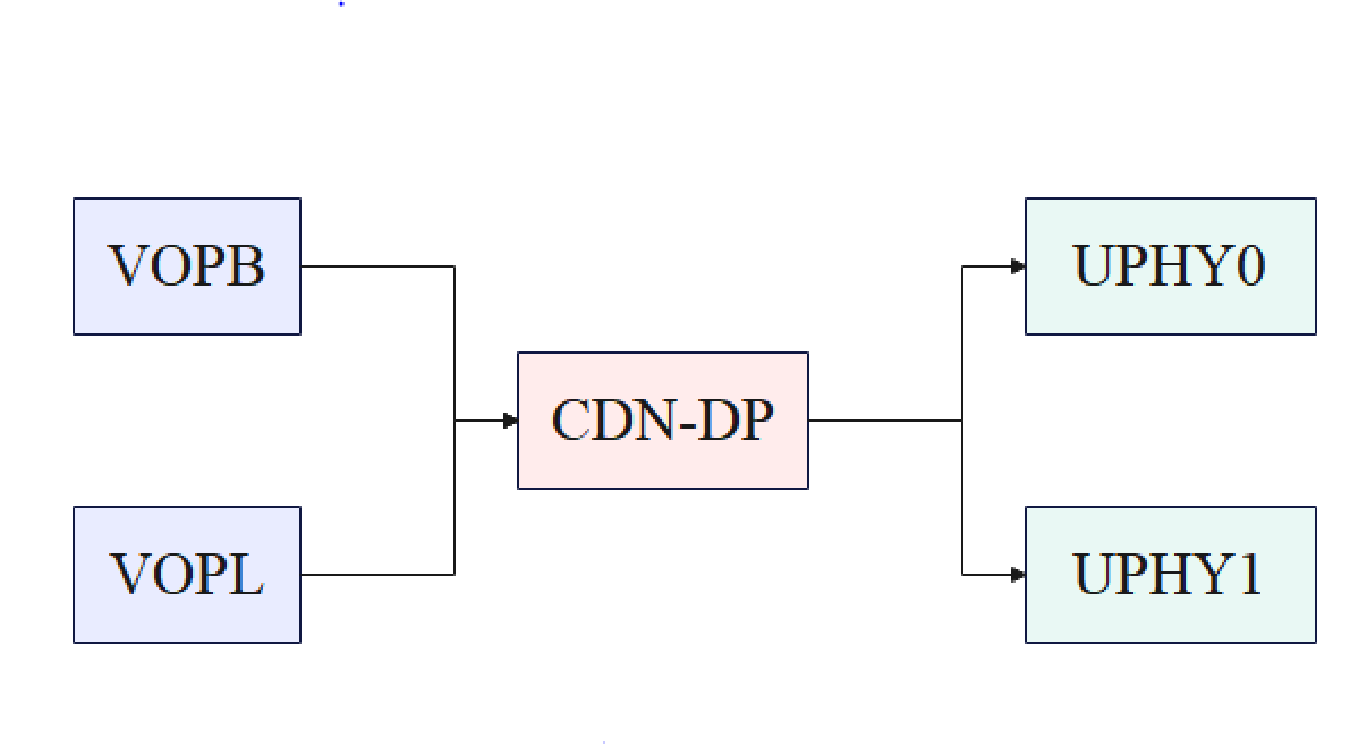
RK3399 上有两个 VOP, 分别是 VOPB 和 VOPL, DP 可以选择其中一个 VOP 作为前级的输入源。当选择VOPB 作为 DP 输入源,DP 支持的最大分辨率为 4096x2160@60Hz, 当选择 VOPL 作为 DP 输入源,DP支持的最大分辨率为 2650x1600@60Hz。DP 后级的输出有两个 UPHY0 和 UPHY1 可以选择,但同一时间只能 UPHY0 或 UPHY1,不能同时使用。
1.3 代码路径
Kernel 驱动代码
# 控制器
drivers/gpu/drm/rockchip/cdn-dp-core.c

drivers/gpu/drm/rockchip/cdn-dp-core.h
drivers/gpu/drm/rockchip/cdn-dp-link-training.c
drivers/gpu/drm/rockchip/cdn-dp-reg.c
drivers/gpu/drm/rockchip/cdn-dp-reg.h
# phy
drivers/phy/rockchip/phy-rockchip-typec.c
参考 DTS 配置
arch/arm64/boot/dts/rockchip/rk3399-evb-ind.dtsi
1.4 驱动加载
RK3399 DP 内部有一个微控制器,DP 开始工作前,会先加载固件,固件存放位置为:
/lib/firmware/rockchip/dptx.bin
通过下面的 log, 判断驱动加载是否完成:
[  3.796582][ T9] rockchip-drm display-subsystem: bound fec00000.dp (ops
cdn_dp_component_ops)
2. 功能配置
DP 和 USB3.0 共用 PHY(Type-C PHY),根据接口的不同有两种配置模式,一种是 DP Alt Mode(Type-C),一种是 Legacy Mode(DP 标准口。
对于这两种方式,目前软件上的流程差异不大。 对于 Type-C 接口, 基于 TCPM 架构的 PD 芯片驱动会通过回调函数把 HPD 信息通知到 PHY 驱动和 DP 控制器驱动,对于 DP 标准口, 通过一个虚拟的 PD 驱动把 HPD Pin 上检测到的 HPD 信息通知到 PHY 驱动和 DP 控制器。
Type-C PHY 上的 Lane 序和 Pin 的对应关系如下:
| PHY Lanes/Module Pins | TypeC Receptacle Pins |
|---|---|
| Lane0 (tx_p/m_ln_0) | TX1+/TX1- (pins A2/A3) |
| Lane1 (tx_rx_p/m_ln_1) | RX1+/RX1- (pins B11/B10) |
| Lane2 (tx_rx_p/m_ln_2) | RX2+/RX2- (pins A11/A10) |
| Lane3 (tx_p/m_ln_3) | TX2+/TX2- (pins B2/B3) |
USB 和 DP lane 在 Type-C PHY 上的映射支持 DP Alt Mode 中所列的 C, D, E 等映射方式(Normal):
| PHY Lanes | C | D | E |
|---|---|---|---|
| 0 | ML2 | SSTX | ML2 |
| 1 | ML3 | SSRX | ML3 |
| 2 | ML0 | ML0 | ML0 |
| 3 | ML1 | ML1 | ML1 |
Flip 的映射如下:
| PHY Lanes | C | D | E |
|---|---|---|---|
| 0 | ML0 | ML0 | ML0 |
| 1 | ML1 | ML1 | ML1 |
| 2 | ML2 | SSTX | ML2 |
| 3 | ML3 | SSRX | ML3 |
另外,Type-C 正反面的极性由 PHY 自身控制。
2.1 DP Alt Mode(Type-C)
以只使用 UPHY0 为例,使能 DP 接口配置如下:
&cdn_dp {
   status = "okay";
   phys = <&tcphy0_dp>;

};
指定 DP 使用的 VOP,如指定 VOPB 如下:
&dp_in_vopb {
   status = "okay";

};

&dp_in_vopl {
   status = "disabled";
};
使能 PHY:
&tcphy0 {
   status = "okay";

};
在 Linux Kernel 5.10 及之后的内核版本,PD 芯片驱动采用 TCPM 架构,注册回调函数通知 HPD 信息。在 Linux Kernel 4.19 及之前的内核版本, PD 芯片采用 EXTCON 机制通知 HPD 信息,这两种不同的机制下 dts 和 PD 芯片相关的部分配置存在差异。
2.1.1 TCPM 架构配置
以只使用 UPHY0 为例,Type-C PHY 需要使能并配置如下内容:
&tcphy0 {
   status = "okay";


   /* DP related config */
   svid = <0xff01>;
   /* DP related config */

   orientation-switch;
   port {
      #address-cells = <1>;
      #size-cells = <0>;
      tcphy0_orientation_switch: endpoint@0 {
         reg = <0>;
         remote-endpoint = <&usbc0_orien_sw>;
      };


      /* DP related config */
      tcphy_dp_altmode_switch: endpoint@1 {
         reg = <1>;
         remote-endpoint = <&dp_mode_sw>;
      };

      /* DP related config */
   };
};
上述配置中:
svid:对 DP 来说是固定值 0xff01。
tcphy_dp_altmode_switch: 用于匹配 PD 芯片的节点。
Type-C 接口需要通过 Type-C 的 CC 检测和 PD 协商来配置 lane 和 HPD 的状态, 所以还需要配置 PD芯片:
usb_con: connector {
   compatible = "usb-c-connector";

   label = "USB-C";
   data-role = "dual";
   power-role = "dual";
   try-power-role = "sink";
   op-sink-microwatt = <1000000>;
   sink-pdos =
      <PDO_FIXED(5000, 2500, PDO_FIXED_USB_COMM)>;
   source-pdos =
      <PDO_FIXED(5000, 1500, PDO_FIXED_USB_COMM)>;

   /* DP related config */
   displayport = <&cdn_dp>;


   altmodes {
      #address-cells = <1>;
      #size-cells = <0>;

      altmode@0 {
         reg = <0>;
         svid = <0xff01>;
         vdo = <0xffffffff>;
      };
   };
   /* DP related config */


   ports {
      #address-cells = <1>;
      #size-cells = <0>;

      port@0 {
         reg = <0>;
         usbc0_orien_sw: endpoint {
           remote-endpoint = <&tcphy0_orientation_switch>;
         };
      };
      /* DP related config */
      port@1 {
         reg = <1>;
         dp_mode_sw: endpoint {
           remote-endpoint = <&tcphy_dp_altmode_switch>;

         };
      };
      /* DP related config */
   };
};
displayport 配置为 DP 节点。
altmode@0 节点中, svid 固定配置为 0xff01, vdo 固定配置为 0xffffffff。
dp_mode_sw 用于匹配 Type-C PHY 节点。
Note: 当前支持的 PD 芯片为 fusb302, hub311。fusb302 对应的驱动为/drivers/usb/typec/tcpm/fusb302.c, hub311 对应的驱动为/drivers/usb/typec/tcpm/tcpci_husb311.c。
2.1.2 EXTCON 机制配置
以只使用 UPHY0 为例,Type-C PHY 需要使能并配置如下内容:
&tcphy0 {
      extcon = <&fusb0>;
      status = "okay";

};
DP 控制器配置如下:
&cdn_dp {
      status = "okay";
      extcon = <&fusb0>;

      phys = <&tcphy0_dp>;
};
上述配置中:
extcon 为引用的 PD 芯片节点。
2.2 Legacy Mode(DP 标准口)
以只使用 UPHY0 为例,使能 DP 接口部分的配置同 Type-C 接口一致,使能 DP 接口配置如下:
&cdn_dp {
   status = "okay";
   phys = <&tcphy0_dp>;

};
指定 DP 使用的 VOP,如指定 VOPB 如下:
&dp_in_vopb {
   status = "okay";
};


&dp_in_vopl {
   status = "disabled";
};
使能 PHY:
&tcphy0 {
   status = "okay";
};
在使用标准接口时,Linux Kernel 5.10 及之后的内核版本,使用 GPIO 中断来获取 HPD 信息。LinuxKernel 4.19 及之前的内核版本, 采用 EXTCON 机制通知 HPD 信息, 需要专⻔的补丁把 HPD 引脚上的信息通过回调函数或 EXTCON 机制进行通知。
2.2.1 DP Lane 映射
在 Typec Phy 接口上,PHY lane 与 Typec 引脚直接的关系如下:
| PHY Lanes/Module Pins | Type-C Receptacle Pins |
|---|---|
| Lane0 (tx_p/m_ln_0) | TX1+/TX1- (pins A2/A3) |
| Lane1 (tx_rx_p/m_ln_1) | RX1+/RX1- (pins B11/B10) |
| Lane2 (tx_rx_p/m_ln_2) | RX2+/RX2- (pins A11/A10) |
| Lane3 (tx_p/m_ln_3) | TX2+/TX2- (pins B2/B3) |
PHY Lanes 只支持固定的两种映射方式,分别是 4 lane 映射和 2 lane 映射。
其中 4 lane 映射如下:
| PHY Lanes | DP lane |
|---|---|
| Lane0 | ML2 |
| Lane1 | ML3 |
| Lane2 | ML0 |
| Lane3 | ML1 |
2 lane 映射如下:
| PHY Lanes | DP lane |
|---|---|
| Lane2 | ML0 |
| Lane3 | ML1 |
2.2.2 HPD 通知补丁
Linux Kernel 4.19 及之前的内核版本, 采用 EXTCON 机制通知 HPD 信息,需要打上如下补丁:
diff --git a/drivers/extcon/Kconfig b/drivers/extcon/Kconfig
index de15bf55895b..90f5c9eb956c 100644
--- a/drivers/extcon/Kconfig

+++ b/drivers/extcon/Kconfig
@@ -158,4 +158,10 @@ config EXTCON_USBC_CROS_EC
       Say Y here to enable USB Type C cable detection extcon support when
       using Chrome OS EC based USB Type-C ports.
@@ -158,4 +158,10 @@ config EXTCON_USBC_CROS_EC
       Say Y here to enable USB Type C cable detection extcon support when
       using Chrome OS EC based USB Type-C ports.

+config EXTCON_PD_VIRTUAL
+     tristate "Rockchip Virtual PD EXTCON support"
+     depends on GPIOLIB
+     help
+      Say Y here to enable Rockchip Virtual PD extcon support.

+
 endif
diff --git a/drivers/extcon/Makefile b/drivers/extcon/Makefile
index 0888fdeded72..d8dd2b8647c9 100644
--- a/drivers/extcon/Makefile
+++ b/drivers/extcon/Makefile
@@ -22,3 +22,4 @@ obj-$(CONFIG_EXTCON_RT8973A) += extcon-rt8973a.o
 obj-$(CONFIG_EXTCON_SM5502) += extcon-sm5502.o
 obj-$(CONFIG_EXTCON_USB_GPIO) += extcon-usb-gpio.o
 obj-$(CONFIG_EXTCON_USBC_CROS_EC) += extcon-usbc-cros-ec.o
+obj-$(CONFIG_EXTCON_PD_VIRTUAL) += extcon-pd-virtual.o
diff --git a/drivers/extcon/extcon-pd-virtual.c b/drivers/extcon/extcon-pd-

virtual.c
new file mode 100755
index 000000000000..94095beff9ff
--- /dev/null
+++ b/drivers/extcon/extcon-pd-virtual.c
@@ -0,0 +1,578 @@
+/*
+ * Copyright (c) 2024, Fuzhou Rockchip Electronics Co., Ltd
+ *
+ * This program is free software; you can redistribute it and/or modify it
+ * under the terms and conditions of the GNU General Public License,
+ * version 2, as published by the Free Software Foundation.
+ */

+
+#include <linux/init.h>
+#include <linux/kernel.h>
+#include <linux/module.h>
+#include <linux/platform_device.h>
+#include <linux/slab.h>
+#include <linux/extcon-provider.h>
+#include <linux/gpio.h>
+#include <linux/of_gpio.h>
+#include <linux/irq.h>
+#include <linux/interrupt.h>
+#include <linux/delay.h>

+
+struct virtual_pd {
+     struct extcon_dev *extcon;
+     struct gpio_desc *gpio_vbus_5v;
+     struct gpio_desc *gpio_hdmi_5v;
+     struct gpio_desc *gpio_irq;
+     struct device *dev;
+     bool flip;
+     bool usb_ss;
+     bool enable;
+     u8 mode;
+     int irq;

+     int enable_irq;
+     int plug_state;
+     struct work_struct work;
+     struct workqueue_struct *virtual_pd_wq;
+     spinlock_t irq_lock;
+     struct delayed_work irq_work;
+     int shake_lev;
+};
+
+static const unsigned int vpd_cable[] = {
+     EXTCON_USB,
+     EXTCON_USB_HOST,
+     EXTCON_USB_VBUS_EN,

+     EXTCON_CHG_USB_SDP,
+     EXTCON_CHG_USB_CDP,
+     EXTCON_CHG_USB_DCP,
+/*
+ FIXME: There's no real pd phy, control the charging is very
+ dangerous, just rely on the BC detection. We don't use slow
+ and fast.
+*/
+     EXTCON_CHG_USB_SLOW,
+     EXTCON_CHG_USB_FAST,
+     EXTCON_DISP_DP,
+     EXTCON_NONE,

+};
+
+enum vpd_mode {
+     VPD_DFP = 0,
+     VPD_UFP,
+     VPD_DP,
+     VPD_DP_UFP,
+};
+
+static void vpd_set_vbus_enable(struct virtual_pd *vpd, bool enable)
+{
+     extcon_set_state(vpd->extcon, EXTCON_USB_VBUS_EN, enable);
+     extcon_sync(vpd->extcon, EXTCON_USB_VBUS_EN);

+     if (vpd->gpio_vbus_5v)
+           gpiod_set_raw_value(vpd->gpio_vbus_5v, enable);
+}
+
+static void vpd_extcon_notify(struct virtual_pd *vpd, bool flip, bool usb_ss,
+                     bool dfp, bool ufp, bool dp)

+{
+     union extcon_property_value property;
+
+     property.intval = flip;
+     extcon_set_property(vpd->extcon, EXTCON_USB,
+                    EXTCON_PROP_USB_TYPEC_POLARITY, property);
+     extcon_set_property(vpd->extcon, EXTCON_USB_HOST,
+                    EXTCON_PROP_USB_TYPEC_POLARITY, property);
+     extcon_set_property(vpd->extcon, EXTCON_DISP_DP,
+                    EXTCON_PROP_USB_TYPEC_POLARITY, property);
+
+     property.intval = usb_ss;

+     extcon_set_property(vpd->extcon, EXTCON_USB,
+                    EXTCON_PROP_USB_SS, property);
+     extcon_set_property(vpd->extcon, EXTCON_USB_HOST,
+                    EXTCON_PROP_USB_SS, property);
+     extcon_set_property(vpd->extcon, EXTCON_DISP_DP,
+                    EXTCON_PROP_USB_SS, property);
+     extcon_set_state(vpd->extcon, EXTCON_USB, ufp);
+     extcon_set_state(vpd->extcon, EXTCON_USB_HOST, dfp);
+     extcon_set_state(vpd->extcon, EXTCON_DISP_DP, dp);
+     extcon_sync(vpd->extcon, EXTCON_USB);
+     extcon_sync(vpd->extcon, EXTCON_USB_HOST);
+     extcon_sync(vpd->extcon, EXTCON_DISP_DP);
+}

+
+static void vpd_extcon_notify_set(struct virtual_pd *vpd)
+{
+     bool flip = vpd->flip, usb_ss = vpd->usb_ss;
+     bool dfp = 0, ufp = 0, dp = 0;
+
+     switch (vpd->mode) {
+     case VPD_DFP:
+           dfp = 1;
+           break;
+     case VPD_DP:
+           dp = 1;

+           dfp = 1;
+           break;
+     case VPD_DP_UFP:
+           dp = 1;
+           ufp = 1;
+           break;
+     case VPD_UFP:
+           /* fall through */
+     default:
+           ufp = 1;
+           break;
+     }
+

+     vpd_set_vbus_enable(vpd, !ufp);
+     vpd_extcon_notify(vpd, flip, usb_ss, dfp, ufp, dp);
+}
+
+static void vpd_extcon_notify_clr(struct virtual_pd *vpd)
+{

+     vpd_set_vbus_enable(vpd, 0);
+     vpd_extcon_notify(vpd, vpd->flip, vpd->usb_ss, 0, 0, 0);
+}
+
+static ssize_t vpd_flip_show(struct device *dev,
+                    struct device_attribute *attr, char *buf)
+{
+     struct virtual_pd *vpd = dev_get_drvdata(dev);
+
+     return sprintf(buf, "%d\n", vpd->flip);
+}
+

+static ssize_t vpd_flip_store(struct device *dev,
+                     struct device_attribute *attr,
+                     const char *buf, size_t count)
+{
+     struct virtual_pd *vpd = dev_get_drvdata(dev);
+
+     if (vpd->enable)
+           goto out;
+
+     if (strncmp(buf, "1", 1) == 0)
+           vpd->flip = true;
+     else
+           vpd->flip = false;

+out:
+     return count;
+}
+static DEVICE_ATTR(flip, S_IWUSR | S_IRUSR, vpd_flip_show, vpd_flip_store);
+
+static ssize_t vpd_ss_show(struct device *dev,
+                   struct device_attribute *attr, char *buf)
+{
+     struct virtual_pd *vpd = dev_get_drvdata(dev);
+
+     return sprintf(buf, "%d\n", vpd->usb_ss);
+}

+
+static ssize_t vpd_ss_store(struct device *dev,
+                     struct device_attribute *attr,
+                     const char *buf, size_t count)
+{
+     struct virtual_pd *vpd = dev_get_drvdata(dev);
+
+     if (vpd->enable)
+           goto out;
+
+     if (strncmp(buf, "1", 1) == 0)
+           vpd->usb_ss = true;
+     else

+           vpd->usb_ss = false;
+out:
+     return count;
+}
+static DEVICE_ATTR(ss, S_IWUSR | S_IRUSR, vpd_ss_show, vpd_ss_store);
+

+static ssize_t vpd_mode_show(struct device *dev,
+                   struct device_attribute *attr, char *buf)
+{
+     struct virtual_pd *vpd = dev_get_drvdata(dev);
+
+     return sprintf(buf, "%d\n", vpd->mode);
+}
+
+static ssize_t vpd_mode_store(struct device *dev,
+                     struct device_attribute *attr,
+                     const char *buf, size_t count)
+{

+     struct virtual_pd *vpd = dev_get_drvdata(dev);
+
+     if (vpd->enable)
+           goto out;
+
+     if (strncmp(buf, "0", 1) == 0)
+           vpd->mode = VPD_DFP;
+     else if (strncmp(buf, "2", 1) == 0)
+           vpd->mode = VPD_DP;
+     else if (strncmp(buf, "3", 1) == 0)
+           vpd->mode = VPD_DP_UFP;
+     else
+           vpd->mode = VPD_UFP;

+out:
+     return count;
+}
+static DEVICE_ATTR(mode, S_IWUSR | S_IRUSR, vpd_mode_show, vpd_mode_store);
+
+static ssize_t vpd_enable_show(struct device *dev,
+                    struct device_attribute *attr, char *buf)
+{
+     struct virtual_pd *vpd = dev_get_drvdata(dev);
+
+     return sprintf(buf, "%d\n", vpd->enable);
+}

+
+static ssize_t vpd_enable_store(struct device *dev,
+                     struct device_attribute *attr,
+                     const char *buf, size_t count)
+{
+     struct virtual_pd *vpd = dev_get_drvdata(dev);
+
+     if (strncmp(buf, "1", 1) == 0) {
+           if (vpd->enable)
+                 goto out;
+           vpd->enable = true;
+           vpd_extcon_notify_set(vpd);
+     } else {

+           if (!vpd->enable)
+                 goto out;
+           vpd->enable = false;
+           vpd_extcon_notify_clr(vpd);
+     }
+out:

+     return count;
+}
+static DEVICE_ATTR(enable, S_IWUSR | S_IRUSR, vpd_enable_show,
vpd_enable_store);
+
+static struct attribute *vpd_attributes[] = {
+     &dev_attr_flip.attr,
+     &dev_attr_ss.attr,
+     &dev_attr_mode.attr,
+     &dev_attr_enable.attr,
+     NULL
+};

+
+static const struct attribute_group vpd_attr_group = {
+     .attrs = vpd_attributes,
+};
+
+void vpd_irq_disable(struct virtual_pd *vpd)
+{
+     unsigned long irqflags = 0;
+
+     spin_lock_irqsave(&vpd->irq_lock, irqflags);
+     if (!vpd->enable_irq) {
+           disable_irq_nosync(vpd->irq);
+           vpd->enable_irq = 1;

+     } else {
+           dev_warn(vpd->dev, "irq have already disabled\n");
+     }
+     spin_unlock_irqrestore(&vpd->irq_lock, irqflags);
+}
+
+void vpd_irq_enable(struct virtual_pd *vpd)
+{
+     unsigned long irqflags = 0;
+
+     spin_lock_irqsave(&vpd->irq_lock, irqflags);
+     if (vpd->enable_irq) {

+           enable_irq(vpd->irq);
+           vpd->enable_irq = 0;
+     }
+     spin_unlock_irqrestore(&vpd->irq_lock, irqflags);
+}
+
+static void virtual_pd_work_func(struct work_struct *work)
+{
+     struct virtual_pd *vpd;
+
+     vpd = container_of(work, struct virtual_pd, work);
+     dev_info(vpd->dev, "%s %d =====>\n",__FUNCTION__,__LINE__);
+}

+
+static void extcon_pd_delay_irq_work(struct work_struct *work)
+{
+     struct virtual_pd *vpd =
+           container_of(work, struct virtual_pd, irq_work.work);
+     int lev;

+
+     lev = gpiod_get_raw_value(vpd->gpio_irq);
+
+     if(vpd->shake_lev != lev) {
+           vpd_irq_enable(vpd);
+           return;
+     }
+
+     switch(vpd->plug_state) {
+           case 1:
+                 if(lev==0) {
+                       vpd->enable = false;

+                       vpd_extcon_notify_clr(vpd);
+                       vpd->plug_state=0;
+                 }
+                 break;
+           case 0:
+                 if(lev==1) {
+                       vpd->enable = true;
+                       vpd_extcon_notify_set(vpd);
+                       vpd->plug_state=1;
+                 }
+                 break;
+           default:
+                 break;

+     }
+     vpd_irq_enable(vpd);
+}
+
+static irqreturn_t dp_det_irq_handler(int irq, void *dev_id)
+{
+     struct virtual_pd *vpd = dev_id;
+     int lev;
+
+     lev=gpiod_get_raw_value(vpd->gpio_irq);
+     vpd->shake_lev = lev;
+     schedule_delayed_work(&vpd->irq_work, msecs_to_jiffies(10));

+     vpd_irq_disable(vpd);
+     return IRQ_HANDLED;
+}
+
+static void vpd_extcon_init(struct virtual_pd *vpd)
+{
+     struct device *dev = vpd->dev;
+     u32 tmp = 0;
+     int ret = 0;
+
+     ret = device_property_read_u32(dev, "vpd,init-flip", &tmp);
+     if (ret < 0)
+           vpd->flip = 0;

+     else
+           vpd->flip = tmp;
+     dev_dbg(dev, "init-flip = %d\n", vpd->flip);
+
+     ret = device_property_read_u32(dev, "vpd,init-ss", &tmp);
+     if (ret < 0)

+           vpd->usb_ss = 0;
+     else
+           vpd->usb_ss = tmp;
+     dev_dbg(dev, "init-ss = %d\n", vpd->usb_ss);
+
+     ret = device_property_read_u32(dev, "vpd,init-mode", &tmp);
+     if (ret < 0)
+           vpd->mode = 0;
+     else
+           vpd->mode = tmp;
+     dev_dbg(dev, "init-mode = %d\n", vpd->flip);
+     if(gpiod_get_raw_value(vpd->gpio_irq)) {

+           vpd_extcon_notify_set(vpd);
+           vpd->plug_state=1;
+     }
+}
+
+static int vpd_extcon_probe(struct platform_device *pdev)
+{
+     struct virtual_pd *vpd;
+     struct device *dev = &pdev->dev;
+     int ret = 0;
+
+     dev_info(dev, "%s: %d start\n", __func__, __LINE__);
+

+     vpd = devm_kzalloc(dev, sizeof(*vpd), GFP_KERNEL);
+     if (!vpd)
+           return -ENOMEM;
+
+     vpd->dev = dev;
+     dev_set_drvdata(dev, vpd);
+     vpd->enable = 1;
+
+     vpd->extcon = devm_extcon_dev_allocate(dev, vpd_cable);
+     if (IS_ERR(vpd->extcon)) {
+           dev_err(dev, "allocat extcon failed\n");
+           return PTR_ERR(vpd->extcon);

+     }
+
+     ret = devm_extcon_dev_register(dev, vpd->extcon);
+     if (ret) {
+           dev_err(dev, "register extcon failed: %d\n", ret);
+           return ret;
+     }
+
+     vpd->gpio_vbus_5v = devm_gpiod_get_optional(dev,"vbus-5v",
+                                     GPIOD_OUT_LOW);
+     if (IS_ERR(vpd->gpio_vbus_5v)) {
+           dev_warn(dev, "maybe miss named GPIO for vbus-5v\n");
+           vpd->gpio_vbus_5v = NULL;

+     } else
+           gpiod_set_raw_value(vpd->gpio_vbus_5v, 0);
+
+     vpd->gpio_hdmi_5v = devm_gpiod_get_optional(dev,"hdmi-5v",
+                                     GPIOD_OUT_LOW);
+     if (IS_ERR(vpd->gpio_hdmi_5v)) {

+           dev_warn(dev, "maybe miss named GPIO for gpio_hdmi_5v\n");
+           vpd->gpio_hdmi_5v = NULL;
+     }
+
+     vpd->gpio_irq = devm_gpiod_get_optional(dev,"dp-det",
+                                     GPIOD_OUT_LOW);
+     if (IS_ERR(vpd->gpio_irq)) {
+           dev_warn(dev, "maybe miss named GPIO for dp-det\n");
+           vpd->gpio_irq = NULL;
+     }
+
+     ret = extcon_set_property_capability(vpd->extcon, EXTCON_USB,

+                                EXTCON_PROP_USB_TYPEC_POLARITY);
+     if (ret) {
+           dev_err(dev,
+                 "set USB property capability failed: %d\n", ret);
+           return ret;
+     }
+
+     ret = extcon_set_property_capability(vpd->extcon, EXTCON_USB_HOST,
+                                EXTCON_PROP_USB_TYPEC_POLARITY);
+     if (ret) {
+           dev_err(dev,
+                 "set USB_HOST property capability failed: %d\n",
+                 ret);

+           return ret;
+     }
+
+     ret = extcon_set_property_capability(vpd->extcon, EXTCON_DISP_DP,
+                                EXTCON_PROP_USB_TYPEC_POLARITY);
+     if (ret) {
+           dev_err(dev,
+                 "set DISP_DP property capability failed: %d\n",
+                 ret);
+           return ret;
+     }
+

+     ret = extcon_set_property_capability(vpd->extcon, EXTCON_USB,
+                                EXTCON_PROP_USB_SS);
+     if (ret) {
+           dev_err(dev,
+                 "set USB USB_SS property capability failed: %d\n",
+                 ret);
+           return ret;
+     }
+
+     ret = extcon_set_property_capability(vpd->extcon, EXTCON_USB_HOST,
+                                EXTCON_PROP_USB_SS);
+     if (ret) {
+           dev_err(dev,

+                 "set USB_HOST USB_SS property capability failed: %d\n",
+                 ret);
+           return ret;
+     }
+
+     ret = extcon_set_property_capability(vpd->extcon, EXTCON_DISP_DP,

+                                EXTCON_PROP_USB_SS);
+     if (ret) {
+           dev_err(dev,
+                 "set DISP_DP USB_SS property capability failed: %d\n",
+                 ret);
+           return ret;
+     }
+
+     ret = extcon_set_property_capability(vpd->extcon, EXTCON_CHG_USB_FAST,
+                                EXTCON_PROP_USB_TYPEC_POLARITY);
+     if (ret) {
+           dev_err(dev,

+                 "set USB_PD property capability failed: %d\n", ret);
+           return ret;
+     }
+
+     vpd_extcon_init(vpd);
+     INIT_DELAYED_WORK(&vpd->irq_work, extcon_pd_delay_irq_work);
+
+     vpd->irq=gpiod_to_irq(vpd->gpio_irq);
+     dev_info(dev, "%s %d =====>%d\n",__FUNCTION__,__LINE__,vpd->irq);
+     if (vpd->irq){
+           ret = devm_request_threaded_irq(dev,
+                                  vpd->irq,
+                                  NULL,

+                                  dp_det_irq_handler,
+                                  //IRQF_TRIGGER_HIGH |
IRQF_ONESHOT,
+                                  IRQF_TRIGGER_FALLING |
IRQF_TRIGGER_RISING |
+                                  IRQF_ONESHOT,
+                                  NULL,
+                                  vpd);
+     } else {
+           dev_err(dev,"gpio can not be irq !\n");
+     }
+

+     vpd->virtual_pd_wq = create_workqueue("virtual_pd_wq");
+     INIT_WORK(&vpd->work, virtual_pd_work_func);
+     ret = sysfs_create_group(&dev->kobj, &vpd_attr_group);
+     if (ret < 0)
+           dev_warn(dev, "attr group create failed\n");
+
+     dev_info(dev, "%s: %d sussess\n", __func__, __LINE__);
+
+     return 0;
+}
+
+static int vpd_extcon_remove(struct platform_device *pdev)
+{

+     return 0;
+}
+
+#ifdef CONFIG_PM_SLEEP
+static int vpd_extcon_suspend(struct device *dev)
+{

+     struct virtual_pd *vpd = dev_get_drvdata(dev);
+
+     int lev=0;
+     lev = gpiod_get_raw_value(vpd->gpio_irq);
+     cancel_delayed_work_sync(&vpd->irq_work);
+     vpd_irq_disable(vpd);
+     if (vpd->gpio_hdmi_5v)
+           gpiod_set_raw_value(vpd->gpio_hdmi_5v, 0);
+     return 0;
+}
+
+static int vpd_extcon_resume(struct device *dev)

+{
+     struct virtual_pd *vpd = dev_get_drvdata(dev);
+     if (vpd->gpio_hdmi_5v) {
+           gpiod_set_raw_value(vpd->gpio_hdmi_5v, 1);
+           msleep(800);
+     }
+     vpd_irq_enable(vpd);
+     return 0;
+}
+#endif
+
+static SIMPLE_DEV_PM_OPS(vpd_extcon_pm_ops,
+                 vpd_extcon_suspend, vpd_extcon_resume);

+
+static const struct of_device_id vpd_extcon_dt_match[] = {
+     { .compatible = "linux,extcon-pd-virtual", },
+     { /* sentinel */ }
+};
+MODULE_DEVICE_TABLE(of, usb_extcon_dt_match);
+
+static struct platform_driver vpd_extcon_driver = {
+     .probe      = vpd_extcon_probe,
+     .remove     = vpd_extcon_remove,
+     .driver     = {
+           .name = "extcon-pd-virtual",

+           .pm   = &vpd_extcon_pm_ops,
+           .of_match_table = vpd_extcon_dt_match,
+     },
+};
+
+static int __init __vpd_extcon_init(void)
+{
+           return platform_driver_register(&vpd_extcon_driver);
+}
+
+static void __exit __vpd_extcon_exit(void)
+{
+           platform_driver_unregister(&vpd_extcon_driver);

+}
+
+module_init(__vpd_extcon_init);
+module_exit(__vpd_extcon_exit);
+
+MODULE_LICENSE("GPL");

+MODULE_AUTHOR("rockchip");
+MODULE_DESCRIPTION("Virtual Typec-pd extcon driver");
除上述补丁外,需要使能如下的编译选项:
CONFIG_EXTCON_PD_VIRTUAL=y
2.2.3 DTS 配置
以只使用 UPHY0 为例,如若硬件设计如下,DP lane 映射如下图:
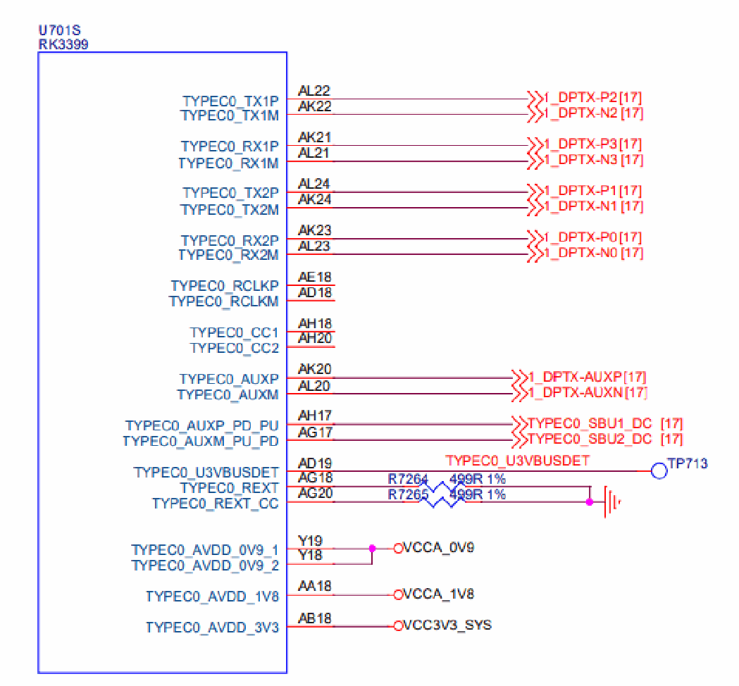
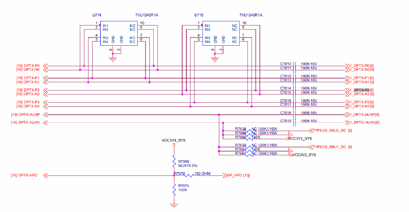
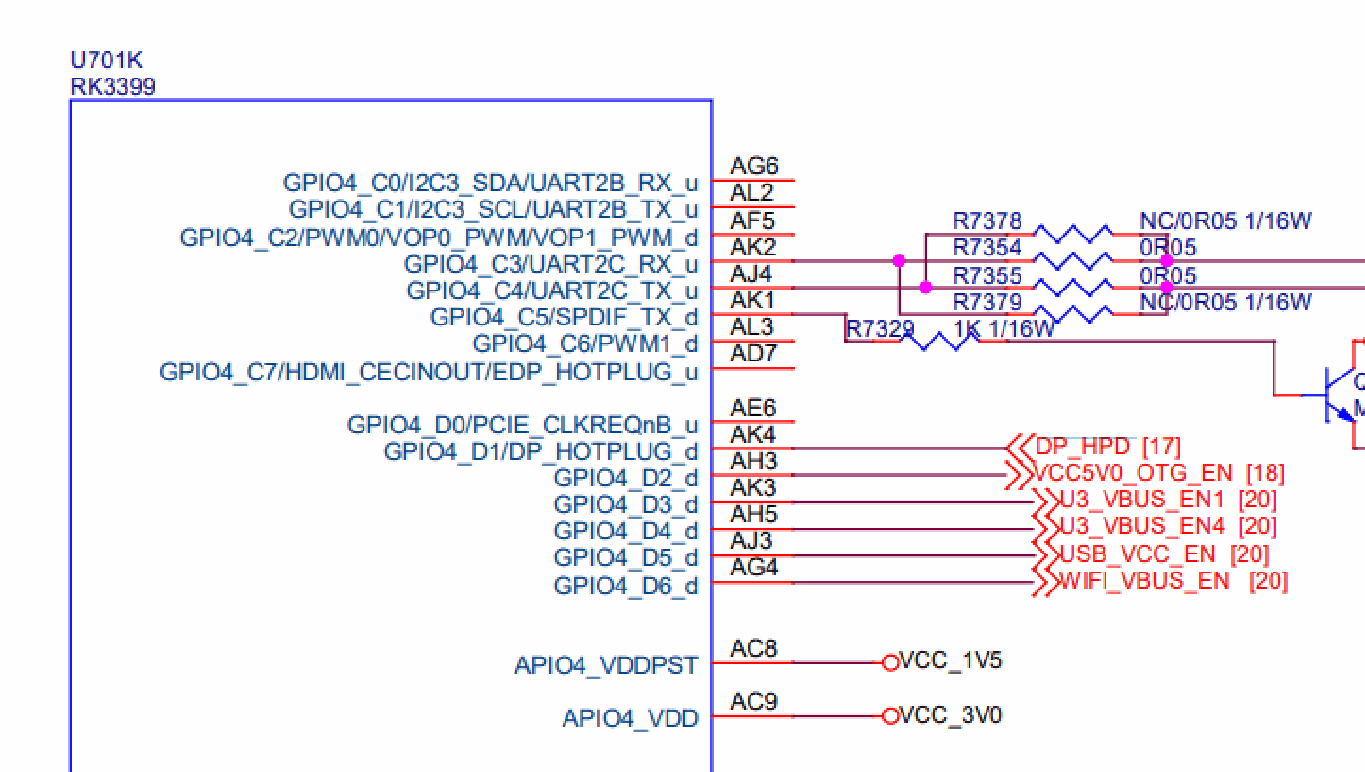
2.2.3.1 Kernel 5.10 及以上版本
cdn-dp 节点配置如下:
虚拟 PD 驱动配置 dts 如下:
&cdn_dp {
   status = "okay";
   pinctrl-names = "default";

   pinctrl-0 = <&dp_hpd>;
   hpd-gpios = <&gpio4 RK_PD1 GPIO_ACTIVE_HIGH>;
   phys = <&tcphy0_dp>;
};

&pinctrl {
   ...
   dp {
      dp_hpd: dp-hpd {
         rockchip,pins = <4 RK_PD1 RK_FUNC_GPIO &pcfg_pull_down>;
      };
   };

   ...
};
phy 节点配置如下:
&tcphy0 {
   status = "okay";
   rockchip, dp-lane-mux = <2 3 0 1>;

}
如果硬件设计为 2 lane 的配置,修改 phy 节点配置如下:
&tcphy0 {
   status = "okay";
   rockchip, dp-lane-mux = <2 3>;

}
2.2.3.2 Kernel 4.19 及以下版本
虚拟的 EXTCON 驱动配置如下:
/ {
   vpd0: virtual-pd0 {
      compatible = "linux,extcon-pd-virtual";

      dp-det-gpios = <&gpio4 RK_PD1 GPIO_ACTIVE_HIGH>;
      /* 0: normal, 1: flip*/
      vpd,init-flip = <0>;
      /* 0: dfp, 1: ufp, 2: dp 3: dp/ufp */
      vpd,init-mode = <2>;
   };
};
上述配置中:
dp-det-gpios: 为 hpd gpio
vpd,init-flip: 用于配置 Type-C 是否为 flip 的 mapping, 0 为 normal 的mapping, 1 为 flipmapping
vpd,init-mode: 用于配置当前 PHY 的使用模式, 0, 1 为 USB only, 2 为 DP only, 3 为 USB/DP 共用
DP 控制器节点配置如下:
&cdn_dp {
   status = "okay";

   extcon = <&vpd0>;
   phys = <&tcphy0_dp>;
};
如果硬件设计为 2 lane 的配置,修改虚拟的 EXTCON 驱动配置如下:
/ {
   vpd0: virtual-pd0 {
      compatible = "linux,extcon-pd-virtual";

      dp-det-gpios = <&gpio4 RK_PD1 GPIO_ACTIVE_HIGH>;
      /* 0: normal, 1: flip*/
      vpd,init-flip = <0>;
      /* 0: dfp, 1: ufp, 2: dp 3: dp/ufp */
      vpd,init-mode = <3>;
   };
};
2.3 DP 开机 logo
RK3399 不支持开机 U-Boot logo。
3. 常用 DEBUG 方法
3.1 查看 connector 状态
在 /sys/class/drm 目录下可以看到驱动注册的各个 card,在如下显示的内容汇总,card0-DP-1 和card0-DP-2 是 DP 显示设备
console:/ # ls /sys/class/drm
card0 card0-DP-1 card0-HDMI-A-1 card0-eDP-1 renderD128 version
在 card0-DP-1 目录下有如下内容:
console:/ # ls /sys/class/drm/card0-DP-1/
device dpms edid enabled modes power status subsystem uevent
enable 查看使能状态:
console:/ # cat /sys/class/drm/card0-DP-1/enabled
enabled
status 查看连接状态:
console:/ # cat /sys/class/drm/card0-DP-1/status
connected
modes 设备支持的分辨率列表:
console:/ # cat /sys/class/drm/card0-DP-1/modes
2560x1440
2048x1280

2048x1152
1920x1200
2048x1080
1920x1080
1920x1080
1920x1080
1920x1080
1920x1080
1920x1080
1600x1200
1680x1050
1280x1024

1280x1024
1280x800
1152x864
1280x720

1280x720
1280x720
1024x768
1024x768
800x600
800x600
720x576
720x576
720x480
720x480
720x480
720x480

640x480
640x480
640x480
640x480
720x400
edid 设备的 EDID, 通过如下命令保存:
console:/ # cat /sys/class/drm/card0-DP-1/edid > /data/edid.bin
3.2 强制使能/禁用 DP
#强制禁⽤ DP
console:/ # echo off > /sys/class/drm/card0-DP-1/status
#强制使能 DP

console:/ # echo on > /sys/class/drm/card0-DP-1/status
#恢复热插拔检测
console:/ # echo detect > /sys/class/drm/card0-DP-1/status
3.3 DPCD 读写
DPCD 通过 AUX_CH 读写,读写节点的实现在
/drivers/gpu/drm/drm_dp_aux_dev.c
使用此功能前,先确认相关的编译选项是否已经配置:
CONFIG_DRM_DP_AUX_CHARDEV=y
读取 DPCD 如下:
#if 后⾯为 aux 节点,当注册两个 DP 接⼝时,会有 /dev/drm_dp_aux0 和 /dev/drm_dp_aux1
#skip 值为起始的 DPCD 寄存器地址
#count 值为要读取的 DPCD 寄存器的数量

dd if=/dev/drm_dp_aux0 bs=1 skip=$((0x00200)) count=2 status=none | od -tx1
#如下为读取地址为  0x00200 开始的 2 个 DPCD 寄存器的内容
console:/ # dd if=/dev/drm_dp_aux1 bs=1 skip=$((0x00200)) count=2 status=none |
od -tx1
0000000 01 00
0000002
写入 DPCD 寄存器:
#echo 后为要写⼊的值, 如下为需要写⼊两个  16 进制的值,分别为 0x0a, 0x80
#of 后⾯为 aux 节点,当注册两个 DP 接⼝时,会有 /dev/drm_dp_aux0 和 /dev/drm_dp_aux1

#seek 后为起始的 DPCD 寄存器地址
#count 值为要写⼊的 DPCD 寄存器的数量
#如下指令为把  0x0a 和 0x80 两个值写⼊ 0x100 起始的两个 DPCD 寄存器处
echo -e -n "\x0a\x80" | dd of=/dev/drm_dp_aux0 bs=1 seek=$((0x100)) count=2
status=none
3.4 Type-C 接口 Debug
Note: 此章节内容仅使用 Linux Kernel 5.10 及以上版本。
Type-C 接口的 HPD 检测部分由 PD 芯片完成,这部分的软件流程主要由 TCPM 的框架完成,TCPM 检测这部分 log 可以由以下方式获取:
rk3588_s:/ # ls -l /sys/kernel/debug/usb/
total 0
-r--r--r-- 1 root root 0 1970-01-01 00:00 devices

drwxr-xr-x 18 root root 0 1970-01-01 00:00 fc000000.usb
drwxr-xr-x 2 root root 0 1970-01-01 00:00 fc400000.usb
-r--r--r-- 1 root root 0 1970-01-01 00:00 fusb302-2-0022
drwxr-xr-x 4 root root 0 1970-01-01 00:00 ohci
-r--r--r-- 1 root root 0 1970-01-01 00:00 tcpm-2-0022
drwxr-xr-x 2 root root 0 1970-01-01 00:00 usbmon
drwxr-xr-x 2 root root 0 2021-01-01 12:00 uvcvideo
drwxr-xr-x 3 root root 0 1970-01-01 00:00 xhci
在 /sys/kernel/debug/usb/ 目录中,可以看到 fusb302-2-0022 和 tcpm-2-0022, 其中 fusb302-2-0022 为 PD 芯片的节点, tcpm-2-0022 为 TCPM 框架的节点, 获取 TCPM 框架的 log 命令如下:
cat /sys/kernel/debug/usb/tcpm-2-0022
Note: tcpm-2-0022, 中间的 2 为 对应的 i2c 总线,最后的 0022 为 PD 芯片对应的 i2c 地址
获取 PD 芯片的 log 如下:
cat /sys/kernel/debug/usb/fusb302-2-0022
Note: fusb302-2-0022, 中间的 2 为 对应的 i2c 总线,最后的 0022 为 PD 芯片对应的 i2c 地址, 上述节点对应 fusb302 芯片,不同芯片节点名称不一样。
除了 log 外,在 Type-C 节点下还可以获取其他的一些信息,Type-C 节点路径如下:
console:/ # ls /sys/class/typec
port0 port0-partner
port0 表示 SoC 这端的 Type-C 接口, port0-partner 表示通过 Type-C 连接设备后设备端的节点目录。
Type-C 连接的正反面信息:
cat /sys/class/typec/port0/orientation
reverse
port0-partner 下可能有多个 目录,对于 DP Alt Mode 对应的目录,其对应的目录先会有 displayport子目录,并且 svid 的值为 0xff01。
ls -l /sys/class/typec/port0-partner/port0-partner.0/
total 0

-r--r--r-- 1 root root 4096 2022-04-14 14:50 active
-r--r--r-- 1 root root 4096 2022-04-14 14:50 description
drwxr-xr-x 2 root root 0 2022-04-14 14:50 displayport
lrwxrwxrwx 1 root root 0 2022-04-14 14:50 driver ->
../../../../../../../../../bus/typec/drivers/typec_displayport
-r--r--r-- 1 root root 4096 2022-04-14 14:50 mode
drwxr-xr-x 2 root root 0 2022-04-14 14:50 mode1
lrwxrwxrwx 1 root root 0 2022-04-14 14:50 port -> ../../port0.0
drwxr-xr-x 2 root root 0 2022-04-14 14:50 power
lrwxrwxrwx 1 root root 0 2022-04-14 14:50 subsystem ->
../../../../../../../../../bus/typec
-r--r--r-- 1 root root 4096 2022-04-14 14:50 svid
-rw-r--r-- 1 root root 4096 2022-04-14 14:50 uevent

-r--r--r-- 1 root root 4096 2022-04-14 14:50 vdo
cat /sys/class/typec/port0-partner/port0-partner.0/svid
ff01
获取当前的 pin assignment 信息:
cat /sys/class/typec/port0-partner/port0-partner.0/displayport/pin_assignment
C [D]
#当前连接的设备⽀出  C assignment 和 D assignment, ⽬前配置的是 D assignment
Note: 以上描述的是使用TCPM框架的 PD 芯片的相关信息获取,若搭配使用的 PD 芯片不是基于 TCPM框架,请同 PD 芯片 vendor 确认相关信息。
3.5 查看 VOP 状态
查看 VOP 状态命令如下:
console:/ # cat /sys/kernel/debug/dri/0/summary
在 3399 上接 DP 显示 cat 结果如下:
console:/ # cat /sys/kernel/debug/dri/0/summary
VOP [ff8f0000.vop]: ACTIVE

   Connector: DP-1
      bus_format[0]: Unknown
      overlay_mode[0] output_mode[0] color_space[0]
   Display mode: 2560x1440p60
      clk[241500] real_clk[241500] type[40] flag[9]
      H: 2560 2608 2640 2720
      V: 1440 1443 1448 1481
   win0-0: DISABLED
   win2-0: ACTIVE
      format: AB24 little-endian (0x34324241) SDR[0] color_space[0]
      csc: y2r[0] r2r[0] r2y[0] csc mode[0]
      zpos: 0
      src: pos[0x0] rect[2560x1440]

      dst: pos[0x0] rect[2560x1440]
      buf[0]: addr: 0x00000000f9228000 pitch: 10240 offset: 0
   win2-1: DISABLED
   win2-2: DISABLED
   win2-3: DISABLED
   post: sdr2hdr[0] hdr2sdr[0]
   pre : sdr2hdr[0]
   post CSC: r2y[0] y2r[0] CSC mode[1]
VOP [ff900000.vop]: DISABLED
VOP [ff8f0000.vop]: ACTIVE 中, ff8f0000.vop 为 VOPL, ACTIVE 表示当前 VOP 已使能。
VOP [ff900000.vop]: DISABLED 中,ff900000.vop 为 VOPB, DISABLED 表示当前 VOP 已关闭。
Connector: DP-1 为接口信息。
Display mode: 2560x1440p60 为当前输出分辨率信息
winx-x: DISABLED/ACTIVE 为图层信息
3.6 调整 DRM log 等级
DRM 有如下的打印等级定义,可以根据需要,动态的打开对应的 log 打印:
enum drm_debug_category {
      DRM_UT_CORE      = 0x01,
      DRM_UT_DRIVER    = 0x02,

      DRM_UT_KMS       = 0x04,
      DRM_UT_PRIME     = 0x08,
      DRM_UT_ATOMIC    = 0x10,
      DRM_UT_VBL       = 0x20,
      DRM_UT_STATE     = 0x40,
      DRM_UT_LEASE     = 0x80,
      DRM_UT_DP        = 0x100,

      DRM_UT_DRMRES    = 0x200,
};
DP 接口排查问题时,commit 异常的问题,目前比较多的是打开 ATOMIC,如下:
echo 0x10 > /sys/module/drm/parameters/debug
如果要打印 DPCD 的读写 log, 输入如下命令:
echo 0x100 > /sys/module/drm/parameters/debug
4. PHY 信号调整
UPHY0 和 UPHY1 的寄存器基地址如下:
UPHY0 BASE: 0xff7c0000
UPHY1 BASE: 0xff800000
4.1 电压幅值寄存器
电压幅值寄存器为 TX_TXCC_MGNFS_MULT_000,各 lane 对应的寄存器偏移:
lane0: 0x10140[7:0]
lane1: 0x10940[7:0]
lane2: 0x11140[7:0]

lane3: 0x11040[7:0]
寄存器调整范围:0x00 ~ 0x36, 寄存器值设置越大,幅值越小,寄存器值越小,幅值越大。
以 UPHY0 Lane0 为例,配置最大幅值:
io -4 0xff7d0140 0x00
配置最小值:
io -4 0xff7d0140 0x36
4.2 加重寄存器
加重寄存器为 TX_TXCC_CPOST_MULT_00, 各 lane 对应的寄存器偏移:
lane0: 0x10130[7:0]
lane1: 0x10930[7:0]

lane2: 0x11130[7:0]
lane3: 0x11930[7:0]
寄存器调整范围:0x00 ~ 0xff, 寄存器值设置越大,加重幅度越大,寄存器值越小,加重幅度越大。
以 UPHY0 Lane0 为例,配置最大加重幅度:
io -4 0xff7d0140 0xff
配置最小加重幅度:
io -4 0xff7d0140 0x00
4.3 boost 寄存器
boost 寄存器为 TX_DIAG_TX_DRV,各 lane 对应的寄存器偏移:
lane0: 0x10784[10:8]
lane1: 0x10f84[10:8]

lane2: 0x11784[10:8]
lane3: 0x11f84[10:8]
其中 bit[10] 为使能位, bit[9:8] 为配置的值
开启 boost 功能时,寄存器值配置越大,加重幅值越大, 寄存器值配置越小,加重幅度越小。
以 UPHY0 Lane0 为例,关闭 boost 功能:
io -4 0xff7d0784 0x000
以 UPHY0 Lane0 为例,开启 boost, 可配置的值如下:
io -4 0xff7d0784 0x400
io -4 0xff7d0784 0x500

io -4 0xff7d0784 0x600
io -4 0xff7d0784 0x700
4.4 scale 寄存器
scale 寄存器为 TX_TXCC_CAL_SCLR_MULT, 各 lane 对应的寄存器偏移:
lane0: 0x1011c[8:0]
lane1: 0x1091c[8:0]
lane2: 0x1111c[8:0]

lane3: 0x1191c[8:0]
其中 bit[8] 为⽅向位, bit[7:0] 为配置的值
当bit[8]=1, 寄存器值配置越大,表示对电压幅值的增强作用越大,配置的范围为 0x100 ~ 0x13c。
以 UPHY0 Lane0 为例, 幅值增强最大配置:
io -4 0xff7d011c 0x13c
幅值增强最小配置:
io -4 0xff7d011c 0x100
当bit[8]=0, 寄存器值配置越大,表示对电压幅值的减弱作用越大,配置的范围为 0x00 ~ 0x3c。
以 UPHY0 Lane0 为例, 幅值减弱最大配置:
io -4 0xff7d011c 0x3c
幅值减弱最小配置:
io -4 0xff7d011c 0x00
4.5 调试方法
当默认配置不满足要求时,优先调整电压幅值寄存器和预加重寄存器。
当调整电压幅值寄存器不能满足电压幅值要求时,再去调整 scale 寄存器。
当调整预加重寄存器不能满足加重幅度要求时,再去调整 boost 寄存器。
Note: RK3399 支持自动化信号测试,如有测试需求,请找 FAE 提供相关补丁支持。
4.6 代码配置
默认的寄存器配置在drivers/phy/rockchip/phy-rockchip-typec.c 中。
电压幅值寄存器和加重寄存器如下:
static const struct phy_config tcphy_default_config[3][4] = {
      {{ .swing = 0x2a, .pe = 0x00 },
      { .swing = 0x1f, .pe = 0x15 },

      { .swing = 0x14, .pe = 0x22 },
      { .swing = 0x02, .pe = 0x2b } },

      {{ .swing = 0x21, .pe = 0x00 },

      { .swing = 0x12, .pe = 0x15 },
      { .swing = 0x02, .pe = 0x22 },
      { .swing = 0, .pe = 0 } },

      {{ .swing = 0x15, .pe = 0x00 },
      { .swing = 0x00, .pe = 0x15 },
      { .swing = 0, .pe = 0 },
      { .swing = 0, .pe = 0 } },
};
数组的的行对应 swing level, 数组的列对应 pre-emphasis level, 例如 swing level = 0, pre-emphasislevel = 1 对应的数据元素为 tcphy_default_config[0][1]。
boost 寄存器和 scale 寄存器默认配置在rockchip_dp_phy_set_voltages 函数中,如下:
if (dp->voltage[lane] == 2 && dp->pre[lane] == 0 && dp->link_rate != 540000) {
   writel(0x700, tcphy->base + TX_DIAG_TX_DRV(lane));

   writel(0x13c, tcphy->base + TX_TXCC_CAL_SCLR_MULT(lane));
} else {
   writel(0x128, tcphy->base + TX_TXCC_CAL_SCLR_MULT(lane));
   writel(0x0400, tcphy->base + TX_DIAG_TX_DRV(lane));
 }
Note: RBR, HBR 和 HBR2 速率下在 swing level = 2, pre-emphasis level = 0 下, boost 寄存器和 scale寄存器的默认配置存在差异。
5. FAQ
5.1 I2C-over-AUX 支持
I2C-over-AUX 只能支持读取 EDID,不支持 MCCS 等其他功能。