
ArmSoM 适用说明与来源范围
本文为 Rockchip 平台参考,不是 ArmSoM 实测报告。原稿为 Rockchip_Driver_Guide_VI_EN_v1.1.5.pdf,V1.1.5,共 230 个 PDF 页面(末页空白)。本次未提供中文 PDF;中文、俄文完整翻译英文原稿,三语统一使用英文原图。全部测量、命令和日志均为原文示例,未开展具体板卡硬件验证。
原文产品表与适用矩阵范围不同,以下分别保留;正文还讨论 RK3588/RK3588S、RV1106。官方文档确认 ArmSoM Sige7 为 RK3588 板卡并介绍摄像头使用,但不代表本原稿旧 SDK、内核驱动或 API 已兼容。适配前须核对具体板卡/SoC、原厂 SDK/BSP 与对应 4.19/5.10 内核、传感器、lane 布线、供电、时钟、DTS、ISP/VICAP 链路及 IQ/AIQ 版本。
本 V1.1.5 单独成文,不覆盖已有 V1.0.7 文章。新版第 8 章 CIS 和重复的第 10 章 CIS 均完整保留,包含各自差异。RK356x 能力、节点拼写、复位描述及曝光公式等疑点记录在校对记录,不静默修改。内存、IOMMU、时钟优化示例须在目标平台另行验证。
校对记录 · 旧版 V1.0.7 参考 · ArmSoM Sige7 · Sige 系列官方入门
原文技术适用范围(PDF 第 2 页)
| 芯片 | 内核 |
|---|---|
| RV1126/RV1109 | Linux 4.19 |
| 芯片 | 软件系统 | 支持 |
|---|---|---|
| RV1126 | Linux Kernel-4.19 / Kernel-5.10 | Y |
| RV1109 | Linux Kernel-4.19 / Kernel-5.10 | Y |
| RK3566 | Linux Kernel-5.10 | Y |
| RK3568 | Linux Kernel-5.10 | Y |
| RK3562 | Linux Kernel-5.10 | Y |
1. 不同芯片的 VI 差异
| SOC | VI IP | VI 接口 | Bayer CIS 最大分辨率 | 特性 |
|---|---|---|---|---|
| RV1109 | ISP20(ISP + ISPP):1;VICAP Full:1;VICAP Lite:1 | MIPI DPHY:2 × 4 Lanes,2.5Gbps/Lane;LVDS:2 × 4 Lanes,1.0Gbps/Lane;DVP:BT601 / BT656 / BT1120;pclk:150MHz | 3072x2048 | 最多 3 帧 HDR |
| RK3566 | ISP21 Lite:1;VICAP Full:1 | MIPI DPHY:2 × 2 Lanes 或 1 × 4 Lanes,2.5Gbps/Lane;DVP:BT601 / BT656 / BT1120;pclk:150MHz | 4096x2304 | 不支持 HDR |
| RK3568 | ISP21:1;VICAP Full:1 | MIPI DPHY:2 × 2 Lanes 或 1 × 4 Lanes,2.5Gbps/Lane;DVP:BT601 / BT656 / BT1120;pclk:150MHz | 4096x2304 | 最多 2 帧 HDR |
| RV1126 | ISP20(ISP + ISPP):1;VICAP Full:1;VICAP Lite:1 | MIPI DPHY:2 × 4 Lanes,2.5Gbps/Lane;LVDS:2 × 4 Lanes,1.0Gbps/Lane;DVP:BT601 / BT656 / BT1120;pclk:150MHz | 4416x3312 | 最多 3 帧 HDR |
| RK3588 | VICAP:1 ISP30:2 FEC:2 | MIPI DPHY:4 x 2Lanes 或 2 x 4Lanes,2.5Gbps/Lane;MIPI DCPHY:2 x 4Lanes dphy 或 2 x 3Lanes cphy,2.5Gbps/Lane;DVP:BT601 / BT656 / BT1120,pclk:150MHz | 4672x3504 单 ISP;8192x6144 双 ISP 合成 | 最多 3 帧 HDR |
| SOC | VI IP | VI 接口 | Bayer CIS 最大分辨率 | 特性 |
|---|---|---|---|---|
| RK3588S | VICAP:1 ISP30:2 FEC:2 | MIPI DPHY:2 x 2Lanes 或 1 x 4Lanes,2.5Gbps/Lane;MIPI DCPHY:2 x 4Lanes dphy 或 2 x 3Lanes cphy,2.5Gbps/Lane;DVP:BT601 / BT656 / BT1120,pclk:150MHz | 4672x3504 单 ISP;8192x6144 双 ISP 合成 | 最多 3 帧 HDR |
| RV1106 | VICAP:1 ISP32:1 | MIPI DPHY:2 × 2 Lanes 或 1 × 4 Lanes,2.5Gbps/Lane;DVP:BT601 / BT656 / BT1120;pclk:150MHz | 3072x1728 | 最多 2 帧 HDR |
| RK3562 | VICAP:1 ISP32_LITE:1 | MIPI DPHY:2 × 2 Lanes 或 1 × 4 Lanes,2.5Gbps/Lane;DVP:BT601 / BT656 / BT1120;pclk:150MHz | 4224x3136 | 最多 2 帧 HDR |
2. Camera 软件驱动目录说明
Linux Kernel-4.19
|-- arch/arm/boot/dts DTS 配置文件
|-- drivers/phy/rockchip
|-- phy-rockchip-mipi-rx.c MIPI DPHY 驱动
|-- phy-rockchip-csi2-dphy-common.h
|-- phy-rockchip-csi2-dphy-hw.c
|-- phy-rockchip-csi2-dphy.c
|-- drivers/media
|-- platform/rockchip/cif
|-- platform/rockchip/isp
|-- dev 包含 probe、异步注册、时钟、pipeline、iommu 和 media/v4l2 框架
|-- capture 包含 mp/sp/rawwr 配置、vb2 和帧中断处理
|-- dmarx 包含 rawrd 配置、vb2 和帧中断处理
|-- isp_params 3A 相关参数设置
|-- isp_stats 3A 相关统计
|-- isp_mipi_luma MIPI 数据亮度统计
|-- regs 寄存器相关读写操作
|-- rkisp ISP subdev 和 entity 注册
|-- csi CSI subdev 和 MIPI 配置
|-- bridge bridge subdev,ISP 与 ISPP 的交互桥
|-- platform/rockchip/ispp
|-- dev 包含 probe、异步注册、时钟、pipeline、iommu 和 media/v4l2 框架
|-- stream 包含 4 路视频输出配置、vb2 和帧中断处理
|-- rkispp ISPP subdev 和 entity 注册
|-- params TNR/NR/SHP/FEC/ORB 参数设置
|-- stats ORB 统计
|-- i2c
|-- os04a10.c CIS(CMOS 图像传感器)驱动
3. ISP 与 VICAP 的链接关系
在 RV1126/RV1109 和 RK356X 平台上,VICAP 和 ISP 是两个独立的图像处理 IP。如果 VICAP 采集的图像需要由 ISP 处理,驱动层需要生成 VICAP 对应接口的 v4l2 子设备,与 ISP 对应节点链接,为 ISP 驱动提供所需参数。ISP 驱动说明见“RKISP 驱动”,VICAP 驱动说明见“RKVICAP 驱动”。各 VICAP 接口与 ISP 的总体链接框图如下:
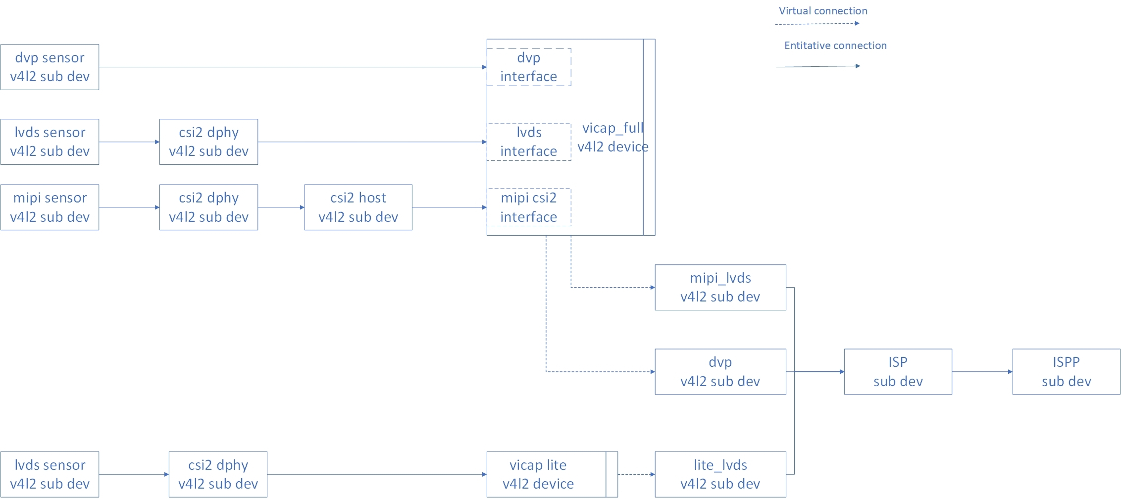
ISP 与 VICAP 连接拓扑 — 英文原图,PDF 第 10 页
4. RKISP 驱动
4.1 框架简述
RKISP 驱动主要基于 v4l2/media 框架,实现硬件配置、中断处理、缓冲区轮转控制,以及 MIPI DPHY、sensor 等子设备的上下电控制。
下图描述 RKISP 驱动的拓扑结构:
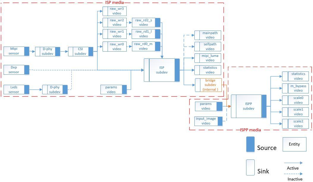
RKISP 驱动拓扑 — 英文原图,PDF 第 11 页
| 名称 | 类型 | 说明 |
|---|---|---|
| rkisp_mainpath | v4l2_vdevcapture | 格式:YUV、RAW Bayer;支持:裁剪、缩放(RAW 不支持缩放) |
| rkisp_selfpath | v4l2_vdevcapture | 格式:YUV、RGB;支持:裁剪、缩放(RAW 不支持缩放) |
| rkisp-isp-subdev | v4l2_subdev | ISP 内部模块,支持 source/sink pad 裁剪。sink pad 的格式、尺寸等于 sensor 输入格式、尺寸;若输出为 raw Bayer,source pad 格式应等于 vdev 输出格式,否则应为 YUYV2X8。source pad 尺寸应小于或等于 sink pad。 |
| rkisp-mipi-luma | v42_vdevcapture | 提供 raw 图像亮度 |
| rkisp-statistics | v4l2_vdevcapture | 提供图像颜色统计信息 |
| rkisp-input-params | v4l2_vdevoutput | 接收 AWB、BLC 等图像增强模块参数 |
| rkisp_rawrd0_m | v4l2_vdevoutput | 从 DDR 读取 raw 图像到 ISP,通常用于 HDR 中帧 |
| rkisp_rawrd1_l | v4l2_vdevoutput | 从 DDR 读取 raw 图像到 ISP,通常用于 HDR 长帧 |
| rkisp_rawrd2_s | v4l2_vdevoutput | 从 DDR 读取 raw 图像到 ISP,通常用于 HDR 短帧 |
| rkisp-csi-subdev | v4l2_subdev | 配置 MIPI CSI |
| rkisp_rawwr0 | v4l2_vdevcapture | 将 sensor raw 图像写入 DDR,通常用于 HDR 中帧 |
| rkisp_rawwr1 | v4l2_vdevcapture | 将 sensor raw 图像写入 DDR,通常用于 HDR 长帧 |
| rkisp_rawwr2 | v4l2_vdevcapture | 将 sensor raw 图像写入 DDR,通常用于 HDR 短帧 |
| rkisp_rawwr3 | v4l2_vdevcapture | 将 sensor raw 图像写入 DDR |
| rockchip-mipi-dphy-rx | v4l2_subdev | 配置 MIPI-DPHY |
| rkisp-bridge-ispp | v4l2_subdev | ISP 向 ISPP 输出 YUV 图像 |
| rkispp_input_image | v4l2_vdevoutput | 从 DDR 读取 YUV 图像到 ISPP |
| rkisp-isp-subdev | v4l2_subdev | sink pad 的格式与尺寸等于 ISP 输出。最大支持 4416x3312,最小 66x258。 |
| rkispp_m_bypass | v4l2_vdev capture |
全分辨率 YUV 格式 |
| 名称 | 类型 | 说明 |
|---|---|---|
| rkispp_scale0 | v4l2_vdev capture |
完整或缩放分辨率,YUV 格式;缩放比例范围:[1 8];YUV422 最大宽度 3264,YUV420 最大宽度 2080;仅适用于 rv1126 |
| rkispp_scale1 | v4l2_vdev capture |
完整或缩放分辨率,YUV 格式;缩放比例范围:[2 8];最大宽度 1280;仅适用于 rv1126 |
| rkispp_scale2 | v4l2_vdev capture |
完整或缩放分辨率,YUV 格式;缩放比例范围:[2 8];最大宽度 1280;仅适用于 rv1126 |
4.2 ISP HDR 模式说明
RKISP2 支持接收 MIPI sensor 输出的 HDR 三帧或两帧模式。硬件通过 3 或 2 路 dmatx 将数据采集到 DDR,再通过 3 或 2 路 dmarx 读入 ISP,由 ISP 完成三帧或两帧合成。驱动链路如下:
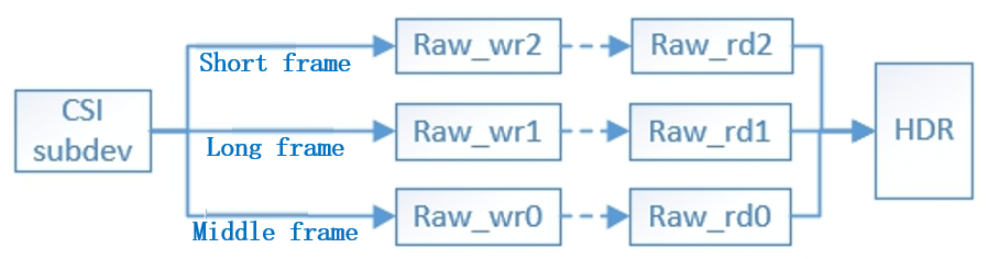
三帧 HDR 链路 — 英文原图,PDF 第 13 页
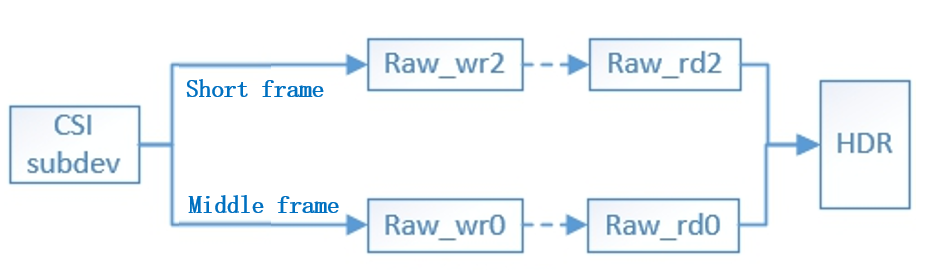
两帧 HDR 链路 — 英文原图,PDF 第 13 页
CSI subdev 通过 get_fmt 获取 sensor 驱动以多个 pad format 提供的输出信息,这些信息对应 CSI 的 source pad。
MIPI sensor 驱动的具体配置请参见“驱动移植步骤”。
| 名称 | 名称 | 说明 |
|---|---|---|
| rkisp-isp-subdev | Sensor pad0 | ISP 采集 sensor vc0(默认)输出的宽、高、格式,常用于线性模式。 |
| rkisp_rawwr0 | Sensor pad1 |
Rawwr0 采集 sensor vcX 输出的宽、高与格式 |
| rkisp_rawwr1 | Sensor pad2 |
Rawwr1 采集 sensor vcX 输出的宽、高与格式 |
| rkisp_rawwr2 | Sensor pad3 |
Rawwr2 采集 sensor vcX 输出的宽、高与格式 |
| rkisp_rawwr3 | Sensor pad4 |
Rawwr3 采集 sensor vcX 输出的宽、高与格式 |
5. RKVICAP 驱动
5.1 框架说明
RKVICAP 驱动主要基于 v4l2/media 框架,实现硬件配置、中断处理、缓冲区轮转控制,以及 MIPI DPHY、sensor 等子设备的上下电控制。
RV1126/RV1109 的 VICAP 有两个 IP 核,分别称为 VICAP FULL 和 VICAP LITE。VICAP FULL 有 dvp/mipi/lvds 三个接口;dvp 可以与 mipi 或 lvds 同时工作,但 mipi 与 lvds 不能同时工作。VICAP LITE 仅有 lvds 接口,可与 VICAP FULL 接口同时工作。VICAP FULL 的 dvp 接口对应 rkvicap_dvp 节点,mipi/lvds 接口对应 rkvicap_mipi_lvds 节点;VICAP LITE 对应 rkvicap_lite_mipi_lvds 节点。各节点可独立采集。
RK356X 的 VICAP 仅有单核,包含 dvp 和 mipi 两个接口。dvp 对应 rkvicap_dvp 节点,mipi 对应 rkvicap_mipi_lvds 节点(名称与 RV1126/RV1109 的 VICAP FULL 相同),各节点可以独立采集。
为将 VICAP 采集的数据同步给 ISP 驱动,需要把 VICAP 驱动生成的逻辑 sditf 节点连接到 ISP 生成的虚拟节点设备。DVP 对应 rkvicap_dvp_sditf,VICAP FULL 的 mipi/lvds 对应 rkvicap_mipi_lvds_sditf,VICAP LITE 对应 rkvicap_lite_sditf。
各接口的具体 DTS 链接方法请参见“CIS 设备注册(DTS)”。
下图描述 RKVICAP 驱动设备的拓扑结构:
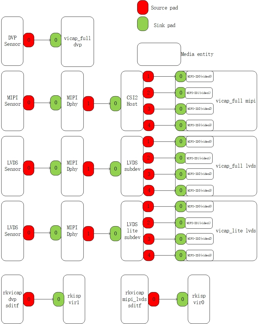
VICAP 接口拓扑 — 英文原图,PDF 第 15 页
6. RK3588 VI 结构
7. 硬件框图
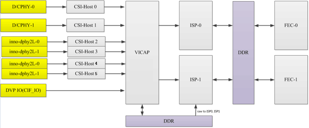
RK3588 VI 硬件框图 — 英文原图,PDF 第 16 页
7.1 多 sensor 支持
单个硬件 ISP 最多支持四路复用,ISP 复用支持的分辨率如下:
两路复用:最大分辨率 3840x2160,DTS 对应配置两路 rkisp_vir 设备。
三路或四路复用:最大分辨率 2560x1536,DTS 对应配置三路或四路 rkisp_vir 设备。
硬件最多支持采集 7 个 sensor:6MIPI + 1DVP,多 sensor 软件路径如下:
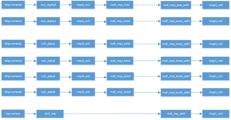
RK3588 多传感器链路 — 英文原图,PDF 第 16 页
框图说明:
(1) RK3588 支持两个 DCPHY,节点名为 csi2_dcphy0/csi2_dcphy1。每个 DCPHY 硬件同时支持 RX/TX,RX 用于摄像头输入,支持 DPHY/CPHY 协议复用。同一 DCPHY 的 TX/RX 必须同时使用 DPHY 或同时使用 CPHY,其他参数见 RK3588 数据手册。
(2) RK3588 支持两个 DPHY 硬件,此处称 dphy0_hw/dphy1_hw,均支持 Full Mode 和 Split Mode。
- dphy0_hw:Full Mode 节点名 csi2_dphy0,最多 4 lanes;Split Mode 拆为 csi2_dphy1(使用 0/1 lane)与 csi2_dphy2(使用 2/3 lane),各最多 2 lanes。Full Mode 按 csi2_dphy1 链路配置,但节点名改为 csi2_dphy0,软件通过 PHY 序号区分模式。
- dphy1_hw:Full Mode 节点名 csi2_dphy3,最多 4 lanes;Split Mode 拆为 csi2_dphy4(使用 0/1 lane)与 csi2_dphy5(使用 2/3 lane),各最多 2 lanes。Full Mode 按 csi2_dphy4 链路配置,但节点名改为 csi2_dphy3,软件通过 PHY 序号区分模式。
(3) 使用上述 MIPI PHY 节点,需配置对应物理节点 csi2_dcphy0_hw/csi2_dcphy1_hw/csi2_dphy0_hw/csi2_dphy1_hw。
(4) 每个 MIPI PHY 需要 CSI2 模块解析 MIPI 协议,节点名为 mipi0_csi2~mipi5_csi2。
(5) RK3588 所有摄像头数据均需通过 VICAP 连接 ISP。仅有一个 VICAP 硬件,支持 6 个 MIPI PHY 和 1 路 DVP 同时输入,因此划分为 rkcif_mipi_lvds~rkcif_mipi_lvds5、rkcif_dvp 等 7 个节点。各节点绑定关系必须严格按框图节点序号配置。
(6) 各 VICAP 节点与 ISP 通过对应虚拟 XXX_sditf 表示链路关系。
(7) RK3588 支持两个 ISP 硬件,各可虚拟出多个节点,软件从 DDR 依次读取图像送入 ISP。多摄像头场景建议将数据流均匀分配到两个 ISP。
(8) 直通与回读模式:
- 直通:VICAP 采集后直接送入 ISP,不存 DDR。HDR 直通时只有短帧真正直通,长帧仍存 DDR 并由 ISP 读取。
- 回读:VICAP 将数据采集至 DDR,应用获得数据后将 buffer 地址推给 ISP,由 ISP 从 DDR 读取图像。
- DTS 仅配置一个虚拟节点时,一个 ISP 硬件默认使用直通;配置多个虚拟节点时默认回读。
7.2 双 ISP 合成支持 8K 分辨率
VICAP 采集 sensor 的 8K 数据,将左右两幅图分别送到两个 ISP 处理,再输出到 DDR,流程如下:
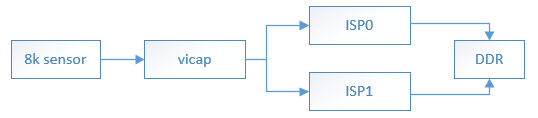
双 ISP 8K 合成 — 英文原图,PDF 第 18 页
当分辨率大于 16M(4672x3504)时,需要同时使用两个 ISP 处理一幅图像,且只支持单摄。
1. 在 rk3588s.dtsi 中可找到 rkisp0、rkisp1 和 rkisp_unite 三个定义。当待处理的分辨率大于 16M 时,需要关闭 rkisp0 和 rkisp1 节点,启用 rkisp_unite,同时修改对应 iommu 节点。
2. 使用 rkisp_unite 节点也可以虚拟出多个节点,此时不论分辨率大小,同一幅图像都裁成左右两幅,送到两个 ISP 处理,再合成为一路输出。
3. DTS 配置参考(原文标记:待链接)。
7.3 8 目 MIPI sensor 支持
RK3588 硬件最多支持 6 个 MIPI sensor,可通过 RK1608 拼接扩展。RK1608 支持 4 路 MIPI 输入(1、2、4lane)和两路 MIPI 输出(1、2、4lane);经 RK1608 拼接的 3 路加原有 5 路 MIPI,可实现 8 路 MIPI sensor 输入,硬件连接如下:
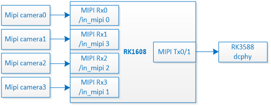
RK1608 八路 MIPI 传感器连接 — 英文原图,PDF 第 18 页
软件上需要在内核 defconfig 中启用 RK1608 驱动:
  CONFIG_VIDEO_ROCKCHIP_PREISP=y
  CONFIG_VIDEO_PREISP_DUMMY_SENSOR=y
在 DTS 链路中,RK1608 抽象为 RK1608 dphy 节点,作为虚拟 preisp_dmy sensor 输入。RK1608 dphy 与普通 sensor 一样接到 RK3588 dcphy,形成 RK1608->dcphy->csi->cif lvds 链路。实际挂在 RK1608 上的 sensor 在 DTS 中直接挂到 rkcif_mipi_lvdsx_sditf、rkcif_mipi_lvdsx_sditf_vir1、rkcif_mipi_lvdsx_sditf_vir2、rkcif_mipi_lvdsx_sditf_vir3 的 port0,作为 SDITF 设备输入。
SDITF 输出与原有路径一致,对应 ISP 节点;DTS 链路如下:
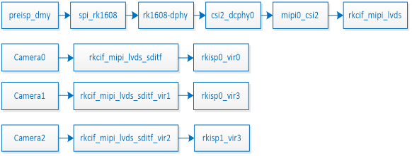
RK1608 DTS 链路拓扑 — 英文原图,PDF 第 19 页
RK1608 的 DTS 配置主要位于 rk1608-dpy 设备节点,包括输入、输出通道和分辨率,如下:
  #define LINK_FREQ               700000000
      mipidphy0: mipidphy0 {
      compatible =  "rockchip,rk1608-dphy";
          status = "okay";
          //rockchip,grf = <&grf>;
          id = <0>;  //RK1608 internal ID (0-2, spliced sequentially by ID)
          cam_nums = <1>;
          in_mipi = <1>;         //Input MIPI channel of the first sensor (0-3)
          out_mipi = <0>;        //Output MIPI channel (0-1)
          link-freqs = /bits/ 64 <LINK_FREQ>; //MIPI rate
          sensor_i2c_bus = <5>;     //The 8-mesh pattern is invalid
          sensor_i2c_addr = <0x1a>; //The 8-mesh pattern is invalid
          sensor-name = "IMX464";
          rockchip,camera-module-index = <9>; //Same as ordinary sensor
          rockchip,camera-module-facing = "back";
          rockchip,camera-module-name = "TongJu";
          rockchip,camera-module-lens-name = "CHT842-MD";
          /* virtual-sensor mode */
          virtual-sub-sensor-config-0 {  //Configuration information for the second
  sensor
              id = <1>;  //RK1608 internal ID (0-2, spliced by ID)
              in_mipi = <2>;
              out_mipi = <1>;
          };
          virtual-sub-sensor-config-1 { //Configuration information for the third
  sensor
              id = <2>;  //RK1608 internal ID (0-2, spliced by ID)
              in_mipi = <3>;
              out_mipi = <1>;
          };
          /* multi-sensor mode end */
          format-config-0 {
              data_type = <0x2b>;
              mipi_lane = <2>;     //The number of lanes connected to the sensor
              mipi_lane_out = <4>; //The number of lanes output by RK1608
              field = <1>;      //The following is the same as the normal sensor
  configuration
              colorspace = <8>;
              code = <MEDIA_BUS_FMT_SRGGB10_1X10>;
              width = <2712>;  //Sensor output resolution
              height= <1538>;
              hactive = <2712>; //RK1608 output resolution, the same width, height
  is n*sensor
              vactive = <4614>;
              htotal = <3616>; //After increasing the width and height of blank,
  30% of the blank is generally required
              vtotal = <4710>;
              inch0-info = <2712 1538 0x2b 0x2b 1>; //Sensor output resolution
              outch0-info = <2712 4614 0x2b 0x2b 1>; //RK1608 output resolution
              hcrop = <2560>; //Single resolution after cropping
              vcrop = <1520>;
          };
          ...
Sensor 的 DTS 配置参考如下:
  &rkcif_mipi_lvds_sditf {
      #address-cells = <1>;
      #size-cells = <0>;
      status = "okay";
      rockchip,combine-index = <0>; //Order in RK1608 stitching diagram
      ports {
          #address-cells = <1>;
          #size-cells = <0>;
          port@0 {
              reg = <0>;
              #address-cells = <1>;
              #size-cells = <0>;
              mipi_lvds_sditf_in: endpoint@1 {
                  reg = <1>;
                  remote-endpoint = <&imx464_out7>;
                  data-lanes = <1 2>;
              };
          };
          port@1 {
              reg = <1>;
              #address-cells = <1>;
              #size-cells = <0>;
              mipi_lvds_sditf: endpoint@0 {
                  reg = <0>;
                  remote-endpoint = <&isp0_vir0>;
              };
          };
      };
  };
8. CIS(CMOS 图像传感器)驱动
8.1 CIS 设备注册(DTS)
8.1.1 MIPI 接口
对于 RV1126 和 RV1106 平台,有两个独立完整的标准物理 MIPI CSI2 DPY,对应 DTS 的 csi_dphy0 和 csi_dphy1(参见 RV1126.DTSI),特性如下:
数据 lane 最多为 4。
最大速率 2.5Gbps/lane。
RK356X 平台只有一个标准物理 MIPI CSI2 dphy,可工作于 full 和 split 两种模式,并划分为 csi2_dphy0/csi2_dphy1/csi2_dphy2 三个逻辑 dphy(参见 rk3568.dtsi),特性如下:
完整模式(Full mode)
仅使用 csi2_dphy0;它与 csi2_dphy1/csi2_dphy2 互斥,不能同时使用。
数据 lane 最多为 4。
最大速率 2.5Gbps/lane。
拆分模式(Split mode)
仅使用 csi2_dphy1 和 csi2_dphy2;与 csi2_dphy0 互斥,不能同时使用。
csi2_dphy1 和 csi2_dphy2 可同时使用;
csi2_dphy1 和 csi2_dphy2 各最多 2 条数据 lane。
csi2_dphy1 对应物理 DPY 的 lane0/lane1。
csi2_dphy2 对应物理 DPY 的 Lane2/LANE3。
最高速率为 2.5Gbps/lane。
具体 DTS 用例参见以下示例。
8.1.1.1 连接 ISP
8.1.1.1.1 RV1126/RV1106
以下以 RV1126 ISP 和 OS04A10 为例。
链接关系:sensor->csi_dphy->isp->ispp
arch/arm/boot/dts/rv1126-evb-v10.dtsi
配置要点
data-lanes 必须指明实际使用的 lane 数,否则无法识别为 MIPI 类型。
  cam_ircut0: cam_ircut {
      status = "okay";
      compatible = "rockchip,ircut";
      ircut-open-gpios = <&gpio2 RK_PA7 GPIO_ACTIVE_HIGH>;
      ircut-close-gpios = <&gpio2 RK_PA6 GPIO_ACTIVE_HIGH>;
      rockchip,camera-module-index = <1>;
      rockchip,camera-module-facing = "front";
  };
  os04a10: os04a10@36 {
      compatible = "ovti,os04a10";// It needs to match the matching string in the
  driver
      reg = <0x36>;// sensor I2C device address, 7 bits
      clocks = <&cru CLK_MIPICSI_OUT>;// Sensor clickin configuration
      clock-names = "xvclk";
      power-domains = <&power RV1126_PD_VI>;
      pinctrl-names = "rockchip,camera_default";
      pinctrl-0 = <&mipi_csi_clk0>;// PINCTL settings
      //power supply
      avdd-supply = <&vcc_avdd>;
      dovdd-supply = <&vcc_dovdd>;
      dvdd-supply = <&vcc_dvdd>;
      // Power pin assignment and active level
      pwdn-gpios = <&gpio1 RK_PD4 GPIO_ACTIVE_HIGH>;
      // Module number, which should not be repeated
      rockchip,camera-module-index = <1>;
      // Module orientation, with "back" and "front"
      rockchip,camera-module-facing = "front";
      // Module name
      rockchip,camera-module-name = "CMK-OT1607-FV1";
      // Lens name
      rockchip,camera-module-lens-name = "M12-4IR-4MP-F16";
      //IR CUT equipment
      ir-cut = <&cam_ircut0>;
      port {
          ucam_out0: endpoint {
              // The port name on the mipi dphy side
              remote-endpoint = <&mipi_in_ucam0>;
              // MIPI lanes number, 1 lane is <1>,
              4lane is <1 2 3 4 >
              data-lanes = <1 2 3 4>;
          };
      };
   };
  &csi_dphy0 {
      status = "okay";
      ports {
          #address-cells = <1>;
          #size-cells = <0>;
          port@0 {
              reg = <0>;
              #address-cells = <1>;
              #size-cells = <0>;
              mipi_in_ucam0: endpoint@1 {
                  reg = <1>;
                  // The port name on the sensor side
                  remote-endpoint = <&ucam_out0>;
                  // MIPI lanes number, 1 lane is <1>, 4lane is
  <1 2 3 4 >,data-lanes = <1 2 3 4>;
              };
          };
          port@1 {
              reg = <1>;
              #address-cells = <1>;
              #size-cells = <0>;
              csidphy0_out: endpoint@0 {
                  reg = <0>;
                  // The port name on the ISP side
                  remote-endpoint = <&isp_in>;
              };
          };
      };
  };
  &rkisp {
      status = "okay";
  };
  &rkisp_vir0 {
      status = "okay";
      ports {
          #address-cells = <1>;
          #size-cells = <0>;
          port@0 {
              reg = <0>;
              #address-cells = <1>;
              #size-cells = <0>;
              isp_in: endpoint@0 {
                  reg = <0>;
                  // The port name on the mipi dphy side
                  remote-endpoint = <&csidphy0_out>;
              };
          };
          port@1 {
              reg = <1>;
              #address-cells = <1>;
              #size-cells = <0>;
              isp0_out: endpoint@1 {
                  reg = <1>;
                  // ISP port name, ISP output to ISP
                  remote-endpoint = <&ispp0_in>;
              };
          };
      };
  };
  &rkispp {
      status = "okay";
  };
  &rkispp_vir0 {
      status = "okay";
      port {
          #address-cells = <1>;
          #size-cells = <0>;
          Ispp0_in: endpoint@0 {
              reg = <0>;
              // ISP port name, ISPP input
              remote-endpoint = <&isp0_out>;
          };
      };
  };
8.1.1.1.2 RK356X
以下以 RK3566 ISP 和 GC8034 4LANE 为例:
链路关系:sensor->csi2_dphy0->isp。配置要点:
需要配置 data-lanes。
需要启用 csi2_dphy_hw 节点。
   /* full mode: lane0-3 */
      gc8034: gc8034@37 {
          // It needs to match the matching string in the driver
          compatible = "galaxycore,gc8034";
          status = "okay";
          // sensor I2C device address, 7 bits
          reg = <0x37>;
          // Sensor mclk source configuration
          clocks = <&cru CLK_CIF_OUT>;
          clock-names = "xvclk";
          //The sensor dependent power domain is enabled
          power-domains = <&power RK3568_PD_VI>;
          //Sensor McLk pinctl settings
          pinctrl-names = "default";
          pinctrl-0 = <&cif_clk>;
          // Reset pin assignment and active level
          reset-gpios = <&gpio3 RK_PA6 GPIO_ACTIVE_LOW>;
          // Powerdown pin assignment and active level
          pwdn-gpios = <&gpio4 RK_PB2 GPIO_ACTIVE_LOW>;
          // Module number, which should not be repeated
          rockchip,camera-module-index = <0>;
          // Module orientation, with "back" and "front"
          rockchip,camera-module-facing = "back";
          // Module name
          rockchip,camera-module-name = "RK-CMK-8M-2-v1";
          // Lens name
          rockchip,camera-module-lens-name = "CK8401";
          port {
              gc8034_out: endpoint {
                  // The port name of the CSI2 dphy end
                  remote-endpoint = <&dphy0_in>;
                  // CSI2 dphy lane number, 1lane is <1>,
                  4lane is <1 2 3 4>, data-lanes = <1 2 3 4>;
              };
          };
      };
      &csi2_dphy_hw {
         status = "okay";
      };
      &csi2_dphy0 {
          //csi2_dphy0 is not used at the same time as
          csi2_dphy1/csi2_dphy2, mutually exclusive
          status = "okay";
          /*
           * dphy0 only used for full mode,
           * full mode and split mode are mutually exclusive
           */
          ports {
              #address-cells = <1>;
              #size-cells = <0>;
              port@0 {
                  reg = <0>;
                  #address-cells = <1>;
                  #size-cells = <0>;
                  dphy0_in: endpoint@1 {
                      reg = <1>;
                      // The port name on the sensor side
                      remote-endpoint = <&gc8034_out>;
                      // CSI2 dphy lanes, 1 lane is <1 >, 4 lanes is <1 2 3 4 >,
  which needs to be consistent with the sensor side
                          data-lanes = <1 2 3 4>;
                  };
              };
              port@1 {
                  reg = <1>;
                  #address-cells = <1>;
                  #size-cells = <0>;
                  dphy0_out: endpoint@1 {
                      reg = <1>;
                      // The port name on the ISP side
                      remote-endpoint = <&isp0_in>;
                  };
              };
          };
      };
  &rkisp {
      status = "okay";
  };
  &rkisp_mmu {
      status = "okay";
  };
  &rkisp_vir0 {
      status = "okay";
      port {
          #address-cells = <1>;
          #size-cells = <0>;
          isp0_in: endpoint@0 {
              reg = <0>;
              // The port name of the CSI2 dphy side
              remote-endpoint = <&dphy0_out>;
          };
      };
  };
8.1.1.2 连接 VICAP
8.1.1.2.1 RV1126/RV1109
以 MIPI OS04A10 4 Lanes 连接 VICAP 为例:
链路关系:sensor->csi dphy->mipi csi host->vicap。配置要点:
data-lanes 必须指明实际使用的 lane 数,否则无法识别为 MIPI 类型。
dphy 需要连接 CSI Host 节点。
  os04a10: os04a10@36 {
          // It needs to match the matching string in the driver
          compatible = "ovti,os04a10";
          // sensor I2C device address, 7 bits
          reg = <0x36>;
          // Sensor mclk source configuration
          clocks = <&cru CLK_MIPICSI_OUT>;
          clock-names = "xvclk";
          //The sensor dependent power domain is enabled
          power-domains = <&power RV1126_PD_VI>;
          avdd-supply = <&vcc_avdd>;
          dovdd-supply = <&vcc_dovdd>;
          dvdd-supply = <&vcc_dvdd>;
          //Sensor McLk pinctl settings
          pinctrl-names = "rockchip,camera_default";
          pinctrl-0 = <&mipicsi_clk0>;
          // Powerdown pin assignment and active level
          pwdn-gpios = <&gpio1 RK_PD4 GPIO_ACTIVE_HIGH>;
          // Module number, which should not be repeated
          rockchip,camera-module-index = <1>;
          // Module orientation, with "back" and "front"
          rockchip,camera-module-facing = "front";
          // Module name
          rockchip,camera-module-name = "CMK-OT1607-FV1";
          // Lens name
          rockchip,camera-module-lens-name = "M12-40IRC-4MP-F16";
          // Ircut name
          ir-cut = <&cam_ircut0>;
          port {
              ucam_out0: endpoint {
                  // The port name of the CSI2 dphy end
                  remote-endpoint = <&mipi_in_ucam0>;
                  // CSI2 dphy lanes number, 1lane is <1>, 4lane is <1 2 3 4 >
                  data-lanes = <1 2 3 4>;
              };
          };
      };
  &csi_dphy0 {
      //csi2_dphy0 is not used at the same time as csi2_dphy1/csi2_dphy2, mutually exclusive
      status = "okay";
      ports {
          #address-cells = <1>;
          #size-cells = <0>;
          port@0 {
              reg = <0>;
              #address-cells = <1>;
              #size-cells = <0>;
              mipi_in_ucam0: endpoint@1 {
                  reg = <1>;
                  // The port name on the sensor side
                  remote-endpoint = <&ucam_out0>;
                  // CSI2 dphy lanes, 1 lane is <1 >, 4 lanes is <1 2 3 4 >, which
  needs to be consistent with the sensor side
                  data-lanes = <1 2 3 4>;
              };
          };
          port@1 {
              reg = <1>;
              #address-cells = <1>;
              #size-cells = <0>;
              csidphy0_out: endpoint@0 {
                  reg = <0>;
                  // The port name of the CSI2 host
                  remote-endpoint = <&mipi_csi2_input>;
              };
          };
      };
  };
  &mipi_csi2 {
      status = "okay";
      ports {
          #address-cells = <1>;
          #size-cells = <0>;
          port@0 {
              reg = <0>;
              #address-cells = <1>;
              #size-cells = <0>;
              mipi_csi2_input: endpoint@1 {
                  reg = <1>;
                  // The port name of the CSI2 host
                  remote-endpoint = <&csidphy0_out>;
                  // CSI2 host lanes, 1 lane is <1>,
                  4lane is <1 2 3 4 >, which needs to be
                  consistent with the sensor side
                  data-lanes = <1 2 3 4>;
              };
          };
          port@1 {
              reg = <1>;
              #address-cells = <1>;
              #size-cells = <0>;
              mipi_csi2_output: endpoint@0 {
                  reg = <0>;
                  // The port name on the vicap side
                  remote-endpoint = <&cif_mipi_in>;
                  // CSI2 host lanes, 1 lane is <1>,
                  4lane is <1 2 3 4 >, which needs to be
                  consistent with the sensor side
                  data-lanes = <1 2 3 4>;
              };
          };
      };
  };
  &rkcif_mipi_lvds {
      status = "okay";
      port {
          /* MIPI CSI-2 endpoint */
          cif_mipi_in: endpoint {
              // The port name of the CSI2 host
              remote-endpoint = <&mipi_csi2_output>;
              // The number of lanes on the vicap side,
              1 lane is <1 >, 4lane is < 1 2 3 4 >,
              which needs to be consistent with the sensor side
              data-lanes = <1 2 3 4>;
          };
      };
  };
  &rkcif_mipi_lvds_sditf {
      status = "okay";
      port {
          /* sditf endpoint */
          mipi_lvds_sditf: endpoint {
              //ISP virtual device port name
              remote-endpoint = <&isp_in>;
              //The number of lanes of MIPI CSI2 dphy,
              consistent with the sensor
              data-lanes = <1 2 3 4>;
          };
      };
  };
  &rkisp {
      status = "okay";
  };
  &rkisp_vir0 {
      status = "okay";
      ports {
          port@0 {
              reg = <0>;
              #address-cells = <1>;
              #size-cells = <0>;
              isp_in: endpoint@0 {
                  reg = <0>;
                  //The endpoint name of the Vicap SDITF
                  remote-endpoint = <&mipi_lvds_sditf>;
              };
          };
      };
  };
8.1.1.2.2 RK356X
以 GC5025 2lane 连接 rk3566 EVB2 MIPI CSI2 dphy 的 lane2/lane3 为例:
链路关系:sensor->csi2 dphy->mipi CSI host->vicap。配置要点:
data-lanes 必须指明实际使用的 lane 数,否则无法识别为 MIPI 类型。
dphy 需要连接 CSI Host 节点。
需要启用 CSI2 dphy HW 节点。
  /* split mode: lane:2/3 */
  gc5025: gc5025@37 {
          status = "okay";
          // It needs to match the matching string in the driver
          compatible = "galaxycore,gc5025";
          // sensor I2C device address, 7 bits
          reg = <0x37>;
          // Sensor mclk source configuration
          clocks = <&pmucru CLK_WIFI>;
          clock-names = "xvclk";
          //Sensor McLk pinctl settings
          pinctrl-names = "default";
          pinctrl-0 = <&refclk_pins>;
          // Reset pin assignment and active level
          reset-gpios = <&gpio3 RK_PA5 GPIO_ACTIVE_LOW>;
          // Powerdown pin assignment and active level
          pwdn-gpios = <&gpio3 RK_PB0 GPIO_ACTIVE_LOW>;
          // The sensor dependent power domain is enabled
          power-domains = <&power RK3568_PD_VI>;
          /*power-gpios = <&gpio0 RK_PC1 GPIO_ACTIVE_HIGH>;*/
          // Module number, which should not be repeated
          rockchip,camera-module-index = <1>;
          // Module orientation, with "back" and "front"
          rockchip,camera-module-facing = "front";
          // Module name
          rockchip,camera-module-name = "TongJu";
          // Lens name
          rockchip,camera-module-lens-name = "CHT842-MD";
          port {
              gc5025_out: endpoint {
                  // The port name of the CSI2 dphy end
                  remote-endpoint = <&dphy2_in>;
                  // CSI2 dphy lanes number, 2lanes are <1 2>, 4lanes are <1 2 3 4
  >
                  data-lanes = <1 2>;
              };
          };
  };
   &csi2_dphy_hw {
           status = "okay";
   };
  &csi2_dphy2 {
      //csi2_dphy2 is not used at the same time as csi2_dphy0, mutually exclusive;
  Can be used in parallel with csi2_dphy1
      status = "okay";
      /*
       * dphy2 only used for split mode,
       * can be used  concurrently  with dphy1
       * full mode and split mode are mutually exclusive
       */
      ports {
          #address-cells = <1>;
          #size-cells = <0>;
          port@0 {
              reg = <0>;
              #address-cells = <1>;
              #size-cells = <0>;
              dphy2_in: endpoint@1 {
                  reg = <1>;
                  // The port name on the sensor side
                  remote-endpoint = <&gc5025_out>;
                  // CSI2 dphy lanes, 2lane is <1 2>, 4lane is <1 2 3 4 >, which
  needs to be consistent with the sensor side
                  data-lanes = <1 2>;
              };
          };
          port@1 {
              reg = <1>;
              #address-cells = <1>;
              #size-cells = <0>;
              dphy2_out: endpoint@1 {
                  reg = <1>;
                  // The port name of the CSI2 host
                  remote-endpoint = <&mipi_csi2_input>;
              };
          };
      };
  };
  &mipi_csi2 {
      status = "okay";
      ports {
          #address-cells = <1>;
          #size-cells = <0>;
          port@0 {
              reg = <0>;
              #address-cells = <1>;
              #size-cells = <0>;
              mipi_csi2_input: endpoint@1 {
                  reg = <1>;
                  // The port name on the CSI2 dphy side
                  remote-endpoint = <&dphy2_out>;
                  // CSI2 host lanes, 2 lanes are <1 2>, 4lanes are <1 2 3 4 >,
  which need to be consistent with the sensor side
                  data-lanes = <1 2>;
              };
          };
          port@1 {
              reg = <1>;
              #address-cells = <1>;
              #size-cells = <0>;
              mipi_csi2_output: endpoint@0 {
                  reg = <0>;
                  // The port name on the vicap side
                  remote-endpoint = <&cif_mipi_in>;
                  // CSI2 host lanes, 1 lane is <1>, 4lane is <1 2 3 4 >, which
  needs to be consistent with the sensor side
                  data-lanes = <1 2>;
              };
          };
      };
  };
  &rkcif_mipi_lvds {
      status = "okay";
      port {
          cif_mipi_in: endpoint {
              // The port name of the CSI2 host
              remote-endpoint = <&mipi_csi2_output>;
              // The number of lanes on the vicap side, 2lane is <1 2>, 4lane is <1
  2 3 4 >, which needs to be consistent with the sensor side
              data-lanes = <1 2>;
          };
      };
  };
  &rkcif_mipi_lvds_sditf {
      status = "okay";
      port {
          /* MIPI CSI-2 endpoint */
          mipi_lvds_sditf: endpoint {
              //ISP virtual device port name
              remote-endpoint = <&isp_in>;
              //The number of lanes of MIPI CSI2 dphy, consistent with the sensor
              data-lanes = <1 2>;
          };
      };
  };
  &rkisp {
      status = "okay";
  };
  &rkisp_vir0 {
      status = "okay";
      ports {
          port@0 {
              reg = <0>;
              #address-cells = <1>;
              #size-cells = <0>;
              isp_in: endpoint@0 {
                  reg = <0>;
                  //The endpoint name of Vicap Mipi SDITF
                  remote-endpoint = <&mipi_lvds_sditf>;
              };
          };
      };
  };
8.1.1.2.3 RK3588
以 IMX464 连接 DPY1 为例。
data-lanes 必须指明实际使用的 lane 数,否则无法识别为 MIPI 类型。
dphy 需要连接 CSI Host 节点,csi2_dphy3 对应使用 mipi4_csi2。
csi2_dphy3 只是逻辑节点,需要依赖物理节点 csi2_dphy1_hw。
rkcif_mipi_lvds4 是 VICAP 的逻辑节点之一,需要配置物理节点 rkcif 及对应 iommu。
rkcif_mipi_lvds4_sditf 是用于连接 ISP 的 rkcif_mipi_lvds4 虚拟子节点。
Sensor 驱动通常实现 AVDD/DVDD/DOVDD 三路电源操作。类似 RAK809 分配的电源可直接配置在 sensor 节点;若使用 LDO 等外部电源且由 GPIO 控制使能,可参考 vcc_mipicsi1 配成电源节点,通过引用计数上下电,适用于多设备共用电源。多摄时建议 DVD 电源独立供电,AVDD/DOVDD 可共享;DVD 共享且耗电较大时,可能出现瞬时供电不足和电源塌陷,影响画质甚至不出图。原文 RAK809、DVD 拼写保留,需核对实际器件及 DVDD 电源域。
      / {
          vcc_mipicsi1: vcc-mipicsi1-regulator {
              compatible = "regulator-fixed";
              gpio = <&gpio4 RK_PA6 GPIO_ACTIVE_HIGH>;
              pinctrl-names = "default";
              pinctrl-0 = <&mipicsi1_pwr>;
              regulator-name = "vcc_mipicsi1";
              enable-active-high;
          };
      };
      &csi2_dphy1_hw {
          status = "okay";
      };
      &csi2_dphy3 {
          status = "okay";
          ports {
              #address-cells = <1>;
              #size-cells = <0>;
              port@0 {
                  reg = <0>;
                  #address-cells = <1>;
                  #size-cells = <0>;
                  mipi_in_ucam: endpoint@1 {
                      reg = <1>;
                      remote-endpoint = <&imx464_out>;
                      data-lanes = <1 2 3 4>;
                  };
              };
              port@1 {
                  reg = <1>;
                  #address-cells = <1>;
                  #size-cells = <0>;
                  csidphy3_out: endpoint@0 {
                      reg = <0>;
                      remote-endpoint = <&mipi4_csi2_input>;
                  };
              };
          };
      };
      &i2c4 {
          status = "okay";
          pinctrl-0 = <&i2c4m3_xfer>;
          imx464: imx464@36 {
              compatible = "sony,imx464";
              status = "okay";
              reg = <0x36>;
              clocks = <&cru CLK_MIPI_CAMARAOUT_M4>;
              clock-names = "xvclk";
              pinctrl-names = "default";
              pinctrl-0 = <&mipim0_camera4_clk>;
              avdd-supply = <&vcc_mipicsi1>;
              reset-gpios = <&gpio1 RK_PD6 GPIO_ACTIVE_HIGH>;
              pwdn-gpios = <&gpio3 RK_PC1 GPIO_ACTIVE_HIGH>;
              rockchip,camera-module-index = <0>;
              rockchip,camera-module-facing = "back";
              rockchip,camera-module-name = "CMK-OT1980-PX1";
              rockchip,camera-module-lens-name = "SHG102";
              port {
                  imx464_out: endpoint {
                      remote-endpoint = <&mipi_in_ucam>;
                      data-lanes = <1 2 3 4>;
                  };
              };
          };
      };
      &mipi4_csi2 {
          status = "okay";
          ports {
              #address-cells = <1>;
              #size-cells = <0>;
              port@0 {
                  reg = <0>;
                  #address-cells = <1>;
                  #size-cells = <0>;
                  mipi4_csi2_input: endpoint@1 {
                      reg = <1>;
                      remote-endpoint = <&csidphy3_out>;
                  };
              };
              port@1 {
                  reg = <1>;
                  #address-cells = <1>;
                  #size-cells = <0>;
                  mipi4_csi2_output: endpoint@0 {
                      reg = <0>;
                      remote-endpoint = <&cif_mipi_in4>;
                  };
              };
          };
      };
      &pinctrl {
          cam {
              mipicsi1_pwr: mipicsi1-pwr {
                  rockchip,pins =
                      /* camera power en */
                      <4 RK_PA6 RK_FUNC_GPIO &pcfg_pull_none>;
              };
          };
      };
      &rkcif {
          status = "okay";
      };
      &rkcif_mipi_lvds4 {
          status = "okay";
          port {
              cif_mipi_in4: endpoint {
                  remote-endpoint = <&mipi4_csi2_output>;
              };
          };
      };
      &rkcif_mipi_lvds4_sditf {
          status = "okay";
          port {
              mipi4_lvds_sditf: endpoint {
                  remote-endpoint = <&isp0_vir0>;
              };
          };
      };
      &rkcif_mmu {
          status = "okay";
      };
      #if 1
      &rkisp0 {
          status = "okay";
          /* the max input w h and fps of mulit sensor */
          //max-input = <2688 1520 30>;多摄sensor分辨率不一样,需要配置
      };
      &isp0_mmu {
          status = "okay";
      };
      #else //sensor分辨率大于16M(4672x3504)需要2个isp合成处理
      /* dual isp case need width 32 align, height 8 align */
      &rkisp_unite_mmu {
          status = "okay";
      };
      &rkisp_unite {
             status = "okay";
      };
      &rkisp0_vir0 {
             status = "okay";
             rockchip,hw = <&rkisp_unite>;
      };
      #endif
      &rkisp0_vir0 {
          status = "okay";
          port {
              #address-cells = <1>;
              #size-cells = <0>;
              isp0_vir0: endpoint@0 {
                  reg = <0>;
                  remote-endpoint = <&mipi4_lvds_sditf>;
              };
          };
      };
8.1.1.2.4 RV1106
DTS 配置参见 arch/arm/boot/dts/rv1106-evb-cam.dtsi。
8.1.1.2.5 RK3562
DTS 配置参见 arch/arm64/boot/dts/rockchip/rk3562-evb1-cam.dtsi。
8.1.2 LVDS 接口
8.1.2.1 连接 VICAP
8.1.2.1.1 RV1126/RV1109
以 IMX327 4lane 为例,链路关系如下:
链路关系:sensor->csi dphy->vicap。配置要点:
dphy 不需要连接 CSI Host 节点,否则无法接收数据。
data-lanes 必须指明实际使用的 lane 数,否则无法接收数据。
bus-type 必须设为 3,否则不能识别为 LVDS 接口,导致链路建立失败。
  imx327: imx327@1a {
          // It needs to match the matching string in the driver
          compatible = "sony,imx327";
          // sensor I2C device address, 7 bits
          reg = <0x1a>;
          // Sensor mclk source configuration
          clocks = <&cru CLK_MIPICSI_OUT>;
          clock-names = "xvclk";
          //The sensor dependent power domain is enabled
          power-domains = <&power RV1126_PD_VI>;
          avdd-supply = <&vcc_avdd>;
          dovdd-supply = <&vcc_dovdd>;
          dvdd-supply = <&vcc_dvdd>;
          //Sensor McLk pinctl settings
          pinctrl-names = "default";
          pinctrl-0 = <&mipicsi_clk0>;
          // Powerdown pin assignment and active level
          pwdn-gpios = <&gpio3 RK_PA6 GPIO_ACTIVE_HIGH>;
          // Reset pin assignment and active level
          reset-gpios = <&gpio1 RK_PD5 GPIO_ACTIVE_HIGH>;
          // Module number, which should not be repeated
          rockchip,camera-module-index = <1>;
          // Module orientation, with "back" and "front"
          rockchip,camera-module-facing = "front";
          // Module name
          rockchip,camera-module-name = "CMK-OT1607-FV1";
          // Lens name
          rockchip,camera-module-lens-name = "M12-4IR-4MP-F16";
          // Ircut name
          ir-cut = <&cam_ircut0>;
          port {
              ucam_out0: endpoint {
                  // The port name of the CSI2 dphy end
                  remote-endpoint = <&mipi_in_ucam0>;
                  //CSI2 dphy lvds number of lanes, 1 lane is <1>, 4lane is <4 >,
  must be specified
                  data-lanes = <4>;
                  //The type of LVDS interface, which must be specified
                  bus-type = <3>;
              };
          };
  };
  &csi_dphy0 {
      //csi2_dphy0 is not used at the same time as csi2_dphy1/csi2_dphy2, mutually exclusive
      status = "okay";
      ports {
          #address-cells = <1>;
          #size-cells = <0>;
          port@0 {
              reg = <0>;
              #address-cells = <1>;
              #size-cells = <0>;
              mipi_in_ucam0: endpoint@1 {
                  reg = <1>;
                  // The port name on the sensor side
                  remote-endpoint = <&ucam_out0>;
                  //CSI2 dphy lvds number of lanes, 1 lane is <1>, 4lane is <4 >,
  must be specified
                  data-lanes = <4>;
                  //The type of LVDS interface, which must be specified
                  bus-type = <3>;
              };
          };
          port@1 {
              reg = <1>;
              #address-cells = <1>;
              #size-cells = <0>;
              csidphy0_out: endpoint@0 {
                  reg = <0>;
                  // The port name of the vicap lite side
                  remote-endpoint = <&cif_lite_lvds_in>;
                  // CSI2 dphy lvds number of lanes, 1 lane is <1>, 4lane is <4 >,
  must be specified
                  data-lanes = <4>;
                  // The type of LVDS interface, which must be specified
                  bus-type = <3>;
              };
          };
      };
  };
  &rkcif_lite_mipi_lvds {
      status = "okay";
      port {
          /* lvds endpoint */
          cif_lite_lvds_in: endpoint {
              // The port name of the CSI2 dphy end
              remote-endpoint = <&csidphy0_out>;
              // CSI2 dphy lvds number of lanes, 1 lane is <1>, 4lane is <4 >, must
  be specified
              data-lanes = <4>;
              //The type of LVDS interface, which must be specified
              bus-type = <3>;
          };
      };
  };
  &rkcif_lite_sditf {
      status = "okay";
      port {
          /* lvds endpoint */
          lite_sditf: endpoint {
              //ISP virtual device port name
              remote-endpoint = <&isp_in>;
              //CSI2 dphy has the number of lanes, which is the same as the sensor
              data-lanes = <4>;
          };
      };
  };
  &rkisp {
      status = "okay";
  };
  &isp0_mmu {
      status = "okay";
  };
  &rkisp_vir0 {
      status = "okay";
      ports {
          port@0 {
              reg = <0>;
              #address-cells = <1>;
              #size-cells = <0>;
              isp_in: endpoint@0 {
                  reg = <0>;
                  //The endpoint name of the lite vicap lvds sditf
                  remote-endpoint = <&lite_sditf>;
              };
          };
      };
  };
若需要使用双 ISP 处理,可作如下修改:
  &rkisp {
      status = "disabled";
  };
  &isp0_mmu {
      status = "disabled";
  };
  &rkisp_unite {
      status = "okay";
  };
  &rkisp_unite_mmu {
      status = "okay";
  };
  &rkisp0_vir0 {
      status = "okay";
      /* hw is referenced as a unite node*/
      rockchip,hw = <&rkisp_unite>;
      port {
          #address-cells = <1>;
          #size-cells = <0>;
          isp0_vir0: endpoint@0 {
              reg = <0>;
              remote-endpoint = <&mipi4_lvds_sditf>;
          };
      };
  };
8.1.3 DVP 接口
8.1.3.1 连接 VICAP
在 RV1126/RV1109/RK356X/RK3588 平台,DVP 各相关接口的 DTS 配置相同。
8.1.3.1.1 BT601
以 AR0230 BT601 为例,链路关系如下:
链路关系:sensor->vicap。配置要点:
必须配置 hsync-active/vsync-active,v4l2 框架才能异步注册并识别 BT601;不配置时将识别为 BT656。
pclk-sample/bus-width 可选。
Sensor 驱动的 g_mbus_config 接口必须通过 flag 指明当前 sensor 的 hsync-acitve/vsync-active/pclk-ative 有效极性,否则无法接收数据;原文属性拼写需核对。
pinctrl 必须正确引用,为 BT601 相关 GPIO 配置对应 IOMUX,否则无法接收数据。
g_mbus_config 接口示例代码如下:
  static int ar0230_g_mbus_config(struct v4l2_subdev *sd,
                  struct v4l2_mbus_config *config)
  {
      config->type = V4L2_MBUS_PARALLEL;
      config->flags = V4L2_MBUS_HSYNC_ACTIVE_HIGH |
              V4L2_MBUS_VSYNC_ACTIVE_HIGH |
              V4L2_MBUS_PCLK_SAMPLE_FALLING;
      return 0;
  }
DTS 配置示例如下:
  ar0230: ar0230@10 {
          // It needs to match the matching string in the driver
          compatible = "aptina,ar0230";
          // sensor I2C device address, 7 bits
          reg = <0x10>;
          // Sensor mclk source configuration
          clocks = <&cru CLK_CIF_OUT>;
          clock-names = "xvclk";
          //The sensor dependent power domain is enabled
          avdd-supply = <&vcc_avdd>;
          dovdd-supply = <&vcc_dovdd>;
          dvdd-supply = <&vcc_dvdd>;
          power-domains = <&power RV1126_PD_VI>;
          // Powerdown pin assignment and active level
          pwdn-gpios = <&gpio2 RK_PA6 GPIO_ACTIVE_HIGH>;
          /*reset-gpios = <&gpio2 RK_PC5 GPIO_ACTIVE_HIGH>;*/
          //Configure the DVP-related data pins and clock pins
          pinctrl-names = "default";
          pinctrl-0 = <&cifm0_dvp_ctl>;
          // Module number, which should not be repeated
          rockchip,camera-module-index = <0>;
          // Module orientation, with "back" and "front"
          rockchip,camera-module-facing = "back";
          // Module name
          rockchip,camera-module-name = "CMK-OT0836-PT2";
          // Lens name
          rockchip,camera-module-lens-name = "YT-2929";
          port {
              cam_para_out1: endpoint {
                  remote-endpoint = <&cif_para_in>;
              };
          };
  };
  &rkcif_dvp {
      status = "okay";
      port {
          /* Parallel bus endpoint */
          cif_para_in: endpoint {
              //The name of the sensor endpoint
              remote-endpoint = <&cam_para_out1>;
              //Relevant configuration parameters on the sensor side
              bus-width = <12>;
              hsync-active = <1>;
              vsync-active = <1>;
              pclk-sample = <0>;
          };
      };
  };
  &rkcif_dvp_sditf {
      status = "okay";
      port {
          /* parallel endpoint */
          dvp_sditf: endpoint {
              //ISP virtual device port name
              remote-endpoint = <&isp_in>;
              //Relevant configuration parameters on the sensor side
              bus-width = <12>;
              hsync-active = <1>;
              vsync-active = <1>;
              pclk-sample = <0>;
          };
      };
  };
  &rkisp {
      status = "okay";
  };
  &rkisp_vir0 {
      status = "okay";
      ports {
          port@0 {
              reg = <0>;
              #address-cells = <1>;
              #size-cells = <0>;
              isp_in: endpoint@0 {
                  reg = <0>;
                  //The endpoint name of the DVD SDITF
                  remote-endpoint = <&dvp_sditf>;
              };
          };
      };
  };
8.1.3.1.2 BT656/BT1120
BT656/BT1120 的 DTS 用法一致。
以 Ava FPGA BT1120 为例,链路关系如下:
链路关系:sensor->vicap
配置要点
不要配置 hsync-active/vsync-active,否则 v4l2 框架异步注册时会识别为 BT601。
pclk-sample/bus-width 可选。
Sensor 驱动的 g_mbus_config 接口必须通过 flag 变量指明 pclk-ative 的有效极性,否则无法接收数据;保留原文拼写。
必须实现 v4l2_subdev_video_ops 中的 querystd,表明当前接口为 ATSC 接口,否则无法接收数据。
必须实现 RKMODULE_GET_BT656_MBUS_INFO;BT656/BT1120 均调用此 ioctl,接口兼容,实现可参考 drivers/media/i2c/nvp6158_drv/nvp6158_v4l2.c。
pinctrl 必须正确引用,为 BT656/BT1120 相关 GPIO 配置 IOMUX,否则无法接收数据。
g_mbus_config 接口示例代码如下:
  static int avafpga_g_mbus_config(struct v4l2_subdev *sd,
                  struct v4l2_mbus_config *config)
  {
      config->type = V4L2_MBUS_BT656;
      config->flags = V4L2_MBUS_PCLK_SAMPLE_RISING;
      return 0;
  }
querystd 接口示例如下:
  static int avafpga_querystd(struct v4l2_subdev *sd, v4l2_std_id *std)
  {
      *std = V4L2_STD_ATSC;
      return 0;
  }
DTS 配置示例如下:
  avafpga: avafpga@70 {
      // It needs to match the matching string in the driver
      compatible = "ava,fpga";
      // sensor I2C device address, 7 bits
      reg = <0x10>;
      // Sensor mclk source configuration
      clocks = <&cru CLK_CIF_OUT>;
      clock-names = "xvclk";
      //The sensor dependent power domain is enabled
      avdd-supply = <&vcc_avdd>;
      dovdd-supply = <&vcc_dovdd>;
      dvdd-supply = <&vcc_dvdd>;
      // Powerdown pin assignment and active level
      power-domains = <&power RV1126_PD_VI>;
      pwdn-gpios = <&gpio2 RK_PA6 GPIO_ACTIVE_HIGH>;
      /*reset-gpios = <&gpio2 RK_PC5 GPIO_ACTIVE_HIGH>;*/
      //Configure the DVP-related data pins and clock pins
      pinctrl-names = "default";
      pinctrl-0 = <&cifm0_dvp_ctl>;
      // Module number, which should not be repeated
      rockchip,camera-module-index = <0>;
      // Module orientation, with "back" and "front"
      rockchip,camera-module-facing = "back";
      // Module name
      rockchip,camera-module-name = "CMK-OT0836-PT2";
      // Lens name
      rockchip,camera-module-lens-name = "YT-2929";
      port {
          cam_para_out2: endpoint {
              remote-endpoint = <&cif_para_in>;
          };
      };
  };
  &rkcif_dvp {
      status = "okay";
      port {
          /* Parallel bus endpoint */
          cif_para_in: endpoint {
              //The name of the sensor endpoint
              remote-endpoint = <&cam_para_out2>;
              //Sensor-side related configuration parameters, optional
              bus-width = <16>;
              pclk-sample = <1>;
          };
      };
  };
  &rkcif_dvp_sditf {
      status = "okay";
      port {
          /* parallel endpoint */
          dvp_sditf: endpoint {
              //ISP virtual device port name
              remote-endpoint = <&isp_in>;
              bus-width = <16>;
              pclk-sample = <1>;
          };
      };
  };
  &rkisp {
      status = "okay";
  };
  &rkisp_vir0 {
      status = "okay";
      ports {
          port@0 {
              reg = <0>;
              #address-cells = <1>;
              #size-cells = <0>;
              isp_in: endpoint@0 {
                  reg = <0>;
                  //The endpoint name of the DVD SDITF
                  remote-endpoint = <&dvp_sditf>;
              };
          };
      };
  };
8.1.3.1.3 RV1106 DVP DTS 注意事项
参照前述配置,基本不变;注意 MCLK 等硬件资源应按实际硬件连接配置。
RV1106 支持两组 DVP pinctrl,DTS 需按硬件使用情况引用正确的一组。M0:
支持 BT1120 16bit 数据、BT656 8bit 数据和 BT601 8/10/12bit 数据。这组引脚与 MIPI dphy 复用,需要将 MIPI dphy 配为 TTL 模式,因此 rkcif_dvp 节点需要引用 MIPI dphy 节点,参见下例:
  &rkcif_dvp {
      status = "okay";
      rockchip,dphy_hw = <&csi2_dphy_hw>;
          ......
};
M1:支持 BT656 8bit 数据、BT601 8/10 数据;可与 MIPI 同时使用。
注意:原文称当前 RK 平台 DVD 数据高位对齐。硬件设计时必须仔细阅读 RK 硬件设计参考指南,避免不符合要求而无法采集;DVD 拼写按原文保留,需结合 DVP 上下文核对。
8.1.4 多 sensor 注册
单个硬件 ISP 通过虚拟多个设备,复用处理多个 RAW sensor 的数据。
RV1109/RV1126/RK356X 的 VICAP 采集 DVP RAW 数据时只能采用非紧凑存储,而 ISP 默认按紧凑格式处理 RAW。DVP RAW 进入 ISP 的注意事项参见“如何配置 ISP/VICAP RAW 存储格式”(原文待链接)。
8.1.4.1 RV1126/RV1109
isp0->ispp0、isp1->ispp1 链路固定配置在 rv1126.dtsi 中。
带宽允许时 RV1109/RV1126 ISP/ISPP 最多四路复用,可在 RV1126.DTSI 中添加 rkisp_vir0~rkisp_vir4/rkispp_vir0~rkispp_vir4;原文四路与编号范围的差异保留。
可选择 MIPI 直接进入 ISP 或 CIF 进入 ISP。
RV1109/RV1126 支持两个 PHY 接口,每个可复用为 MIPI/LVDS,最多支持 4LANE。
RV1109/RV1126 支持一个 DVP 接口,支持 BT601/BT656/BT1120。
ISP 支持 MIPI 或 DVP 输入,两者二选一,不能同时工作。
VICAP 支持 MIPI/LVDS/DVP;MIPI 与 LVDS 复用,不能同时使用,DVP 可与前者同时使用。
VICAP Lite 仅支持 LVDS。
根据上述硬件配置,RV1109/RV1126 当前最多支持三个 RAW sensor 输入 ISP 处理。
8.1.4.1.1 双路进入 ISP 处理:sensor0(mipi)->csi_dphy0->csi2->vicap->isp0->ispp0;sensor1(mipi)->csi_dphy1->isp1->ispp1。
参考示例:arch/arm/boot/dts/rv1109-evb-ddr3-v12-facial-gate.dts。gc2053->csi_dphy0->csi2->vicap->isp1->ispp1;ov2718->csi_dphy1->isp0->ispp0。不同分辨率需要配置下列最大输入宽、高和帧率:
&rkispp {
         status = "okay";
         /* the max input w h and fps of mulit sensor */
         max-input = <2688 1520 30>;// Maximum width and height and frame rate for different sensors
};
8.1.4.1.2 三路进入 ISP 处理:sensor0(mipi)->csi_dphy0->csi2->vicap->isp0->ispp0;sensor1(mipi)->csi_dphy1->isp1->ispp1;sensor2(DVP)->vicap->isp2->ispp2。
或者
sensor0(mipi)->csi_dphy0->csi2->vicap->isp0->ispp0;sensor1(lvds)->csi_dphy1->vicap lite->isp1->ispp1;sensor2(DVP)->vicap->isp2->ispp2。
参考示例:
bf2253-0(mipi)->dphy0->csi2->vicap(mipi)->isp0->ispp0;bf2253-1(mipi)->dphy1->isp1->ispp1;gc1054(dvp)->vicap(dvp)->isp2->ispp2。
  &i2c1 {
      status = "okay";
       clock-frequency = <400000>;
      gc1054: gc1054@21 {
                 compatible = "galaxycore,gc1054";
              reg = <0x21>;
                 clocks = <&cru CLK_CIF_OUT>;
              clock-names = "xvclk";
              power-domains = <&power RV1126_PD_VI>;
              pwdn-gpios  = <&gpio3 RK_PA5 GPIO_ACTIVE_HIGH>;
              reset-gpios = <&gpio3 RK_PA6 GPIO_ACTIVE_LOW>;
              rockchip,grf = <&grf>;
              pinctrl-names = "default";
              pinctrl-0 = <&cifm0_dvp_ctl>;
              rockchip,camera-module-index = <0>;
              rockchip,camera-module-facing = "back";
              rockchip,camera-module-name = "GC1054_B";
              rockchip,camera-module-lens-name = "GC1054_LEN";
                 port {
                      cam_para_out1: endpoint {
                      remote-endpoint = <&cif_para_in>;
                          bus-width = <10>;
                          hsync-active = <1>;
                          vsync-active = <1>;
              };
          };
      };
      bf2253_isp0: bf2253_isp0@6d {
            compatible = "ovti,bf2253_isp0";
            reg = <0x6d>;
            clocks = <&cru CLK_MIPICSI_OUT>;
            clock-names = "xvclk";
            power-domains = <&power RV1126_PD_VI>;
            pinctrl-names = "rockchip,camera_default";
            pinctrl-0   = <&mipicsi_clk0>;
            power-gpios = <&gpio3 RK_PA6 GPIO_ACTIVE_HIGH>;
            pwdn-gpios  = <&gpio1 RK_PD4 GPIO_ACTIVE_LOW>;
            reset-gpios = <&gpio1 RK_PD5 GPIO_ACTIVE_HIGH>;
            avdd-supply  = <&vcc_3v3>;
            dovdd-supply = <&vcc_1v8>;
            dvdd-supply  = <&vcc_1v8>;
            rockchip,camera-module-index = <1>;
            rockchip,camera-module-facing = "front";
            rockchip,camera-module-name = "LA6110PA";
            rockchip,camera-module-lens-name = "YM6011P";
            port {
                cam_out1: endpoint {
                      remote-endpoint = <&mipi_in_ucam>;
                      data-lanes = <1>;
                  };
            };
       };
  };
  &i2c3 {
      status = "okay";
      clock-frequency = <400000>;
      pinctrl-names = "default";
      pinctrl-0 = <&i2c3m2_xfer>;
      bf2253_isp1: bf2253_isp1@6d {
            compatible = "ovti,bf2253_isp1";
            reg = <0x6d>;
            clocks = <&cru CLK_MIPICSI_OUT>;
            clock-names = "xvclk";
            power-domains = <&power RV1126_PD_VI>;
            pinctrl-names = "rockchip,camera_default";
            //pinctrl-names = "rockchip,camera_sleep";
            pinctrl-0 = <&mipicsi_clk1>;
            power-gpios = <&gpio3 RK_PA6 GPIO_ACTIVE_HIGH>;
            pwdn-gpios  = <&gpio3 RK_PA4 GPIO_ACTIVE_LOW>;
            reset-gpios = <&gpio2 RK_PA0 GPIO_ACTIVE_HIGH>;
            avdd-supply  = <&vcc_3v3>;
            dovdd-supply = <&vcc_1v8>;
            dvdd-supply  = <&vcc_1v8>;
            rockchip,camera-module-index = <2>;
            rockchip,camera-module-facing = "front";
            rockchip,camera-module-name = "LA6110PA";
            rockchip,camera-module-lens-name = "YM6011P";
            port {
                 cam_out0: endpoint {
                     remote-endpoint = <&csi_dphy1_input>;
                     data-lanes = <1>;
                 };
            };
       };
  };
  &csi_dphy0 {
      status = "okay";
      ports {
          port@0 {
              mipi_in_ucam: endpoint@1 {
                  remote-endpoint = <&cam_out1>;
                  data-lanes = <1>;
              };
          };
          port@1 {
              csi_dphy0_out: endpoint@0 {
                  remote-endpoint = <&mipi_csi2_input>;
                  data-lanes = <1>;
              };
          };
      };
  };
  &csi_dphy1 {
      status = "okay";
      ports {
          port@0 {
              csi_dphy1_input: endpoint@1 {
                  remote-endpoint = <&cam_out0>;
                  data-lanes = <1>;
              };
          };
          port@1 {
              csi_dphy1_output: endpoint@0 {
                  remote-endpoint = <&isp_in1>;
                  data-lanes = <1>;
              };
          };
      };
  };
  &mipi_csi2 {
      status = "okay";
      ports {
          port@0 {
              mipi_csi2_input: endpoint@1 {
                  remote-endpoint = <&csi_dphy0_out>;
                  data-lanes = <1>;
              };
          };
          port@1 {
              mipi_csi2_output: endpoint@0 {
                  remote-endpoint = <&cif_mipi_in>;
                  data-lanes = <1>;
              };
          };
      };
  };
  &rkcif_mipi_lvds {
      status = "okay";
      port {
          cif_mipi_in: endpoint {
              remote-endpoint = <&mipi_csi2_output>;
              data-lanes = <1>;
          };
      };
  };
  &rkcif_mipi_lvds_sditf {
      status = "okay";
      port {
          lvds_sditf: endpoint {
              remote-endpoint = <&isp_in0>;
              data-lanes = <1>;
          };
      };
  };
  &rkcif_dvp {
          status = "okay";
          //iommus = <&rkcif_mmu>;
          ///delete-property/ memory-region;
          port {
                  /* Parallel bus endpoint */
                  cif_para_in: endpoint {
                          remote-endpoint = <&cam_para_out1>;
                          bus-width = <8>;
                          hsync-active = <1>;
                          vsync-active = <1>;
                  };
          };
  };
  &rkcif_dvp_sditf {
          status = "okay";
          port {
                  /* Parallel bus endpoint */
          dvp_sditf: endpoint {
                          remote-endpoint = <&isp_in2>;
                  };
          };
  };
  &rkisp_vir0 {
      status = "okay";
      ports {
          port@0 {
              reg = <0>;
              #address-cells = <1>;
              #size-cells = <0>;
              isp_in0: endpoint@0 {
                  reg = <0>;
                  remote-endpoint = <&lvds_sditf>;
              };
          };
      };
  };
  &rkisp_vir1 {
      status = "okay";
      ports {
          port@0 {
              reg = <0>;
              #address-cells = <1>;
              #size-cells = <0>;
              isp_in1: endpoint@0 {
                  reg = <0>;
                  remote-endpoint = <&csi_dphy1_output>;
              };
          };
      };
  };
  &rkisp_vir2 {
      status = "okay";
      ports {
          port@0 {
              reg = <0>;
              #address-cells = <1>;
              #size-cells = <0>;
              isp_in2: endpoint@0 {
                  reg = <0>;
                  remote-endpoint = <&dvp_sditf>;
              };
          };
      };
  };
  &rkispp_vir0 {
      status = "okay";
  };
  &rkispp_vir1 {
      status = "okay";
  };
  &rkispp_vir2 {
          status = "okay";
  };
  &rkcif {
          status = "okay";
  };
  rkisp: rkisp@ffb50000 {
      status = "okay";
  };
  &rkispp {
      status = "okay";
      max-input = <1600 1200 30>;
      memory-region = <&isp_reserved>;
      /* the max input w h and fps of mulit sensor */
  };
   rkcif_mmu: iommu@ffae0800{
      status = "disabled";
  };
   rkisp_mmu: iommu@ffb51a00 {
      status = "disabled";
  };
  &rkispp_mmu {
      status = "disabled";
  };
8.1.4.2 RK3566/RK3568
带宽允许时,RK356X ISP 最多四路复用,可在 RK3568.DTSI 中添加 rkisp_vir0~rkisp_vir4。
可选择 MIPI 直接进入 ISP 或 CIF 进入 ISP。
RK356X 支持一个 4-lane PHY,可拆为两个 2-lane PHY。另支持一个 DVD 接口(原文拼写),支持 BT601/BT656/BT1120。ISP 支持 MIPI 或 DVP 输入,两者二选一,不能同时工作;VICAP 支持 MIPI/DVP 且可同时使用。根据上述配置,RK356X 当前最多支持三个 RAW sensor 进入 ISP 处理。
8.1.4.2.1 双路进入 ISP 处理:
参考示例:
ov5695->dphy1->isp_vir0;gc5025->dphy2->csi2->vicap->isp_vir1。
  ov5695: ov5695@36 {
          status = "okay";
          ...
          port {
              ov5695_out: endpoint {
                  remote-endpoint = <&dphy1_in>;
                  data-lanes = <1 2>;
              };
          };
  };
  gc5025: gc5025@37 {
          status = "okay";
          ...
          port {
              gc5025_out: endpoint {
                  remote-endpoint = <&dphy2_in>;
                  data-lanes = <1 2>;
              };
          };
  };
   &csi2_dphy_hw {
           status = "okay";
   };
  &csi2_dphy1 {
      status = "okay";
      ports {
          #address-cells = <1>;
          #size-cells = <0>;
          port@0 {
              reg = <0>;
              #address-cells = <1>;
              #size-cells = <0>;
              dphy1_in: endpoint@1 {
                  reg = <1>;
                  remote-endpoint = <&ov5695_out>;
                  data-lanes = <1 2>;
              };
          };
          port@1 {
              reg = <1>;
              #address-cells = <1>;
              #size-cells = <0>;
              dphy1_out: endpoint@1 {
                  reg = <1>;
                  remote-endpoint = <&isp0_in>;
              };
          };
      };
  };
  &csi2_dphy2 {
      status = "okay";
      ports {
          #address-cells = <1>;
          #size-cells = <0>;
          port@0 {
              reg = <0>;
              #address-cells = <1>;
              #size-cells = <0>;
              dphy2_in: endpoint@1 {
                  reg = <1>;
                  remote-endpoint = <&gc5025_out>;
                  data-lanes = <1 2>;
              };
          };
          port@1 {
              reg = <1>;
              #address-cells = <1>;
              #size-cells = <0>;
              dphy2_out: endpoint@1 {
                  reg = <1>;
                  remote-endpoint = <&mipi_csi2_input>;
              };
          };
      };
  };
  &mipi_csi2 {
      status = "okay";
      ports {
          #address-cells = <1>;
          #size-cells = <0>;
          port@0 {
              reg = <0>;
              #address-cells = <1>;
              #size-cells = <0>;
              mipi_csi2_input: endpoint@1 {
                  reg = <1>;
                  remote-endpoint = <&dphy2_out>;
                  data-lanes = <1 2>;
              };
          };
          port@1 {
              reg = <1>;
              #address-cells = <1>;
              #size-cells = <0>;
              mipi_csi2_output: endpoint@0 {
                  reg = <0>;
                  remote-endpoint = <&cif_mipi_in>;
                  data-lanes = <1 2>;
              };
          };
      };
  };
  &rkcif_mipi_lvds {
      status = "okay";
      port {
          cif_mipi_in: endpoint {
              remote-endpoint = <&mipi_csi2_output>;
              data-lanes = <1 2>;
          };
      };
  };
  &rkcif_mipi_lvds_sditf {
      status = "okay";
      port {
          mipi_lvds_sditf: endpoint {
              remote-endpoint = <&isp1_in>;
              data-lanes = <1 2>;
          };
      };
  };
  &rkisp {
      status = "okay";
      /* the max input w h and fps of mulit sensor */
      max-input = <2592 1944 30>;
  };
  &rkisp_vir0 {
      status = "okay";
      ports {
          port@0 {
              reg = <0>;
              #address-cells = <1>;
              #size-cells = <0>;
              isp0_in: endpoint@0 {
                  reg = <0>;
                  remote-endpoint = <&dphy1_out>;
              };
          };
      };
  };
  &rkisp_vir1 {
      status = "okay";
      ports {
          port@0 {
              reg = <0>;
              #address-cells = <1>;
              #size-cells = <0>;
              isp1_in: endpoint@0 {
                  reg = <0>;
                  remote-endpoint = <&mipi_lvds_sditf>;
              };
          };
      };
  };
8.1.4.2.2 三路进入 ISP 处理:
参考示例:
gc2053(mipi)->dphy1->isp0;sc1330(dvp)->vicap(dvp)->isp1;ov5695(mipi)->dphy2->csi2->vicap(mipi)->isp2。
  &i2c2 {
      status = "okay";
      pinctrl-0 = <&i2c2m1_xfer>;
      /* split mode: lane0/1 */
      gc2053: gc2053@37 {
          status = "okay";
          compatible = "galaxycore,gc2053";
          reg = <0x37>;
          clocks = <&cru CLK_CAM0_OUT>;
          clock-names = "xvclk";
          /* Set pinctl of xvclk in &pinctl */
          power-domains = <&power RK3568_PD_VI>;
          reset-gpios = <&gpio4 RK_PB1 GPIO_ACTIVE_LOW>;
          pwdn-gpios = <&gpio3 RK_PD0 GPIO_ACTIVE_LOW>;
          /*power-gpios = <&gpio0 RK_PC1 GPIO_ACTIVE_HIGH>;*/
          rockchip,camera-module-index = <0>;
          rockchip,camera-module-facing = "front";
          rockchip,camera-module-name = "rgbd";
          rockchip,camera-module-lens-name = "Optics";
          port {
              gc2053_out: endpoint {
                  remote-endpoint = <&dphy1_in>;
                  data-lanes = <1 2>;
              };
          };
      };
  };
  &i2c3 {
      status = "okay";
      pinctrl-0 = <&i2c3m0_xfer>;
      sc1330: sc1330@32 {
          status = "okay";
          compatible = "smartsens,sc1330";
          reg = <0x32>;
          clocks = <&cru CLK_CIF_OUT>;
          clock-names = "xvclk";
          power-domains = <&power RK3568_PD_VI>;
          pinctrl-names = "default";
          /* conflict with gmac1m1_rgmii_pins & cif_clk*/
          pinctrl-0 = <&cif_clk &cif_dvp_clk &cif_dvp_bus10>;
          /*avdd-supply = <&vcc2v8_dvp>;*/
          /*dovdd-supply = <&vcc1v8_dvp>;*/
          /*dvdd-supply = <&vcc1v8_dvp>;*/
          reset-gpios = <&gpio4 RK_PA6 GPIO_ACTIVE_LOW>;
          pwdn-gpios = <&gpio3 RK_PC7 GPIO_ACTIVE_LOW>;
          rockchip,camera-module-index = <2>;
          rockchip,camera-module-facing = "back";
          rockchip,camera-module-name = "default";
          rockchip,camera-module-lens-name = "default";
          port {
              sc1330_out: endpoint {
                  remote-endpoint = <&dvp_in_bcam>;
              };
          };
      };
  };
  &i2c4 {
      status = "okay";
      pinctrl-0 = <&i2c4m0_xfer>;
      clock-frequency = <1000000>;
      /* split mode: lane:2/3 */
      ov5695: ov5695@36 {
                  status = "okay";
                  compatible = "ovti,ov5695";
                  reg = <0x36>;
                  clocks = <&cru CLK_CAM0_OUT>;
                  clock-names = "xvclk";
                  power-domains = <&power RK3568_PD_VI>;
                  pinctrl-names = "default";
                  pinctrl-0 = <&cif_clk>;
                  reset-gpios = <&gpio3 RK_PB0 GPIO_ACTIVE_HIGH>;
                  pwdn-gpios = <&gpio4 RK_PC6 GPIO_ACTIVE_HIGH>;
                  rockchip,camera-module-index = <1>;
                  rockchip,camera-module-facing = "front";
                  rockchip,camera-module-name = "TongJu";
                  rockchip,camera-module-lens-name = "CHT842-MD";
                  port {
                          ov5695_out: endpoint {
                                  remote-endpoint = <&dphy2_in>;
                                  data-lanes = <1 2>;
                          };
                  };
      };
  };
  &csi2_dphy_hw {
      status = "okay";
  };
  &csi2_dphy1 {
      status = "okay";
      /*
       * dphy1 only used for split mode,
       * can be used  concurrently  with dphy2
       * full mode and split mode are mutually exclusive
       */
      ports {
          #address-cells = <1>;
          #size-cells = <0>;
          port@0 {
              reg = <0>;
              #address-cells = <1>;
              #size-cells = <0>;
              dphy1_in: endpoint@1 {
                  reg = <1>;
                  remote-endpoint = <&gc2053_out>;
                  data-lanes = <1 2>;
              };
          };
          port@1 {
              reg = <1>;
              #address-cells = <1>;
              #size-cells = <0>;
              dphy1_out: endpoint@1 {
                  reg = <1>;
                  remote-endpoint = <&isp0_in>;
              };
          };
      };
  };
  &csi2_dphy2 {
      status = "okay";
      /*
       * dphy2 only used for split mode,
       * can be used  concurrently  with dphy1
       * full mode and split mode are mutually exclusive
       */
      ports {
          #address-cells = <1>;
          #size-cells = <0>;
          port@0 {
              reg = <0>;
              #address-cells = <1>;
              #size-cells = <0>;
              dphy2_in: endpoint@1 {
                  reg = <1>;
                  remote-endpoint = <&ov5695_out>;
                  data-lanes = <1 2>;
              };
          };
          port@1 {
              reg = <1>;
              #address-cells = <1>;
              #size-cells = <0>;
              dphy2_out: endpoint@1 {
                  reg = <1>;
                  remote-endpoint = <&mipi_csi2_input>;
              };
          };
      };
  };
  &mipi_csi2 {
      status = "okay";
      ports {
          #address-cells = <1>;
          #size-cells = <0>;
          port@0 {
              reg = <0>;
              #address-cells = <1>;
              #size-cells = <0>;
              mipi_csi2_input: endpoint@1 {
                  reg = <1>;
                  remote-endpoint = <&dphy2_out>;
                  data-lanes = <1 2>;
              };
          };
          port@1 {
              reg = <1>;
              #address-cells = <1>;
              #size-cells = <0>;
              mipi_csi2_output: endpoint@0 {
                  reg = <0>;
                  remote-endpoint = <&cif_mipi_in>;
                  data-lanes = <1 2>;
              };
          };
      };
  };
  &rkcif {
      status = "okay";
  };
  &rkcif_mmu {
      status = "okay";
  };
  &rkcif_mipi_lvds {
      status = "okay";
      /* csi2 link to rkcif, using rkcif to capture stream */
      port {
          cif_mipi_in: endpoint {
              remote-endpoint = <&mipi_csi2_output>;
              data-lanes = <1 2>;
          };
      };
  };
  &rkcif_mipi_lvds_sditf {
      status = "okay";
      port {
          mipi_lvds_sditf: endpoint {
              remote-endpoint = <&isp2_in>;
          };
      };
  };
  &rkcif_dvp {
      status = "okay";
      port {
          dvp_in_bcam: endpoint {
              remote-endpoint = <&sc1330_out>;
              bus-width = <10>;
              vsync-active = <0>;
              hsync-active = <1>;
          };
      };
  };
  &rkcif_dvp_sditf {
      status = "okay";
      /* parallel endpoint */
      port {
          dvp_sditf: endpoint {
              remote-endpoint = <&isp1_in>;
              bus-width = <10>;
              pclk-sample = <1>;
          };
      };
  };
  &rkisp {
      status = "okay";
      /* the max input w h and fps of mulit sensor */
      max-input = <1920 1080 30>;
  };
  &rkisp_mmu {
      status = "okay";
  };
  &rkisp_vir0 {
      status = "okay";
      port {
          #address-cells = <1>;
          #size-cells = <0>;
          isp0_in: endpoint@0 {
              reg = <0>;
              remote-endpoint = <&dphy1_out>;
          };
      };
  };
  &rkisp_vir1 {
      status = "okay";
      port {
          #address-cells = <1>;
          #size-cells = <0>;
          isp1_in: endpoint@0 {
              reg = <0>;
              remote-endpoint = <&dvp_sditf>;
          };
      };
  };
  &rkisp_vir2 {
      status = "okay";
      port {
          #address-cells = <1>;
          #size-cells = <0>;
          isp2_in: endpoint@0 {
              reg = <0>;
              remote-endpoint = <&mipi_lvds_sditf>;
          };
      };
  };
8.1.4.3 RK3588
1. 参见 RK3588 多 sensor 支持说明(原文待链接)。
2. 参见 arch/arm64/boot/dts/rockchip/rk3588-evb1-cam-6x.dtsi。
3. 双 ISP unite 模式:
1)支持双摄,最大分辨率 7424x2160。
2)支持三摄/四摄,最大分辨率 4864x1536。
DTS 参照上文 unite 单摄配置,再按以下方式配置 ISP 节点:
&rkisp0_vir1 {
     status = "okay";
     rockchip,hw = <&rkisp_unite>;
   //Other omissions
};
&rkisp0_vir2 {
     status = "okay";
     rockchip,hw = <&rkisp_unite>;
   //Other omissions
};
8.1.4.4 RV1106
DTS 参考 arch/arm/boot/dts/rv1106-evb-dual-cam.dtsi。
硬件 ISP 支持双摄,最大分辨率 1080p;超过时需要单帧两次回读处理,缺点是消耗更多 ISP 吞吐量、增加带宽且输出帧率较低。
8.1.4.5 RK3562
DTS 参考 arch/arm64/boot/dts/rockchip/rk3562-evb2-ddr4-v10-dual-camera.dts。
双摄,最大分辨率 3840x2160。
三摄,最大分辨率分别为 3840x2160、2688x1536 和 2688x1536。
四摄,最大分辨率 2688x1536。
8.2 CIS 驱动说明
摄像头 sensor 通过 I2C 与主控交互,驱动按 I2C 设备驱动模式实现,同时利用 V4L2 subdev 方式与 host 驱动交互。
8.2.1 数据类型简介
8.2.1.1 struct i2c_driver
[说明]
定义 I2C 设备驱动信息。
[定义]
  struct i2c_driver {
      ……
      /* Standard driver model interfaces */
      int (*probe)(struct i2c_client *, const struct i2c_device_id *);
      int (*remove)(struct i2c_client *);
      ……
      struct device_driver driver;
      const struct i2c_device_id *id_table;
      ……
  };
[关键成员]
| 成员名称 | 说明 |
|---|---|
| @driver | 设备驱动模型中的 driver,主要包含驱动名称以及用于匹配 DTS 注册设备的 of_match_table。当 of_match_table 中的 compatible 字段与 DTS 文件的 compatible 字段匹配时,调用 .probe 函数。 |
| @id_table | 本驱动支持的 I2C 设备列表。若内核不使用 of_match_table 与 DTS 注册设备匹配,则使用此表匹配。 |
| @probe | 设备绑定回调 |
| @remove | 设备解绑回调 |
[示例]
  #if IS_ENABLED(CONFIG_OF)
  static const struct of_device_id os04a10_of_match[] = {
      { .compatible = "ovti,os04a10" },
      {},
  };
  MODULE_DEVICE_TABLE(of, os04a10_of_match);
  #endif
  static const struct i2c_device_id os04a10_match_id[] = {
      { "ovti,os04a10", 0 },
      { },
  };
  static struct i2c_driver os04a10_i2c_driver = {
      .driver = {
          .name = OS04A10_NAME,
          .pm = &os04a10_pm_ops,
          .of_match_table = of_match_ptr(os04a10_of_match),
      },
      .probe        = &os04a10_probe,
      .remove        = &os04a10_remove,
      .id_table    = os04a10_match_id,
  };
  static int __init sensor_mod_init(void)
  {
      return i2c_add_driver(&os04a10_i2c_driver);
  }
  static void __exit sensor_mod_exit(void)
  {
      i2c_del_driver(&os04a10_i2c_driver);
  }
  device_initcall_sync(sensor_mod_init);
  module_exit(sensor_mod_exit);
8.2.1.2 struct v4l2_subdev_ops
[说明]
定义 subdev 的 ops 回调。
[定义]
  struct v4l2_subdev_ops {
      const struct v4l2_subdev_core_ops    *core;
      ……
      const struct v4l2_subdev_video_ops    *video;
      ……
      const struct v4l2_subdev_pad_ops    *pad;
  };
[关键成员]
| 成员名称 | 说明 |
|---|---|
| .core | 定义 subdev 的 core ops 回调 |
| .video | v4l 设备以视频模式打开时使用的回调 |
| .pad | v4l2-subdev pad 级操作 |
[示例]
  static const struct v4l2_subdev_ops os04a10_subdev_ops = {
      .core    = &os04a10_core_ops,
      .video    = &os04a10_video_ops,
      .pad    = &os04a10_pad_ops,
  };
8.2.1.3 struct v4l2_subdev_core_ops
[说明]
定义 subdev 的 core ops 回调。
[定义]
  struct v4l2_subdev_core_ops {
      ……
      int (*s_power)(struct v4l2_subdev *sd, int on);
      long (*ioctl)(struct v4l2_subdev *sd, unsigned int cmd, void *arg);
  #ifdef CONFIG_COMPAT
      long (*compat_ioctl32)(struct v4l2_subdev *sd, unsigned int cmd,
          unsigned long arg);
  #endif
      ……
  };
[关键成员]
| 成员名称 | 说明 |
|---|---|
| .s_power | 设置子设备进入省电模式(on == 0)或正常运行模式(on == 1)。 |
| .ioctl | 在 V4L2 core 的 ioctl() 系统调用处理末尾调用,支持驱动私有 ioctl。 |
| .compat_ioctl32 | 32 位程序使用 64 位内核时调用,以调整用户空间与内核间传递的数据。原文重复该说明。 |
[示例]
  static const struct v4l2_subdev_core_ops os04a10_core_ops = {
      .s_power = os04a10_s_power,
      .ioctl = os04a10_ioctl,
  #ifdef CONFIG_COMPAT
      .compat_ioctl32 = os04a10_compat_ioctl32,
  #endif
  };
当前通过以下私有 ioctl 查询模块信息并设置 OTP 信息。
| 私有 ioctl | 说明 |
|---|---|
| RKMODULE_GET_MODULE_INFO | 模块信息,参见 struct rkmodule_inf。 |
| RKMODULE_AWB_CFG | 开关 sensor 的 AWB 补偿功能。若模块未烧写 golden awb 值,可进行此设置;参见 struct rkmodule_awb_cfg。 |
| RKMODULE_LSC_CFG | 开关 sensor 的 LSC 补偿功能;详见 struct rkmodule_lsc_cfg。 |
| PREISP_CMD_SET_HDRAE_EXP | HDR 曝光设置,详见 struct preisp_hdrae_exp_s。 |
| RKMODULE_SET_HDR_CFG | 设置 HDR 模式,在普通模式和 HDR 模式间切换;驱动需适配普通和 HDR 两组配置信息,详见 struct rkmodule_hdr_cfg。 |
| RKMODULE_GET_HDR_CFG | 获取当前 HDR 模式,详见 struct rkmodule_hdr_cfg。 |
| RKMODULE_SET_CONVERSION_GAIN | 设置线性模式的转换增益,例如具有转换增益功能的 IMX347、OS04A10;sensor 不支持该功能时可不实现。 |
8.2.1.4 struct v4l2_subdev_video_ops
[说明]
v4l 设备以视频模式打开时使用的回调。
[定义]
  struct v4l2_subdev_video_ops {
      ……
      int (*s_stream)(struct v4l2_subdev *sd, int enable);
      ……
      int (*g_frame_interval)(struct v4l2_subdev *sd,
                  struct v4l2_subdev_frame_interval *interval);
      int (*g_mbus_config)(struct v4l2_subdev *sd,
                 struct v4l2_mbus_config *cfg);
   ……
  };
[关键成员]
| 成员名称 | 说明 |
|---|---|
| .g_frame_interval | VIDIOC_SUBDEV_G_FRAME_INTERVAL ioctl 的处理回调 |
| .s_stream | 通知驱动视频流即将开始或已经停止 |
| .g_mbus_config | 获取支持的 mediabus 配置 |
[示例]
  static const struct v4l2_subdev_video_ops os04a10_video_ops = {
      .s_stream = os04a10_s_stream,
      .g_frame_interval = os04a10_g_frame_interval,
      .g_mbus_config = os04a10_g_mbus_config,
  };
8.2.1.5 struct v4l2_subdev_pad_ops
[说明]
v4l2-subdev 的 pad 级操作。
[定义]
  struct v4l2_subdev_pad_ops {
      ……
      int (*enum_mbus_code)(struct v4l2_subdev *sd,
                 struct v4l2_subdev_pad_config *cfg,
                 struct v4l2_subdev_mbus_code_enum *code);
      int (*enum_frame_size)(struct v4l2_subdev *sd,
                  struct v4l2_subdev_pad_config *cfg,
                  struct v4l2_subdev_frame_size_enum *fse);
      int (*get_fmt)(struct v4l2_subdev *sd,
                  struct v4l2_subdev_pad_config *cfg,
                  struct v4l2_subdev_format *format);
      int (*set_fmt)(struct v4l2_subdev *sd,
                  struct v4l2_subdev_pad_config *cfg,
                  struct v4l2_subdev_format *format);
      int (*enum_frame_interval)(struct v4l2_subdev *sd,
                  struct v4l2_subdev_pad_config *cfg,
                  struct v4l2_subdev_frame_interval_enum *fie);
      int (*get_selection)(struct v4l2_subdev *sd,
                  struct v4l2_subdev_pad_config *cfg,
                  struct v4l2_subdev_selection *sel);
      ……
  };
[关键成员]
| 成员名称 | 说明 |
|---|---|
| . enum_mbus_code | VIDIOC_SUBDEV_ENUM_MBUS_CODE ioctl 的处理回调 |
| . enum_frame_size | VIDIOC_SUBDEV_ENUM_FRAME_SIZE ioctl 的处理回调 |
| .s_fmt | VIDIOC_SUBDEV_S_FMT ioctl 的处理回调 |
| .g_fmt | VIDIOC_SUBDEV_G_FMT ioctl 的处理回调 |
| .enum_frame_interval | VIDIOC_SUBDEV_ENUM_FRAME_INTERVAL() ioctl 的处理回调 |
| .get_selection | VIDIOC_SUBDEV_G_SELECTION() ioctl 的处理回调 |
[示例]
  static const struct v4l2_subdev_pad_ops os04a10_pad_ops = {
      .enum_mbus_code = os04a10_enum_mbus_code,
      .enum_frame_size = os04a10_enum_frame_sizes,
      .enum_frame_interval = os04a10_enum_frame_interval,
      .get_fmt = os04a10_get_fmt,
      .set_fmt = os04a10_set_fmt,
  };
8.2.1.6 struct v4l2_ctrl_ops
[说明]
驱动需要提供的 control 操作。
[定义]
  struct v4l2_ctrl_ops {
      int (*s_ctrl)(struct v4l2_ctrl *ctrl);
  };
[关键成员]
| 成员名称 | 说明 |
|---|---|
| .s_ctrl | 实际设置新的 control 值 |
[示例]
  static const struct v4l2_ctrl_ops os04a10_ctrl_ops = {
      .s_ctrl = os04a10_set_ctrl,
  };
RKISP 驱动要求使用框架提供的 user controls,sensor 驱动必须实现以下控制功能;参见 CIS 驱动 V4L2-controls 列表(原文标记“1待链接”)。
8.2.1.7 struct xxxx_mode
[说明]
Sensor 各模式支持的信息。
此结构在 sensor 驱动中常见,但并非 V4L2 标准要求;随功能增加,可按需添加变量。
[定义]
  struct xxxx_mode {
      u32 bus_fmt;
      u32 width;
      u32 height;
      struct v4l2_fract max_fps;
      u32 hts_def;
      u32 vts_def;
      u32 exp_def;
      const struct regval *reg_list;
      u32 hdr_mode;
      u32 vc[PAD_MAX];
  };
[关键成员]
| 成员名称 | 说明 |
|---|---|
| .bus_fmt | Sensor 输出格式,参见 MEDIA_BUS_FMT 表(原文注明待链接)。 |
| .width | 有效图像宽度,需与 sensor 当前配置的输出宽度一致。 |
| .height | 有效图像高度,需与 sensor 当前配置的输出高度一致。 |
| .max_fps | 图像 FPS,denominator/numerator 即 fps。 |
| hts_def | 默认 HTS = 有效图像宽度 + HBLANK。 |
| vts_def | 默认 VTS = 有效图像高度 + VBLANK。 |
| exp_def | 默认曝光时间 |
| *reg_list | 寄存器列表。 |
| .hdr_mode | Sensor 工作模式,支持线性模式、两帧合成 HDR 和三帧合成 HDR。 |
| .vc[PAD_MAX] | 配置 MIPI VC 通道。 |
[示例]
   enum os04a10_max_pad {
      PAD0, /* link to isp */
      PAD1, /* link to csi rawwr0 | hdr x2:L x3:M */
      PAD2, /* link to csi rawwr1 | hdr    x3:L */
      PAD3, /* link to csi rawwr2 | hdr x2:M x3:S */
      PAD_MAX,
  };
  static const struct os04a10_mode supported_modes[] = {
      {
          .bus_fmt = MEDIA_BUS_FMT_SBGGR12_1X12,
          .width = 2688,
          .height = 1520,
          .max_fps = {
              .numerator = 10000,
              .denominator = 300372,
          },
          .exp_def = 0x0240,
          .hts_def = 0x05c4 * 2,
          .vts_def = 0x0984,
          .reg_list = os04a10_linear12bit_2688x1520_regs,
          .hdr_mode = NO_HDR,
          .vc[PAD0] = V4L2_MBUS_CSI2_CHANNEL_0,
      }, {
          .bus_fmt = MEDIA_BUS_FMT_SBGGR12_1X12,
          .width = 2688,
          .height = 1520,
          .max_fps = {
              .numerator = 10000,
              .denominator = 225000,
          },
          .exp_def = 0x0240,
          .hts_def = 0x05c4 * 2,
          .vts_def = 0x0658,
          .reg_list = os04a10_hdr12bit_2688x1520_regs,
          .hdr_mode = HDR_X2,
          .vc[PAD0] = V4L2_MBUS_CSI2_CHANNEL_1,
          .vc[PAD1] = V4L2_MBUS_CSI2_CHANNEL_0,//L->csi wr0
          .vc[PAD2] = V4L2_MBUS_CSI2_CHANNEL_1,
          .vc[PAD3] = V4L2_MBUS_CSI2_CHANNEL_1,//M->csi wr2
      },
  };
8.2.1.8 struct v4l2_mbus_framefmt
[说明]
媒体总线上的帧格式。
[定义]
  struct v4l2_mbus_framefmt {
      __u32            width;
      __u32            height;
      __u32            code;
      __u32            field;
      __u32            colorspace;
      __u16            ycbcr_enc;
      __u16            quantization;
      __u16            xfer_func;
      __u16            reserved[11];
  };
[关键成员]
| 成员名称 | 说明 |
|---|---|
| width | 帧宽度 |
| height | 帧高度 |
| code | 参见 MEDIA_BUS_FMT 表。 |
| field | V4L2_FIELD_NONE:帧输出模式;V4L2_FIELD_INTERLACED:场输出模式。 |
[示例]
8.2.1.9 struct rkmodule_base_inf
[说明]
模块基本信息,上层用此信息匹配 IQ。
[定义]
  struct rkmodule_base_inf {
      char sensor[RKMODULE_NAME_LEN];
      char module[RKMODULE_NAME_LEN];
      char lens[RKMODULE_NAME_LEN];
  } __attribute__ ((packed));
[关键成员]
| 成员名称 | 说明 |
|---|---|
| sensor | Sensor 名称,从 sensor 驱动获取。 |
| module | 模块名称,从 DTS 配置获取,以模块资料为准。 |
| lens | 镜头名称,从 DTS 配置获取,以模块资料为准。 |
[示例]
8.2.1.10 struct rkmodule_fac_inf
[说明]
模组 OTP 出厂信息。
[定义]
  struct rkmodule_fac_inf {
      __u32 flag;
      char module[RKMODULE_NAME_LEN];
      char lens[RKMODULE_NAME_LEN];
      __u32 year;
      __u32 month;
      __u32 day;
  } __attribute__ ((packed));
[关键成员]
| 成员名称 | 说明 |
|---|---|
| flag | 标识组信息是否有效。 |
| module | 模块名称:从 OTP 获取编号,再由编号获取模块名称。 |
| lens | 镜头名称:从 OTP 获取编号,再由编号获取镜头名称。 |
| year | 生产年份,例如 12 表示 2012 年。 |
| month | 生产月份 |
| day | 生产日期 |
[示例]
8.2.1.11 struct rkmodule_awb_inf
[说明]
模组 OTP AWB 测量信息。
[定义]
  struct rkmodule_awb_inf {
      __u32 flag;
      __u32 r_value;
      __u32 b_value;
      __u32 gr_value;
      __u32 gb_value;
      __u32 golden_r_value;
      __u32 golden_b_value;
      __u32 golden_gr_value;
      __u32 golden_gb_value;
  } __attribute__ ((packed));
[关键成员]
| 成员名称 | 说明 |
|---|---|
| flag | 标识组信息是否有效。 |
| r_value | 当前模块的 AWB R 测量信息。 |
| b_value | 当前模块的 AWB B 测量信息。 |
| gr_value | 当前模块的 AWB GR 测量信息。 |
| gb_value | 当前模块的 AWB GB 测量信息。 |
| golden_r_value | 典型模块的 AWB R 测量信息,未烧写时设为 0。 |
| golden_b_value | 典型模块的 AWB B 测量信息,未烧写时设为 0。 |
| golden_gr_value | 典型模块的 AWB GR 测量信息,未烧写时设为 0。 |
| golden_gb_value | 典型模块的 AWB GB 测量信息,未烧写时设为 0。 |
[示例]
8.2.1.12 struct rkmodule_lsc_inf
[说明]
模组 OTP LSC 测量信息。
[定义]
  struct rkmodule_lsc_inf {
      __u32 flag;
      __u16 lsc_w;
      __u16 lsc_h;
      __u16 decimal_bits;
      __u16 lsc_r[RKMODULE_LSCDATA_LEN];
      __u16 lsc_b[RKMODULE_LSCDATA_LEN];
      __u16 lsc_gr[RKMODULE_LSCDATA_LEN];
      __u16 lsc_gb[RKMODULE_LSCDATA_LEN];
  } __attribute__ ((packed));
[关键成员]
| 成员名称 | 说明 |
|---|---|
| flag | 标识组信息是否有效。 |
| lsc_w | LSC 表的实际宽度。 |
| lsc_h | LSC 表的实际高度。 |
| decimal_bits | LSC 测量信息的小数位数,无法获取时设为 0。 |
| lsc_r | LSC R 测量信息。 |
| lsc_b | LSC B 测量信息。 |
| lsc_gr | LSC GR 测量信息。 |
| lsc_gb | LSC GB 测量信息。 |
[示例]
8.2.1.13 struct rkmodule_af_inf
[说明]
模组 OTP AF 测量信息。
[定义]
  struct rkmodule_af_inf {
      __u32 flag; // The identity of whether the group information is valid
      __u32 vcm_start; // VCM start-up current
      __u32 vcm_end; // VCM terminates the current
      __u32 vcm_dir; // VCM determination direction
  } __attribute__ ((packed));
[关键成员]
| 成员名称 | 说明 |
|---|---|
| flag | 标识组信息是否有效。 |
| vcm_start | VCM 起始电流。 |
| vcm_end | VCM 终止电流。 |
| vcm_dir | VCM 测定方向。 |
[示例]
8.2.1.14 struct rkmodule_inf
[说明]
模组信息。
[定义]
  struct rkmodule_inf {
      struct rkmodule_base_inf base;
      struct rkmodule_fac_inf fac;
      struct rkmodule_awb_inf awb;
      struct rkmodule_lsc_inf lsc;
      struct rkmodule_af_inf af;
  } __attribute__ ((packed));
[关键成员]
| 成员名称 | 说明 |
|---|---|
| base | 模块基本信息。 |
| fac | 模块 OTP 出厂信息。 |
| awb | 模组 OTP AWB 测量信息 |
| lsc | 模组 OTP LSC 测量信息 |
| af | 模组 OTP AF 测量信息 |
[示例]
8.2.1.15 struct rkmodule_awb_cfg
[说明]
模组 OTP AWB 配置信息。
[定义]
  struct rkmodule_awb_cfg {
      __u32 enable;
      __u32 golden_r_value;
      __u32 golden_b_value;
      __u32 golden_gr_value;
      __u32 golden_gb_value;
  } __attribute__ ((packed));
[关键成员]
| 成员名称 | 说明 |
|---|---|
| enable | 标识是否启用 AWB 校正。 |
| golden_r_value | 典型模块的 AWB R 测量信息。 |
| golden_b_value | 典型模块的 AWB B 测量信息。 |
| golden_gr_value | 典型模块的 AWB GR 测量信息。 |
| golden_gb_value | 典型模块的 AWB GB 测量信息。 |
[示例]
8.2.1.16 struct rkmodule_lsc_cfg
[说明]
[定义]
[关键成员]
[示例]
[说明]
[定义]
[关键成员]
[示例]
9. 芯片版本差异
| SOC | VI IP | VI 接口 | Bayer CIS 最大分辨率 | 特性 |
|---|---|---|---|---|
| RV1109 | ISP20(ISP + ISPP):1;VICAP Full:1;VICAP Lite:1 | MIPI DPHY:2 × 4 Lanes,2.5Gbps/Lane;LVDS:2 × 4 Lanes,1.0Gbps/Lane;DVP:BT601 / BT656 / BT1120;pclk:150MHz | 3072x2048 | 最多 3 帧 HDR |
| RK3566 | ISP21 Lite:1;VICAP Full:1 | MIPI DPHY:2 × 2 Lanes 或 1 × 4 Lanes,2.5Gbps/Lane;DVP:BT601 / BT656 / BT1120;pclk:150MHz | 4096x3072 | 不支持 HDR |
| RK3568 | ISP21:1;VICAP Full:1 | MIPI DPHY:2 × 2 Lanes 或 1 × 4 Lanes,2.5Gbps/Lane;DVP:BT601 / BT656 / BT1120;pclk:150MHz | 4096x3072 | 最多 2 帧 HDR |
| RV1126 | ISP20(ISP + ISPP):1;VICAP Full:1;VICAP Lite:1 | MIPI DPHY:2 × 4 Lanes,2.5Gbps/Lane;LVDS:2 × 4 Lanes,1.0Gbps/Lane;DVP:BT601 / BT656 / BT1120;pclk:150MHz | 4416x3312 | 最多 3 帧 HDR |
10. CIS(CMOS 图像传感器)驱动
10.1 CIS 设备注册(DTS)
10.1.1 单路注册
10.1.1.1 MIPI 接口
原文在此写 RV1126 和 RV1106 平台:有两个独立完整的标准物理 MIPI CSI2 DPHY,在 DTS 中对应 csi_dphy0 和 csi_dphy1(见 RV1126.dtsi),特性如下。RV1106 与前文 RV1109 的型号不一致,保留原稿并待核对。
最多 4 条数据 lane;
最高速率 2.5Gbps/lane;
RK356X 平台只有一个标准物理 MIPI CSI2 DPHY,可工作在 full mode 和 split mode,逻辑上分为 csi2_dphy0/csi2_dphy1/csi2_dphy2 三个 DPHY(见 rk3568.dtsi)。特性如下:
完整模式(Full mode)
只使用 csi2_dphy0;csi2_dphy0 与 csi2_dphy1/csi2_dphy2 互斥,不能同时使用;
最多 4 条数据 lane;
最高速率 2.5Gbps/lane;
拆分模式(Split mode)
只使用 csi2_dphy1 和 csi2_dphy2,与 csi2_dphy0 互斥,不能同时使用;
csi2_dphy1 和 csi2_dphy2 可同时使用;
csi2_dphy1 和 csi2_dphy2 各最多 2 条数据 lane;
csi2_dphy1 对应物理 DPHY 的 lane0/lane1;
csi2_dphy2 对应物理 DPHY 的 lane2/lane3;
最高速率为 2.5Gbps/lane。
具体 DTS 用例见下面的示例。
10.1.1.1.1 连接到 ISP
RV1126/RV1106 平台(原文型号)
下面以 RV1126 ISP 与 os04a10 为例。
链接关系:sensor->csi_dphy->isp->ispp
arch/arm/boot/dts/RV1126-evb-v10.dtsi
配置要点
data-lanes 必须指定所用 lane 数量,否则无法识别为 MIPI 类型;
  cam_ircut0: cam_ircut {
      status = "okay";
      compatible = "rockchip,ircut";
      ircut-open-gpios = <&gpio2 RK_PA7 GPIO_ACTIVE_HIGH>;
      ircut-close-gpios = <&gpio2 RK_PA6 GPIO_ACTIVE_HIGH>;
      rockchip,camera-module-index = <1>;
      rockchip,camera-module-facing = "front";
  };
  os04a10: os04a10@36 {
      // Need to be consistent with the matching string in the driver
      compatible = "ovti,os04a10";
      reg = <0x36>;// sensor I2CDevice address, 7 bits
      clocks = <&cru CLK_MIPICSI_OUT>;// sensor clickinConfiguration
      clock-names = "xvclk";
      power-domains = <&power RV1126_PD_VI>;
      pinctrl-names = "rockchip,camera_default";
      pinctrl-0 = <&mipi_csi_clk0>;// pinctl Set up
      //power supply
      avdd-supply = <&vcc_avdd>;
      dovdd-supply = <&vcc_dovdd>;
      dvdd-supply = <&vcc_dvdd>;
      // power Pin assignment and effective level
      pwdn-gpios = <&gpio1 RK_PD4 GPIO_ACTIVE_HIGH>;
      // Module number, this number should not be repeated
      rockchip,camera-module-index = <1>;
      // Module orientation which are "back" and "front"
      rockchip,camera-module-facing = "front";
      // name of moudle
      rockchip,camera-module-name = "CMK-OT1607-FV1";
      // lens name
      rockchip,camera-module-lens-name = "M12-4IR-4MP-F16";
      //ir cut device
      ir-cut = <&cam_ircut0>;
      port {
          ucam_out0: endpoint {
              // mipi dphy port
              remote-endpoint = <&mipi_in_ucam0>;
              // number of mipi lane,1lane is <1>, 4lanei s <1 2 3 4>
              data-lanes = <1 2 3 4>;
          };
      };
   };
  &csi_dphy0 {
      status = "okay";
      ports {
          #address-cells = <1>;
          #size-cells = <0>;
          port@0 {
              reg = <0>;
              #address-cells = <1>;
              #size-cells = <0>;
              mipi_in_ucam0: endpoint@1 {
                  reg = <1>;
                  // The port name of the sensor
                  remote-endpoint = <&ucam_out0>;
                  // mipi lane number,1lane is <1>, 4lane is <1 2 3 4>
                  data-lanes = <1 2 3 4>;
              };
          };
          port@1 {
              reg = <1>;
              #address-cells = <1>;
              #size-cells = <0>;
              csidphy0_out: endpoint@0 {
                  reg = <0>;
                  // name of isp port
                  remote-endpoint = <&isp_in>;
              };
          };
      };
  };
  &rkisp {
      status = "okay";
  };
  &rkisp_vir0 {
      status = "okay";
      ports {
          #address-cells = <1>;
          #size-cells = <0>;
          port@0 {
              reg = <0>;
              #address-cells = <1>;
              #size-cells = <0>;
              isp_in: endpoint@0 {
                  reg = <0>;
                  // name of mipi dphy port
                  remote-endpoint = <&csidphy0_out>;
              };
          };
          port@1 {
              reg = <1>;
              #address-cells = <1>;
              #size-cells = <0>;
              isp0_out: endpoint@1 {
                  reg = <1>;
                  // ispp port name, isp output to ispp
                  remote-endpoint = <&ispp0_in>;
              };
          };
      };
  };
  &rkispp {
      status = "okay";
  };
  &rkispp_vir0 {
      status = "okay";
      port {
          #address-cells = <1>;
          #size-cells = <0>;
          Ispp0_in: endpoint@0 {
              reg = <0>;
              // isp port name, ispp input
              remote-endpoint = <&isp0_out>;
          };
      };
  };
RK356X 平台
以下以 rk3566 ISP 与 gc8034 4lane 为例说明:
链接关系:sensor->csi2_dphy0->isp。配置要点:
需要配置 data-lanes。
需要启用 csi2_dphy_hw 节点。
      /* full mode: lane0-3 */
      gc8034: gc8034@37 {
          //Need to be consistent with the matching string in the driver
          compatible = "galaxycore,gc8034";
          status = "okay";
          // sensor I2C device address, 7 bits
          reg = <0x37>;
          // sensor mclk Source configuration
          clocks = <&cru CLK_CIF_OUT>;
          clock-names = "xvclk";
          //sensor Related power domain enable
          power-domains = <&power RK3568_PD_VI>;
          //sensor mclk pinctl set up
          pinctrl-names = "default";
          pinctrl-0 = <&cif_clk>;
          // resetPin assignment and effective level
          reset-gpios = <&gpio3 RK_PA6 GPIO_ACTIVE_LOW>;
          // powerdownPin assignment and effective level
          pwdn-gpios = <&gpio4 RK_PB2 GPIO_ACTIVE_LOW>;
          // Module number, this number should not be repeated
          rockchip,camera-module-index = <0>;
          // Module orientation, there are "back" and "front"
          rockchip,camera-module-facing = "back";
          // moudle name
          rockchip,camera-module-name = "RK-CMK-8M-2-v1";
          // lens name
          rockchip,camera-module-lens-name = "CK8401";
          port {
              gc8034_out: endpoint {
                  // csi2 dphy port name
                  remote-endpoint = <&dphy0_in>;
                  // csi2 dphy lane number,1lane is <1>, 4lane is <1 2 3 4>
                  data-lanes = <1 2 3 4>;
              };
          };
      };
      &csi2_dphy_hw {
         status = "okay";
      };
      &csi2_dphy0 {
          //csi2_dphy0 is not used simultaneously with csi2_dphy1/csi2_dphy2, mutually exclusive
          status = "okay";
          /*
           * dphy0 only used for full mode,
           * full mode and split mode are mutually exclusive
           */
          ports {
              #address-cells = <1>;
              #size-cells = <0>;
              port@0 {
                  reg = <0>;
                  #address-cells = <1>;
                  #size-cells = <0>;
                  dphy0_in: endpoint@1 {
                      reg = <1>;
                      // The port name of the sensor
                      remote-endpoint = <&gc8034_out>;
                      // csi2 dphy lane number
                      data-lanes = <1 2 3 4>;
                  };
              };
              port@1 {
                  reg = <1>;
                  #address-cells = <1>;
                  #size-cells = <0>;
                  dphy0_out: endpoint@1 {
                      reg = <1>;
                      // The port name of the isp
                      remote-endpoint = <&isp0_in>;
                  };
              };
          };
      };
  &rkisp {
      status = "okay";
  };
  &rkisp_mmu {
      status = "okay";
  };
  &rkisp_vir0 {
      status = "okay";
      port {
          #address-cells = <1>;
          #size-cells = <0>;
          isp0_in: endpoint@0 {
              reg = <0>;
              // The port name of csi2 dphy
              remote-endpoint = <&dphy0_out>;
          };
      };
  };
10.1.1.1.2 连接到 VICAP
RV1126/RV1109 平台
以 MIPI os04a10 4lane 连接 VICAP 为例:
链接关系:sensor->csi dphy->mipi csi host->vicap。配置要点:
data-lanes 必须指定所用 lane 数量,否则无法识别为 MIPI 类型;
dphy 需要连接 CSI host 节点。
  os04a10: os04a10@36 {
          // Need to be consistent with the matching string in the driver
          compatible = "ovti,os04a10";
          // sensor I2C device address, 7 bits
          reg = <0x36>;
          // sensor mclkSource configuration
          clocks = <&cru CLK_MIPICSI_OUT>;
          clock-names = "xvclk";
          //sensor Related power domain enable
          power-domains = <&power RV1126_PD_VI>;
          avdd-supply = <&vcc_avdd>;
          dovdd-supply = <&vcc_dovdd>;
          dvdd-supply = <&vcc_dvdd>;
          //sensor mclk pinctlset up
          pinctrl-names = "rockchip,camera_default";
          pinctrl-0 = <&mipicsi_clk0>;
          // powerdownPin assignment and effective level
          pwdn-gpios = <&gpio1 RK_PD4 GPIO_ACTIVE_HIGH>;
          // Module number, this number should not be repeated
          rockchip,camera-module-index = <1>;
          // Module orientation, there are "back" and "front"
          rockchip,camera-module-facing = "front";
          // module name
          rockchip,camera-module-name = "CMK-OT1607-FV1";
          // lens name
          rockchip,camera-module-lens-name = "M12-40IRC-4MP-F16";
          // ircut name
          ir-cut = <&cam_ircut0>;
          port {
              ucam_out0: endpoint {
                  // csi2 dphy port name
                  remote-endpoint = <&mipi_in_ucam0>;
                  // csi2 dphy lane number,1lane is <1>, 4lane is  <1 2 3 4>
                  data-lanes = <1 2 3 4>;
              };
          };
      };
  &csi_dphy0 {
      //csi2_dphy0 is not simultaneous use with csi2_dphy1/csi2_dphy2 , mutually exclusive
      status = "okay";
      ports {
          #address-cells = <1>;
          #size-cells = <0>;
          port@0 {
              reg = <0>;
              #address-cells = <1>;
              #size-cells = <0>;
              mipi_in_ucam0: endpoint@1 {
                  reg = <1>;
                  // The port name of the sensor
                  remote-endpoint = <&ucam_out0>;
                  // csi2 dphy lane number
                  data-lanes = <1 2 3 4>;
              };
          };
          port@1 {
              reg = <1>;
              #address-cells = <1>;
              #size-cells = <0>;
              csidphy0_out: endpoint@0 {
                  reg = <0>;
                  // csi2 host port name
                  remote-endpoint = <&mipi_csi2_input>;
              };
          };
      };
  };
  &mipi_csi2 {
      status = "okay";
      ports {
          #address-cells = <1>;
          #size-cells = <0>;
          port@0 {
              reg = <0>;
              #address-cells = <1>;
              #size-cells = <0>;
              mipi_csi2_input: endpoint@1 {
                  reg = <1>;
                  // csi2 dphy port name
                  remote-endpoint = <&csidphy0_out>;
                  // csi2 host lane number
                  data-lanes = <1 2 3 4>;
              };
          };
          port@1 {
              reg = <1>;
              #address-cells = <1>;
              #size-cells = <0>;
              mipi_csi2_output: endpoint@0 {
                  reg = <0>;
                  // Port name on the vicap side
                  remote-endpoint = <&cif_mipi_in>;
                  // csi2 host lane number
                  data-lanes = <1 2 3 4>;
              };
          };
      };
  };
  &rkcif_mipi_lvds {
      status = "okay";
      port {
          /* MIPI CSI-2 endpoint */
          cif_mipi_in: endpoint {
              // csi2 hostport name
              remote-endpoint = <&mipi_csi2_output>;
              // vicap lane number
              data-lanes = <1 2 3 4>;
          };
      };
  };
  &rkcif_mipi_lvds_sditf {
      status = "okay";
      port {
          /* sditf endpoint */
          mipi_lvds_sditf: endpoint {
              //isp Virtual device port name
              remote-endpoint = <&isp_in>;
              //mipi csi2 dphy lane number, consistent with sensor
              data-lanes = <1 2 3 4>;
          };
      };
  };
  &rkisp {
      status = "okay";
  };
  &rkisp_vir0 {
      status = "okay";
      ports {
          port@0 {
              reg = <0>;
              #address-cells = <1>;
              #size-cells = <0>;
              isp_in: endpoint@0 {
                  reg = <0>;
                  //Endpoint name of vicap sditf
                  remote-endpoint = <&mipi_lvds_sditf>;
              };
          };
      };
  };
RK356X 平台
以 gc5025 2lane 连接 rk3566 evb2 MIPI CSI2 DPHY 的 lane2/lane3 为例:
链接关系:sensor->csi2 dphy->mipi csi host->vicap。配置要点:
data-lanes 必须指定所用 lane 数量,否则无法识别为 MIPI 类型;
dphy 需要连接 CSI host 节点。
需要启用 csi2 dphy hw 节点。
  /* split mode: lane:2/3 */
  gc5025: gc5025@37 {
          status = "okay";
          // Need to be consistent with the matching string in the driver
          compatible = "galaxycore,gc5025";
          // sensor I2C device address, 7 bits
          reg = <0x37>;
          // sensor mclkSource configuration
          clocks = <&pmucru CLK_WIFI>;
          clock-names = "xvclk";
          //sensor mclk pinctlset up
          pinctrl-names = "default";
          pinctrl-0 = <&refclk_pins>;
          // resetPin assignment and effective level
          reset-gpios = <&gpio3 RK_PA5 GPIO_ACTIVE_LOW>;
          // powerdownPin assignment and effective level
          pwdn-gpios = <&gpio3 RK_PB0 GPIO_ACTIVE_LOW>;
          //sensor Related power domain enable
          power-domains = <&power RK3568_PD_VI>;
          /*power-gpios = <&gpio0 RK_PC1 GPIO_ACTIVE_HIGH>;*/
          // Module number, this number should not be repeated
          rockchip,camera-module-index = <1>;
          // Module orientation, there are "back" and "front"
          rockchip,camera-module-facing = "front";
          // module name
          rockchip,camera-module-name = "TongJu";
          // lens name
          rockchip,camera-module-lens-name = "CHT842-MD";
          port {
              gc5025_out: endpoint {
                  // csi2 dphy port name
                  remote-endpoint = <&dphy2_in>;
                  // csi2 dphy lane name,2lane is <1 2>, 4lane is <1 2 3 4>
                  data-lanes = <1 2>;
              };
          };
  };
   &csi2_dphy_hw {
          status = "okay";
   };
  &csi2_dphy2 {
      //csi2_dphy0 is not used simultaneously with csi2_dphy1/csi2_dphy2, mutually
  exclusivee;can be used in parallel with csi2_dphy1
      status = "okay";
      /*
       * dphy2 only used for split mode,
       * can be used  concurrently  with dphy1
       * full mode and split mode are mutually exclusive
       */
      ports {
          #address-cells = <1>;
          #size-cells = <0>;
          port@0 {
              reg = <0>;
              #address-cells = <1>;
              #size-cells = <0>;
              dphy2_in: endpoint@1 {
                  reg = <1>;
                  // The port name of the sensor
                  remote-endpoint = <&gc5025_out>;
                  // csi2 dphy lane name
                  data-lanes = <1 2>;
              };
          };
          port@1 {
              reg = <1>;
              #address-cells = <1>;
              #size-cells = <0>;
              dphy2_out: endpoint@1 {
                  reg = <1>;
                  // csi2 host port name
                  remote-endpoint = <&mipi_csi2_input>;
              };
          };
      };
  };
  &mipi_csi2 {
      status = "okay";
      ports {
          #address-cells = <1>;
          #size-cells = <0>;
          port@0 {
              reg = <0>;
              #address-cells = <1>;
              #size-cells = <0>;
              mipi_csi2_input: endpoint@1 {
                  reg = <1>;
                  // csi2 dphy port name
                  remote-endpoint = <&dphy2_out>;
                  // csi2 host lane number
                  data-lanes = <1 2>;
              };
          };
          port@1 {
              reg = <1>;
              #address-cells = <1>;
              #size-cells = <0>;
              mipi_csi2_output: endpoint@0 {
                  reg = <0>;
                  // vicapport name
                  remote-endpoint = <&cif_mipi_in>;
                  // csi2 host lane number
                  data-lanes = <1 2>;
              };
          };
      };
  };
  &rkcif_mipi_lvds {
      status = "okay";
      port {
          cif_mipi_in: endpoint {
              // csi2 hostport name
              remote-endpoint = <&mipi_csi2_output>;
              // vicap lane number
              data-lanes = <1 2>;
          };
      };
  };
  &rkcif_mipi_lvds_sditf {
      status = "okay";
      port {
          /* MIPI CSI-2 endpoint */
          mipi_lvds_sditf: endpoint {
              //isp Virtual device port name
              remote-endpoint = <&isp_in>;
              //mipi csi2 dphy lane number,consistent with sensor
              data-lanes = <1 2>;
          };
      };
  };
  &rkisp {
      status = "okay";
  };
  &rkisp_vir0 {
      status = "okay";
      ports {
          port@0 {
              reg = <0>;
              #address-cells = <1>;
              #size-cells = <0>;
              isp_in: endpoint@0 {
                  reg = <0>;
                  //vicap mipi sditf port name
                  remote-endpoint = <&mipi_lvds_sditf>;
              };
          };
      };
  };
10.1.1.2 LVDS 接口
10.1.1.2.1 连接到 VICAP
RV1126/RV1109 平台
以 imx327 4lane 为例,链接关系如下:
链接关系:sensor->csi dphy->vicap。配置要点:
dphy 不需要连接 CSI host,否则无法接收数据。
data-lanes 必须指定实际使用的 lane 数,否则无法接收数据。
bus-type 必须配置为 3,否则无法识别 LVDS 接口,链路建立失败。
  imx327: imx327@1a {
          // Need to be consistent with the matching string in the driver
          compatible = "sony,imx327";
          // sensor I2C device address, 7 bits
          reg = <0x1a>;
          // sensor mclkSource configuration
          clocks = <&cru CLK_MIPICSI_OUT>;
          clock-names = "xvclk";
          //sensor Related power domain enable
          power-domains = <&power RV1126_PD_VI>;
          avdd-supply = <&vcc_avdd>;
          dovdd-supply = <&vcc_dovdd>;
          dvdd-supply = <&vcc_dvdd>;
          //sensor mclk pinctlset up
          pinctrl-names = "default";
          pinctrl-0 = <&mipicsi_clk0>;
          // powerdownPin assignment and effective level
          pwdn-gpios = <&gpio3 RK_PA6 GPIO_ACTIVE_HIGH>;
          // resetPin assignment and effective level
          reset-gpios = <&gpio1 RK_PD5 GPIO_ACTIVE_HIGH>;
          // Module number, this number should not be repeated
          rockchip,camera-module-index = <1>;
          // Module orientation, there are "back" and "front"
          rockchip,camera-module-facing = "front";
          // module name
          rockchip,camera-module-name = "CMK-OT1607-FV1";
          // lens name
          rockchip,camera-module-lens-name = "M12-4IR-4MP-F16";
          // ircut name
          ir-cut = <&cam_ircut0>;
          port {
              ucam_out0: endpoint {
                  // csi2 dphy port name
                  remote-endpoint = <&mipi_in_ucam0>;
                  // lvds lane number,1lane is <1>, 4lane is <4>,must be specified
                  data-lanes = <4>;
                  // Type of lvds interface, must be specified
                  bus-type = <3>;
              };
          };
  };
  &csi_dphy0 {
      //csi2_dphy0 is not simultaneous use with csi2_dphy1/csi2_dphy2, mutually exclusive
      status = "okay";
      ports {
          #address-cells = <1>;
          #size-cells = <0>;
          port@0 {
              reg = <0>;
              #address-cells = <1>;
              #size-cells = <0>;
              mipi_in_ucam0: endpoint@1 {
                  reg = <1>;
                  // The port name of the sensor
                  remote-endpoint = <&ucam_out0>;
                  // lvds lane number,1lane is <1>, 4lane is <4>,must be specified
                  data-lanes = <4>;
                  // Type of lvds interface, must be specified
                  bus-type = <3>;
              };
          };
          port@1 {
              reg = <1>;
              #address-cells = <1>;
              #size-cells = <0>;
              csidphy0_out: endpoint@0 {
                  reg = <0>;
                  // vicap liteport name
                  remote-endpoint = <&cif_lite_lvds_in>;
                  // lvds lane number,1lane is <1>, 4lane is <4>,must be specified
                  data-lanes = <4>;
                  // Type of lvds interface, must be specified
                  bus-type = <3>;
              };
          };
      };
  };
  &rkcif_lite_mipi_lvds {
      status = "okay";
      port {
          /* lvds endpoint */
          cif_lite_lvds_in: endpoint {
              // csi2 dphy port name
              remote-endpoint = <&csidphy0_out>;
              //csi2 dphy lvds lane name,1lane is <1>, 4lane is <4>,must be specified
              data-lanes = <4>;
              //Type of lvds interface, must be specified
              bus-type = <3>;
          };
      };
  };
  &rkcif_lite_sditf {
      status = "okay";
      port {
          /* lvds endpoint */
          lite_sditf: endpoint {
              //isp Virtual device port name
              remote-endpoint = <&isp_in>;
              //csi2 dphy lane number, consistent with sensor
              data-lanes = <4>;
          };
      };
  };
  &rkisp {
      status = "okay";
  };
  &rkisp_vir0 {
      status = "okay";
      ports {
          port@0 {
              reg = <0>;
              #address-cells = <1>;
              #size-cells = <0>;
              isp_in: endpoint@0 {
                  reg = <0>;
                  //lite vicap lvds sditf port name
                  remote-endpoint = <&lite_sditf>;
              };
          };
      };
  };
10.1.1.3 DVP 接口
10.1.1.3.1 连接到 VICAP
在 RV1126/RV1106/RK356X 平台上,DVP 各相关接口的 DTS 配置相同。此处 RV1106 为原文型号,需结合前述范围核对。
BT601
以 ar0230 BT601 为例,链接关系如下:
链接关系:sensor->vicap。配置要点:
必须配置 hsync-active/vsync-active,v4l2 框架异步注册才能识别 BT601;否则识别为 BT656。
pclk-sample/bus-width 为可选项;
Sensor 驱动的 g_mbus_config 必须通过 flag 指明 hsync-acitve/vsync-active/pclk-ative 的有效极性,否则无法接收数据;保留原文拼写。
必须正确引用 pinctrl,为 BT601 相关 GPIO 设置 IOMUX,否则无法接收数据。
g_mbus_config 接口示例代码如下:
  static int ar0230_g_mbus_config(struct v4l2_subdev *sd,
                  struct v4l2_mbus_config *config)
  {
      config->type = V4L2_MBUS_PARALLEL;
      config->flags = V4L2_MBUS_HSYNC_ACTIVE_HIGH |
              V4L2_MBUS_VSYNC_ACTIVE_HIGH |
              V4L2_MBUS_PCLK_SAMPLE_FALLING;
      return 0;
  }
DTS 配置示例如下:
  ar0230: ar0230@10 {
          // Need to be consistent with the matching string in the driver
          compatible = "aptina,ar0230";
          // sensor I2C device address, 7 bits
          reg = <0x10>;
          // sensor mclkSource configuration
          clocks = <&cru CLK_CIF_OUT>;
          clock-names = "xvclk";
          //sensor Related power domain enable
          avdd-supply = <&vcc_avdd>;
          dovdd-supply = <&vcc_dovdd>;
          dvdd-supply = <&vcc_dvdd>;
          power-domains = <&power RV1126_PD_VI>;
          // powerdownPin assignment and effective level
          pwdn-gpios = <&gpio2 RK_PA6 GPIO_ACTIVE_HIGH>;
          /*reset-gpios = <&gpio2 RK_PC5 GPIO_ACTIVE_HIGH>;*/
          //Configure dvp related data pins and clock pins
          pinctrl-names = "default";
          pinctrl-0 = <&cifm0_dvp_ctl>;
          // Module number, this number should not be repeated
          rockchip,camera-module-index = <0>;
          // Module orientation, there are "back" and "front"
          rockchip,camera-module-facing = "back";
          // module name
          rockchip,camera-module-name = "CMK-OT0836-PT2";
          // lens name
          rockchip,camera-module-lens-name = "YT-2929";
          port {
              cam_para_out1: endpoint {
                  remote-endpoint = <&cif_para_in>;
              };
          };
  };
  &rkcif_dvp {
      status = "okay";
      port {
          /* Parallel bus endpoint */
          cif_para_in: endpoint {
              //sensor port endpoint name
              remote-endpoint = <&cam_para_out1>;
              //Sensor configuration parameters
              bus-width = <12>;
              hsync-active = <1>;
              vsync-active = <1>;
              pclk-sample = <0>;
          };
      };
  };
  &rkcif_dvp_sditf {
      status = "okay";
      port {
          /* parallel endpoint */
          dvp_sditf: endpoint {
              //isp Virtual device port name
              remote-endpoint = <&isp_in>;
              //Sensor configuration parameters
              bus-width = <12>;
              hsync-active = <1>;
              vsync-active = <1>;
              pclk-sample = <0>;
          };
      };
  };
  &rkisp {
      status = "okay";
  };
  &rkisp_vir0 {
      status = "okay";
      ports {
          port@0 {
              reg = <0>;
              #address-cells = <1>;
              #size-cells = <0>;
              isp_in: endpoint@0 {
                  reg = <0>;
                  //dvp sditf port name
                  remote-endpoint = <&dvp_sditf>;
              };
          };
      };
  };
BT656/BT1120
BT656/BT1120 的 DTS 用法相同。
以 ava fpga bt1120 为例,链接关系如下:
链接关系:sensor->vicap。配置要点:
不要配置 hsync-active/vsync-active,否则 v4l2 框架在异步注册时会识别为 BT601;
pclk-sample/bus-width 为可选项;
sensor 驱动的 g_mbus_config 接口必须通过 flag 指明当前 sensor 的 pclk-ative 有效极性,否则无法接收数据(pclk-ative 为原文拼写)。
必须实现 v4l2_subdev_video_ops 中的 querystd 接口,指明当前接口是 ATSC 接口,否则无法接收数据。
必须引用 pinctrl,为 bt656/bt1120 相关 GPIO 设置对应 IOMUX,否则无法接收数据。
g_mbus_config 接口示例代码如下:
  static int avafpga_g_mbus_config(struct v4l2_subdev *sd,
                  struct v4l2_mbus_config *config)
  {
      config->type = V4L2_MBUS_BT656;
      config->flags = V4L2_MBUS_PCLK_SAMPLE_RISING;
      return 0;
  }
querystd 接口示例如下:
  static int avafpga_querystd(struct v4l2_subdev *sd, v4l2_std_id *std)
  {
      *std = V4L2_STD_ATSC;
      return 0;
  }
DTS 配置示例如下:
  avafpga: avafpga@70 {
      // Need to be consistent with the matching string in the driver
      compatible = "ava,fpga";
      // sensor I2C device address, 7 bits
      reg = <0x10>;
      // sensor mclkSource configuration
      clocks = <&cru CLK_CIF_OUT>;
      clock-names = "xvclk";
      //sensor Related power domain enable
      avdd-supply = <&vcc_avdd>;
      dovdd-supply = <&vcc_dovdd>;
      dvdd-supply = <&vcc_dvdd>;
      // powerdownPin assignment and effective level
      power-domains = <&power RV1126_PD_VI>;
      pwdn-gpios = <&gpio2 RK_PA6 GPIO_ACTIVE_HIGH>;
      /*reset-gpios = <&gpio2 RK_PC5 GPIO_ACTIVE_HIGH>;*/
      //Configure dvp related data pins and clock pins
      pinctrl-names = "default";
      pinctrl-0 = <&cifm0_dvp_ctl>;
      // Module number, this number should not be repeated
      rockchip,camera-module-index = <0>;
      // Module orientation, there are "back" and "front"
      rockchip,camera-module-facing = "back";
      // module name
      rockchip,camera-module-name = "CMK-OT0836-PT2";
      // lens name
      rockchip,camera-module-lens-name = "YT-2929";
      port {
          cam_para_out2: endpoint {
              remote-endpoint = <&cif_para_in>;
          };
      };
  };
  &rkcif_dvp {
      status = "okay";
      port {
          /* Parallel bus endpoint */
          cif_para_in: endpoint {
              //sensor port endpoint name
              remote-endpoint = <&cam_para_out2>;
              //Sensor configuration parameters,Optional
              bus-width = <16>;
              pclk-sample = <1>;
          };
      };
  };
  &rkcif_dvp_sditf {
      status = "okay";
      port {
          /* parallel endpoint */
          dvp_sditf: endpoint {
              //isp Virtual device port name
              remote-endpoint = <&isp_in>;
              bus-width = <16>;
              pclk-sample = <1>;
          };
      };
  };
  &rkisp {
      status = "okay";
  };
  &rkisp_vir0 {
      status = "okay";
      ports {
          port@0 {
              reg = <0>;
              #address-cells = <1>;
              #size-cells = <0>;
              isp_in: endpoint@0 {
                  reg = <0>;
                  //dvp sditf port name
                  remote-endpoint = <&dvp_sditf>;
              };
          };
      };
  };
10.1.2 多 sensor 注册
单个硬件 ISP 虚拟出多个设备,以时分复用方式处理多个 RAW sensor 的数据。
RV1109/RV1126/RK356X 的 VICAP 采集 DVP RAW 时只能采用非紧凑存储,ISP 默认处理紧凑 RAW;DVP RAW 进入 ISP 的注意事项参见“如何配置 ISP/VICAP RAW 存储格式”。
10.1.3 RV1126/RV1109
isp0->ispp0、isp1->ispp1 链路固定配置于 RV1126.dtsi。
带宽允许时,RV1109/RV1126 ISP/ISPP 最多四路复用,可自行在 rv1126.dtsi 添加 rkisp_vir0~rkisp_vir4/rkispp_vir0~rkispp_vir4。
可选择 MIPI 直接进入 ISP 或 CIF 进入 ISP。
RV1109/RV1126 支持两个 PHY,每个可复用为 MIPI/LVDS,最多 4 lanes;另有一个 DVP,支持 BT601/BT656/BT1120。ISP 支持 MIPI 或 DVP 输入,但不能同时工作。VICAP 支持 MIPI/LVDS/DVP,MIPI 与 LVDS 互斥,DVP 可与前者同时使用。VICAP Lite 仅支持 LVDS。因此当前最多三个 RAW sensor 进入 ISP 处理。
10.1.3.1 双摄进入 ISP 处理
sensor0(mipi)->csi_dphy0->csi2->vicap->isp0->ispp0;sensor1(mipi)->csi_dphy1->isp1->ispp1。
示例参见 arch/arm/boot/dts/RV1109-evb-ddr3-v12-facial-gate.dts。
gc2053->csi_dphy0->csi2->cif->isp1->ispp1
ov2718->csi_dphy1->isp0->ispp0
不同分辨率时下面的配置非常重要。max-input 取各 sensor 中最大的宽、高和帧率:
&rkispp {
     status = "okay";
     /* the max input w h and fps of mulit sensor */
     max-input = <2688 1520 30>;//Take the maximum width and height and frame rate of different sensors
};
10.1.3.2 三摄进入 ISP 处理
sensor0(mipi)->csi_dphy0->csi2->vicap->isp0->ispp0;sensor1(mipi)->csi_dphy1->isp1->ispp1;sensor2(DVP)->vicap->isp2->ispp2。
或者
sensor0(mipi)->csi_dphy0->csi2->vicap->isp0->ispp0;sensor1(lvds)->csi_dphy1->vicap lite->isp1->ispp1;sensor2(DVP)->vicap->isp2->ispp2。
例如:bf2253-0(mipi)->dphy0->csi2->vicap(mipi)->isp0->ispp0;bf2253-1(mipi)->dphy1->isp1->ispp1;gc1054(dvp)->vicap(dvp)->isp2->ispp2。
  &i2c1 {
      status = "okay";
      clock-frequency = <400000>;
      gc1054: gc1054@21 {
              compatible = "galaxycore,gc1054";
              reg = <0x21>;
              clocks = <&cru CLK_CIF_OUT>;
              clock-names = "xvclk";
              power-domains = <&power RV1126_PD_VI>;
              pwdn-gpios  = <&gpio3 RK_PA5 GPIO_ACTIVE_HIGH>;
              reset-gpios = <&gpio3 RK_PA6 GPIO_ACTIVE_LOW>;
              rockchip,grf = <&grf>;
              pinctrl-names = "default";
              pinctrl-0 = <&cifm0_dvp_ctl>;
              rockchip,camera-module-index = <0>;
              rockchip,camera-module-facing = "back";
              rockchip,camera-module-name = "GC1054_B";
              rockchip,camera-module-lens-name = "GC1054_LEN";
              port {
                      cam_para_out1: endpoint {
                      remote-endpoint = <&cif_para_in>;
                          bus-width = <10>;
                          hsync-active = <1>;
                          vsync-active = <1>;
              };
          };
      };
      bf2253_isp0: bf2253_isp0@6d {
            compatible = "ovti,bf2253_isp0";
            reg = <0x6d>;
            clocks = <&cru CLK_MIPICSI_OUT>;
            clock-names = "xvclk";
            power-domains = <&power RV1126_PD_VI>;
            pinctrl-names = "rockchip,camera_default";
            pinctrl-0   = <&mipicsi_clk0>;
            power-gpios = <&gpio3 RK_PA6 GPIO_ACTIVE_HIGH>;
            pwdn-gpios  = <&gpio1 RK_PD4 GPIO_ACTIVE_LOW>;
            reset-gpios = <&gpio1 RK_PD5 GPIO_ACTIVE_HIGH>;
            avdd-supply  = <&vcc_3v3>;
            dovdd-supply = <&vcc_1v8>;
            dvdd-supply  = <&vcc_1v8>;
            rockchip,camera-module-index = <1>;
            rockchip,camera-module-facing = "front";
            rockchip,camera-module-name = "LA6110PA";
            rockchip,camera-module-lens-name = "YM6011P";
            port {
                cam_out1: endpoint {
                      remote-endpoint = <&mipi_in_ucam>;
                      data-lanes = <1>;
                  };
            };
       };
  };
  &i2c3 {
      status = "okay";
      clock-frequency = <400000>;
      pinctrl-names = "default";
      pinctrl-0 = <&i2c3m2_xfer>;
      bf2253_isp1: bf2253_isp1@6d {
            compatible = "ovti,bf2253_isp1";
            reg = <0x6d>;
            clocks = <&cru CLK_MIPICSI_OUT>;
            clock-names = "xvclk";
            power-domains = <&power RV1126_PD_VI>;
            pinctrl-names = "rockchip,camera_default";
            //pinctrl-names = "rockchip,camera_sleep";
            pinctrl-0 = <&mipicsi_clk1>;
            power-gpios = <&gpio3 RK_PA6 GPIO_ACTIVE_HIGH>;
            pwdn-gpios  = <&gpio3 RK_PA4 GPIO_ACTIVE_LOW>;
            reset-gpios = <&gpio2 RK_PA0 GPIO_ACTIVE_HIGH>;
            avdd-supply  = <&vcc_3v3>;
            dovdd-supply = <&vcc_1v8>;
            dvdd-supply  = <&vcc_1v8>;
            rockchip,camera-module-index = <2>;
            rockchip,camera-module-facing = "front";
            rockchip,camera-module-name = "LA6110PA";
            rockchip,camera-module-lens-name = "YM6011P";
            port {
                 cam_out0: endpoint {
                     remote-endpoint = <&csi_dphy1_input>;
                     data-lanes = <1>;
                 };
            };
       };
  };
  &csi_dphy0 {
      status = "okay";
      ports {
          port@0 {
              mipi_in_ucam: endpoint@1 {
                  remote-endpoint = <&cam_out1>;
                  data-lanes = <1>;
              };
          };
          port@1 {
              csi_dphy0_out: endpoint@0 {
                  remote-endpoint = <&mipi_csi2_input>;
                  data-lanes = <1>;
              };
          };
      };
  };
  &csi_dphy1 {
      status = "okay";
      ports {
          port@0 {
              csi_dphy1_input: endpoint@1 {
                  remote-endpoint = <&cam_out0>;
                  data-lanes = <1>;
              };
          };
          port@1 {
              csi_dphy1_output: endpoint@0 {
                  remote-endpoint = <&isp_in1>;
                  data-lanes = <1>;
              };
          };
      };
  };
  &mipi_csi2 {
      status = "okay";
      ports {
          port@0 {
              mipi_csi2_input: endpoint@1 {
                  remote-endpoint = <&csi_dphy0_out>;
                  data-lanes = <1>;
              };
          };
          port@1 {
              mipi_csi2_output: endpoint@0 {
                  remote-endpoint = <&cif_mipi_in>;
                  data-lanes = <1>;
              };
          };
      };
  };
  &rkcif_mipi_lvds {
      status = "okay";
      port {
          cif_mipi_in: endpoint {
              remote-endpoint = <&mipi_csi2_output>;
              data-lanes = <1>;
          };
      };
  };
  &rkcif_mipi_lvds_sditf {
      status = "okay";
      port {
          lvds_sditf: endpoint {
              remote-endpoint = <&isp_in0>;
              data-lanes = <1>;
          };
      };
  };
  &rkcif_dvp {
          status = "okay";
          //iommus = <&rkcif_mmu>;
          ///delete-property/ memory-region;
          port {
                  /* Parallel bus endpoint */
                  cif_para_in: endpoint {
                          remote-endpoint = <&cam_para_out1>;
                          bus-width = <8>;
                          hsync-active = <1>;
                          vsync-active = <1>;
                  };
          };
  };
  &rkcif_dvp_sditf {
          status = "okay";
          port {
                  /* Parallel bus endpoint */
          dvp_sditf: endpoint {
                          remote-endpoint = <&isp_in2>;
                  };
          };
  };
  &rkisp_vir0 {
      status = "okay";
      ports {
          port@0 {
              reg = <0>;
              #address-cells = <1>;
              #size-cells = <0>;
              isp_in0: endpoint@0 {
                  reg = <0>;
                  remote-endpoint = <&lvds_sditf>;
              };
          };
      };
  };
  &rkisp_vir1 {
      status = "okay";
      ports {
          port@0 {
              reg = <0>;
              #address-cells = <1>;
              #size-cells = <0>;
              isp_in1: endpoint@0 {
                  reg = <0>;
                  remote-endpoint = <&csi_dphy1_output>;
              };
          };
      };
  };
  &rkisp_vir2 {
      status = "okay";
      ports {
          port@0 {
              reg = <0>;
              #address-cells = <1>;
              #size-cells = <0>;
              isp_in2: endpoint@0 {
                  reg = <0>;
                  remote-endpoint = <&dvp_sditf>;
              };
          };
      };
  };
  &rkispp_vir0 {
      status = "okay";
  };
  &rkispp_vir1 {
      status = "okay";
  };
  &rkispp_vir2 {
          status = "okay";
  };
  &rkcif {
          status = "okay";
  };
  rkisp: rkisp@ffb50000 {
      status = "okay";
  };
  &rkispp {
      status = "okay";
      max-input = <1600 1200 30>;
      memory-region = <&isp_reserved>;
      /* the max input w h and fps of mulit sensor */
  };
   rkcif_mmu: iommu@ffae0800{
      status = "disabled";
  };
   rkisp_mmu: iommu@ffb51a00 {
      status = "disabled";
  };
  &rkispp_mmu {
      status = "disabled";
  };
10.1.4 RK3566/RK3568
带宽允许时 RK356X ISP 最多四路复用,可在 rk3568.dtsi 自行添加 rkisp_vir0~rkisp_vir4。
可选择 MIPI 直接进入 ISP 或 CIF 进入 ISP。
RK356X 支持一个 4lane PHY,可拆成两个 2lane PHY;另有一个 DVP,支持 BT601/BT656/BT1120。ISP 的 MIPI/DVP 输入二选一,不能同时工作;VICAP 的 MIPI/DVP 可同时使用。因此当前最多三个 RAW sensor 进入 ISP 处理。
10.1.4.1 双摄进入 ISP 处理:
例如:
ov5695->dphy1->isp_vir0
gc5025->dphy2->csi2->vicap->isp_vir1
  ov5695: ov5695@36 {
          status = "okay";
          ...
          port {
              ov5695_out: endpoint {
                  remote-endpoint = <&dphy1_in>;
                  data-lanes = <1 2>;
              };
          };
  };
  gc5025: gc5025@37 {
          status = "okay";
          ...
          port {
              gc5025_out: endpoint {
                  remote-endpoint = <&dphy2_in>;
                  data-lanes = <1 2>;
              };
          };
  };
   &csi2_dphy_hw {
          status = "okay";
   };
  &csi2_dphy1 {
      status = "okay";
      ports {
          #address-cells = <1>;
          #size-cells = <0>;
          port@0 {
              reg = <0>;
              #address-cells = <1>;
              #size-cells = <0>;
              dphy1_in: endpoint@1 {
                  reg = <1>;
                  remote-endpoint = <&ov5695_out>;
                  data-lanes = <1 2>;
              };
          };
          port@1 {
              reg = <1>;
              #address-cells = <1>;
              #size-cells = <0>;
              dphy1_out: endpoint@1 {
                  reg = <1>;
                  remote-endpoint = <&isp0_in>;
              };
          };
      };
  };
  &csi2_dphy2 {
      status = "okay";
      ports {
          #address-cells = <1>;
          #size-cells = <0>;
          port@0 {
              reg = <0>;
              #address-cells = <1>;
              #size-cells = <0>;
              dphy2_in: endpoint@1 {
                  reg = <1>;
                  remote-endpoint = <&gc5025_out>;
                  data-lanes = <1 2>;
              };
          };
          port@1 {
              reg = <1>;
              #address-cells = <1>;
              #size-cells = <0>;
              dphy2_out: endpoint@1 {
                  reg = <1>;
                  remote-endpoint = <&mipi_csi2_input>;
              };
          };
      };
  };
  &mipi_csi2 {
      status = "okay";
      ports {
          #address-cells = <1>;
          #size-cells = <0>;
          port@0 {
              reg = <0>;
              #address-cells = <1>;
              #size-cells = <0>;
              mipi_csi2_input: endpoint@1 {
                  reg = <1>;
                  remote-endpoint = <&dphy2_out>;
                  data-lanes = <1 2>;
              };
          };
          port@1 {
              reg = <1>;
              #address-cells = <1>;
              #size-cells = <0>;
              mipi_csi2_output: endpoint@0 {
                  reg = <0>;
                  remote-endpoint = <&cif_mipi_in>;
                  data-lanes = <1 2>;
              };
          };
      };
  };
  &rkcif_mipi_lvds {
      status = "okay";
      port {
          cif_mipi_in: endpoint {
              remote-endpoint = <&mipi_csi2_output>;
              data-lanes = <1 2>;
          };
      };
  };
  &rkcif_mipi_lvds_sditf {
      status = "okay";
      port {
          mipi_lvds_sditf: endpoint {
              remote-endpoint = <&isp1_in>;
              data-lanes = <1 2>;
          };
      };
  };
  &rkisp {
      status = "okay";
      /* the max input w h and fps of mulit sensor */
      max-input = <2592 1944 30>;
  };
  &rkisp_vir0 {
      status = "okay";
      ports {
          port@0 {
              reg = <0>;
              #address-cells = <1>;
              #size-cells = <0>;
              isp0_in: endpoint@0 {
                  reg = <0>;
                  remote-endpoint = <&dphy1_out>;
              };
          };
      };
  };
  &rkisp_vir1 {
      status = "okay";
      ports {
          port@0 {
              reg = <0>;
              #address-cells = <1>;
              #size-cells = <0>;
              isp1_in: endpoint@0 {
                  reg = <0>;
                  remote-endpoint = <&mipi_lvds_sditf>;
              };
          };
      };
  };
10.1.4.2 三摄进入 ISP 处理
例如:gc2053(mipi)->dphy1->isp0;sc1330(dvp)->vicap(dvp)->isp1;ov5695(mipi)->dphy2->csi2->vicap(mipi)->isp2。
  &i2c2 {
      status = "okay";
      pinctrl-0 = <&i2c2m1_xfer>;
      /* split mode: lane0/1 */
      gc2053: gc2053@37 {
          status = "okay";
          compatible = "galaxycore,gc2053";
          reg = <0x37>;
          clocks = <&cru CLK_CAM0_OUT>;
          clock-names = "xvclk";
          /* Set pinctl of xvclk in &pinctl */
          power-domains = <&power RK3568_PD_VI>;
          reset-gpios = <&gpio4 RK_PB1 GPIO_ACTIVE_LOW>;
          pwdn-gpios = <&gpio3 RK_PD0 GPIO_ACTIVE_LOW>;
          /*power-gpios = <&gpio0 RK_PC1 GPIO_ACTIVE_HIGH>;*/
          rockchip,camera-module-index = <0>;
          rockchip,camera-module-facing = "front";
          rockchip,camera-module-name = "rgbd";
          rockchip,camera-module-lens-name = "Optics";
          port {
              gc2053_out: endpoint {
                  remote-endpoint = <&dphy1_in>;
                  data-lanes = <1 2>;
              };
          };
      };
  };
  &i2c3 {
      status = "okay";
      pinctrl-0 = <&i2c3m0_xfer>;
      sc1330: sc1330@32 {
          status = "okay";
          compatible = "smartsens,sc1330";
          reg = <0x32>;
          clocks = <&cru CLK_CIF_OUT>;
          clock-names = "xvclk";
          power-domains = <&power RK3568_PD_VI>;
          pinctrl-names = "default";
          /* conflict with gmac1m1_rgmii_pins & cif_clk*/
          pinctrl-0 = <&cif_clk &cif_dvp_clk &cif_dvp_bus10>;
          /*avdd-supply = <&vcc2v8_dvp>;*/
          /*dovdd-supply = <&vcc1v8_dvp>;*/
          /*dvdd-supply = <&vcc1v8_dvp>;*/
          reset-gpios = <&gpio4 RK_PA6 GPIO_ACTIVE_LOW>;
          pwdn-gpios = <&gpio3 RK_PC7 GPIO_ACTIVE_LOW>;
          rockchip,camera-module-index = <2>;
          rockchip,camera-module-facing = "back";
          rockchip,camera-module-name = "default";
          rockchip,camera-module-lens-name = "default";
          port {
              sc1330_out: endpoint {
                  remote-endpoint = <&dvp_in_bcam>;
              };
          };
      };
  };
  &i2c4 {
      status = "okay";
      pinctrl-0 = <&i2c4m0_xfer>;
      clock-frequency = <1000000>;
      /* split mode: lane:2/3 */
      ov5695: ov5695@36 {
                  status = "okay";
                  compatible = "ovti,ov5695";
                  reg = <0x36>;
                  clocks = <&cru CLK_CAM0_OUT>;
                  clock-names = "xvclk";
                  power-domains = <&power RK3568_PD_VI>;
                  pinctrl-names = "default";
                  pinctrl-0 = <&cif_clk>;
                  reset-gpios = <&gpio3 RK_PB0 GPIO_ACTIVE_HIGH>;
                  pwdn-gpios = <&gpio4 RK_PC6 GPIO_ACTIVE_HIGH>;
                  rockchip,camera-module-index = <1>;
                  rockchip,camera-module-facing = "front";
                  rockchip,camera-module-name = "TongJu";
                  rockchip,camera-module-lens-name = "CHT842-MD";
                  port {
                          ov5695_out: endpoint {
                                  remote-endpoint = <&dphy2_in>;
                                  data-lanes = <1 2>;
                          };
                  };
      };
  };
  &csi2_dphy_hw {
      status = "okay";
  };
  &csi2_dphy1 {
      status = "okay";
      /*
       * dphy1 only used for split mode,
       * can be used  concurrently  with dphy2
       * full mode and split mode are mutually exclusive
       */
      ports {
          #address-cells = <1>;
          #size-cells = <0>;
          port@0 {
              reg = <0>;
              #address-cells = <1>;
              #size-cells = <0>;
              dphy1_in: endpoint@1 {
                  reg = <1>;
                  remote-endpoint = <&gc2053_out>;
                  data-lanes = <1 2>;
              };
          };
          port@1 {
              reg = <1>;
              #address-cells = <1>;
              #size-cells = <0>;
              dphy1_out: endpoint@1 {
                  reg = <1>;
                  remote-endpoint = <&isp0_in>;
              };
          };
      };
  };
  &csi2_dphy2 {
      status = "okay";
      /*
       * dphy2 only used for split mode,
       * can be used  concurrently  with dphy1
       * full mode and split mode are mutually exclusive
       */
      ports {
          #address-cells = <1>;
          #size-cells = <0>;
          port@0 {
              reg = <0>;
              #address-cells = <1>;
              #size-cells = <0>;
              dphy2_in: endpoint@1 {
                  reg = <1>;
                  remote-endpoint = <&ov5695_out>;
                  data-lanes = <1 2>;
              };
          };
          port@1 {
              reg = <1>;
              #address-cells = <1>;
              #size-cells = <0>;
              dphy2_out: endpoint@1 {
                  reg = <1>;
                  remote-endpoint = <&mipi_csi2_input>;
              };
          };
      };
  };
  &mipi_csi2 {
      status = "okay";
      ports {
          #address-cells = <1>;
          #size-cells = <0>;
          port@0 {
              reg = <0>;
              #address-cells = <1>;
              #size-cells = <0>;
              mipi_csi2_input: endpoint@1 {
                  reg = <1>;
                  remote-endpoint = <&dphy2_out>;
                  data-lanes = <1 2>;
              };
          };
          port@1 {
              reg = <1>;
              #address-cells = <1>;
              #size-cells = <0>;
              mipi_csi2_output: endpoint@0 {
                  reg = <0>;
                  remote-endpoint = <&cif_mipi_in>;
                  data-lanes = <1 2>;
              };
          };
      };
  };
  &rkcif {
      status = "okay";
  };
  &rkcif_mmu {
      status = "okay";
  };
  &rkcif_mipi_lvds {
      status = "okay";
      /* csi2 link to rkcif, using rkcif to capture stream */
      port {
          cif_mipi_in: endpoint {
              remote-endpoint = <&mipi_csi2_output>;
              data-lanes = <1 2>;
          };
      };
  };
  &rkcif_mipi_lvds_sditf {
      status = "okay";
      port {
          mipi_lvds_sditf: endpoint {
              remote-endpoint = <&isp2_in>;
          };
      };
  };
  &rkcif_dvp {
      status = "okay";
      port {
          dvp_in_bcam: endpoint {
              remote-endpoint = <&sc1330_out>;
              bus-width = <10>;
              vsync-active = <0>;
              hsync-active = <1>;
          };
      };
  };
  &rkcif_dvp_sditf {
      status = "okay";
      /* parallel endpoint */
      port {
          dvp_sditf: endpoint {
              remote-endpoint = <&isp1_in>;
              bus-width = <10>;
              pclk-sample = <1>;
          };
      };
  };
  &rkisp {
      status = "okay";
      /* the max input w h and fps of mulit sensor */
      max-input = <1920 1080 30>;
  };
  &rkisp_mmu {
      status = "okay";
  };
  &rkisp_vir0 {
      status = "okay";
      port {
          #address-cells = <1>;
          #size-cells = <0>;
          isp0_in: endpoint@0 {
              reg = <0>;
              remote-endpoint = <&dphy1_out>;
          };
      };
  };
  &rkisp_vir1 {
      status = "okay";
      port {
          #address-cells = <1>;
          #size-cells = <0>;
          isp1_in: endpoint@0 {
              reg = <0>;
              remote-endpoint = <&dvp_sditf>;
          };
      };
  };
  &rkisp_vir2 {
      status = "okay";
      port {
          #address-cells = <1>;
          #size-cells = <0>;
          isp2_in: endpoint@0 {
              reg = <0>;
              remote-endpoint = <&mipi_lvds_sditf>;
          };
      };
  };
10.2 CIS 驱动说明
Camera sensor 通过 I2C 与主控交互。当前 sensor 驱动按 I2C 设备驱动实现,同时通过 v4l2 subdev 方式与主控驱动交互。
10.2.1 数据类型简述
10.2.1.1 struct i2c_driver
[说明]
定义 I2C 设备驱动信息。
[定义]
  struct i2c_driver {
      ……
      /* Standard driver model interfaces */
      int (*probe)(struct i2c_client *, const struct i2c_device_id *);
      int (*remove)(struct i2c_client *);
      ……
      struct device_driver driver;
      const struct i2c_device_id *id_table;
      ……
  };
[关键成员]
| 成员名称 | 说明 |
|---|---|
| @driver | 设备模型驱动主要包含驱动名和匹配 DTS 注册设备的 of_match_table。of_match_table 的 compatible 与 DTS 中 compatible 匹配时调用 .probe。 |
| @id_table | 驱动支持的 I2C 设备列表。内核不通过 of_match_table 和 DTS 注册设备匹配时,使用此表匹配。 |
| @probe | 设备绑定回调 |
| @remove | 设备解绑回调 |
[示例]
  #if IS_ENABLED(CONFIG_OF)
  static const struct of_device_id os04a10_of_match[] = {
      { .compatible = "ovti,os04a10" },
      {},
  };
  MODULE_DEVICE_TABLE(of, os04a10_of_match);
  #endif
  static const struct i2c_device_id os04a10_match_id[] = {
      { "ovti,os04a10", 0 },
      { },
  };
  static struct i2c_driver os04a10_i2c_driver = {
      .driver = {
          .name = OS04A10_NAME,
          .pm = &os04a10_pm_ops,
          .of_match_table = of_match_ptr(os04a10_of_match),
      },
      .probe      = &os04a10_probe,
      .remove     = &os04a10_remove,
      .id_table   = os04a10_match_id,
  };
  static int __init sensor_mod_init(void)
  {
      return i2c_add_driver(&os04a10_i2c_driver);
  }
  static void __exit sensor_mod_exit(void)
  {
      i2c_del_driver(&os04a10_i2c_driver);
  }
  device_initcall_sync(sensor_mod_init);
  module_exit(sensor_mod_exit);
10.2.1.2 struct v4l2_subdev_ops
[说明]
定义 subdev 的 ops 回调。
[定义]
  struct v4l2_subdev_ops {
      const struct v4l2_subdev_core_ops   *core;
      ……
      const struct v4l2_subdev_video_ops  *video;
      ……
      const struct v4l2_subdev_pad_ops    *pad;
  };
[关键成员]
| 成员名称 | 说明 |
|---|---|
| .core | 定义 subdev 的 core ops 回调 |
| .video | v4l 设备以视频模式打开时使用的回调 |
| .pad | v4l2-subdev pad 级操作 |
[示例]
  static const struct v4l2_subdev_ops os04a10_subdev_ops = {
      .core   = &os04a10_core_ops,
      .video  = &os04a10_video_ops,
      .pad    = &os04a10_pad_ops,
  };
10.2.1.3 struct v4l2_subdev_core_ops
[说明]
定义 subdev 的 core ops 回调。
[定义]
  struct v4l2_subdev_core_ops {
      ……
      int (*s_power)(struct v4l2_subdev *sd, int on);
      long (*ioctl)(struct v4l2_subdev *sd, unsigned int cmd, void *arg);
  #ifdef CONFIG_COMPAT
      long (*compat_ioctl32)(struct v4l2_subdev *sd, unsigned int cmd,
          unsigned long arg);
  #endif
      ……
  };
[关键成员]
| 成员名称 | 说明 |
|---|---|
| .s_power | 设置子设备进入省电模式(on == 0)或正常运行模式(on == 1)。 |
| .ioctl | 在 V4L2 core 的 ioctl() 系统调用处理末尾调用,支持驱动私有 ioctl。 |
| .compat_ioctl32 | 32 位程序使用 64 位内核时调用,以调整用户空间与内核间传递的数据。原文重复该说明。 |
[示例]
  static const struct v4l2_subdev_core_ops os04a10_core_ops = {
      .s_power = os04a10_s_power,
      .ioctl = os04a10_ioctl,
  #ifdef CONFIG_COMPAT
      .compat_ioctl32 = os04a10_compat_ioctl32,
  #endif
  };
目前通过以下私有 ioctl 查询模组信息,以及查询和设置 OTP 信息。
| 私有 ioctl | 说明 |
|---|---|
| RKMODULE_GET_MODULE_INFO | 获取模组信息,参见 struct rkmodule_inf。 |
| RKMODULE_AWB_CFG | 切换 sensor AWB 补偿;模组未烧录 golden AWB 时可在此设置,详见 struct rkmodule awb_cfg(原文标识)。 |
| RKMODULE_LSC_CFG | 切换 sensor LSC 补偿,参见 struct rkmodule_lsc_cfg。 |
| PREISP_CMD_SET_HDRAE_EXP | HDR 曝光设置,参见 struct preisp_hdrae_exp_s。 |
| RKMODULE_SET_HDR_CFG | 设置 HDR 模式,实现普通/HDR 切换。驱动须适配普通和 HDR 两组配置,详见 struct rkmodule_hdr_cfg。 |
| RKMODULE_GET_HDR_CFG | 获取当前 HDR 模式,详见 struct rkmodule_hdr_cfg。 |
| RKMODULE_SET_CONVERSION_GAIN | 设置线性模式转换增益,如支持该功能的 imx347、os04a10;sensor 不支持时可不实现。 |
10.2.1.4 struct v4l2_subdev_video_ops
[说明]
v4l 设备以视频模式打开时使用的回调。
[定义]
  struct v4l2_subdev_video_ops {
      ……
      int (*s_stream)(struct v4l2_subdev *sd, int enable);
      ……
      int (*g_frame_interval)(struct v4l2_subdev *sd,
                  struct v4l2_subdev_frame_interval *interval);
      int (*g_mbus_config)(struct v4l2_subdev *sd,
                 struct v4l2_mbus_config *cfg);
   ……
  };
[关键成员]
| 成员名称 | 说明 |
|---|---|
| .g_frame_interval | VIDIOC_SUBDEV_G_FRAME_INTERVAL ioctl 的处理回调 |
| .s_stream | 通知驱动视频流即将开始或已经停止 |
| .g_mbus_config | 获取支持的 mediabus 配置 |
[示例]
  static const struct v4l2_subdev_video_ops os04a10_video_ops = {
      .s_stream = os04a10_s_stream,
      .g_frame_interval = os04a10_g_frame_interval,
      .g_mbus_config = os04a10_g_mbus_config,
  };
10.2.1.5 struct v4l2_subdev_pad_ops
[说明]
v4l2-subdev 的 pad 级操作。
[定义]
  struct v4l2_subdev_pad_ops {
      ……
      int (*enum_mbus_code)(struct v4l2_subdev *sd,
                 struct v4l2_subdev_pad_config *cfg,
                 struct v4l2_subdev_mbus_code_enum *code);
      int (*enum_frame_size)(struct v4l2_subdev *sd,
                  struct v4l2_subdev_pad_config *cfg,
                  struct v4l2_subdev_frame_size_enum *fse);
      int (*get_fmt)(struct v4l2_subdev *sd,
                  struct v4l2_subdev_pad_config *cfg,
                  struct v4l2_subdev_format *format);
      int (*set_fmt)(struct v4l2_subdev *sd,
                  struct v4l2_subdev_pad_config *cfg,
                  struct v4l2_subdev_format *format);
      int (*enum_frame_interval)(struct v4l2_subdev *sd,
                  struct v4l2_subdev_pad_config *cfg,
                  struct v4l2_subdev_frame_interval_enum *fie);
      int (*get_selection)(struct v4l2_subdev *sd,
                  struct v4l2_subdev_pad_config *cfg,
                  struct v4l2_subdev_selection *sel);
      ……
  };
[关键成员]
| 成员名称 | 说明 |
|---|---|
| . enum_mbus_code | VIDIOC_SUBDEV_ENUM_MBUS_CODE ioctl 的处理回调 |
| . enum_frame_size | VIDIOC_SUBDEV_ENUM_FRAME_SIZE ioctl 的处理回调 |
| .s_fmt | VIDIOC_SUBDEV_S_FMT ioctl 的处理回调 |
| .g_fmt | VIDIOC_SUBDEV_G_FMT ioctl 的处理回调 |
| .enum_frame_interval | VIDIOC_SUBDEV_ENUM_FRAME_INTERVAL() ioctl 的处理回调 |
| .get_selection | VIDIOC_SUBDEV_G_SELECTION() ioctl 的处理回调 |
[示例]
  static const struct v4l2_subdev_pad_ops os04a10_pad_ops = {
      .enum_mbus_code = os04a10_enum_mbus_code,
      .enum_frame_size = os04a10_enum_frame_sizes,
      .enum_frame_interval = os04a10_enum_frame_interval,
      .get_fmt = os04a10_get_fmt,
      .set_fmt = os04a10_set_fmt,
  };
10.2.1.6 struct v4l2_ctrl_ops
[说明]
驱动需要提供的 control 操作。
[定义]
  struct v4l2_ctrl_ops {
      int (*s_ctrl)(struct v4l2_ctrl *ctrl);
  };
[关键成员]
| 成员名称 | 说明 |
|---|---|
| .s_ctrl | 实际设置新的 control 值 |
[示例]
  static const struct v4l2_ctrl_ops os04a10_ctrl_ops = {
      .s_ctrl = os04a10_set_ctrl,
  };
RKISP 驱动要求使用框架提供的用户控制。Camera sensor 驱动必须实现以下控制功能,参见“CIS 驱动 V4L2-controls 列表”(原文引用末尾带 1)。
10.2.1.7 struct xxxx_mode
[说明]
sensor 支持的各模式信息。
此结构常见于 sensor 驱动,但不是 v4l2 标准的强制要求。
[定义]
  struct xxxx_mode {
      u32 bus_fmt;
      u32 width;
      u32 height;
      struct v4l2_fract max_fps;
      u32 hts_def;
      u32 vts_def;
      u32 exp_def;
      const struct regval *reg_list;
      u32 hdr_mode;
      u32 vc[PAD_MAX];
  };
[关键成员]
| 成员名称 | 说明 |
|---|---|
| .bus_fmt | Sensor 输出格式,参见 MEDIA_BUS_FMT 表 |
| .width | 有效图像宽度,须与当前 sensor 配置输出宽度一致。 |
| .height | 有效图像高度,须与当前 sensor 配置输出高度一致。 |
| .max_fps | 图像 FPS,denominator/numerator 即 fps。 |
| hts_def | 默认 HTS,等于有效图像宽度 + HBLANK。 |
| vts_def | 默认 VTS,等于有效图像高度 + VBLANK。 |
| exp_def | 默认曝光时间 |
| *reg_list | 寄存器列表 |
| .hdr_mode | Sensor 工作模式:线性、两帧合成 HDR、三帧合成 HDR。 |
| .vc[PAD_MAX] | 配置 MIPI VC 通道 |
[示例]
   enum os04a10_max_pad {
      PAD0, /* link to isp */
      PAD1, /* link to csi rawwr0 | hdr x2:L x3:M */
      PAD2, /* link to csi rawwr1 | hdr    x3:L */
      PAD3, /* link to csi rawwr2 | hdr x2:M x3:S */
      PAD_MAX,
  };
  static const struct os04a10_mode supported_modes[] = {
      {
          .bus_fmt = MEDIA_BUS_FMT_SBGGR12_1X12,
          .width = 2688,
          .height = 1520,
          .max_fps = {
              .numerator = 10000,
              .denominator = 300372,
          },
          .exp_def = 0x0240,
          .hts_def = 0x05c4 * 2,
          .vts_def = 0x0984,
          .reg_list = os04a10_linear12bit_2688x1520_regs,
          .hdr_mode = NO_HDR,
          .vc[PAD0] = V4L2_MBUS_CSI2_CHANNEL_0,
      }, {
          .bus_fmt = MEDIA_BUS_FMT_SBGGR12_1X12,
          .width = 2688,
          .height = 1520,
          .max_fps = {
              .numerator = 10000,
              .denominator = 225000,
          },
          .exp_def = 0x0240,
          .hts_def = 0x05c4 * 2,
          .vts_def = 0x0658,
          .reg_list = os04a10_hdr12bit_2688x1520_regs,
          .hdr_mode = HDR_X2,
          .vc[PAD0] = V4L2_MBUS_CSI2_CHANNEL_1,
          .vc[PAD1] = V4L2_MBUS_CSI2_CHANNEL_0,//L->csi wr0
          .vc[PAD2] = V4L2_MBUS_CSI2_CHANNEL_1,
          .vc[PAD3] = V4L2_MBUS_CSI2_CHANNEL_1,//M->csi wr2
      },
  };
10.2.1.8 struct v4l2_mbus_framefmt
[说明]
媒体总线上的帧格式。
[定义]
  struct v4l2_mbus_framefmt {
      __u32           width;
      __u32           height;
      __u32           code;
      __u32           field;
      __u32           colorspace;
      __u16           ycbcr_enc;
      __u16           quantization;
      __u16           xfer_func;
      __u16           reserved[11];
  };
[关键成员]
| 成员名称 | 说明 |
|---|---|
| width | 帧宽度 |
| height | 帧高度 |
| code | 参见 MEDIA_BUS_FMT 表 |
| field | V4L2_FIELD_NONE:帧输出模式;V4L2_FIELD_INTERLACED:场输出模式。 |
[示例]
10.2.1.9 struct rkmodule_base_inf
[说明]
模组基础信息,上层使用它匹配 IQ。
[定义]
  struct rkmodule_base_inf {
      char sensor[RKMODULE_NAME_LEN];
      char module[RKMODULE_NAME_LEN];
      char lens[RKMODULE_NAME_LEN];
  } __attribute__ ((packed));
[关键成员]
| 成员名称 | 说明 |
|---|---|
| sensor | Sensor 名称,从 sensor 驱动获取。 |
| module | 模组名称,从 DTS 配置获取,以模组资料为准。 |
| lens | 镜头名称,从 DTS 配置获取,以模组资料为准。 |
[示例]
10.2.1.10 struct rkmodule_fac_inf
[说明]
模组 OTP 出厂信息。
[定义]
  struct rkmodule_fac_inf {
      __u32 flag;
      char module[RKMODULE_NAME_LEN];
      char lens[RKMODULE_NAME_LEN];
      __u32 year;
      __u32 month;
      __u32 day;
  } __attribute__ ((packed));
[关键成员]
| 成员名称 | 说明 |
|---|---|
| flag | 该组信息是否有效 |
| module | 模组名:从 OTP 读取编号,再由编号确定名称。 |
| lens | 镜头名:从 OTP 读取编号,再由编号确定名称。 |
| year | 生产年份,例如 12 表示 2012 年。 |
| month | 生产月份 |
| day | 生产日期 |
[示例]
10.2.1.11 struct rkmodule_awb_inf
[说明]
模组 OTP AWB 测量信息。
[定义]
  struct rkmodule_awb_inf {
      __u32 flag;
      __u32 r_value;
      __u32 b_value;
      __u32 gr_value;
      __u32 gb_value;
      __u32 golden_r_value;
      __u32 golden_b_value;
      __u32 golden_gr_value;
      __u32 golden_gb_value;
  } __attribute__ ((packed));
[关键成员]
| 成员名称 | 说明 |
|---|---|
| flag | 该组信息是否有效 |
| r_value | 当前模组 AWB R 测量信息 |
| b_value | 当前模组 AWB B 测量信息 |
| gr_value | 当前模组 AWB GR 测量信息 |
| gb_value | 当前模组 AWB GB 测量信息 |
| golden_r_value | 典型模组 AWB R 测量信息,未烧录则设为 0。 |
| golden_b_value | 典型模组 AWB B 测量信息,未烧录则设为 0。 |
| golden_gr_value | 典型模组 AWB GR 测量信息,未烧录则设为 0。 |
| golden_gb_value | 典型模组 AWB GB 测量信息,未烧录则设为 0。 |
[示例]
10.2.1.12 struct rkmodule_lsc_inf
[说明]
模组 OTP LSC 测量信息。
[定义]
  struct rkmodule_lsc_inf {
      __u32 flag;
      __u16 lsc_w;
      __u16 lsc_h;
      __u16 decimal_bits;
      __u16 lsc_r[RKMODULE_LSCDATA_LEN];
      __u16 lsc_b[RKMODULE_LSCDATA_LEN];
      __u16 lsc_gr[RKMODULE_LSCDATA_LEN];
      __u16 lsc_gb[RKMODULE_LSCDATA_LEN];
  } __attribute__ ((packed));
[关键成员]
| 成员名称 | 说明 |
|---|---|
| flag | 该组信息是否有效 |
| lsc_w | LSC 表实际宽度 |
| lsc_h | LSC 表实际高度 |
| decimal_bits | LSC 测量信息的小数位数,无此信息则设为 0。 |
| lsc_r | LSC R 测量信息 |
| lsc_b | LSC B 测量信息 |
| lsc_gr | LSC GR 测量信息 |
| lsc_gb | LSC GB 测量信息 |
[示例]
10.2.1.13 struct rkmodule_af_inf
[说明]
模组 OTP AF 测量信息。
[定义]
  struct rkmodule_af_inf {
      __u32 flag; // Whether this group of information is a valid flag
      __u32 vcm_start; // vcm start current
      __u32 vcm_end; // vcm termination current
      __u32 vcm_dir; // vcm measurement direction
  } __attribute__ ((packed));
[关键成员]
| 成员名称 | 说明 |
|---|---|
| flag | 该组信息是否有效 |
| vcm_start | VCM 起始电流 |
| vcm_end | VCM 终止电流 |
| vcm_dir | VCM 判定方向 |
[示例]
10.2.1.14 struct rkmodule_inf
[说明]
模组信息。
[定义]
  struct rkmodule_inf {
      struct rkmodule_base_inf base;
      struct rkmodule_fac_inf fac;
      struct rkmodule_awb_inf awb;
      struct rkmodule_lsc_inf lsc;
      struct rkmodule_af_inf af;
  } __attribute__ ((packed));
[关键成员]
| 成员名称 | 说明 |
|---|---|
| base | 模组基本信息 |
| fac | 模组 OTP 出厂信息 |
| awb | 模组 OTP AWB 测量信息 |
| lsc | 模组 OTP LSC 测量信息 |
| af | 模组 OTP AF 测量信息 |
[示例]
10.2.1.15 struct rkmodule_awb_cfg
[说明]
模组 OTP AWB 配置信息。
[定义]
  struct rkmodule_awb_cfg {
      __u32 enable;
      __u32 golden_r_value;
      __u32 golden_b_value;
      __u32 golden_gr_value;
      __u32 golden_gb_value;
  } __attribute__ ((packed));
[关键成员]
| 成员名称 | 说明 |
|---|---|
| enable | 是否启用 AWB 校正 |
| golden_r_value | 典型模组 AWB R 测量信息 |
| golden_b_value | 典型模组 AWB B 测量信息 |
| golden_gr_value | 典型模组 AWB GR 测量信息 |
| golden_gb_value | 典型模组 AWB GB 测量信息 |
[示例]
10.2.1.16 struct rkmodule_lsc_cfg
[说明]
模组 OTP LSC 配置信息。
[定义]
  struct rkmodule_lsc_cfg {
      __u32 enable;
  } __attribute__ ((packed));
[关键成员]
| 成员名称 | 说明 |
|---|---|
| enable | 是否启用 LSC 校正 |
[示例]
10.2.1.17 struct rkmodule_hdr_cfg
[说明]
HDR 配置信息。
[定义]
  struct rkmodule_hdr_cfg {
      __u32 hdr_mode;
      struct rkmodule_hdr_esp esp;
  } __attribute__ ((packed));
  struct rkmodule_hdr_esp {
      enum hdr_esp_mode mode;
      union {
          struct {
              __u32 padnum;
              __u32 padpix;
          } lcnt;
          struct {
              __u32 efpix;
              __u32 obpix;
          } idcd;
      } val;
  };
[关键成员]
| 成员名称 | 说明 |
|---|---|
| hdr_mode | NO_HDR=0 //普通模式 HDR_X2=5 //HDR 两帧模式 HDR_X3=6 //HDR 三帧模式 |
| struct rkmodule_hdr_esp | HDR 特殊模式 |
| enum hdr_esp_mode | HDR_NORMAL_VC=0 //普通虚拟通道模式 HDR_LINE_CNT=1 //行计数模式 (AR0239) HDR_ID_CODE=2 //标识码模式 (IMX327) |
[示例]
10.2.1.18 struct preisp_hdrae_exp_s
[说明]
HDR 曝光参数。
[定义]
  struct preisp_hdrae_exp_s {
      unsigned int long_exp_reg;
      unsigned int long_gain_reg;
      unsigned int middle_exp_reg;
      unsigned int middle_gain_reg;
      unsigned int short_exp_reg;
      unsigned int short_gain_reg;
      unsigned int long_exp_val;
      unsigned int long_gain_val;
      unsigned int middle_exp_val;
      unsigned int middle_gain_val;
      unsigned int short_exp_val;
      unsigned int short_gain_val;
      unsigned char long_cg_mode;
      unsigned char middle_cg_mode;
      unsigned char short_cg_mode;
  };
[关键成员]
| 成员名称 | 说明 |
|---|---|
| long_exp_reg | 长帧曝光寄存器值 |
| long_gain_reg | 长帧增益寄存器值 |
| middle_exp_reg | 中帧曝光寄存器值 |
| middle_gain_reg; | 中帧增益寄存器值 |
| short_exp_reg | 短帧曝光寄存器值 |
| short_gain_reg | 短帧增益寄存器值 |
| long_cg_mode | 长帧转换增益:0 LCG,1 HCG |
| middle_cg_mode | 中帧转换增益:0 LCG,1 HCG |
| short_cg_mode | 短帧转换增益:0 LCG,1 HCG |
[说明]
preisp_hdrae_exp_s 只需关注“关键成员”说明的参数。曝光、增益转换为寄存器值的公式位于 IQ XML,具体转换参见其格式说明。转换增益需要 sensor 本身支持;不支持时无需关注该参数。对于HDR2X,应将传入的中帧和短帧参数写入 sensor 两帧输出对应的曝光参数寄存器。
[示例]
10.2.2 API 简述
10.2.2.1 xxxx_set_fmt
[说明]
设置 sensor 输出格式。
[语法]
  static int xxxx_set_fmt(struct v4l2_subdev *sd,
                          struct v4l2_subdev_pad_config *cfg,
                          struct v4l2_subdev_format *fmt)
[参数]
| 参数名称 | 说明 | 输入/输出 |
|---|---|---|
| *sd | v4l2 subdev 结构指针 | 输入 |
| *cfg | subdev pad 信息结构指针 | 输入 |
| *fmt | pad 级 media bus 格式结构指针 | 输入 |
[返回值]
| 返回值 | 说明 |
|---|---|
| 0 | 成功 |
| 非 0 | 失败 |
10.2.2.2 xxxx_get_fmt
[说明]
获取 sensor 输出格式。
[语法]
  static int xxxx_get_fmt(struct v4l2_subdev *sd,
                          struct v4l2_subdev_pad_config *cfg,
                          struct v4l2_subdev_format *fmt)
[参数]
| 参数名称 | 说明 | 输入/输出 |
|---|---|---|
| *sd | v4l2 subdev 结构指针 | 输入 |
| *cfg | subdev pad 信息结构指针 | 输入 |
| *fmt | pad 级 media bus 格式结构指针 | 输出 |
[返回值]
| 返回值 | 说明 |
|---|---|
| 0 | 成功 |
| 非 0 | 失败 |
参见 MEDIA_BUS_FMT 表。
10.2.2.3 xxxx_enum_mbus_code
[说明]
枚举 sensor 输出总线格式。
[语法]
  static int xxxx_enum_mbus_code(struct v4l2_subdev *sd,
                                 struct v4l2_subdev_pad_config *cfg,
                                 struct v4l2_subdev_mbus_code_enum *code)
[参数]
| 参数名称 | 说明 | 输入/输出 |
|---|---|---|
| *sd | v4l2 subdev 结构指针 | 输入 |
| *cfg | subdev pad 信息结构指针 | 输入 |
| *code | media bus 格式枚举结构指针 | 输出 |
[返回值]
| 返回值 | 说明 |
|---|---|
| 0 | 成功 |
| 非 0 | 失败 |
下表汇总各种图像类型的对应格式,参见 MEDIA_BUS_FMT 表。
10.2.2.4 xxxx_enum_frame_sizes
[说明]
枚举 sensor 输出尺寸。
[语法]
  static int xxxx_enum_frame_sizes(struct v4l2_subdev *sd,
                              struct v4l2_subdev_pad_config *cfg,
                              struct v4l2_subdev_frame_size_enum *fse)
[参数]
| 参数名称 | 说明 | 输入/输出 |
|---|---|---|
| *sd | v4l2 subdev 结构指针 | 输入 |
| *cfg | subdev pad 信息结构指针 | 输入 |
| *fse | media bus 帧尺寸结构指针 | 输出 |
[返回值]
| 返回值 | 说明 |
|---|---|
| 0 | 成功 |
| 非 0 | 失败 |
10.2.2.5 xxxx_g_frame_interval
[说明]
获取 sensor 输出帧率。
[语法]
  static int xxxx_g_frame_interval(struct v4l2_subdev *sd,
                                   struct v4l2_subdev_frame_interval *fi)
[参数]
| 参数名称 | 说明 | 输入/输出 |
|---|---|---|
| *sd | v4l2 subdev 结构指针 | 输入 |
| *fi | pad 级帧率结构指针 | 输出 |
[返回值]
| 返回值 | 说明 |
|---|---|
| 0 | 成功 |
| 非 0 | 失败 |
10.2.2.6 xxxx_s_stream
[说明]
设置流的输入和输出。
[语法]
static int xxxx_s_stream(struct v4l2_subdev *sd, int on)
[参数]
| 参数名称 | 说明 | 输入/输出 |
|---|---|---|
| *sd | v4l2 subdev 结构指针 | 输入 |
| on | 1:开启流输出;0:停止流输出。 | 输入 |
[返回值]
| 返回值 | 说明 |
|---|---|
| 0 | 成功 |
| 非 0 | 失败 |
10.2.2.7 xxxx_runtime_resume
[说明]
sensor 上电时的回调函数。
[语法]
static int xxxx_runtime_resume(struct device *dev)
[参数]
| 参数名称 | 说明 | 输入/输出 |
|---|---|---|
| *dev | device 结构指针 | 输入 |
[返回值]
| 返回值 | 说明 |
|---|---|
| 0 | 成功 |
| 非 0 | 失败 |
10.2.2.8 xxxx_runtime_suspend
[说明]
sensor 下电时的回调函数。
[语法]
static int xxxx_runtime_suspend(struct device *dev)
[参数]
| 参数名称 | 说明 | 输入/输出 |
|---|---|---|
| *dev | device 结构指针 | 输入 |
[返回值]
| 返回值 | 说明 |
|---|---|
| 0 | 成功 |
| 非 0 | 失败 |
10.2.2.9 xxxx_set_ctrl
[说明]
设置各个 control 的值。
[语法]
static int xxxx_set_ctrl(struct v4l2_ctrl *ctrl)
[参数]
| 参数名称 | 说明 | 输入/输出 |
|---|---|---|
| *ctrl | v4l2_ctrl 结构指针 | 输入 |
[返回值]
| 返回值 | 说明 |
|---|---|
| 0 | 成功 |
| 非 0 | 失败 |
10.2.2.10 xxx_enum_frame_interval
[说明]
枚举传感器支持的帧间隔参数。
[语法]
  static int xxxx_enum_frame_interval(struct v4l2_subdev *sd,
                      struct v4l2_subdev_pad_config *cfg,
                      struct v4l2_subdev_frame_interval_enum *fie)
[参数]
| 参数名称 | 说明 | 输入/输出 |
|---|---|---|
| *sd | 子设备实例 | 输入 |
| *cfg | pad 配置参数 | 输入 |
| *fie | 帧间隔参数 | 输出 |
[返回值]
| 返回值 | 说明 |
|---|---|
| 0 | 成功 |
| 非 0 | 失败 |
10.2.2.11 xxxx_g_mbus_config
[说明]
获取支持的总线配置。例如使用 MIPI 且传感器支持多种 MIPI 传输模式时,可根据传感器当前使用的 MIPI 模式上报参数。
[语法]
  static int xxxx_g_mbus_config(struct v4l2_subdev *sd,
                  struct v4l2_mbus_config *config)
[参数]
| 参数名称 | 说明 | 输入/输出 |
|---|---|---|
| *config | 总线配置参数 | 输出 |
[返回值]
| 返回值 | 说明 |
|---|---|
| 0 | 成功 |
| 非 0 | 失败 |
10.2.2.12 xxxx_get_selection
[说明]
配置裁剪参数。ISP 输入宽度要求 16 对齐,高度要求 8 对齐。若传感器输出分辨率不满足对齐要求或不是标准分辨率,可实现此函数裁剪输入 ISP 的分辨率。
[语法]
  static int xxxx_get_selection(struct v4l2_subdev *sd,
  struct v4l2_subdev_pad_config *cfg,
  struct v4l2_subdev_selection *sel)
[参数]
| 参数名称 | 说明 | 输入/输出 |
|---|---|---|
| *sd | 子设备实例 | 输入 |
| *cfg | pad 配置参数 | 输入 |
| *sel | 裁剪参数 | 输出 |
[返回值]
| 返回值 | 说明 |
|---|---|
| 0 | 成功 |
| 非 0 | 失败 |
10.2.3 驱动移植步骤
1. 实现标准 I2C 子设备驱动部分。
1.1 按照 struct i2c_driver 的说明实现以下成员:
struct driver.name
struct driver.pm
struct driver. of_match_table
probe 函数
remove 函数
1.2 probe 函数实现详解:1). 获取 CIS 设备资源,主要解析 DTS 文件定义的资源,参见 CIS 设备注册(DTS)。
1.1)RK 私有资源命名为 rockchip,camera-module-xxx;驱动将其上传到用户态 camera_engine,用于匹配 IQ 效果参数。
1.2) CIS 设备资源定义:RK 相关参考驱动通常包含以下项目:
| 成员名称 | 说明 |
|---|---|
| CIS 工作参考时钟 | 外部独立晶振方案不必获取;RK 参考设计通常由 AP 输出时钟,此方案须获取,通常名为 xvclk。 |
| CIS 控制 GPIO | 例如 Resst 引脚、Powerdown 引脚(Resst 为原文拼写)。 |
| CIS 控制电源 | 按实际硬件设计获取匹配的软件电源控制资源,如 gpio、regulator。 |
1.3) CIS 设备 ID 检查。通过上述步骤获取必要资源后,建议驱动读取设备 ID,检查硬件是否正确;但此步骤不是必需的。
1.4) 初始化 CIS v4l2 设备和媒体实体;
v4l2 子设备:v4l2_i2c_subdev_init。RK CIS 驱动要求 subdev 具有独立设备节点,供用户态 rk_aiq 访问并通过该节点控制曝光;
媒体实体:media_entity_init
2. 参照 struct v4l2_subdev_ops 实现 v4l2 子设备驱动,主要实现以下三个成员:
  struct v4l2_subdev_core_ops
  struct v4l2_subdev_video_ops
  struct v4l2_subdev_pad_ops
2.1 按 struct v4l2_subdev_core_ops 的说明实现其回调函数,主要包含以下回调:
.s_power.ioctl
.compat_ioctl32
ioctl 主要实现的 RK 私有控制命令包括:
| 成员名称 | 描述 |
|---|---|
| RKMODULE_GET_MODULE_INFO | 将 DTS 定义的模组信息(如名称)通过该命令上传 camera_engine。 |
| RKMODULE_AWB_CFG | 启用模组 OTP 时,camera_engine 通过此命令传入典型模组 AWB 标定值;CIS 驱动与当前模组 AWB 值比较,生成 R/B Gain 并写入 CIS MWB 模块。 |
| RKMODULE_LSC_CFG | 启用模组 OTP 时,camera_engine 通过该命令控制启用 LSC 标定值。 |
| PREISP_CMD_SET_HDRAE_EXP | HDR 曝光设置参见本文 struct preisp_hdrae_exp_s。 |
| RKMODULE_SET_HDR_CFG | 设置 HDR 模式,实现普通/HDR 切换。驱动须适配两组配置,详见本文 struct rkmodule_hdr_cfg。 |
| RKMODULE_GET_HDR_CFG | 获取当前 HDR 模式,参见 struct rkmodule_hdr_cfg。 |
| RKMODULE_SET_CONVERSION_GAIN | 设置线性模式转换增益,如 imx347、os04a10。高转换增益可改善低照度信噪比;sensor 不支持时可不实现。 |
2.2 按 struct v4l2_subdev_video_ops 的说明实现其回调函数,主要包含以下回调:
| 成员名称 | 说明 |
|---|---|
| .s_stream | 切换数据流。MIPI CLK 为连续模式时必须在该回调开启流;提前开启会导致无法识别 MIPI LP 状态。 |
| .g_frame_interval | 获取帧间隔(帧率) |
| .g_mbus_config | 获取总线配置。MIPI sensor 支持不同 lane 配置或 HDR 时,返回当前工作模式的 MIPI 配置。 |
2.3 按 struct v4l2_subdev_pad_ops 的说明实现其回调函数,主要包含以下回调:
| 成员名称 | 说明 |
|---|---|
| .enum_mbus_code | 枚举当前 CIS 驱动支持的数据格式 |
| .enum_frame_size | 枚举当前 CIS 驱动支持的分辨率 |
| .get_fmt | RKISP 通过此必需回调获取 CIS 输出格式。Bayer raw、SOC yuv、BW raw sensor 的类型参见 MEDIA_BUS_FMT 表;场输出支持参见 struct v4l2_mbus_framefmt。 |
| .set_fmt | 设置 CIS 驱动输出格式和分辨率,必须实现。 |
| .enum_frame_interval | 枚举 sensor 支持的帧间隔,包含分辨率信息。 |
| .get_selection | 配置裁剪;ISP 输入宽度须 16 对齐,高度须 8 对齐。 |
2.4 按 struct v4l2_ctrl_ops 的说明实现,主要包含以下回调:
| 成员名称 | 说明 |
|---|---|
| .s_ctrl | RKISP 和 camera_engine 通过不同命令实现 CIS 曝光控制。 |
参照 CIS 驱动 V4L2-controls 列表实现各个 control ID。以下 ID 属于信息获取类,按标准整数菜单控件实现:
| 成员名称 | 说明 |
|---|---|
| V4L2_CID_LINK_FREQ | 参见 CIS 驱动 V4L2 controls 标准定义;RKISP 通过此命令获取 MIPI 总线频率。 |
| V4L2_CID_PIXEL_RATE | MIPI 总线:pixel_rate = link_freq * 2 * nr_of_lanes / bits_per_sample。 |
| V4L2_CID_HBLANK | 参见 CIS 驱动 V4L2 controls 的标准定义。 |
| V4L2_CID_VBLANK | 参见 CIS 驱动 V4L2 controls 的标准定义。 |
RK camera_engine 通过上述命令获取计算曝光所需的信息,涉及以下公式:
| 公式 |
|---|
line_time = HTS / PIXEL_RATE; |
PIXEL_RATE = HTS * VTS * FPS |
HTS = sensor_width_out + HBLANK; |
VTS = sensor_height_out + VBLANK; |
以下 ID 属于控制类,RK camera_engine 通过此类命令控制 CIS:
| 成员名称 | 说明 |
|---|---|
| V4L2_CID_VBLANK | 调整 VBLANK,从而调整帧率和最大曝光时间。 |
| V4L2_CID_EXPOSURE | 设置曝光时间,单位为曝光行数。 |
| V4L2_CID_ANALOGUE_GAIN | 设置曝光增益,实际总增益 = 模拟增益 × 数字增益;单位为增益寄存器值。 |
3. CIS 驱动不定义硬件数据接口信息;CIS 与 AP 的接口连接关系由 DTS 设备节点的 port 描述,参见“CIS 设备注册(DTS)”的 Port 说明。4. CIS 参考驱动列表。
11. VCM 驱动
11.1 VCM 设备注册(DTS)
RK VCM 驱动私有参数说明:
| 名称 | 说明 |
|---|---|
| 起始电流 | VCM 刚好推动镜头从可动行程近端开始运动(模组远焦)时,驱动 IC 输出的电流定义为起始电流。 |
| 额定电流 | VCM 刚好将镜头推至可动行程远端(模组近焦)时,驱动 IC 输出电流定义为额定电流。 |
| VCM 电流输出模式 | VCM 运动产生振荡。驱动 IC 电流变化须考虑振荡周期,以尽量减小振荡;输出模式决定电流达到目标值所需时间。 |
  vm149c: vm149c@0c { // vcm driver configuration, this set up is required when supporting AF
      compatible = "silicon touch,vm149c";
      status = "okay";
      reg = <0x0c>;
      rockchip,vcm-start-current = <0>;// Starting current of the motor
      rockchip,vcm-rated-current = <100>; // Motor rated current
      rockchip,vcm-step-mode = <4>; // Current output mode of motor drive IC
      rockchip,camera-module-index = <0>; // Module number
      rockchip,camera-module-facing = "back"; // Module orientation, there are "back" and "front"
  };
  ov13850: ov13850@10 {
      ......
      lens-focus = <&vm149c>; // vcm driver set up, need to have this set up when supporting AF
      ......
  };
11.2 VCM 驱动说明
11.2.1 数据类型简述
11.2.1.1 struct i2c_driver
[说明]
定义 I2C 设备驱动信息。
[定义]
  struct i2c_driver {
      ……
      /* Standard driver model interfaces */
      int (*probe)(struct i2c_client *, const struct i2c_device_id *);
      int (*remove)(struct i2c_client *);
      ……
      struct device_driver driver;
      const struct i2c_device_id *id_table;
      ……
  };
[关键成员]
| 成员名称 | 说明 |
|---|---|
| @driver | 设备模型驱动主要包含驱动名和匹配 DTS 注册设备的 of_match_table。of_match_table 的 compatible 与 DTS 中 compatible 匹配时调用 .probe。 |
| @id_table | 驱动支持的 I2C 设备列表。内核不通过 of_match_table 和 DTS 注册设备匹配时,使用此表匹配。 |
| @probe | 设备绑定回调 |
| @remove | 设备解绑回调 |
[示例]
  static const struct i2c_device_id vm149c_id_table[] = {
      { VM149C_NAME, 0 },
      { { 0 } }
  };
  MODULE_DEVICE_TABLE(i2c, vm149c_id_table);
  static const struct of_device_id vm149c_of_table[] = {
      { .compatible = "silicon touch,vm149c" },
      { { 0 } }
  };
  MODULE_DEVICE_TABLE(of, vm149c_of_table);
  static const struct dev_pm_ops vm149c_pm_ops = {
      SET_SYSTEM_SLEEP_PM_OPS(vm149c_vcm_suspend, vm149c_vcm_resume)
      SET_RUNTIME_PM_OPS(vm149c_vcm_suspend, vm149c_vcm_resume, NULL)
  };
  static struct i2c_driver vm149c_i2c_driver = {
      .driver = {
          .name = VM149C_NAME,
          .pm = &vm149c_pm_ops,
          .of_match_table = vm149c_of_table,
      },
      .probe = &vm149c_probe,
      .remove = &vm149c_remove,
      .id_table = vm149c_id_table,
  };
  module_i2c_driver(vm149c_i2c_driver);
11.2.1.2 struct v4l2_subdev_core_ops
[说明]
定义 subdev 的 core ops 回调。
[定义]
  struct v4l2_subdev_core_ops {
      ……
      long (*ioctl)(struct v4l2_subdev *sd, unsigned int cmd, void *arg);
  #ifdef CONFIG_COMPAT
      long (*compat_ioctl32)(struct v4l2_subdev *sd, unsigned int cmd,
                             unsigned long arg);
  #endif
      ……
  };
[关键成员]
| 成员名称 | 说明 |
|---|---|
| .ioctl | 在 V4L2 core 的 ioctl() 系统调用处理末尾调用,支持驱动私有 ioctl。 |
| .compat_ioctl32 | 32 位程序使用 64 位内核时调用,以调整用户空间与内核间传递的数据。原文重复该说明。 |
[示例]
  static const struct v4l2_subdev_core_ops vm149c_core_ops = {
      .ioctl = vm149c_ioctl,
  #ifdef CONFIG_COMPAT
      .compat_ioctl32 = vm149c_compat_ioctl32
  #endif
  };
当前使用以下私有 ioctl 查询电机运动的时间信息。
RK_VIDIOC_VCM_TIMEINFO
11.2.1.3 struct v4l2_ctrl_ops
[说明]
驱动需要提供的 control 操作。
[定义]
  struct v4l2_ctrl_ops {
     int (*g_volatile_ctrl)(struct v4l2_ctrl *ctrl);
     int (*try_ctrl)(struct v4l2_ctrl *ctrl);
     int (*s_ctrl)(struct v4l2_ctrl *ctrl);
  };
[关键成员]
| 成员名称 | 说明 |
|---|---|
| .g_volatile_ctrl | 获取此 control 的新值,通常仅用于 volatile(一般为只读)的 control,例如返回持续变化的当前信号强度的 control。 |
| .s_ctrl | 实际设置 control 新值;s_ctrl 必须实现。调用持有 ctrl->handler->lock,其他访问者不能操作该 handler 的 controls。 |
[示例]
  static const struct v4l2_ctrl_ops vm149c_vcm_ctrl_ops = {
      .g_volatile_ctrl = vm149c_get_ctrl,
      .s_ctrl = vm149c_set_ctrl,
  };
vm149c_get_ctrl 和 vm149c_set_ctrl 支持以下控件:
V4L2_CID_FOCUS_ABSOLUTE
11.2.2 API 简述
11.2.2.1 xxxx_get_ctrl
[说明]
获取电机的移动位置。
[语法]
static int xxxx_get_ctrl(struct v4l2_ctrl *ctrl)
[参数]
| 参数名称 | 说明 | 输入/输出 |
|---|---|---|
| *ctrl | v4l2 control 结构指针 | 输出 |
[返回值]
| 返回值 | 说明 |
|---|---|
| 0 | 成功 |
| 非 0 | 失败 |
11.2.2.2 xxxx_set_ctrl
[说明]
设置电机的移动位置。
[语法]
static int xxxx_set_ctrl(struct v4l2_ctrl *ctrl)
[参数]
| 参数名称 | 说明 | 输入/输出 |
|---|---|---|
| *ctrl | v4l2 control 结构指针 | 输入 |
[返回值]
| 返回值 | 说明 |
|---|---|
| 0 | 成功 |
| 非 0 | 失败 |
11.2.2.3 xxxx_ioctl xxxx_compat_ioctl
[说明]
自定义 ioctl 的实现函数,主要包括获取电机运动的时间信息。
实现自定义的 RK_VIDIOC_COMPAT_VCM_TIMEINFO。
[语法]
  static int xxxx_ioctl(struct v4l2_subdev *sd, unsigned int cmd, void *arg)
  static long xxxx_compat_ioctl32(struct v4l2_subdev *sd, unsigned int cmd,
  unsigned long arg)
[参数]
| 参数名称 | 说明 | 输入/输出 |
|---|---|---|
| *sd | v4l2 subdev 结构指针 | 输入 |
| cmd | ioctl 命令 | 输入 |
| *arg/arg | 参数指针 | 输出 |
[返回值]
| 返回值 | 说明 |
|---|---|
| 0 | 成功 |
| 非 0 | 失败 |
11.2.3 驱动移植步骤
1. 实现标准 I2C 子设备驱动部分。
1.1 按照 struct i2c_driver 的说明,主要实现以下部分:
struct driver.name
struct driver.pm
struct driver. of_match_table
probe 函数
remove 函数
1.2 probe 函数实现详解:
1. 获取 VCM 设备资源,主要为 DTS 资源,参见 VCM 设备注册(DTS)。
1.1) RK 私有资源采用 rockchip, camera-module-xxx 等命名,主要提供设备参数以匹配 Camera 设备。
1.2) VCM 参数采用 rockchip, vcm-xxx 等命名,主要包括起始电流、额定电流、运动模式等硬件参数,关联电机的运动范围和速度。
2. 初始化 VCM v4l2 设备和媒体实体。
V4L2 子设备:v4l2_i2c_subdev_init。RK VCM 驱动要求 subdev 有独立设备节点,用户态 camera_engine 通过该节点访问并控制对焦。
媒体实体:media_entity_init;
3. RK AF 算法将模组镜头全行程的位置参数定义为[0,64];镜头全行程对应 VCM 驱动电流范围为[起始电流,额定电流],建议在函数中实现两者的映射转换。
2. 实现 v4l2 子设备驱动,主要实现以下两个成员:
  struct v4l2_subdev_core_ops
  struct v4l2_ctrl_ops
2.1 按照 v4l2_subdev_core_ops 的说明实现回调函数,主要包含以下回调:
.ioctl.compat_ioctl32
此回调主要实现 RK 私有控制命令,包括:
| 成员名称 | 说明 |
|---|---|
| RK_VIDIOC_VCM_TIMEINFO | camera_engine 获取镜头运动所需时间,判断停止时刻及 CIS 帧曝光与镜头运动时间是否重叠。运动时间与距离、VCM IC 电流输出模式有关。 |
2.2 按照 v4l2_ctrl_ops 的说明实现回调函数,主要包含以下回调:
.g_volatile_ctrl.s_ctrl
.g_volatile_ctrl 和 .s_ctrl 使用标准 v4l2 control 实现以下命令:
| 成员名称 | 说明 |
|---|---|
| V4L2_CID_FOCUS_ABSOLUTE | camera_engine 设置/获取镜头绝对位置;RK AF 算法将整个可动行程位置定义为 [0,64]。 |
12. FlashLight 驱动
12.1 FLASHLight 设备注册(DTS)
SGM378 DTS 参考:
  &i2c1 {
      ...
      sgm3784: sgm3784@30 {//Flash equipment
          #address-cells = <1>;
          #size-cells = <0>;
          compatible = "sgmicro,gsm3784";
          reg = <0x30>;
          rockchip,camera-module-index = <0>;//The flash corresponds to the camera module number
          rockchip,camera-module-facing = "back";//The flash corresponds to the orientation of the camera module
          enable-gpio = <&gpio2 RK_PB4 GPIO_ACTIVE_HIGH>;//enable gpio
          strobe-gpio = <&gpio1 RK_PA3 GPIO_ACTIVE_HIGH>;//flash trigger gpio
          status = "okay";
          sgm3784_led0: led@0 {//led0 device information
              reg = <0x0>;//index
              led-max-microamp = <299200>;//Torch mode maximum current
              flash-max-microamp = <1122000>;//flash mode maximum current
              flash-max-timeout-us = <1600000>;//maximum flash time
          };
          sgm3784_led1: led@1 {//led1 device information
              reg = <0x1>;//index
              led-max-microamp = <299200>;//Torch mode maximum current
              flash-max-microamp = <1122000>;//flash mode maximum current
              flash-max-timeout-us = <1600000>;//maximum flash time
          };
      };
      ...
      ov13850: ov13850@10 {
          ...
          flash-leds = <&sgm3784_led0 &sgm3784_led1>;//The flash device is hooked to the camera
          ...
      };
      ...
  }
GPIO、PWM 控制的 dts 参考:
  flash_ir: flash-ir {
          status = "okay";
          compatible = "led,rgb13h";
          label = "pwm-flash-ir";
          led-max-microamp = <20000>;
          flash-max-microamp = <20000>;
          flash-max-timeout-us = <1000000>;
          pwms=<&pwm3 0 25000 0>;
          //enable-gpio = <&gpio0 RK_PA1 GPIO_ACTIVE_HIGH>;
          rockchip,camera-module-index = <1>;
          rockchip,camera-module-facing = "front";
  };
  &i2c1 {
      imx415: imx415@1a {
          ...
          flash-leds = <&flash_ir>;
          ...
      }
  }
注意:
1. 软件需按补光灯类型区分处理流程。如果是红外补光灯,DTS 补光灯节点 label 需包含 ir 以标识硬件类型;普通 LED 补光灯可去掉 ir 字段。
2. 单引脚控制电路有两种情况:亮度固定时直接使用 GPIO;亮度可调时采用 PWM,通过占空比调节亮度。DTS 的 pwms 与 enable-gpio 两种配置二选一。
12.2 FLASHLight 驱动说明
12.2.1 数据类型简述
12.2.1.1 struct i2c_driver
[说明]
定义 I2C 设备驱动信息。
[定义]
  struct i2c_driver {
      ……
      /* Standard driver model interfaces */
      int (*probe)(struct i2c_client *, const struct i2c_device_id *);
      int (*remove)(struct i2c_client *);
      ……
      struct device_driver driver;
      const struct i2c_device_id *id_table;
      ……
  };
[关键成员]
| 成员名称 | 说明 |
|---|---|
| @driver | 设备模型驱动主要包含驱动名和匹配 DTS 注册设备的 of_match_table。of_match_table 的 compatible 与 DTS 中 compatible 匹配时调用 .probe。 |
| @id_table | 驱动支持的 I2C 设备列表。内核不通过 of_match_table 和 DTS 注册设备匹配时,使用此表匹配。 |
| @probe | 设备绑定回调 |
| @remove | 设备解绑回调 |
[示例]
  static const struct i2c_device_id sgm3784_id_table[] = {
      { SGM3784_NAME, 0 },
      { { 0 } }
  };
  MODULE_DEVICE_TABLE(i2c, sgm3784_id_table);
  static const struct of_device_id sgm3784_of_table[] = {
      { .compatible = "sgmicro,sgm3784" },
      { { 0 } }
  };
  MODULE_DEVICE_TABLE(of, sgm3784_of_table);
  static const struct dev_pm_ops sgm3784_pm_ops = {
      SET_RUNTIME_PM_OPS(sgm3784_runtime_suspend, sgm3784_runtime_resume, NULL)
  };
  static struct i2c_driver sgm3784_i2c_driver = {
      .driver = {
          .name = sgm3784_NAME,
          .pm = &sgm3784_pm_ops,
          .of_match_table = sgm3784_of_table,
      },
      .probe = &sgm3784_probe,
      .remove = &sgm3784_remove,
      .id_table = sgm3784_id_table,
  };
  module_i2c_driver(vm149c_i2c_driver);
12.2.1.2 struct v4l2_subdev_core_ops
[说明]
定义 subdev 的 core ops 回调。
[定义]
  struct v4l2_subdev_core_ops {
      ……
      long (*ioctl)(struct v4l2_subdev *sd, unsigned int cmd, void *arg);
  #ifdef CONFIG_COMPAT
      long (*compat_ioctl32)(struct v4l2_subdev *sd, unsigned int cmd,
               unsigned long arg);
  #endif
      ……
  };
[关键成员]
| 成员名称 | 说明 |
|---|---|
| .ioctl | 在 V4L2 core 的 ioctl() 系统调用处理末尾调用,支持驱动私有 ioctl。 |
| .compat_ioctl32 | 32 位程序使用 64 位内核时调用,以调整用户空间与内核间传递的数据。原文重复该说明。 |
[示例]
  static const struct v4l2_subdev_core_ops sgm3784_core_ops = {
      .ioctl = sgm3784_ioctl,
  #ifdef CONFIG_COMPAT
      .compat_ioctl32 = sgm3784_compat_ioctl32
  #endif
  };
当前通过以下私有 ioctl 查询闪光灯点亮的时间信息。
RK_VIDIOC_FLASH_TIMEINFO
12.2.1.3 struct v4l2_ctrl_ops
[说明]
驱动需要提供的 control 操作。
[定义]
  struct v4l2_ctrl_ops {
      int (*g_volatile_ctrl)(struct v4l2_ctrl *ctrl);
      int (*s_ctrl)(struct v4l2_ctrl *ctrl);
  };
[关键成员]
| 成员名称 | 说明 |
|---|---|
| .g_volatile_ctrl | 获取此 control 的新值,通常仅用于 volatile(一般为只读)的 control,例如返回持续变化的当前信号强度的 control。 |
| .s_ctrl | 实际设置 control 新值;s_ctrl 必须实现。调用持有 ctrl->handler->lock,其他访问者不能操作该 handler 的 controls。 |
[示例]
  static const struct v4l2_ctrl_ops sgm3784_ctrl_ops[LED_MAX] = {
      [LED0] = {
          .g_volatile_ctrl = sgm3784_led0_get_ctrl,
          .s_ctrl = sgm3784_led0_set_ctrl,
      },
      [LED1] = {
          .g_volatile_ctrl = sgm3784_led1_get_ctrl,
          .s_ctrl = sgm3784_led1_set_ctrl,
      }
  };
12.2.2 API 简述
12.2.2.1 xxxx_set_ctrl
[说明]
设置闪光模式、电流和闪光超时时间。
[语法]
static int xxxx_set_ctrl(struct v4l2_ctrl *ctrl)
[参数]
| 参数名称 | 说明 | 输入/输出 |
|---|---|---|
| *ctrl | v4l2 control 结构指针 | 输入 |
[返回值]
| 返回值 | 说明 |
|---|---|
| 0 | 成功 |
| 非 0 | 失败 |
12.2.2.2 xxxx_get_ctrl
[说明]
获取闪光灯故障状态。
[语法]
static int xxxx_get_ctrl(struct v4l2_ctrl *ctrl)
[参数]
| 参数名称 | 说明 | 输入/输出 |
|---|---|---|
| *ctrl | v4l2 control 结构指针 | 输出 |
[返回值]
| 返回值 | 说明 |
|---|---|
| 0 | 成功 |
| 非 0 | 失败 |
12.2.2.3 xxxx_ioctl xxxx_compat_ioctl
[说明]
自定义 ioctl 的实现函数,主要包括获取闪光灯的时间信息。
实现自定义的 RK_VIDIOC_COMPAT_FLASH_TIMEINFO。
[语法]
  static int xxxx_ioctl(struct v4l2_subdev *sd, unsigned int cmd, void *arg)
  static long xxxx_compat_ioctl32(struct v4l2_subdev *sd, unsigned int cmd,
  unsigned long arg)
[参数]
| 参数名称 | 说明 | 输入/输出 |
|---|---|---|
| *sd | v4l2 subdev 结构指针 | 输入 |
| cmd | ioctl 命令 | 输入 |
| *arg/arg | 参数指针 | 输出 |
[返回值]
| 返回值 | 说明 |
|---|---|
| 0 | 成功 |
| 非 0 | 失败 |
12.2.3 驱动移植步骤
普通 GPIO 直接控制 LED,参见 kernel/drivers/leds/leds-rgb13h.c 和kernel/Documentation/devicetree/bindings/leds/leds-rgb13h.txt
闪光灯驱动 IC 可按以下方式移植:
1. 实现标准 I2C 子设备驱动部分。
1.1 按照 struct i2c_driver 的说明,主要实现以下部分:
struct driver.name
struct driver.pm
struct driver. of_match_table
probe 函数
remove 函数
1.2 probe 函数实现详解:
1. 获取闪光灯资源,主要为 DTS 资源,参见 FLASHLIGHT 设备注册(DTS)。
1.1) RK 私有资源采用 rockchip, camera-module-xxx 等命名,主要提供设备参数以匹配 Camera 设备。
2. 闪光灯设备名称:
双 LED 闪光灯使用 led0 和 led1 设备名区分。
  /* NOTE: to distinguish between two led
   * name: led0 meet the main led
   * name: led1 meet the secondary led
   */
  snprintf(sd->name, sizeof(sd->name),
           "m%02d_%s_%s_led%d %s",
           flash->module_index, facing,
           SGM3784_NAME, i, dev_name(sd->dev));
3. 初始化 FLASH v4l2 设备和媒体实体。
v4l2 子设备:v4l2_i2c_subdev_init。RK 闪光灯驱动要求 subdev 具有独立设备节点,供用户态 camera_engine 访问并通过该节点控制 LED;
媒体实体:media_entity_init;
2. 实现 v4l2 子设备驱动,主要实现以下两个成员:
  struct v4l2_subdev_core_ops
  struct v4l2_ctrl_ops
2.1 按照 v4l2_subdev_core_ops 的说明实现回调函数,主要包含以下回调:
.ioctl.compat_ioctl32
此回调主要实现 RK 私有控制命令,包括:
| 成员名称 | 说明 |
|---|---|
| RK_VIDIOC_FLASH_TIMEINFO | camera_engine 获取 LED 点亮时刻,判断 CIS 帧曝光是否在闪光开启之后。 |
2.2 按照 v4l2_ctrl_ops 的说明实现回调函数,主要包含以下回调:
.g_volatile_ctrl.s_ctrl
.g_volatile_ctrl 和 .s_ctrl 使用标准 v4l2 control 实现以下命令:
| 成员名称 | 说明 |
|---|---|
| V4L2_CID_FLASH_FAULT | 获取闪光故障信息 |
| V4L2_CID_FLASH_LED_MODE | 设置 LED 模式:V4L2_FLASH_LED_MODE_NONE、V4L2_FLASH_LED_MODE_TORCH、V4L2_FLASH_LED_MODE_FLASH。 |
| V4L2_CID_FLASH_STROBE | 控制开启闪光 |
| V4L2_CID_FLASH_STROBE_STOP | 控制关闭闪光 |
| V4L2_CID_FLASH_TIMEOUT | 设置 flash 模式最大连续点亮时间 |
| V4L2_CID_FLASH_INTENSITY | 设置 flash 模式电流 |
| V4L2_CID_FLASH_TORCH_INTENSITY | 设置 torch 模式电流 |
13. FOCUS、ZOOM、P-IRIS 驱动
此处驱动指步进电机控制的自动对焦(FOCUS)、变焦(ZOOM)和自动光圈(P-IRIS)。由于步进电机控制方式相同及硬件设计因素,三项功能集成为一个驱动。根据使用的驱动芯片(如 SPI 控制芯片),可将驱动封装为 SPI 框架子设备。本章以 MP6507 和 MS41908 为例,说明驱动需实现的数据结构、框架与注意事项。
13.1 MP6507 设备注册(DTS)
  mp6507: mp6507 {
      status = "okay";
      compatible = "monolithicpower,mp6507";
      #pwm-cells = <3>;
      pwms = <&pwm6 0 25000 0>,
             <&pwm10 0 25000 0>,
             <&pwm9 0 25000 0>,
             <&pwm8 0 25000 0>;
      pwm-names = "ain1","ain2","bin1","bin2";
      rockchip,camera-module-index = <1>;
      rockchip,camera-module-facing = "front";
      iris_en-gpios  = <&gpio0 RK_PC2 GPIO_ACTIVE_HIGH>;
      focus_en-gpios  = <&gpio0 RK_PC3 GPIO_ACTIVE_HIGH>;
      zoom_en-gpios  = <&gpio0 RK_PC0 GPIO_ACTIVE_HIGH>;
      iris-step-max = <80>;
      focus-step-max = <7500>;
      zoom-step-max = <7500>;
      iris-start-up-speed = <1200>;
      focus-start-up-speed = <1200>;
      focus-max-speed = <2500>;
      zoom-start-up-speed = <1200>;
      zoom-max-speed = <2500>;
      focus-first-speed-step = <8>;
      zoom-first-speed-step = <8>;
      focus-speed-up-table = < 1176 1181 1188 1196
                               1206 1217 1231 1246
                               1265 1286 1309 1336
                               1365 1396 1429 1464
                               1500 1535 1570 1603
                               1634 1663 1690 1713
                               1734 1753 1768 1782
                               1793 1803 1811 1818>;
      focus-speed-down-table = < 1796 1788 1779 1768
                                 1756 1743 1728 1712
                                 1694 1674 1653 1630
                                 1605 1580 1554 1527
                                 1500 1472 1445 1419
                                 1394 1369 1346 1325
                                 1305 1287 1271 1256
                                 1243 1231 1220 1211
                                 1203 1195 1189 1184
                                 1179 1175>;
      zoom-speed-up-table = < 1198 1205 1212 1220
                              1228 1238 1249 1260
                              1272 1285 1299 1313
                              1328 1343 1359 1375
                              1390 1406 1421 1436
                              1450 1464 1477 1489
                              1500 1511 1521 1529
                              1537 1544 1551>;
      zoom-speed-down-table = < 1547 1540 1531 1522
                                1511 1499 1487 1473
                                1458 1443 1426 1409
                                1392 1375 1357 1340
                                1323 1306 1291 1276
                                1262 1250 1238 1227
                                1218 1209 1202 1195
                                1189 1184 1179 1175
                                1171 1168>;
  };
  &i2c1 {
      imx334: imx334@1a {
          ...
          lens-focus = <&mp6507>;
          ...
      }
  }
  &pwm6 {
      status = "okay";
      pinctrl-names = "active";
      pinctrl-0 = <&pwm6m1_pins_pull_up>;
  };
  &pwm8 {
      status = "okay";
      pinctrl-names = "active";
      pinctrl-0 = <&pwm8m1_pins_pull_down>;
      center-aligned;
  };
  &pwm9 {
      status = "okay";
      pinctrl-names = "active";
      pinctrl-0 = <&pwm9m1_pins_pull_down>;
      center-aligned;
  };
  &pwm10 {
      status = "okay";
      pinctrl-names = "active";
      pinctrl-0 = <&pwm10m1_pins_pull_down>;
  };
RK 私有定义说明:
| 成员名称 | 说明 |
|---|---|
| rockchip,camera-module-index | 摄像头序号,用于字段匹配摄像头。 |
| rockchip,camera-module-facing | 摄像头朝向,用于字段匹配摄像头。 |
| iris_en-gpios | IRIS 使能 GPIO |
| focus_en-gpios | 对焦使能 GPIO |
| zoom_en-gpios | 变焦使能 GPIO |
| rockchip,iris-step-max | P-IRIS 步进电机最大移动步数 |
| rockchip,focus-step-max | 对焦步进电机最大移动步数 |
| zoom-step-max | 变焦步进电机最大移动步数 |
| iris-start-up-speed | IRIS 步进电机起始速度 |
| focus-start-up-speed | 对焦步进电机起始速度 |
| focus-max-speed | 对焦步进电机最大运行速度 |
| zoom-start-up-speed | 变焦步进电机起始速度 |
| zoom-max-speed | 变焦步进电机最大运行速度 |
| focus-first-speed-step | 对焦起始速度阶段步数;之后加速区间的步数按比例增加,使各速度阶段运行时间尽可能相同。 |
| zoom-first-speed-step | 变焦起始速度阶段步数;之后加速区间步数按比例增加,使各速度阶段运行时间尽可能相同。 |
| focus-speed-up-table | 对焦加速曲线采用查表法,调整参数后配置生成的梯形或 S 形加速数据表。未配置或仅一个数据时按起始速度匀速运行;曲线最小值不超过电机最大起始速度,最大值不超过步进电机最大运行速度。 |
| 成员名称 | 说明 |
|---|---|
| focus-speed-down-table | 对焦减速曲线最大值必须小于加速曲线最大值。加速曲线无效时减速也无效,全程按起始速度匀速;未配置减速曲线时,由加速曲线对称生成。 |
| zoom-speed-up-table | zoom 加速曲线采用查表法:调整参数生成加速曲线,并配置生成的梯形或 S 形加速曲线数据表。若不配置或仅配置一个数据,直接按起始速度匀速运行。加速曲线最小值不超过电机最大起步速度,最大值不超过步进电机最大运行速度。 |
| zoom-speed-down-table | 变焦减速曲线最大值须小于加速最大值;加速曲线无效则减速也无效,全程按起始速度匀速。未配置减速曲线时,由加速曲线对称生成。 |
13.1.1 数据类型简述
13.1.1.1 struct platform_driver
[说明]
定义 platform 设备驱动信息。
[定义]
  struct platform_driver {
          int (*probe)(struct platform_device *);
          int (*remove)(struct platform_device *);
          void (*shutdown)(struct platform_device *);
          int (*suspend)(struct platform_device *, pm_message_t state);
          int (*resume)(struct platform_device *);
          struct device_driver driver;
          const struct platform_device_id *id_table;
          bool prevent_deferred_probe;
  };
[关键成员]
| 成员名称 | 说明 |
|---|---|
| @driver | struct device_driver 主要包含驱动名称及匹配 DTS 设备的 of_match_table;compatible 匹配时调用 .probe。 |
| @id_table | 内核不通过 of_match_table 与 DTS 注册设备匹配时,使用此表。 |
| @probe | 设备绑定回调 |
| @remove | 设备解绑回调 |
[示例]
  #if defined(CONFIG_OF)
  static const struct of_device_id motor_dev_of_match[] = {
      { .compatible = "monolithicpower,mp6507", },
      {},
  };
  #endif
  static struct platform_driver motor_dev_driver = {
      .driver = {
          .name = DRIVER_NAME,
          .owner = THIS_MODULE,
          .of_match_table = of_match_ptr(motor_dev_of_match),
      },
      .probe = motor_dev_probe,
      .remove = motor_dev_remove,
  };
  module_platform_driver(motor_dev_driver);
13.1.1.2 struct v4l2_subdev_core_ops
[说明]
定义 subdev 的 core ops 回调。
[定义]
  struct v4l2_subdev_core_ops {
      ……
      long (*ioctl)(struct v4l2_subdev *sd, unsigned int cmd, void *arg);
  #ifdef CONFIG_COMPAT
      long (*compat_ioctl32)(struct v4l2_subdev *sd, unsigned int cmd,
               unsigned long arg);
  #endif
      ……
  };
[关键成员]
| 成员名称 | 说明 |
|---|---|
| .ioctl | 在 V4L2 core 的 ioctl() 系统调用处理末尾调用,支持驱动私有 ioctl。 |
| .compat_ioctl32 | 32 位程序使用 64 位内核时调用,以调整用户空间与内核间传递的数据。原文重复该说明。 |
[示例]
  static const struct v4l2_subdev_core_ops motor_core_ops = {
      .ioctl = motor_ioctl,
  };
  static const struct v4l2_subdev_ops motor_subdev_ops = {
      .core   = &motor_core_ops,
  };
13.1.1.3 struct v4l2_ctrl_ops
[说明]
驱动需要提供的 control 操作。
[定义]
  struct v4l2_ctrl_ops {
      int (*g_volatile_ctrl)(struct v4l2_ctrl *ctrl);
      int (*s_ctrl)(struct v4l2_ctrl *ctrl);
  };
[关键成员]
| 成员名称 | 说明 |
|---|---|
| .g_volatile_ctrl | 获取此 control 的新值,通常仅用于 volatile(一般为只读)的 control,例如返回持续变化的当前信号强度的 control。 |
| .s_ctrl | 实际设置 control 新值;s_ctrl 必须实现。调用持有 ctrl->handler->lock,其他访问者不能操作该 handler 的 controls。 |
[示例]
  static const struct v4l2_ctrl_ops motor_ctrl_ops = {
      .s_ctrl = motor_s_ctrl,
  };
13.1.2 API 简述
13.1.2.1 xxxx_set_ctrl
[说明]
调用标准 v4l2_control 设置对焦、变焦和 P 光圈位置。
实现以下 v4l2 标准命令:
| 成员名称 | 说明 |
|---|---|
| V4L2_CID_FOCUS_ABSOLUTE | 控制对焦;0 表示最小焦距,近处清晰。 |
| V4L2_CID_ZOOM_ABSOLUTE | 控制变焦倍数;0 表示最小倍数、最大视场。 |
| V4L2_CID_IRIS_ABSOLUTE | 控制 P 光圈开口;0 表示关闭光圈。 |
[语法]
static int xxxx_set_ctrl(struct v4l2_ctrl *ctrl)
[参数]
| 参数名称 | 说明 | 输入/输出 |
|---|---|---|
| *ctrl | v4l2 control 结构指针 | 输入 |
[返回值]
| 返回值 | 说明 |
|---|---|
| 0 | 成功 |
| 非 0 | 失败 |
13.1.2.2 xxxx_get_ctrl
[说明]
调用标准 v4l2_control 获取对焦、变焦和 P 光圈的当前位置。
实现以下 v4l2 标准命令:
| 成员名称 | 说明 |
|---|---|
| V4L2_CID_FOCUS_ABSOLUTE | 控制对焦;0 表示最小焦距,近处清晰。 |
| V4L2_CID_ZOOM_ABSOLUTE | 控制变焦倍数;0 表示最小倍数、最大视场。 |
| V4L2_CID_IRIS_ABSOLUTE | 控制 P 光圈开口;0 表示关闭光圈。 |
[语法]
static int xxxx_get_ctrl(struct v4l2_ctrl *ctrl)
[参数]
| 参数名称 | 说明 | 输入/输出 |
|---|---|---|
| *ctrl | v4l2 control 结构指针 | 输出 |
[返回值]
| 返回值 | 说明 |
|---|---|
| 0 | 成功 |
| 非 0 | 失败 |
13.1.2.3 xxxx_ioctl xxxx_compat_ioctl
[说明]
自定义 ioctl 的实现主要包括获取对焦、变焦和 P 光圈的时间信息(运动开始与结束时间戳)。由于使用的镜头没有定位装置,必要时需重置镜头电机位置。
实现的自定义项:
| 成员名称 | 说明 |
|---|---|
| RK_VIDIOC_VCM_TIMEINFO | 对焦时间,用于判断当前帧是否为对焦后的有效帧。 |
| RK_VIDIOC_ZOOM_TIMEINFO | 变焦时间信息,用于判断当前帧是否为变焦完成后的有效帧。 |
| RK_VIDIOC_IRIS_TIMEINFO | 光圈时间信息,用于判断当前帧是否为光圈调整后的有效帧。 |
| RK_VIDIOC_FOCUS_CORRECTION | 对焦位置校正(复位) |
| RK_VIDIOC_ZOOM_CORRECTION | 变焦位置校正(复位) |
| RK_VIDIOC_IRIS_CORRECTION | 光圈位置校正(复位) |
[语法]
  static int xxxx_ioctl(struct v4l2_subdev *sd, unsigned int cmd, void *arg)
  static long xxxx_compat_ioctl32(struct v4l2_subdev *sd, unsigned int cmd,
  unsigned long arg)
[参数]
| 参数名称 | 说明 | 输入/输出 |
|---|---|---|
| *sd | v4l2 subdev 结构指针 | 输入 |
| cmd | ioctl 命令 | 输入 |
| *arg/arg | 参数指针 | 输出 |
[返回值]
| 返回值 | 说明 |
|---|---|
| 0 | 成功 |
| 非 0 | 失败 |
13.1.3 驱动移植步骤
SPI 控制的驱动芯片可使用 SPI 框架移植。RK 参考驱动采用 MP6507,直接由 pwm 输出控制波形,经 MP6507 功率放大,因此直接基于 platform 框架移植。参考驱动:/kernel/drivers/media/i2c/mp6507.c。
移植步骤如下:
1. 实现标准 platform 子设备驱动部分。
1.1 根据 struct platform_driver 的说明,主要实现以下部分:
struct driver.name
struct driver. of_match_table
probe 函数
remove 函数
1.2 probe 函数实现详解:
1. 获取设备资源,主要为 DTS 资源,参见 MP6507 设备注册(DTS)。
1.1) RK 私有资源采用 rockchip, camera-module-xxx 等命名,主要提供设备参数以匹配 Camera 设备。
1.2) 获取 pwm 配置。按电机控制方式,AB 相的相位差为 90 度,可通过将 B 相 PWM 配置为中心对齐实现。在 dts 的 pwm 节点配置 center-aligned;详细参见 MP6507 设备注册(DTS)。
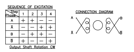
电机激励序列与绕组连接 — 英文原图,PDF 第 163 页
激励序列;输出轴顺时针(CW)旋转。
| 相位 / 步骤 | 1 | 2 | 3 | 4 |
|---|---|---|---|---|
| A | + | + | − | − |
| A̅ | − | − | + | + |
| B | − | + | + | − |
| B̅ | + | − | − | + |
1.3) 获取使能引脚。MP6507 需要 4 路 PWM 生成步进电机控制波形。由于硬件 PWM 有限,对焦、变焦和 P 光圈电机分别采用一颗 MP6507,通过 gpio 使能对应芯片,实现 PWM 分时复用。缺点是同一时间只能驱动一个步进电机,另外两个必须等待上一次操作结束。
1.4) 获取各电机的最大步数、最大启动速度、最大运行速度、加速曲线数据等硬件约束与资源。
2. hrtimer_init:初始化定时器。PWM 使用连续模式,需要定时;输出达到指定个数的 PWM 波形后,定时器中断关闭 PWM。加速过程也需在指定波形数后通过定时器中断修改 PWM 频率,从而实现步进电机加速。
3. init_completion:通过 completion 实现同步;前一次电机运动结束后才能执行下一次操作。
4. 初始化 v4l2 设备和媒体实体。
v4l2 子设备:v4l2_i2c_subdev_init。驱动要求 subdev 具有独立设备节点,供用户态 rkaiq 访问,并通过该节点控制电机;
媒体实体:media_entity_init;
5. 闪光灯设备名称:
  snprintf(sd->name, sizeof(sd->name), "m%02d_%s_%s",
           motor->module_index, facing,
           DRIVER_NAME);
2. 实现 v4l2 子设备驱动,主要实现以下两个成员:
  struct v4l2_subdev_core_ops
  struct v4l2_ctrl_ops
2.1 按照 v4l2_subdev_core_ops 的说明实现回调函数,主要包含以下回调:
  .ioctl
  .compat_ioctl32
此回调主要实现 RK 私有控制命令,包括:
| 成员名称 | 说明 |
|---|---|
| RK_VIDIOC_VCM_TIMEINFO | 对焦时间,用于判断当前帧是否为对焦后的有效帧。 |
| RK_VIDIOC_ZOOM_TIMEINFO | 变焦时间信息,用于判断当前帧是否为变焦完成后的有效帧。 |
| RK_VIDIOC_IRIS_TIMEINFO | 光圈时间信息,用于判断当前帧是否为光圈调整后的有效帧。 |
| RK_VIDIOC_FOCUS_CORRECTION | 对焦位置校正(复位) |
| RK_VIDIOC_ZOOM_CORRECTION | 变焦位置校正(复位) |
| RK_VIDIOC_IRIS_CORRECTION | 光圈位置校正(复位) |
2.2 按照 v4l2_ctrl_ops 的说明实现回调函数,主要包含以下回调:
.g_volatile_ctrl
.s_ctrl
.g_volatile_ctrl 和 .s_ctrl 使用标准 v4l2 control 实现以下命令:
| 参数名称 | 说明 |
|---|---|
| V4L2_CID_FOCUS_ABSOLUTE | 控制对焦;0 表示最小焦距,近处清晰。 |
| V4L2_CID_ZOOM_ABSOLUTE | 控制变焦倍数;0 表示最小倍数、最大视场。 |
| V4L2_CID_IRIS_ABSOLUTE | 控制 P 光圈开口;0 表示关闭(原文末尾含 **)。 |
3. 步进电机加速曲线参考:
3.1 梯形曲线:可如图按相等时间间隔和速度增量进行加减速。
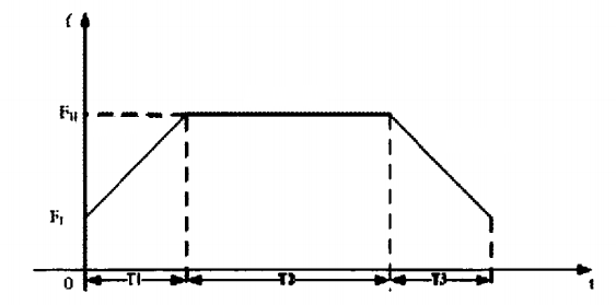
电机梯形加速曲线 — 英文原图,PDF 第 165 页
3.2 S 形曲线:若梯形加速不理想,可采用 S 形加速,参考公式:Speed = Vmin + ((Vmax-Vmin) / (1 + exp(-fac * (i-Num) / Num)));
其中:
Vmin 为电机起步速度,Vmax 为目标速度。fac 为曲线系数,通常取 4~6,越大则曲线中段越陡。i 为速度段编号,若分 32 段加速,取值 0~31。Num 为速度段数的一半,分 32 段时 num 为 16。
电机 S 型加速曲线 — 英文原图,PDF 第 165 页
13.2 MS41908 设备注册(DTS)
部分镜头支持 PIRIS、FOCUS、ZOOM、ZOOM1,或 DC-IRIS、FOCUS、ZOOM 的组合,因此 MS41908 将 PIRIS、FOCUS、ZOOM、ZOOM1、DC-IRIS 设计为可配置功能,并可多次加载驱动来组合多个驱动芯片。这使 dts 较复杂,请仔细阅读各参数说明。
  &spi0 {
      status = "okay";
      pinctrl-names = "default";
      pinctrl-0 = <&spi0m0_clk &spi0m0_cs0n &spi0m0_miso &spi0m0_mosi>;
      //If pinctrl is not configured, confirm whether the default pinctrl is the actual pin group
      assigned-clocks = <&pmucru CLK_SPI0>;
      assigned-clock-rates = <100000000>;
      ms41908: ms41908@00 {
          status = "okay";
          compatible = "relmon,ms41908";
          reg = <0>;
          pinctrl-names = "default";
          focus-start-up-speed = <800>;
          zoom-start-up-speed = <800>;
          focus-step-max = <3160>;
          zoom-step-max = <1520>;
          focus-backlash = <18>;
          vd_fz-period-us = <10000>;
          vd_fz-gpios = <&gpio3 RK_PC6 GPIO_ACTIVE_HIGH>;
          rockchip,camera-module-index = <1>;
          rockchip,camera-module-facing = "front";
          use-focus;
          use-zoom;
          focus-used-pin = "cd";
          zoom-used-pin = "ab";
      };
  };
  &i2c1 {
      imx335: imx335@1a{
          ...
          lens-focus = <&ms41908>;
          //Multiple device registration,lens-focus = <&ms41908_0 &ms41908_1>;
          ...
      };
  };
13.2.1 基本说明:
| 成员名称 | 说明 |
|---|---|
| pinctrl-0 | SPI 引脚定义,按硬件配置映射 SPI 功能,例如 pinctrl-0 = <&spi0m0_clk &spi0m0_cs0n &spi0m0_miso &spi0m0_mosi>;。 |
| assigned-clocks assigned-clock-rates | SPI 时钟配置,建议 100MHz。 |
| reg | reg = <0>; 使用 cs0;reg = <1>; 使用 cs1。 |
| rockchip,camera-module-index | 摄像头序号,用于匹配摄像头。 |
| rockchip,camera-module-facing | 摄像头朝向,用于匹配摄像头。 |
| reset-gpios | ms41908 复位引脚,硬件固定上拉时可不配置。 |
| vd_fz-period-us | 步进驱动寄存器更新所需脉冲周期,两电机共用同一脉冲。电机运行时间超过 vd 周期会失步,驱动保证单次运动周期在 vd 周期内。 |
13.2.2 FOCUS 说明:
| 成员名称 | 说明 |
|---|---|
| use-focus | 是否使用对焦功能 |
| focus-used-pin | 每颗 ms41908 可驱动两电机,对应引脚组为 ab、cd,按实际硬件接线配置。 |
| focus-backlash | 齿轮间隙造成的误差,电机换向时补偿的步数,由实际镜头测试确定。 |
| focus-start-up-speed | 步进电机起始速度,单位 PPS。 |
| focus-step-max | 电机有效行程,单位为步数。 |
| focus-ppw | 设置 ms41908 输出 PWM 占空比 0–255,值越大驱动能力越强,按电机负载调整。 |
| focus-phmode | 设置 ms41908 输出 PWM 波形相位校正,通常不配置,依实际情况确定。 |
| focus-micro | 微步细分为 64、128、256,默认 256。 |
| focus-reback-distance | 对焦曲线须沿同一方向运动才能定位准确。例如当前位置 100,要退到 90,须先退至 80 再到 90;此参数为额外回退步数。 |
| focus-1-2phase-excitation | 默认 2-2 相励磁,可配置 1-2 相,例如 focus-1-2phase-excitation;。 |
| focus-dir-opposite | 电机方向与实际对焦曲线相反时可反转,例如 focus-dir-opposite;。 |
光耦说明:
| 成员名称 | 说明 |
|---|---|
| focus-pic | 光耦 C 引脚检测电平跳变,跳变交界点为光耦原点。 |
| focus-pia | 光耦 A 引脚驱动光电二极管,校准时拉高、正常工作拉低,否则影响成像。 |
| focus-pie | 硬件可直接接地;若由 GPIO 控制,须配置为低电平。 |
| focus-min-pos | 测量光耦原点左右步数并填入 DTS,可大于实际值。 |
| focus-min-pos | 测量光耦原点左右步数并填入 DTS,可大于实际值。 |
注意:无光耦定位的镜头无需配置光耦参数。
13.2.3 ZOOM 说明:
| 成员名称 | 说明 |
|---|---|
| use-zoom | 是否使用变焦功能 |
| zoom-used-pin | 每颗 ms41908 可驱动两电机,对应引脚组为 ab、cd,按实际硬件接线配置。 |
| zoom-backlash | 齿轮间隙误差,电机换向补偿步数,按测试确定。 |
| zoom-start-up-speed | 步进电机起始速度,单位 PPS。 |
| zoom-step-max | 电机有效行程,单位为步数。 |
| zoom-ppw | 设置 ms41908 输出 PWM 占空比 0–255,值越大驱动能力越强,按电机负载调整。 |
| zoom-phmode | 设置 ms41908 输出 PWM 波形相位校正,通常不配置,依实际情况确定。 |
| zoom-micro | 微步细分为 64、128、256,默认 256。 |
| zoom-1-2phase-excitation | 默认 2-2 相励磁,可用 zoom-1-2phase-excitation; 配置 1-2 相。 |
| zoom-dir-opposite | 运动方向与实际对焦曲线相反时,用 zoom-dir-opposite; 反转。 |
光耦说明:
| 成员名称 | 说明 |
|---|---|
| zoom-pic | 光耦 C 引脚检测电平跳变,跳变交界点为光耦原点。 |
| zoom-min-pos | 测量光耦原点左右步数并填入 DTS,可大于实际值。 |
| zoom-min-pos | 测量光耦原点左右步数并填入 DTS,可大于实际值。 |
注意:无光耦定位的镜头无需配置光耦参数。
13.2.4 ZOOM1 说明:
| 成员名称 | 说明 |
|---|---|
| use-zoom1 | 是否启用 zoom1;部分镜头支持两组变焦控制。 |
| zoom1-used-pin | 每颗 ms41908 可驱动两电机,对应引脚组为 ab、cd,按实际硬件接线配置。 |
| zoom1-backlash | 齿轮间隙误差,电机换向补偿步数,按测试确定。 |
| zoom1-start-up-speed | 步进电机起始速度,单位 PPS。 |
| zoom1-step-max | 电机有效行程,单位为步数。 |
| zoom1-ppw | 设置 ms41908 输出 PWM 占空比 0–255,值越大驱动能力越强,按电机负载调整。 |
| zoom1-phmode | 设置 ms41908 输出 PWM 波形相位校正,通常不配置,依实际情况确定。 |
| zoom1-micro | 微步细分为 64、128、256,默认 256。 |
| zoom1-1-2phase-excitation | 默认 2-2 相励磁,可用 zoom1-1-2phase-excitation; 配置 1-2 相。 |
| zoom1-dir-opposite | 运动方向与实际对焦曲线相反时,用 zoom1-dir-opposite; 反转。 |
光耦说明:
| 成员名称 | 说明 |
|---|---|
| zoom1-pic | 光耦 C 引脚检测电平跳变,跳变交界点为光耦原点。 |
| zoom1-pia | 光耦 A 引脚驱动光电二极管,校准时拉高、正常工作拉低,否则影响成像。 |
| zoom1-pie | 硬件可直接接地;若由 GPIO 控制,须配置为低电平。 |
| zoom1-min-pos | 测量光耦原点左右步数并填入 DTS,可大于实际值。 |
| zoom1-min-pos | 测量光耦原点左右步数并填入 DTS,可大于实际值。 |
注意:无光耦定位的镜头无需配置光耦参数。
13.2.5 PIRIS 说明:
| 成员名称 | 说明 |
|---|---|
| use-p-iris | 是否使用 P-IRIS |
| piris-used-pin | 每颗 ms41908 可驱动两电机,对应引脚组为 ab、cd,按实际硬件接线配置。 |
| piris-backlash | 齿轮间隙造成的误差,电机换向时补偿的步数,由实际镜头测试确定。 |
| piris-start-up-speed | 步进电机起始速度,单位 PPS。 |
| piris-step-max | 电机有效行程,单位为步数。 |
| piris-ppw | 设置 ms41908 输出 PWM 占空比 0–255,值越大驱动能力越强,按电机负载调整。 |
| piris-phmode | 设置 ms41908 输出 PWM 波形相位校正,通常不配置,依实际情况确定。 |
| piris-micro | 微步细分为 64、128、256,默认 256。 |
| piris-1-2phase-excitation | 默认 2-2 相励磁,可用 piris-1-2phase-excitation; 配置 1-2 相。 |
| piris-dir-opposite | 运动方向与实际对焦曲线相反时,用 piris-dir-opposite; 反转。 |
光耦说明:
| 成员名称 | 说明 |
|---|---|
| piris-pic | 光耦 C 引脚检测电平跳变,跳变交界点为光耦原点。 |
| piris-pia | 光耦 A 引脚驱动光电二极管,校准时拉高、正常工作拉低,否则影响成像。 |
| piris-pie | 硬件可直接接地;若由 GPIO 控制,须配置为低电平。 |
| piris-min-pos | 测量光耦原点左右步数并填入 DTS,可大于实际值。 |
| piris-min-pos | 测量光耦原点左右步数并填入 DTS,可大于实际值。 |
注意:无光耦定位的镜头无需配置光耦参数。
13.2.6 DCIRIS 说明:
| 成员名称 | 说明 |
|---|---|
| use-dc-iris | 是否使用 DC-IRIS |
| vd_iris-gpios | 使 DC 光圈相关寄存器生效的同步脉冲引脚。 |
| dc-iris-reserved-polarity | DC 光圈极性;若 0 表示全开,可设置此属性反转。 |
| dc-iris-max-log | DC 光圈目标范围为 0~1023,实际有效范围可能更小,可用此参数限制。 |
13.2.7 数据类型简述
13.2.7.1 struct spi_driver
[说明]
定义 platform 设备驱动信息。
[定义]
  struct spi_driver {
          int (*probe)(struct spi_device *spi);
          int (*remove)(struct spi_device *spi);
          struct device_driver driver;
          const struct spi_device_id *id_table;
  };
[关键成员]
| 成员名称 | 说明 |
|---|---|
| @driver | struct device_driver 主要包含驱动名称及匹配 DTS 设备的 of_match_table;compatible 匹配时调用 .probe。 |
| @id_table | 内核不通过 of_match_table 与 DTS 注册设备匹配时,使用此表。 |
| @probe | 设备绑定回调 |
| @remove | 设备解绑回调 |
[示例]
  static const struct spi_device_id motor_match_id[] = {
      {"relmon,ms41908", 0 },
      { }
  };
  static struct spi_driver motor_dev_driver = {
      .driver = {
          .name = DRIVER_NAME,
          .of_match_table = of_match_ptr(motor_dev_of_match),
      },
      .probe      = &motor_dev_probe,
      .remove     = &motor_dev_remove,
      .id_table   = motor_match_id,
  };
13.2.7.2 struct v4l2_subdev_core_ops
[说明]
定义 subdev 的 core ops 回调。
[定义]
  struct v4l2_subdev_core_ops {
      ……
      long (*ioctl)(struct v4l2_subdev *sd, unsigned int cmd, void *arg);
  #ifdef CONFIG_COMPAT
      long (*compat_ioctl32)(struct v4l2_subdev *sd, unsigned int cmd,
               unsigned long arg);
  #endif
      ……
  };
[关键成员]
| 成员名称 | 说明 |
|---|---|
| .ioctl | 在 V4L2 core 的 ioctl() 系统调用处理末尾调用,支持驱动私有 ioctl。 |
| .compat_ioctl32 | 32 位程序使用 64 位内核时调用,以调整用户空间与内核间传递的数据。原文重复该说明。 |
[示例]
  static const struct v4l2_subdev_core_ops motor_core_ops = {
      .ioctl = motor_ioctl,
  };
  static const struct v4l2_subdev_ops motor_subdev_ops = {
      .core   = &motor_core_ops,
  };
13.2.7.3 struct v4l2_ctrl_ops
[说明]
驱动需要提供的 control 操作。
[定义]
  struct v4l2_ctrl_ops {
      int (*g_volatile_ctrl)(struct v4l2_ctrl *ctrl);
      int (*s_ctrl)(struct v4l2_ctrl *ctrl);
  };
[关键成员]
| 成员名称 | 说明 |
|---|---|
| .g_volatile_ctrl | 获取此 control 的新值,通常仅用于 volatile(一般为只读)的 control,例如返回持续变化的当前信号强度的 control。 |
| .s_ctrl | 实际设置 control 新值;s_ctrl 必须实现。调用持有 ctrl->handler->lock,其他访问者不能操作该 handler 的 controls。 |
[示例]
  static const struct v4l2_ctrl_ops motor_ctrl_ops = {
      .s_ctrl = motor_s_ctrl,
  };
13.2.8 API 简述
13.2.8.1 xxxx_set_ctrl
[说明]
调用标准 v4l2_control 设置对焦、变焦和 P 光圈位置。
驱动实现以下 v4l2 标准命令:
| 参数名称 | 说明 |
|---|---|
| V4L2_CID_FOCUS_ABSOLUTE | 控制对焦,0 为最小焦距,近处清晰。 |
| V4L2_CID_ZOOM_ABSOLUTE | 控制变焦倍数,0 为最小倍数和最大视角。 |
| V4L2_CID_IRIS_ABSOLUTE | 控制光圈开口,0 为关闭。 |
| V4L2_CID_ZOOM_CONTINUOUS | 控制 zoom1 倍数,用于多组变焦控制。 |
[语法]
static int xxxx_set_ctrl(struct v4l2_ctrl *ctrl)
[参数]
| 参数名称 | 说明 | 输入/输出 |
|---|---|---|
| *ctrl | v4l2 control 结构指针 | 输入 |
13.2.8.2 xxxx_ioctl xxxx_compat_ioctl
[说明]
自定义 ioctl 的实现主要包括获取对焦、变焦和 P 光圈的时间信息(运动开始与结束时间戳)。由于使用的镜头没有定位装置,必要时需重置镜头电机位置。
驱动实现的自定义命令:
| 参数名称 | 说明 |
|---|---|
| RK_VIDIOC_VCM_TIMEINFO | 对焦时间,用于判断当前帧是否为对焦后的有效帧。 |
| RK_VIDIOC_ZOOM_TIMEINFO | 变焦时间,用于判断当前帧是否为变焦完成后的有效帧。 |
| RK_VIDIOC_IRIS_TIMEINFO | 光圈时间,用于判断当前帧是否为 P 光圈调整后的有效帧。 |
| RK_VIDIOC_ZOOM1_TIMEINFO | 多变焦组时 zoom1 的时间,用于判断当前帧是否为变焦完成后的有效帧。 |
| RK_VIDIOC_IRIS_CORRECTION | 光圈位置复位,仅用于 P-IRIS。 |
| RK_VIDIOC_FOCUS_CORRECTION | 对焦位置复位 |
| RK_VIDIOC_ZOOM_CORRECTION | 变焦位置复位 |
| RK_VIDIOC_ZOOM1_CORRECTION | 双变焦镜头第二组变焦位置复位 |
| RK_VIDIOC_FOCUS_SET_POSITION | 设置对焦位置 |
| RK_VIDIOC_ZOOM_SET_POSITION | 设置跟焦参数,按变焦曲线实现多步变焦与对焦联动。 |
注意:
1. 为解决齿轮间隙导致电机绝对位置不准的问题,固定一个方向为正向、另一个为反向,使齿轮初始位置贴合正向。反向运动时需多走超过齿隙的 n 步,再正向走 n 步,使齿轮保持贴合正向,这称为回调。回调保证绝对位置精度,但步数大于齿隙,手动或自动对焦连续反向移动时,每次回调会产生抖动感,因此不能每次反向都回调。新增 RK_VIDIOC_FOCUS_SET_POSITION 和 RK_VIDIOC_ZOOM_SET_POSITION 由 AF 算法决定是否回调。标准命令 V4L2_CID_FOCUS_ABSOLUTE、V4L2_CID_ZOOM_ABSOLUTE 不回调,仅用于手动模式。RK_VIDIOC_ZOOM_SET_POSITION 同时包含 focus 和zoom 参数,在变焦时同步调整焦点,使画面过渡自然。
2. 早期通过配置 focus-backlash,在反向运动时额外走齿隙对应步数来补偿。但镜头齿隙存在个体差异,标定有误差且工作量大,因此此参数已弃用。驱动仍保留该设计,位置精度要求不高时仍可使用。
[语法]
  static int xxxx_ioctl(struct v4l2_subdev *sd, unsigned int cmd, void *arg)
  static long xxxx_compat_ioctl32(struct v4l2_subdev *sd, unsigned int cmd,
  unsigned long arg)
[参数]
| 参数名称 | 说明 | 输入/输出 |
|---|---|---|
| *sd | v4l2 subdev 结构指针 | 输入 |
| cmd | ioctl 命令 | 输入 |
| *arg/arg | 参数指针 | 输出 |
[返回值]
| 返回值 | 说明 |
|---|---|
| 0 | 成功 |
| 非 0 | 失败 |
13.2.9 驱动移植步骤
SPI 控制的驱动芯片可采用 SPI 框架移植,以 MS41908 为参考。参考驱动:/kernel/drivers/media/spi/ms41908.c。
移植步骤如下:
1. 实现标准 spi 子设备驱动部分。
1.1 根据 struct spi_driver 的说明,主要实现以下部分:
struct driver.name
struct driver. of_match_table
probe 函数
remove 函数
1.2 probe 函数实现详解:
1)获取设备资源,主要获取 DTS 资源,参见 MS41908 设备注册(DTS);
1.1) RK 私有资源采用 rockchip, camera-module-xxx 等命名,主要提供设备参数以匹配 Camera 设备。
1.2) 获取电机相关配置参数,依据芯片功能需求定义,尽量将电机运动相关参数设计为可配置。
2. hrtimer_init:初始化定时器。MS41908 以 VD 信号触发,定时器固定每个 VD 的周期以便操作。寄存器在 VD 信号后生效,每次修改可在 VD 之前提前配置。注意寄存器设置的速度和步数必须落在 VD 周期内,超出周期的步数会丢失。
3)init_completion 通过 completion 实现同步;同一电机必须在前一次操作结束后才能执行下一次操作。
4. 初始化 v4l2 设备和媒体实体。
v4l2 子设备:v4l2_i2c_subdev_init。驱动要求 subdev 具有独立设备节点,供用户态 rkaiq 访问,并通过该节点控制电机;
媒体实体:media_entity_init;
5. 设备名称:
  snprintf(sd->name, sizeof(sd->name), "m%02d_%s_%s",
           motor->module_index, facing,
           DRIVER_NAME);
2. 实现 v4l2 子设备驱动,主要实现以下 2 个成员:
  struct v4l2_subdev_core_ops
  struct v4l2_ctrl_ops
2.1 按 v4l2_subdev_core_ops 的说明实现回调函数,主要包含以下回调:
  .ioctl
  .compat_ioctl32
2.2 按 v4l2_ctrl_ops 的说明实现回调函数,主要包含以下回调:
.g_volatile_ctrl
.s_ctrl
14. DC-IRIS 驱动
与 P-IRIS 不同,DC-IRIS 无法精确获知光圈开度,通常默认全开。曝光已降至最小仍过曝,或升至最大仍欠曝时,才调整光圈。其直流电机通过霍尔器件负反馈缓冲调节速度,驱动用一路 PWM 控制即可。占空比小于 20% 时光圈逐渐关闭直至全闭,越小关闭越快;大于 40% 时逐渐打开,越大打开越快;20%~40% 保持不动。20%、40% 并非固定值,取决于 PWM 频率和实际器件精度。参考驱动:/kernel/drivers/media/i2c/hall-dc-motor.c。
14.1 DC-IRIS 设备注册(DTS)
  hal_dc_motor: hal_dc_motor{
          status = "okay";
          compatible = "rockchip,hall-dc";
          pwms = <&pwm6 0 2500 0>;
          rockchip,camera-module-index = <1>;
          rockchip,camera-module-facing = "front";
  };
  &pwm6 {
          status = "okay";
          pinctrl-names = "active";
          pinctrl-0 = <&pwm6m0_pins_pull_down>;
  };
  &i2c1 {
      imx334: imx334@1a {
          ...
          lens-focus = <&hal_dc_motor>;
          ...
      }
  }
14.1.1 数据类型简述
14.1.1.1 struct platform_driver
[说明]
定义 platform 设备驱动信息。
[定义]
  struct platform_driver {
          int (*probe)(struct platform_device *);
          int (*remove)(struct platform_device *);
          void (*shutdown)(struct platform_device *);
          int (*suspend)(struct platform_device *, pm_message_t state);
          int (*resume)(struct platform_device *);
          struct device_driver driver;
          const struct platform_device_id *id_table;
          bool prevent_deferred_probe;
  };
[关键成员]
| 成员名称 | 说明 |
|---|---|
| @driver | struct device_driver 主要包含驱动名称及匹配 DTS 设备的 of_match_table;compatible 匹配时调用 .probe。 |
| @id_table | 内核不通过 of_match_table 与 DTS 注册设备匹配时,使用此表。 |
| @probe | 设备绑定回调 |
| @remove | 设备解绑回调 |
[示例]
  #if defined(CONFIG_OF)
  static const struct of_device_id motor_dev_of_match[] = {
      { .compatible = "rockchip,hall-dc", },
      {},
  };
  #endif
  static struct platform_driver motor_dev_driver = {
      .driver = {
          .name = DRIVER_NAME,
          .owner = THIS_MODULE,
          .of_match_table = of_match_ptr(motor_dev_of_match),
      },
      .probe = motor_dev_probe,
      .remove = motor_dev_remove,
  };
  module_platform_driver(motor_dev_driver);
14.1.1.2 struct v4l2_subdev_core_ops
[说明]
定义 subdev 的 core ops 回调。
[定义]
  struct v4l2_subdev_core_ops {
      ……
      long (*ioctl)(struct v4l2_subdev *sd, unsigned int cmd, void *arg);
  #ifdef CONFIG_COMPAT
      long (*compat_ioctl32)(struct v4l2_subdev *sd, unsigned int cmd,
               unsigned long arg);
  #endif
      ……
  };
[关键成员]
| 成员名称 | 说明 |
|---|---|
| .ioctl | 在 V4L2 core 的 ioctl() 系统调用处理末尾调用,支持驱动私有 ioctl。 |
| .compat_ioctl32 | 32 位程序使用 64 位内核时调用,以调整用户空间与内核间传递的数据。原文重复该说明。 |
[示例]
  static const struct v4l2_subdev_core_ops motor_core_ops = {
      .ioctl = motor_ioctl,
  };
  static const struct v4l2_subdev_ops motor_subdev_ops = {
      .core   = &motor_core_ops,
  };
14.1.1.3 struct v4l2_ctrl_ops
[说明]
驱动需要提供的 control 操作。
[定义]
  struct v4l2_ctrl_ops {
      int (*s_ctrl)(struct v4l2_ctrl *ctrl);
  };
[关键成员]
| 成员名称 | 说明 |
|---|---|
| .s_ctrl | 实际设置 control 新值;s_ctrl 必须实现。调用持有 ctrl->handler->lock,其他访问者不能操作该 handler 的 controls。 |
[示例]
  static const struct v4l2_ctrl_ops motor_ctrl_ops = {
      .s_ctrl = motor_s_ctrl,
  };
14.1.2 API 简述
14.1.2.1 xxxx_set_ctrl
[说明]
调用标准 v4l2_control 设置光圈位置。实际上 DC 光圈无法获知具体位置,此处设置的是 pwm 占空比。
实现以下 v4l2 标准命令:
| 参数名称 | 说明 |
|---|---|
| V4L2_CID_IRIS_ABSOLUTE | 设置控制光圈的 PWM 占空比,范围 0~100。 |
[语法]
static int xxxx_set_ctrl(struct v4l2_ctrl *ctrl)
[参数]
| 参数名称 | 说明 | 输入/输出 |
|---|---|---|
| *ctrl | v4l2 control 结构指针 | 输入 |
[返回值]
| 返回值 | 说明 |
|---|---|
| 0 | 成功 |
| 非 0 | 失败 |
14.1.2.2 xxxx_ioctl xxxx_compat_ioctl
[说明]
目前无需实现私有定义;为满足 v4l2 框架注册要求实现空函数。
[语法]
  static int xxxx_ioctl(struct v4l2_subdev *sd, unsigned int cmd, void *arg)
  static long xxxx_compat_ioctl32(struct v4l2_subdev *sd, unsigned int cmd,
  unsigned long arg)
[参数]
| 参数名称 | 说明 | 输入/输出 |
|---|---|---|
| *sd | v4l2 subdev 结构指针 | 输入 |
| cmd | ioctl 命令 | 输入 |
| *arg/arg | 参数指针 | 输出 |
[返回值]
| 返回值 | 说明 |
|---|---|
| 0 | 成功 |
| 非 0 | 失败 |
14.1.3 驱动移植步骤
参考驱动:/kernel/drivers/media/i2c/hall-dc-motor.c。
移植步骤如下:
1. 实现标准 platform 子设备驱动部分。
1.1 根据 struct platform_driver 的说明,主要实现以下部分:
struct driver.name
struct driver. of_match_table
probe 函数
remove 函数
1.2 probe 函数实现详解:
1. 获取设备资源,主要为 DTS 资源,参见 DC-IRIS 设备注册(DTS)。
1.1) RK 私有资源采用 rockchip, camera-module-xxx 等命名,主要提供设备参数以匹配 Camera 设备。
1.2) 获取 pwm 资源,注意 pwm 节点是否已启用。
2. 初始化 v4l2 设备和媒体实体。
v4l2 子设备:v4l2_i2c_subdev_init。驱动要求 subdev 具有独立设备节点,供用户态 rkaiq 访问,并通过该节点控制电机;
媒体实体:media_entity_init;
3. 闪光灯设备名称:
  snprintf(sd->name, sizeof(sd->name), "m%02d_%s_%s",
           motor->module_index, facing,
           DRIVER_NAME);
2. 实现 v4l2 子设备驱动,主要实现以下两个成员:
  struct v4l2_subdev_core_ops
  struct v4l2_ctrl_ops
2.1 按照 v4l2_subdev_core_ops 的说明实现回调函数,主要包含以下回调:
  ioctl
  .compat_ioctl32
此回调目前不需实现具体命令,但作为 v4l2 子设备必须实现操作函数,因此此处实现空函数。
2.2 按照 v4l2_ctrl_ops 的说明实现回调函数,主要包含以下回调:
.g_volatile_ctrl.s_ctrl
.g_volatile_ctrl 和 .s_ctrl 使用标准 v4l2 control 实现以下命令:
| 成员名称 | 说明 |
|---|---|
| V4L2_CID_IRIS_ABSOLUTE | 设置控制光圈的 PWM 占空比,范围 0~100。 |
15. RK-IRCUT 驱动
IRCUT 由两根线控制,施加 3.5v~6v 电源。反转电源正负极并满足 100ms±10% 通电时间即可切换 IRCUT。驱动通过两个 gpio 控制电机驱动器电流输出方向,gpio 命令为 open(红线)和 close(黑线)。电流从 open 流向 close 时为红外截止滤光片,供白天使用;从 close 流向 open 时为白玻璃片,供夜间使用。
15.1 RK-IRCUT 设备注册(DTS)
  cam_ircut0: cam_ircut {
          status = "okay";
          compatible = "rockchip,ircut";
          ircut-open-gpios = <&gpio2 RK_PA7 GPIO_ACTIVE_HIGH>;
          ircut-close-gpios  = <&gpio2 RK_PA6 GPIO_ACTIVE_HIGH>;
          rockchip,camera-module-index = <1>;
          rockchip,camera-module-facing = "front";
  };
  &i2c1 {
      imx334: imx334@1a {
          ...
          ir-cut = <&cam_ircut0>;
          ...
      }
  }
15.1.1 数据类型简述
15.1.1.1 struct platform_driver
[说明]
定义 platform 设备驱动信息。
[定义]
  struct platform_driver {
          int (*probe)(struct platform_device *);
          int (*remove)(struct platform_device *);
          void (*shutdown)(struct platform_device *);
          int (*suspend)(struct platform_device *, pm_message_t state);
          int (*resume)(struct platform_device *);
          struct device_driver driver;
          const struct platform_device_id *id_table;
          bool prevent_deferred_probe;
  };
[关键成员]
| 成员名称 | 说明 |
|---|---|
| @driver | struct device_driver 主要包含驱动名称及匹配 DTS 设备的 of_match_table;compatible 匹配时调用 .probe。 |
| @id_table | 内核不通过 of_match_table 与 DTS 注册设备匹配时,使用此表。 |
| @probe | 设备绑定回调 |
| @remove | 设备解绑回调 |
[示例]
  #if defined(CONFIG_OF)
  static const struct of_device_id ircut_of_match[] = {
      { .compatible = "rockchip,ircut", },
      {},
  };
  #endif
  static struct platform_driver ircut_driver = {
      .driver = {
          .name = RK_IRCUT_NAME,
          .of_match_table = of_match_ptr(ircut_of_match),
      },
      .probe = ircut_probe,
      .remove = ircut_drv_remove,
  };
  module_platform_driver(ircut_driver);
15.1.1.2 struct v4l2_subdev_core_ops
[说明]
定义 subdev 的 core ops 回调。
[定义]
  struct v4l2_subdev_core_ops {
      ……
      long (*ioctl)(struct v4l2_subdev *sd, unsigned int cmd, void *arg);
  #ifdef CONFIG_COMPAT
      long (*compat_ioctl32)(struct v4l2_subdev *sd, unsigned int cmd,
               unsigned long arg);
  #endif
      ……
  };
[关键成员]
| 成员名称 | 说明 |
|---|---|
| .ioctl | 在 V4L2 core 的 ioctl() 系统调用处理末尾调用,支持驱动私有 ioctl。 |
| .compat_ioctl32 | 32 位程序使用 64 位内核时调用,以调整用户空间与内核间传递的数据。原文重复该说明。 |
[示例]
  static const struct v4l2_subdev_core_ops ircut_core_ops = {
      .ioctl = ircut_ioctl,
  };
  static const struct v4l2_subdev_ops ircut_subdev_ops = {
      .core   = &ircut_core_ops,
  };
15.1.1.3 struct v4l2_ctrl_ops
[说明]
驱动需要提供的 control 操作。
[定义]
  struct v4l2_ctrl_ops {
      int (*s_ctrl)(struct v4l2_ctrl *ctrl);
  };
[关键成员]
| 成员名称 | 说明 |
|---|---|
| .s_ctrl | 实际设置 control 新值;s_ctrl 必须实现。调用持有 ctrl->handler->lock,其他访问者不能操作该 handler 的 controls。 |
[示例]
  static const struct v4l2_ctrl_ops ircut_ctrl_ops = {
      .s_ctrl = ircut_s_ctrl,
  };
15.1.2 API 简述
15.1.2.1 xxxx_set_ctrl
[说明]
调用标准 v4l2_control 切换 IRCUT。
实现以下 v4l2 标准命令:
| 参数名称 | 说明 |
|---|---|
| V4L2_CID_BAND_STOP_FILTER | 0 为 CLOSE,红外光可进入;3 为 OPEN,红外光不能进入。 |
[语法]
static int xxxx_set_ctrl(struct v4l2_ctrl *ctrl)
[参数]
| 参数名称 | 说明 | 输入/输出 |
|---|---|---|
| *ctrl | v4l2 control 结构指针 | 输入 |
[返回值]
| 返回值 | 说明 |
|---|---|
| 0 | 成功 |
| 非 0 | 失败 |
15.1.2.2 xxxx_ioctl xxxx_compat_ioctl
[说明]
目前无需实现私有定义;为满足 v4l2 框架注册要求实现空函数。
[语法]
  static int xxxx_ioctl(struct v4l2_subdev *sd, unsigned int cmd, void *arg)
  static long xxxx_compat_ioctl32(struct v4l2_subdev *sd, unsigned int cmd,
  unsigned long arg)
[参数]
| 参数名称 | 说明 | 输入/输出 |
|---|---|---|
| *sd | v4l2 subdev 结构指针 | 输入 |
| cmd | ioctl 命令 | 输入 |
| *arg/arg | 参数指针 | 输出 |
[返回值]
| 返回值 | 说明 |
|---|---|
| 0 | 成功 |
| 非 0 | 失败 |
15.1.3 驱动移植步骤
参考驱动:/kernel/drivers/media/i2c/rk_ircut.c。
移植步骤如下:
1. 实现标准 platform 子设备驱动部分。
1.1 根据 struct platform_driver 的说明,主要实现以下部分:
struct driver.name
struct driver. of_match_table
probe 函数
remove 函数
1.2 probe 函数实现详解:
1. 获取设备资源,主要为 DTS 资源,参见 RK-IRCUT 设备注册(DTS)。
1.1) RK 私有资源采用 rockchip, camera-module-xxx 等命名,主要提供设备参数以匹配 Camera 设备。
1.2) 获取 open 和 close gpio 资源;
2. init_completion:利用 completion 同步。由于 IRCUT 切换约需 100ms,必须确保上一次切换完成后才能再次操作。
3. 创建工作队列,将切换操作放入队列,避免长时间阻塞。
4. 初始化 v4l2 设备和媒体实体。
v4l2 子设备:v4l2_i2c_subdev_init。驱动要求 subdev 具有独立设备节点,供用户态 rkaiq 访问,并通过该节点控制 IRCUT;
媒体实体:media_entity_init;
  sd->entity.function = MEDIA_ENT_F_LENS;
  sd->entity.flags = 1;//flag is fixed to 1, used to distinguish other sub-devices of MEDIA_ENT_F_LENS type
5. 设备名称:
  snprintf(sd->name, sizeof(sd->name), "m%02d_%s_%s",
           ircut->module_index, facing,
           RK_IRCUT_NAME);
2. 实现 v4l2 子设备驱动,主要实现以下两个成员:
  struct v4l2_subdev_core_ops
  struct v4l2_ctrl_ops
2.1 按照 v4l2_subdev_core_ops 的说明实现回调函数,主要包含以下回调:
  .ioctl
  .compat_ioctl32
此回调目前无需实现私有命令,但 v4l2 框架注册需要它,因此实现空函数,后续可按需补充函数内容。
2.2 按照 v4l2_ctrl_ops 的说明实现回调函数,主要包含以下回调:
.s_ctrl
.s_ctrl 使用标准 v4l2 control 实现以下命令:
| 成员名称 | 说明 |
|---|---|
| V4L2_CID_BAND_STOP_FILTER | 0 为 CLOSE,红外光可进入;3 为 OPEN,红外光不能进入。 |
16. media-ctl 与 v4l2-ctl 工具
media-ctl 通过 /dev/medio0 等 media 设备操作,管理 Media 拓扑中各节点的格式、尺寸和连接。(原稿写作 /dev/medio0,疑为 /dev/media0,保留原始信息待核对。)
v4l2-ctl 面向 /dev/video0、/dev/video1 等视频设备,执行 set_fmt、reqbuf、qbuf、dqbuf、stream_on、stream_off 等操作。
具体用法参见命令帮助,以下列出常用方式。
1. 打印拓扑
media-ctl -p -d /dev/media0
注意:isp2 设备节点较多,可能存在 media0/media1/media2,需逐一枚举检查设备信息。
2. 连接
  media-ctl -l'"rkisp-isp-subdev":2->"rkisp-bridge-ispp":0[0]'
  media-ctl -l'"rkisp-isp-subdev":2->"rkisp_mainpath":0[1]'
注意:断开 ISPP 路径并连接 main_path,从 main_path 抓取 RAW。media-ctl 不加 -d 时默认 /dev/media0;需确认 rkisp-isp-subdev 实际挂在哪个设备节点,通常是 /dev/media1。
3. 修改 fmt/size
  media-ctl -d /dev/media0 \
  --set-v4l2'"ov5695 7-0036":0[fmt:SBGGR10_1X10/640x480]'
注意:需确认摄像头设备节点(ov5695 7-0036)属于哪个 media 设备。
4. 设置 fmt 并抓帧
  v4l2-ctl -d /dev/video0 \
  --set-fmt-video=width=720,height=480,pixelformat=NV12 \
  --stream-mmap=3 \
  --stream-skip=3 \
  --stream-to=/tmp/cif.out \
  --stream-count=1 \
  --stream-poll
5. 设置曝光、增益等 controls
v4l2-ctl -d /dev/video3 --set-ctrl'exposure=1216,analogue_gain=10'
ISP 驱动会调用摄像头子设备控制命令,因此指定 video3(main_path/self_path)可设置曝光;VICAP 不调用这些命令,直接对采集节点设置会失败。应找到摄像头 /dev/v4l-subdevX,直接配置此终端节点。
17. RV1109/RV1126 内存优化指南
MIPI -> DDR_1 -> ISP -> DDR_2 -> ISPP(TNR) -> DDR_3 -> ISPP(NR&Sharp) -> DDR_4 -> ISPP(FEC) -> DDR_5
1. DDR_1:VICAP RAW 或 ISP MIPI RAW 数据写入 DDR,ISP 从DDR 读取 RAW 进行处理。
占用内存:buf_cnt * buf_size * N,其中 N = 1 为线性模式,2 为 hdr2 帧模式,3 为 hdr3 帧模式。
buf_size: ALIGN(width * bpp / 8, 256) * height;,bpp 为位宽,即 raw8、raw10 或 raw12。
buf_cnt:默认为 4,在 aiq 库代码 hwi/isp20/CamHwIsp20.h 中定义,最小为 3。
#define ISP_TX_BUF_NUM 4
#define VIPCAP_TX_BUF_NUM 4
为 VICAP 设备配置 ROCKCHIP_CIF_USE_NONE_DUMMY_BUF,减少一个内部 buffer。
2. DDR_2:ISP FBC YUV420 和 gain 数据写入 DDR,ISPP 读取处理。
占用内存:buf_size * buf_cnt。
buf_size: ALIGN(width, 64) * ALIGN(height, 128) / 16 + ALIGN(width, 16) * ALIGN(hieght, 16) * 1.5625
buf_cnt:tnr 3to1 模式使用 4 个 buf,2to1 模式使用 3 个;模式在 iq xml 中配置。
开启 motion 功能时提供一路缩放输出,mxn 降采样支持 IQ XML 配置为 4x8 和 8x8。
buf_size:ALIGN(width / m, 16) * (height / n) * 1.5
buf_cnt:默认 6,取决于 AIQ self_path video 请求的 buffer 数。
3. DDR_3:ISPP TNR FBC YUV420 和 gain 数据写入 DDR,ISPP NR&Sharp 再次从 DDR 读取处理。
占用内存:buf_size * buf_cnt。
buf_size: ALIGN(width, 64) * ALIGN(height, 128) / 16 + ALIGN(width, 16) * ALIGN(hieght, 16) * 1.5625
buf_cnt:2,为最小值。
4. DDR_4:ISPP NR&Sharp YUYV 数据写入 DDR,ISPP FEC 读取处理。
占用内存:buf_size * buf_cnt(未开启 fec 功能时不占用内存)。
buf_size: width * height * 2
buf_cnt:2,为最小值。
5. DDR_5:ISPP 四路输出图像 buffer,其大小由用户设置的分辨率、格式和 buf_cnt 计算。
上述 buf_cnt 是可进行内存优化配置的位置。
isp cma 预留内存大小:可先配置较大的内存,运行 camera app 后获取实际使用量。
  isp_reserved: isp {
      compatible = "shared-dma-pool";
      inactive;
      reusable;
      size = <0x10000000>;//256M and need 4M align
  };
  enable cma debug
  +++ b/arch/arm/configs/rv1126_defconfig
  @@ -62,6 +62,8 @@ CONFIG_IOSCHED_BFQ=y
   CONFIG_KSM=y
   CONFIG_DEFAULT_MMAP_MIN_ADDR=32768
   CONFIG_CMA=y
  +CONFIG_CMA_DEBUG=y
  +CONFIG_CMA_DEBUGFS=y
  one page is 4K, 26091 page is 104364K and need 4M align, so config 104M to
  isp_reserved
  [root@RV1126_RV1109:/sys/kernel/debug/cma/cma-isp@0]# ls
  alloc  base_pfn  bitmap  count free  maxchunk order_per_bit  used
  [root@RV1126_RV1109:/sys/kernel/debug/cma/cma-isp@0]# cat used
  26091
18. RV1109/RV1126 延迟优化指南
1、配置 vicap wait-line
在 dts 的 vicap 节点配置 wait-line。例如高度为 1520,wait-line 为 760,采集半幅图像后即提前将缓冲区输出给 isp。根据 isp 读取缓冲区的速度调整 wait-line。
&rkcif_mipi_lvds {
wait-line = <760>;
};
也可使用以下命令配置,支持动态配置。
echo 1000 > /sys/devices/platform/rkcif_mipi_lvds/wait_line
注意:wait-line 过小会导致 isp 过早访问缓冲内存,此时部分数据尚未采集,未更新部分仍是上一帧。画面剧烈变化时,图像尾部可能异常、呈现分裂。需依据实际测试选择合适的 wait-line。
2、配置 isp wait-line
在 dts 的 isp 节点配置 wait-line。例如高度为 1520,wait-line 为 760,处理到第 760 行时即输出给 ispp。根据 ISP 与 ISPP 的处理时间调整 wait-line。
&rkisp_vir0 {
wait-line = <760>;
};
也可通过 /sys/module/video_rkisp/parameters/wait_line 调试,须在打开 isp video 之前配置。
注意:wait-line 过小且 ISPP 快于 ISP 时,由于使用 FBC 压缩格式,会发生 hold 情况。Motion 功能和多传感器不支持此方式。
3、配置 ispp 四路输出的 wait-line
在 dts 的 ispp 节点配置 wait-line。例如高度为 1520,wait-line 为 896,处理至第 896 行时即输出给后端。根据 ISPP(nr 或 fec)与后端的处理时间调整 wait-line。
&rkispp_vir0 {
     status = "okay";
     wait-line = <896>;
};
也可通过 /sys/module/video_rkispp/parameters/wait_line 调试,须在打开 ispp video 之前配置。
注意:wait-line 配置过小且后端处理速度快于 ISPP 时,后端图像处理会异常。不支持多传感器。
4、提高硬件处理速度
1)提高 isp/ispp clk
drivers/media/platform/rockchip/isp/hw.c
static const struct isp_clk_info rv1126_isp_clk_rate[] = {
{
.clk_rate = 20,
.refer_data = 0,
}, {
.clk_rate = 600,
.refer_data = 1920, //width
}, {
.clk_rate = 600,
.refer_data = 2688,
}, {
.clk_rate = 600,
.refer_data = 3072,
}, {
.clk_rate = 600,
.refer_data = 3840,
}
};
drivers/media/platform/rockchip/ispp/hw.c
static const struct ispp_clk_info rv1126_ispp_clk_rate[] = {
{
.clk_rate = 150,
.refer_data = 0,
}, {
.clk_rate = 500,
.refer_data = 1920 //width
}, {
.clk_rate = 500,
.refer_data = 2688,
}, {
.clk_rate = 500,
.refer_data = 3072,
}, {
.clk_rate = 500,
.refer_data = 3840,
}
};
2)禁用 iommu,使用预留内存
&rkisp_mmu {
status = "disabled";
};
  &rkisp {
        memory-region = <&isp_reserved>;
  };
&rkispp_mmu {
status = "disabled";   };
  &rkispp {
        memory-region = <&isp_reserved>;
  };
19. 常见问题
19.1 如何单独更新驱动版本
(1) 从新 SDK 内核生成补丁。
git format-patch A..B drivers/media/common drivers/media/v4l2-core drivers/media/platform/rockchip drivers/media/i2c include/uapi/linux/rkisp2-config.h include/uapi/linux/rkisp21-config.h include/uapi/linux/rkispp-config.h include/uapi/linux/rkcif-config.h include/uapi/linux/rk-camera-module.h include/uapi/linux/rk_vcm_head.h include/uapi/linux/videodev2.h include/uapi/linux/media-bus-format.h -o tmp_patch
(2) 将补丁应用到旧 SDK 内核。
git am tmp_patch/*
注意:A 为旧内核 commit id,B 为新内核 commit id,tmp_patch 为补丁输出目录。
19.2 如何获取驱动版本号
从内核启动日志获取
  rkisp ffb50000.rkisp: rkisp driver version: v00.01.00
  rkispp ffb60000.rkispp: rkispp driver version: v00.01.00
通过以下方式获取
  cat /sys/module/video_rkisp/parameters/version
  cat /sys/module/video_rkispp/parameters/version
19.3 如何判断 RKISP 驱动加载状态
RKISP 驱动成功加载后,/dev/ 下会存在 video 和 media 设备。系统可能有多个 /dev/video,可通过 /sys 查询 RKISP 注册的视频节点。
localhost ~ # grep'' /sys/class/video4linux/video*/name
也可用 media-ctl 打印拓扑,检查 pipeline 是否正常。
判断摄像头驱动是否成功加载:所有摄像头注册完成时,内核会打印以下日志。
  localhost ~ # dmesg | grep Async
  [0.682982] RKISP: Async subdev notifier completed
若内核中没有 Async subdev notifier completed 这一行日志,先检查传感器是否报错、I2C 通信是否成功。
19.4 如何配置 ISP/VICAP RAW 存储格式
isp:
rv1109/rv1126:
三种模式:
0: raw12/raw10/raw8 8bit 紧凑存储
1: raw12/raw10 16bit 每像素占一个存储单元 大端
|15|14|13|12|11|10| 9| 8| 7| 6| 5| 4| 3| 2| 1| 0|
| 3| 2| 1| 0| -| -| -| -|11|10| 9| 8| 7| 6| 5| 4|
2: raw12/raw10 16bit 每像素占一个存储单元 高位对齐
|15|14|13|12|11|10| 9| 8| 7| 6| 5| 4| 3| 2| 1| 0|
|11|10| 9| 8| 7| 6| 5| 4| 3| 2| 1| 0| -| -| -| -|
rk356x:
三种模式:
0: raw12/raw10/raw8 8bit 紧凑存储
1: raw12/raw10 16bit 每像素占一个存储单元 低位对齐
|15|14|13|12|11|10| 9| 8| 7| 6| 5| 4| 3| 2| 1| 0|
| -| -| -| -|11|10| 9| 8| 7| 6| 5| 4| 3| 2| 1| 0|
2: raw12/raw10 16bit 每像素占一个存储单元 高位对齐
|15|14|13|12|11|10| 9| 8| 7| 6| 5| 4| 3| 2| 1| 0|
|11|10| 9| 8| 7| 6| 5| 4| 3| 2| 1| 0| -| -| -| -|
控制说明:
AIQ 增加了存储模式控制,启动 AIQ 程序时,会根据传感器型号配置支持的存储模式。
rv1109/rv1126:支持 AIQ v0x1.0x71.1 及以上版本;rk356x:支持 AIQ v2.60.01 及以上版本。
用户也可对流设备执行 ioctl 控制存储格式,相关定义见 include/uapi/linux/rkisp2-config.h:
  #define RKISP_CMD_GET_CSI_MEMORY_MODE \
      _IOR('V', BASE_VIDIOC_PRIVATE + 100, int)
  #define RKISP_CMD_SET_CSI_MEMORY_MODE \
      _IOW('V', BASE_VIDIOC_PRIVATE + 101, int)
  enum isp_csi_memory {
      CSI_MEM_COMPACT = 0,
      CSI_MEM_WORD_BIG_END = 1,
      CSI_MEM_WORD_LITTLE_ALIGN = 1,
      CSI_MEM_WORD_BIG_ALIGN = 2,
  };
vicap:
rv1109/rv1126/rk356x:
三种模式:
0: raw12/raw10/raw8 8bit 紧凑存储
1: raw12/raw10 16bit 每像素占一个存储单元 低位对齐,适用于 rv1126/rv1109/rk356x
|15|14|13|12|11|10| 9| 8| 7| 6| 5| 4| 3| 2| 1| 0|
| -| -| -| -|11|10| 9| 8| 7| 6| 5| 4| 3| 2| 1| 0|
2: raw12/raw10 16bit 每像素占一个存储单元 高位对齐,适用于 rv1126/rv1109/rk356x
|15|14|13|12|11|10| 9| 8| 7| 6| 5| 4| 3| 2| 1| 0|
|11|10| 9| 8| 7| 6| 5| 4| 3| 2| 1| 0| -| -| -| -|
注意:rv1109/rv1126/rk356x 的 DVP 仅支持非紧凑模式,可设置低位或高位对齐。
控制说明:
AIQ 增加了存储模式控制,启动 AIQ 程序时,会根据传感器型号配置支持的存储模式。
rv1109/rv1126:支持 AIQ v0x1.0x71.1 及以上版本;rk356x:支持 AIQ v2.60.01 及以上版本。
用户也可对流设备执行 ioctl 控制存储格式,相关定义见 include/uapi/linux/rkcif-config.h:
  #define RKCIF_CMD_GET_CSI_MEMORY_MODE \
      _IOR('V', BASE_VIDIOC_PRIVATE + 0, int)
  #define RKCIF_CMD_SET_CSI_MEMORY_MODE \
      _IOW('V', BASE_VIDIOC_PRIVATE + 1, int)
  enum cif_csi_lvds_memory {
      CSI_LVDS_MEM_COMPACT = 0,
      CSI_LVDS_MEM_WORD_LOW_ALIGN = 1,
      CSI_LVDS_MEM_WORD_HIGH_ALIGN = 2,
  };
对于 VICAP,可通过以下命令配置,但仅用于调试。
配置为非紧凑模式,每个数字对应一个通道。
echo 0 0 0 0 > /sys/devices/platform/rkcif_mipi_lvds/compact_test
配置为低位对齐。
echo 0 0 0 0 > /sys/devices/platform/rkcif_mipi_lvds/is_high_align
配置为高位对齐。
echo 0 0 0 0 > /sys/devices/platform/rkcif_mipi_lvds/is_high_align
19.5 如何配置 VICAP 异常复位
VICAP 驱动具有复位机制,在 VICAP 出现异常时通过 CRU 对其复位。具体用法如下:
kernel-4.19 的配置方法如下:
启用复位机制需要在 DTS 的 CIF 相关接口设备节点添加 rockchip、cif-monitor 参数;若 DTS 未设置此参数,默认不启用复位机制。
  &rkcif_mipi_lvds {
      status = "okay";
      /* rockchip,cif-monitor = <index0 index1 index2 index3 index4>; */
      rockchip,cif-monitor = <2 2 5 1000 5>;
      port {
          /* MIPI CSI-2 endpoint */
          cif_mipi_in: endpoint {
              remote-endpoint = <&mipi_csi2_output>;
              data-lanes = <1 2 3 4>;
          };
      };
  };
index0:描述复位模式,目前主要有四种,状态如下:
| 模式 | 说明 |
|---|---|
| Idle | 不使用监控。 |
| Continue | 实时连续监控 VICAP 是否发生 MIPI 错误和断流;出现错误或断流时执行 VICAP 复位。到达 index1 设置的帧数时,在帧结束中断初始化监控定时器,然后开始监控。原文随后称到达对应帧数时监控不能触发,语义有矛盾,需核对驱动。定时器按 index2 设置的周期采样检测。 |
| Trigger | 仅在 VICAP 出现 CSI2 协议层 MIPI 错误时触发复位。index4 设置 MIPI 错误报告次数;达到 index4 次时,在帧结束中断初始化监控定时器,经过 index2 设置的周期后执行 VICAP 复位。 |
| Hotplug | 热插拔模式主要用于 n4/tp6188 等车机转接芯片,解决插拔时画面破碎或断流问题。该模式包含 Continue 模式功能:持续监控 VICAP MIPI 错误和断流,出现时复位 VICAP;达到 index1 帧数时在帧结束中断初始化监控定时器并开始监控,未达到对应帧数则不能触发。定时器按 index2 周期采样检测。与 Continue 不同:即便 MIPI 无错误且未断流,若 VICAP 采集的 sensor 通过 RKMODULE_SET_VICAP_RST_INFO 命令设置并使能复位信息,VICAP 经 RKMODULE_GET_VICAP_RST_INFO 获取该信息后也会触发复位。 |
index1:对于 continue 或 hotplug,采集 index1 帧后启动监控定时器。
index2:监控定时器周期,以帧为单位,监控周期为 index2 帧。
index3:延迟复位时间参数。发现 VICAP CSI2 错误后,在规定时间内继续监控;错误不再增加时执行复位。超过规定时间后,无论错误是否继续增加,都立即执行复位。时间单位为 ms。
index4:设置 MIPI CSI 错误出现次数,达到此次数后触发复位。
为了同时支持 MIPI 和 DVP 异常检测,异常检测机制已修改,需要更新并包含以下提交:
  media: rockchip: rkcif reset all dev when trigger reset event
      move monitor param to rkcif node
      ag &rkcif {
          status = "okay";
          rockchip,cif-monitor = <3 200 1000 5 0>;
          /*
           * index 0: monitor mode
           *     val: 0 idle
           *          1 Continue mode, detect cut of stream or csi2 err
           *          2 trigger mode, detect csi2 err
           *          3 Hotplug, detect hot plug or cut off stream or csi2 err
           * index 1: monitor cycle
           *     val: timer of monitor cycle, unit ms
           * index 2: error interval
           *     val: time of error keeping, such as 1000,
           *          mean atfer one second error still occur,force reset dev,
           *          the max timer to wait error stop
           * index 3: err_ref_cnt:
           *     val: timer error ref val for reset
           * index 4: reset_by_user
           *     val: set val 1 to control reset by user
           */
      };
      Signed-off-by: Zefa Chen <zefa.chen@rock-chips.com>
      Change-Id: If4da872c7ee3c5140f94e5cf331cab84005361d2
详情:(1) 将原文所写的 “rockchip, cif monitor” 配置从 rkcif_ mipi_lvds 移至 rkcif 节点。(2) 删除 index1,改为启动流后开始检测。(3) 增加 reset_by_user 参数,设为 1 时驱动不主动复位,而是等待应用执行。应用定期轮询 video 节点的 ioctl “RKCIF_CMD_ET_RESET_INFO” 获取复位状态;状态为 1 表示需要复位。应用可在合适时机调用 ioctl “RKCIF_CMD_SET_RESET” 执行复位。(标识符按原稿保留,实际拼写须核对目标 BSP。)
kernel-5.10 的配置方法如下:
drivers/media/rockchip/cif/Kconfig 新增异常检测配置,可直接修改默认值,也可在 defconfig 中添加配置覆盖默认值。具体参数如下:
| ROCKCHIP_CIF_USE_MONITOR | 是否启用异常监控机制;需由客户启用,默认关闭。 |
|---|---|
| ROCKCHIP_CIF_MONITOR_MODE | 异常监控模式,定义与 kernel 4.19 一致。 |
| ROCKCHIP_CIF_MONITOR_START_FRAME | 从第几帧开始检测,建议配置为 0。 |
| ROCKCHIP_CIF_MONITOR_CYCLE | 检测周期,以帧间隔为单位。帧率为 25fps、配置为 4 时,周期为 40ms * 4。根据项目评估,建议检测周期约为 400ms。 |
| ROCKCHIP_CIF_MONITOR_KEEP_TIME | 延迟复位时间参数。发现 VICAP CSI2 错误后,在设定时间内持续监控;检测到错误不再增加时复位。超过设定时间后,无论错误是否继续增加,都立即复位。单位为 ms。 |
| ROCKCHIP_CIF_MONITOR_ERR_CNT | 通常指 MIPI 错误统计次数,默认配置 5,表示累计 5 * 2 次错误后触发复位。 |
| ROCKCHIP_CIF_RESET_BY_USER | 配置为 1 时仅检测异常,不主动复位,而是通知应用在适当时刻复位。 |
如果由用户控制复位,需注意两点:(1) 复位事件通过 MIPI CSI2 节点传递。通过 media-ctl -p -d /dev/mediaX(X 为 0、1、2、3 等)找到对应节点并监听复位事件。(2) 打开 video 节点,可任选 stream_cif_mipi_id0~3;这些节点属于同一硬件,通常选择 stream_cif_mipi_id0,通过复位 ioctl 执行复位。
示例:
  #include <stdio.h>
  #include <stdlib.h>
  #include <getopt.h>
  #include <fcntl.h>
  #include <unistd.h>
  #include <sys/ioctl.h>
  #include <linux/videodev2.h>
  #include "rkcif-config.h"
  int subscribe_event(int fd, int event)
  {
      int ret = 0;
      struct v4l2_event_subscription sub;
      if (fd < 0) {
          printf("fd is err\n");
          return -1;
      }
      sub.type = event;
      sub.id = 0;
      ret = ioctl(fd, VIDIOC_SUBSCRIBE_EVENT, &sub);
      if (ret < 0) {
          printf("VIDIOC_SUBSCRIBE_EVENT fail\n");
          return -1;
      }
      return 0;
  }
  int unsubscribe_event(int fd, int event)
  {
      int ret = 0;
      struct v4l2_event_subscription sub;
      if (fd < 0) {
          printf("fd is err\n");
          return -1;
      }
      sub.type = event;
      sub.id = 0;
      ret = ioctl(fd, VIDIOC_UNSUBSCRIBE_EVENT, &sub);
      if (ret < 0) {
          printf("VIDIOC_SUBSCRIBE_EVENT fail\n");
          return -1;
      }
      return 0;
  }
  int main(int argc, char **argv)
  {
      char *dev;
      int ret;
      int fd = -1;
      int fd_cif = -1;
      int i = 0;
      struct v4l2_event event;
      char *dev_cif;
      if (argc != 3) {
          printf("invalid input\n");
          for (i = 0; i < argc; i++)
              printf("argv[%d]:%s\n", i, argv[i]);
          return -1;
      }
      dev = argv[1];
      fd = open(dev, O_RDWR, 0);
      if (fd < 0) {
          printf("open dev:%s fail\n", dev);
          return -1;
      }
      dev_cif = argv[2];
      fd_cif = open(dev_cif, O_RDWR, 0);
      if (fd_cif < 0) {
          printf("open dev:%s fail\n", dev_cif);
          return -1;
      }
      ret = subscribe_event(fd, V4L2_EVENT_RESET_DEV);
      if (ret < 0)
          goto end;
      while (1) {
              printf("VIDIOC_DQEVENT ready %d\n", ret);
          ret = ioctl(fd, VIDIOC_DQEVENT, &event);
              if (ret) {
                      printf("VIDIOC_DQEVENT err %d\n", ret);
                      goto end;
                 }
          printf("VIDIOC_DQEVENT event %x, %d\n", event.type, event.reserved[0]);
          if (event.type == V4L2_EVENT_RESET_DEV) {
              ret = ioctl(fd_cif, RKCIF_CMD_SET_RESET, &event.reserved[0]);
              if (ret) {
                          printf("RKCIF_CMD_SET_RESET err %d\n", ret);
                          goto end;
              }
                 }
      }
  end:
      ret = unsubscribe_event(fd, V4L2_EVENT_RESET_DEV);
      close(fd);
      close(fd_cif);
      return 0;
  }
19.6 如何抓取 CIS 输出的 RAW 和 YUV 数据
驱动开发完成后,可直接使用标准 v4l2-ctl 命令操作驱动,获取 CIS 输出数据。可参考 v4l2-ctl 使用帮助:https://www.mankier.com/1/v4l2-ctl
示例:
v4l2-ctl -d /dev/video0 --set-fmt-video=width=1920,height=1080,pixelformat=RG10 --stream-mmap=4 --stream-count=1 --stream-to=/tmp/cap.raw --stream-skip=2
-d:指定设备名称。
–set-fmt-video:设置分辨率,必须与传感器输出一致。可通过 media-ctl -p -d /dev/mediaX 查看传感器当前分辨率。
pixelformat:输出数据格式,如 BG12、NV12。
–stream-mmap:mmap 缓冲区数量。
–stream-count:抓取帧数,多帧也存入同一文件。
–stream-to:指定存储路径。
–stream-skip:跳过的帧数。
19.6.1 设备支持列表
19.6.1.1 RV1109/RV1126
| 设备 | 接口 | 格式 | 设备节点名称 | 输出 Raw | 输出 YUV |
|---|---|---|---|---|---|
| VICAP | DVP | RAW | video0~video3 | 非紧凑 Raw | 无 |
| VICAP | MIPI/LVDS | RAW | video0~video3 | 非紧凑 Raw;紧凑 Raw | 无 |
| VICAP | DVP / MIPI / LVDS |
YUV | video0~video3 | 无 | nv12 nv16 |
| ISP | DVP / MIPI / LVDS |
RAW | rkisp_rawwr0 rkisp_rawwr1 rkisp_rawwr2 rkisp_rawwr3 |
非紧凑 Raw;紧凑 Raw | 无 |
| ISP | MIPI / LVDS | YUV | rkisp_mainpath | 非紧凑 Raw | nv12 nv16 |
| ISPP | 仅从 DDR 读取 | YUV | rkispp_m_bypass rkispp_scale0 rkispp_scale1 rkispp_scale2 |
无 | nv12 nv16 |
19.6.1.2 RK356X
| 设备 | 接口 | 格式 | 设备节点名称 | 输出 Raw | 输出 YUV |
|---|---|---|---|---|---|
| VICAP | DVP | RAW | video0~video3 | 非紧凑 Raw | 无 |
| VICAP | MIPI/LVDS | RAW | video0~video3 | 非紧凑 Raw;紧凑 Raw | 无 |
| VICAP | DVP / MIPI / LVDS |
YUV | video0~video3 | 无 | nv12 nv16 |
| ISP | DVP / MIPI / LVDS |
RAW | rkisp_rawwr0 rkisp_rawwr1 rkisp_rawwr2 rkisp_rawwr3 |
非紧凑 Raw;紧凑 Raw | 无 |
| ISP | MIPI / LVDS | YUV | rkisp_mainpath | 非紧凑 Raw | nv12 nv16 |
注意:
1. 设备节点名称查询命令:media-ctl -p -d /dev/mediaX(X 为 0、1、2、3…)。
19.6.2 RAW 数据存储格式
19.6.2.1 非紧凑 RAW 存储格式
非紧凑格式将传感器输出的 raw10、raw12 存储为 16 位并高位对齐。以 4 字节内存段为例,raw12 在内存中的排列如下:

非紧凑 RAW 内存布局 — 英文原图,PDF 第 207 页
19.6.2.2 紧凑 RAW 存储格式
以 4 字节内存段为例,raw12 数据在内存中的排列如下:

紧凑 RAW 内存布局 — 英文原图,PDF 第 207 页
重要提醒:
ISP mainpath 设备输入 Raw10、Raw12 时,统一输出 Raw12 的非紧凑存储格式 RAW。
19.6.3 参考用例:
19.6.3.1 VICAP 输出 RAW
1、默认使用紧凑格式,可通过以下命令切换紧凑/非紧凑格式:
echo 0 > /sys/devices/platform/rkcif_mipi_lvds/compact_test
其中 0 表示非紧凑,1 表示紧凑;同时使用多通道时,命令可改为:
echo 0 0 0 0 > /sys/devices/platform/rkcif_mipi_lvds/compact_test
echo 后的数字依次对应 vc0、vc1、vc2、vc3 通道的数据存储类型。
2、video0~3 对应 vc0~vc3。
3、v4l2-ctl 命令
v4l2-ctl -d /dev/video0 --set-fmt-video=width=1920,height=1080,pixelformat=RG10 --stream-mmap=4 --stream-count=1 --stream-to=/tmp/cap.raw --stream-skip=2
19.6.3.2 ISP maipath 输出非紧凑 RAW(原稿标题拼写保留)
(1) 需要抓取 mainpath 图像。ISP 默认输出链路为 rkisp-bridge-ispp,需使用以下命令切换到 mainpath:
      media-ctl -l '"rkisp-isp-subdev":2->"rkisp-bridge-ispp":0[0]'
      media-ctl -l '"rkisp-isp-subdev":2->"rkisp_mainpath":0[1]'
注意:不使用 -d 时默认使用 media0 节点。如果 rkisp-isp-subdev 不在 media0 中,需要通过 -d 指定其所在 media 节点。
“rkisp-bridge-ispp” 后的 0 表示 pad0、sink;详细说明请查阅 V4L2 相关文档。
2、isp 输出格式默认为 YUYV8_2X8,使用以下命令切换到 Bayer RAW 格式:
media-ctl -d /dev/media0 --set-v4l2 '"rkisp-isp-subdev":2[fmt:SBGGR12_1X12/2688x1520]'
注意:rkisp-isp-subdev 节点不一定在 media0 中,-d 指定设备,需确认rkisp-isp-subdev 所在的 media 节点。
“rkisp-isp-subdev” 后的 2 表示 pad2、source;详细说明请参考 V4L2相关文档。
修改后必须使用 media-ctl -p -d /dev/mediaX(X=0,1,2,…)检查修改是否生效;生效后抓取的 RAW 数据才是原始 RAW 数据。
3、v4l2-ctl 命令
v4l2-ctl -d /dev/video0 --set-fmt-video=width=1920,height=1080,pixelformat=RG10 --stream-mmap=4 --stream-count=1 --stream-to=/tmp/cap.raw --stream-skip=2
19.6.3.3 VICAP 输出 YUV:
输入必须是 YUV 格式;输入为 RAW 时,vicap 无法输出 YUV。
v4l2-ctl -d /dev/video0 --set-fmt-video=width=1920,height=1080,pixelformat=NV12 --stream-mmap=4 --stream-count=1 --stream-to=/tmp/cap.raw --stream-skip=2
19.6.3.4 ISP 输出 YUV:
v4l2-ctl -d /dev/video5 --set-fmt-video=width=1920,height=1080,pixelformat=NV12 --stream-mmap=4 --stream-count=1 --stream-to=/tmp/cap.raw --stream-skip=2
注意:
(1) 对于 ISP,可抓取 mainpath 或 selfpath;video5 仅为示例,请按实际配置设置。
(2) RAW 输入时 ISP 可转换为 YUV 并执行图像处理。各处理模块需要 RK AIQ 控制。此处命令仅建立数据流,图像处理参数采用驱动默认值,因此图像效果通常异常。
19.6.3.5 ISPP 输出 YUV:
ispp 输入数据源为 rkisp-bridge-ispp;
需关闭 rkisp_mainpath、rkisp_selfpath 和 rkispp_input_image 链接。
rkisp-isp-subdev pad2: Source 格式必须为 fmt:YUYV8_2X8。
isp 默认连接 ispp,参考命令如下:
  media-ctl -l '"rkisp-isp-subdev":2->"rkisp_mainpath":0[0]'
  media-ctl -l '"rkisp-isp-subdev":2->"rkisp_selfpath":0[0]'
  media-ctl -l '"rkisp-isp-subdev":2->"rkisp-bridge-ispp":0[1]'
  media-ctl -d /dev/media1 -l '"rkispp_input_image":0->"rkispp-subdev":0[1]'
  v4l2-ctl -d /dev/video13 \
  --set-fmt-video=width=2688,height=1520,pixelformat=NV12 \
  --stream-mmap=3 --stream-to=/tmp/nv12.out --stream-count=20 --stram-poll
注意:-d 设备名可按抓图需求选择以下节点;对应节点名称可通过 media-ctl -p -d /dev/mediaX 查询。
| rkispp_m_bypass | 全分辨率 YUV 格式 |
|---|---|
| rkispp_scale0 | 全分辨率或缩放 YUV;缩放比例 [1 8],最大宽度 3264。 |
| rkispp_scale1 | 全分辨率或缩放 YUV;缩放比例 [2 8],最大宽度 1280。 |
| rkispp_scale2 | 全分辨率或缩放 YUV;缩放比例 [2 8],最大宽度 1280。 |
19.7 如何切换 CIS 驱动输出分辨率
(1) 对于支持多分辨率的传感器驱动,需要抓取其他分辨率的 RAW 数据时,可通过以下命令切换传感器当前使用的分辨率:
media-ctl -d /dev/media0 --set-v4l2 '"m01_f_os04a10 1-0036-1":0[fmt:SBGGR12_1X12/2688x1520]'
注意:m01_f_os04a10 1-0036-1 是传感器节点名,后接所需格式,前提是驱动支持该格式配置。
(2) 对于 VICAP,只需设置传感器节点;对于 ISP,还需设置 ISP 输入和输出格式。参考命令如下:
  media-ctl -d /dev/media0 --set-v4l2 '"rkisp-isp-subdev":0[fmt:SBGGR12_1X12/2688x1520]'
  media-ctl -d /dev/media0 --set-v4l2 '"rkisp-isp-subdev":0[crop:(0,0)/2688x1520]'
  media-ctl -d /dev/media0 --set-v4l2 '"rkisp-isp-subdev":2[fmt:SBGGR12_1X12/2688x1520]'
  media-ctl -d /dev/media0 --set-v4l2 '"rkisp-isp-subdev":2[crop:(0,0)/2688x1520]'
19.8 如何设置 CIS 曝光参数
(1) 通过 media-ctl -p -d /dev/mediaX 查找传感器节点名称,节点格式为 /dev/v4l-subdevX,参考命令如下:
v4l2-ctl -d /dev/v4l-subdev4 --set-ctrl 'exposure=1216,analogue_gain=10'
也可分别设置:
  v4l2-ctl -d /dev/v4l-subdev4 --set-ctrl exposure=1216
  v4l2-ctl -d /dev/v4l-subdev4 --set-ctrl analogue_gain=10
2、最大曝光受传感器 vts 限制,可能为 vts-4 或 vts-10,具体以传感器手册为准。假设当前 30fps,最大曝光 33.3ms;若需设置 40ms,必须增大 vts。可按比例 vts_30fps * 30fps = vts_25fps * 25fps 换算 25fps 对应的 vts,(vts-height) 即 vblank。将换算的 vblank 设置给传感器驱动,即可设置更大的曝光。参考命令如下:
vts 为帧长度,包含有效行与消隐行。
v4l2-ctl -d /dev/v4l-subdev4 --set-ctrl vertical_blanking=200
19.9 如何支持黑白摄像头
CIS 驱动需将黑白传感器输出格式改为以下三种之一:
  MEDIA_BUS_FMT_Y8_1X8 (sensor 8bit output)
  MEDIA_BUS_FMT_Y10_1X10 (sensor 10bit output)
  MEDIA_BUS_FMT_Y12_1X12 (sensor 12bit output)
即在 xxxx_get_fmt 和 xxxx_enum_mbus_code 中返回上述格式。
RKISP 驱动会针对这三种格式做特殊配置,支持黑白图像采集。
若应用层需获取 Y8 图像,只能使用 SP Path,因为仅 SP Path 支持 Y8 输出。
19.10 如何支持奇偶场合成
RKISP 驱动支持奇偶场合成,限制条件如下:
(1) MIPI 接口:支持输出帧计数(来自帧开始、帧结束短包),RKISP驱动据此判断当前场的奇偶性。
(2) BT656 接口:支持输出标准 SAV/EAV,其中 bit6 为奇偶场标志信息,RKISP 驱动据此判断当前场的奇偶性。
(3) RKISP 驱动的 RKISP1_selfpath video 设备节点具有此功能,其他 video 设备节点不具备此功能。应用层误调用其他设备节点时,驱动会提示以下错误:
"Only selfpath support interlaced"
可用 media-ctl -p 查看 RKISP_selfpath 信息:
  entity 3: rkisp_selfpath (1 pad, 1 link)
       type Node subtype V4L flags 0
        device node name /dev/video1
      pad0: Sink
         <- "rkisp-isp-subdev":2 [ENABLED]
设备驱动实现如下:
设备驱动的 format.field 需设置为 V4L2_FIELD_INTERLACED,表示当前输出为奇偶场;即 xxxx_get_fmt 返回该 format.field。可参考 driver/media/i2c/tc35874x.c 驱动。
19.11 如何查看调试信息
1. 检查 media pipeline 信息,与 dts 摄像头配置对应。
media-ctl -p -d /dev/mediaX (X = 0, 1, 2 ..)
(2) 查看 proc 信息,这是 ISP/ISPP 当前状态及帧输入输出信息,可以多次执行 cat。
cat /proc/rkisp*
(3) 查看驱动调试信息,设置 ISP、ISPP 节点调试等级;等级值越大,信息越多。
  echo n> /sys/module/video_rkisp/parameters/debug (n = 0, 1, 2, 3; 0 is off)
  echo n> /sys/module/video_rkispp/parameters/debug
  echo 8 > /proc/sys/kernel/printk
4. 检查寄存器信息并导出 reg 文件。
适用于 RV1109/RV1126
      io -4 -l 0x10000 0xffb50000> /tmp/isp.reg
      io -4 -l 0x1000 0xffb60000> /tmp/ispp.reg
适用于 RK3566/RK3568
io -4 -l 0x10000 0xfdff0000> /tmp/isp.reg
5. 提供调试信息的步骤
(1) 问题现场:1→2→4→3。
(2) 复现问题:3→启动→复现→1→2→4。
6、proc 信息说明
  [root@RV1126_RV1109:/]# cat /proc/rkisp*
  rkisp-vir0 Version:v01.06.00
  clk_isp    400000000
  aclk_isp   500000000
  hclk_isp   250000000
  Interrupt  Cnt:7521 ErrCnt:0
  Input      rkcif_mipi_lvds Format:SBGGR10_1X10 Size:2688x1520@30fps Offset(0,0)
  Isp Read   mode:frame2 (frame:1522 rate:33ms idle time:10ms) cnt(total:1522
  X1:1503 X2:18 X3:-1)
  Output     rkispp0 Format:FBC420 Size:2688x1520 (frame:1522 rate:32ms)
  DPCC0      ON(0x5)
  DPCC1      ON(0x5)
  DPCC2      ON(0x5)
  BLS        ON(0x1)
  SDG        OFF(0x80446197)
  LSC        ON(0x1)
  AWBGAIN    ON(0x80446197) (gain: 0x01110111, 0x028a0202)
  DEBAYER    ON(0x7000111)
  CCM        ON(0x80000001)
  GAMMA_OUT  ON(0x80000001)
  CPROC      ON(0xf)
  IE         OFF(0x0) (effect: BLACKWHITE)
  WDR        OFF(0x30cf0)
  HDRTMO     ON(0xa4f05a27)
  HDRMGE     ON(0x80000005)
  RAWNR      ON(0x80100001)
  GIC        OFF(0x0)
  DHAZ       ON(0x80101119)
  3DLUT      OFF(0x2)
  GAIN       ON(0x80010111)
  LDCH       OFF(0x0)
  CSM        FULL(0x80446197)
  SIAF       OFF(0x0)
  SIAWB      OFF(0x0)
  YUVAE      ON(0x400100f3)
  SIHST      ON(0x38000107)
  RAWAF      ON(0x7)
  RAWAWB     ON(0x776887)
  RAWAE0     ON(0x40000003)
  RAWAE1     ON(0x400000f5)
  RAWAE2     ON(0x400000f5)
  RAWAE3     ON(0x400000f5)
  RAWHIST0   ON(0x40000501)
  RAWHIST1   ON(0x60000501)
  RAWHIST2   ON(0x60000501)
  RAWHIST3   ON(0x60000501)
  Monitor    OFF Cnt:0
clk_isp:isp 时钟频率。
Interrupt:包含 mipi 中断和 isp 各模块中断,计数增加表示有数据进入 isp;ErrCnt 为错误中断统计。
Input:输入源、输入格式、分辨率及裁剪信息。
Isp read:mode 为 one 或 hdr2/3;frame 为序号;rate 为帧间隔;idle/working 为 isp 状态;time 为 isp 硬件工作时间;cnt 为回读总次数、一次、两次、三次的次数。
Output:输出对象、输出格式、分辨率;frame 为序号,rate 为帧间隔。
Other:isp 各模块开关状态。
Monitor:异常检测与复位。
  [root@RV1126_RV1109:/]# cat /proc/rkisp*
  rkispp-vir0 Version:v01.06.00
  clk_ispp   350000000
  aclk_ispp  500000000
  hclk_ispp  250000000
  Interrupt  Cnt:79532 ErrCnt:0
  Input      rkisp0 Format:FBC420 Size:2688x1520 (frame:26510 rate:32ms delay:13ms)
  Output     rkispp_m_bypass Format:NV12 Size:2688x1520 (frame:26509 rate:32ms
  delay:30ms)
  TNR        ON(0xf00000f) (mode: 3to1) (global gain: disable) (frame:26510
  time:8ms idle) CNT:0x0 STATE:0x1e000000
  NR         ON(0x57) (external gain: enable) (frame:26510 time:6ms working)
  0x5f0:0x19 0x5f4:0x780f
  SHARP      ON(0x19) (YNR input filter: ON) (local ratio: OFF) 0x630:0x19
  FEC        OFF(0x2) (frame:0 time:0ms idle) 0xc90:0x0
  ORB        OFF(0x0)
  Monitor    ON Cnt:0
clk_ispp:ispp 时钟频率。
Interrupt:ispp 处理中断,计数增加表示有数据进入 ispp;ErrCnt 为错误中断统计。
Input:输入源、格式、分辨率;frame 为序号,rate 为帧间隔,delay 为输入帧时间减去 mipi 帧时间。
Output:输出对象、格式、分辨率;frame 为序号,rate 为帧间隔,delay 为输出帧时间减去 mipi 帧时间,也与输出帧缓冲区有关。
Other:ispp 各模块开关状态;frame 为序号,time 为模块硬件工作时间,idle/working 为模块工作状态。
Monitor:异常检测与复位。
  [root@RV1126_RV1109:/]# cat /proc/rkcif_mipi_lvds
  Driver Version:v00.01.0a
  Work Mode:ping pong
  Monitor Mode:idle
  aclk_cif:500000000
  hclk_cif:250000000
  dclk_cif:297000000
  Input Info:
          src subdev:m01_f_os04a10 1-0036-1
          interface:mipi csi2
          lanes:4
          vc channel: 0 1
          hdr mode: hdr_x2
          format:SBGGR10_1X10/2688x1520@30
          crop.bounds:(0, 0)/2688x1520
  Output Info:
          format:BG10/2688x1520(0,0)
          compact:enable
          frame amount:264
          early:10 ms
          single readout:30 ms
          total readout:30 ms
          rate:33 ms
          fps:30
          irq statistics:
                          total:515
                          csi over flow:0
                          csi bandwidth lack:0
                          all err count:0
                          frame dma end:515
Work Mode:rv1109 之后默认使用 ping pong,推荐该模式。
Monitor Mode:监控模式。开启后,mipi 检测到异常时复位 vicap。
Input Info:输入信息汇总。
src subdev:输入设备,一般指传感器设备,包含摄像头朝向、索引号、设备名、I2C 总线、7bit 从地址等信息。
interface:物理数据接口,如 mipi、lvds、dvp。
vc channel:实际使用的 VC 通道,指 MIPI 协议中多通道传输的虚拟通道。
hdr mode:传感器工作模式,分为 normal、hdr_x2、hdr_x3。
format:输入数据类型。
crop.bounds:可在传感器驱动 .get_selection 中配置裁剪参数,以便适当裁剪输入源数据。
Output Info:输出信息汇总。
format:输出数据类型。
compact:默认紧凑输出,相关定义请参考下文:如何抓取 CIS 输出的 RAW 和 YUV 数据。
frame amount:
early:wake up 模式下,采集 wait_line 行数据后,提前将 buffer 发给 ISP处理。默认模式下,完整帧采集完成后才交给 ISP。early 表示在整帧采集完成前提前提交 buffer 所节省的时间。wake up 模式配置见《RV1109/RV1126 延迟优化指南》。
single readout:HDR 模式下,单帧传输时间即长帧的传输时间。
total readout:HDR 模式下,从长帧开始传输到短帧传输结束的时间差,即一个合成帧的原始传输时间。
rate:帧间隔时间。
fps:帧率。
irq statistics:中断信息。
total:中断总数,包括 frame end 和 err。
csi over flow:溢出中断次数。
csi bandwidth lack:带宽不足中断次数。
frame dma end:帧结束中断次数,此次数等于从 stream start 开始传感器输出的帧数。
19.12 如何排查闪烁问题
排查闪烁原因时,先确认闪烁来源,可通过 AE 日志分析。
AE 日志打印开启方法如下:
(1) 在终端(串口或 adb shell)执行:export persist_camera_engine_log=0x1ff3
(2) 在步骤 1 的同一终端,通过 rkisp_demo、RkLunch.sh 等程序运行 librkaiq.so。
(3) 完成步骤 1、2 后仍无 AE 日志,可能默认编译未包含日志,请参考以下修改。
  czf@ISP:~/rk356x_sdk/external/camera_engine_rkaiq$ git diff
  diff --git a/CMakeLists.txt b/CMakeLists.txt
  index 46fba20..f5ea67f 100755
  --- a/CMakeLists.txt
  +++ b/CMakeLists.txt
  @ -6,9 +6,9 @ if(NOT CMAKE_BUILD_TYPE)
  FORCE)
  endif()
  -if(NOT CMAKE_BUILD_TYPE STREQUAL "Release")
  #if(NOT CMAKE_BUILD_TYPE STREQUAL "Release")
  add_definitions(-DBUILD_TYPE_DEBUG)
  -endif()
  #endif()
AE 日志包含 MeanLuma(亮度统计)、TmoMeanLuma(TMO 后亮度统计)、曝光参数等,可借此初步分析闪烁原因。

AE 曝光日志示例 — 英文原图,PDF 第 217 页
截图可复制转录(中点表示截图显示的空格)。
[AEC]:XCAM·DEBUG·rk_aiq_ae_algo.cpp:7028:==================================HDR-AE·(enter)===============================
[AEC]:XCAM·DEBUG·rk_aiq_ae_algo.cpp:7049:·AecRun:·SMeanLuma=0.280734,·MMeanLuma=4.009174,LMeanLuma=0.000000,TmoMeanLuma=6.188991,Isconverged=0,Longfrm=0
[AEC]:XCAM·DEBUG·rk_aiq_ae_algo.cpp:7058:·>>>·Framenum=5·Cur·Piris=128,·sgain=1.000000,Stime=0.000505,mgain=1.000000,mtime=0.003005,lgain=1.000000,ltime=0.003000
[AEC]:XCAM·DEBUG·rk_aiq_ae_algo.cpp:3887:·S-HighLightLuma=16.500000,S-Target=110.000000,S-GlobalLuma=0.280734,S-Target=15.662778
[AEC]:XCAM·DEBUG·rk_aiq_ae_algo.cpp:4264:·T-LowLightLuma=3.848156,T-Target=50.000000,L-GlobalLuma=4.009174,L-Target=75.000000
[AEC]:XCAM·DEBUG·rk_aiq_ae_algo.cpp:5725:·AecHdrClmExecute:·sgain=1.000000,stime=0.002510,mgain=2.148907,mtime=0.020000,lgain=0.000000,ltime=0.000000
[AEC]:XCAM·DEBUG·rk_aiq_ae_algo.cpp:7162:·calc·result:·piris=128,sgain=1.000000,stime=0.002514,mgain=2.137962,mtime=0.020000,lgain=0.000000,ltime=0.000000
[AEC]:XCAM·DEBUG·rk_aiq_ae_algo.cpp:7166:==================================(exit)===============================
闪烁分析:
(1) TMO 合成引起的闪烁如下图。过滤日志后,可以清楚看到短帧、中帧的统计值已稳定(两帧模式中中帧统计即长帧统计),但 TMO 后统计值仍跳变,说明 TMO 相关参数不适用于某些场景。此时可参考调试指南调整参数;仍无法解决时,请联系 RK IQ 工程师协助。

TMO 亮度跳变日志示例 — 英文原图,PDF 第 217 页
截图可复制转录(中点表示截图显示的空格)。
AecRun: SMeanLuma=3.642202, MMeanLuma=59.557796,LMeanLuma=0.000000,TmoMeanLuma=46.662384,Isconverged=1,Longfrm=0
AecRun: SMeanLuma=3.638532, MMeanLuma=59.590824,LMeanLuma=0.000000,TmoMeanLuma=46.708256,Isconverged=1,Longfrm=0
AecRun: SMeanLuma=3.644037, MMeanLuma=59.631191,LMeanLuma=0.000000,TmoMeanLuma=46.691742,Isconverged=1,Longfrm=0
AecRun: SMeanLuma=3.642202, MMeanLuma=59.647705,LMeanLuma=0.000000,TmoMeanLuma=46.713760,Isconverged=1,Longfrm=0
AecRun: SMeanLuma=3.638532, MMeanLuma=59.598164,LMeanLuma=0.000000,TmoMeanLuma=64.000000,Isconverged=1,Longfrm=0
AecRun: SMeanLuma=3.640367, MMeanLuma=59.543118,LMeanLuma=0.000000,TmoMeanLuma=46.702751,Isconverged=1,Longfrm=0
AecRun: SMeanLuma=3.644037, MMeanLuma=59.620182,LMeanLuma=0.000000,TmoMeanLuma=46.719265,Isconverged=1,Longfrm=0
AecRun: SMeanLuma=3.631193, MMeanLuma=59.620182,LMeanLuma=0.000000,TmoMeanLuma=46.746788,Isconverged=1,Longfrm=0
(2) RAW 统计和 TMO 后统计都很稳定,但画面仍可见闪烁,说明 ISP 后续模块存在引起闪烁的问题。完成这些排查后,请联系 RK 工程师进一步分析。
(3) time、gain 同时变化时出现闪烁,说明可能存在曝光时间及增益生效帧配置问题。传感器 time 通常 n+2 生效,gain 常见 n+2 或 n+1 生效。已知生效帧时,可在 IQ 文件填写参数测试。以下是 XML 版 IQ 文件说明:值 2 表示 n+2 生效,n 表示第 n 帧帧头下发曝光参数。JSON 版本参数类似,请按文档配置。
  <EXP_DELAY index="1" type="struct" size="[1 1]">
         <Normal index="1" type="struct" size="[1 1]">
              <time_delay index="1" type="double" size="[1 1]">
              [2 ]
          </time_delay>
              <gain_delay index="1" type="double" size="[1 1]">
              [2 ]
          </gain_delay>
              <dcg_delay index="1" type="double" size="[1 1]">
              [1 ]
          </dcg_delay>
        </Normal>
        <Hdr index="1" type="struct" size="[1 1]">
           <time_delay index="1" type="double" size="[1 1]">
              [2]
           </time_delay>
           <gain_delay index="1" type="double" size="[1 1]">
              [2]
           </gain_delay>
           <dcg_delay index="1" type="double" size="[1 1]">
              [1]
           </dcg_delay>
        </Hdr>
  </EXP_DELAY>
无法确定生效帧时,可使用 IQ 文件 AE 模块的 AecSyncTest 节点测试。它按指定帧数在两组曝光参数间切换。可将两组 time 设为相同、gain 设为不同,再分析 AE 日志 MeanLuma 统计及对应的 time、gain。
(4) 闪烁时 time 稳定,而 gain 来回调整,可能是gain 转换公式有问题,或传感器本身线性度较差。
4.1 转换公式与传感器转换说明和驱动实现有关,详细说明见《Sensor Info 填写指南》。可将 AE 日志 time、gain 手工换算成寄存器值,与驱动打印的寄存器值比较,检查手工与程序计算是否一致。不一致时,需确认转换公式和驱动是否存在问题。
4.2 线性度问题:可抓取 RAW 图像,使用图像查看工具获取统计值,确认线性度。
4.2.1 曝光时间线性度测试:
a. 覆盖磨砂玻璃(可用薄纸巾代替,使整幅图像在线性区均匀受光),固定 gain 为 1,分别抓取 10ms、20ms、30ms RAW 图像获取统计值(一般软件统计值为 8bit,范围 0~255),记录成表。
b. 完全遮黑镜头,抓取 RAW 图像,其统计值即黑电平值。(精度要求不高,此处对 time、gain 无严格要求,但不要差异过大。例如测试 gain 为 1x,而黑电平图像用 1000x,会影响统计值,不可取。)
c. 在表中从步骤 a 的统计值减去步骤 b 黑电平,以减去黑电平后的统计值与曝光时间绘制折线图。如果为直线或接近直线,可认为线性度良好。
注意:
(1) 驱动 supported_modes 配置表包含 vts_def(默认帧长,含场消隐)和帧率,可据两参数换算曝光时间。假设 30fps、vts_def=1200,帧间隔为 1s/30fps=33.333ms,10ms 对应曝光行数为 10/33.333*1200=360 行。曝光设置参考《如何设置 CIS 曝光参数》。
(2) 步骤 a 抓取 RAW 的统计值必须大于黑电平、小于180。
4.2.2 增益线性度
a. 覆盖磨砂玻璃,将 time 固定为 10ms,抓取 gain 为 1x、2x、4x、8x 等的 RAW 图像,获取统计值(一般软件为 8bit、0~255)并记录成表。如果某些 gain 下统计值不低于 180,可调整 time 分段测试。
b. 完全遮黑镜头,抓取 RAW 图像,其统计值即黑电平值。(精度要求不高,此处对 time、gain 无严格要求,但不要差异过大。例如测试 gain 为 1x,而黑电平图像用 1000x,会影响统计值,不可取。)
值。
c. 在表中从步骤 a 的统计值减去步骤 b 黑电平,以减去黑电平后的统计值与曝光时间绘制折线图。如果为直线或接近直线,可认为线性度良好。
以减去黑电平后的统计值与 gain 绘制折线图;为直线或接近直线时,可认为线性度良好。
注意:
(1) 步骤 a 抓取 RAW 的统计值必须大于黑电平且小于 180。
(2) 怀疑某个 gain 值线性度存在问题时,可单独测试该段,无需测试整个增益区间。
(5) 高亮环境,例如室外强阳光下可能闪烁,原因可能是曝光值与寄存器换算有误。例如应用认为设置 5 行,换算后实际生效为 4 行,产生一行亮度偏差;强光下一行偏差很容易引起闪烁。需对照传感器手册曝光计算说明仔细检查驱动实现。
19.13 如何排查光源溢出发紫问题
(1) 线性模式
线性模式下光源发紫,可能是传感器 gain 被设为非法值导致图像异常。需检查驱动换算的 gain 寄存器值是否满足传感器手册限制。
(2) HDR 模式
HDR 模式下主要有以下两种原因:
2.1 短帧图像偏移导致 HDR 合成错位。此时可检查内核日志是否有 MIPI 错误。无 MIPI 错误时,进一步确认传感器曝光参数是否存在问题。HDR 传感器对长短帧曝光通常有更多限制,见《Sensor Info 填写指南》。打印驱动写入传感器的寄存器值,与手册限制比较,检查是否不符合要求。
2.2 长短帧曝光参数比例与实际图像生效比例不一致。此时参考 2.1 检查曝光参数转换。常见问题是传感器限制短帧最大曝光。假设最大为 2ms,但 IQ 文件 sensor info、AEC 参数未配置短帧上限,或上限大于驱动限制,AEC 可能分解出 3ms 短帧;驱动实际只能设为 2ms,却未直接向 AEC 报错。AEC 认为 3ms 设置成功,并将参数交给 TMO,导致比例及合成图像亮度错误。短帧融合区域通常是过曝区域,往往位于光源,表现为光源发紫。
因此,光源发紫时重点检查 AEC 分解的曝光参数是否与传感器实际设置不同。
19.14 Sensor Info 填写指南
以 imx290 为例:
[imx290]
CISAgainRange=1 31.6
CISDgainRange=1 125.89
仅使用模拟增益 again 而亮度不足时,通常用数字增益 dgain 补偿。RK 通常将 dgain 与 again 合并下发,再由驱动拆分并写入相应传感器寄存器。
Imx290 手册对增益分配的说明如下:
0dB 到 30dB:模拟增益 30dB,步长 0.3dB。
30.3dB 到 72dB:模拟增益 30dB + 数字增益 0.3~42dB,步长 0.3dB。
即 again 30dB、dgain 42dB。
根据公式:
db = 20 * log10(gain multiple format)
reg_gain = 20 * log10(gain multiple forma) * 10 / 3
换算为倍数:again = 10^(30db/20)=31.6 x
Dgain = 10^(42db/20) = 125.89 x
CISExtraAgainRange=2 63.2
CISExtraAgainRange 为 again * dcg ratio 的范围。部分传感器支持 HCG/LCG,HCG 可改善暗光信噪比。驱动实现相关功能时,在此填写转换增益。Imx290 手册给出的典型转换效率比为 2,即 again 设为 2x 且启用 HCG 后,实际增益为 4x。因此 CISExtraAgainRange=2*[1 31.6];驱动未实现 HCG/LCG 时默认填写 [1 1]。
CISIspDgainRange=1 1
ISP 数字增益目前未使用,保持默认值即可。
CISMinFps=10
允许的最低帧率。若需降至 5fps 且传感器支持,必须同步将此项改为 5,才能通过 IQ 配置或 API 降帧。
CISTimeRegMin=1
线性模式下最小曝光行单位,具体见传感器手册。
CISLinTimeRegMaxFac=1.00 2.00
线性模式下最大曝光行数,具体见传感器手册。
CISTimeRegOdevity=1 0
线性模式曝光行奇偶性:传感器手册规定 shs1 可逐 1 增加,因此曝光行也可逐 1 增加。
Imx290 手册描述:Integration time = 1 frame period - (SHS1 + 1) X(1H period)
RK 框架目前以行时间为单位从 AIQ 向驱动下发曝光;部分传感器若采用半行单位,需换算成行单位。imx290 公式可见其单位为行。以下将公式改写为曝光行:time_lines = vts -shs1 - 1
传感器手册规定 shs1 范围为 1~(Number of lines per frame - 2),即 1~(vts-2)。
因此 CISTimeRegMin = vts -shs1 - 1 = vts -(vts-2)- 1 = 1
CISLinTimeRegMaxFac = vts - shs1 - 1 = vts - 1 - 1 = vts - 2
vts 是一帧总行数,包含垂直消隐。不同手册表述略有差异,1 frame period 和 Number of lines per frame 都描述 vts。
CISHdrTimeRegMin=1
HDR 最小曝光行数,详见传感器手册。
CISHdrTimeRegMax=8 0 0
HDR 最大曝光行数。增加此变量是因为部分传感器限制短帧最大曝光行数,不能随长帧曝光减小或帧率降低而增加,imx290 即如此。Sony 标准配置的短帧最大曝光为 8 行;imx307 DOL 文档的降低曝光比模式配置为最大 222 行。imx290 DOL 文档未见此说明,具体请咨询 Sony 支持。
CISHdrTimeRegOdevity=1.00 0.00
CISHdrTimeRegSumFac=1.00 6.00
Sony DOL 文档有如下说明:
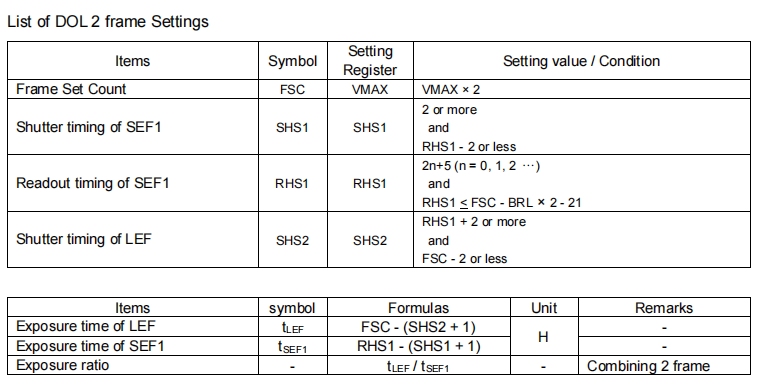
DOL 两帧设置与曝光公式 — 英文原图,PDF 第 222 页
| 项目 | 符号 | 设置寄存器 | 设置值 / 条件 |
|---|---|---|---|
| 帧设置计数 | FSC | VMAX | VMAX × 2 |
| SEF1 快门时序 | SHS1 | SHS1 | ≥ 2 且 ≤ RHS1 - 2 |
| SEF1 读出时序 | RHS1 | RHS1 | 2n+5 (n = 0, 1, 2 …) 且 RHS1 ≤ FSC - BRL × 2 - 21 |
| LEF 快门时序 | SHS2 | SHS2 | ≥ RHS1 + 2 且 ≤ FSC - 2 |
| 项目 | 符号 | 公式 | 单位 | 备注 |
|---|---|---|---|---|
| LEF 曝光时间 | t_LEF | FSC - (SHS2 + 1) | H | - |
| SEF1 曝光时间 | t_SEF1 | RHS1 - (SHS1 + 1) | H | - |
| 曝光比 | - | t_LEF / t_SEF1 | - | 两帧合成 |
CISHdrTimeRegMin:
可通过表格计算长帧最小曝光:
长帧曝光 = FSC-SHS2-1=FSC-(FSC-2)-1=1
短帧曝光 = RHS1-SHS1-1=RHS1-(SHS1-2)-1=1(原文公式保留,代入项疑点见校对记录。)
因此 HDR 下最小曝光为 1 行。
CISHdrTimeRegOdevity:从表中可见,shs1、shs2 没有 2n 或 2n+1 等限制,因此相应曝光行数可逐 1 增加。
CISHdrTimeRegSumFac:
长短帧曝光之和 =(FSC-SHS2-1)+ (RHS1-SHS1-1)
SHS2、SHS1 同时取最小值,可使长短帧曝光均最大。
长短帧曝光之和 =(FSC-(RHS1+2)-1)+ (RHS1-2-1)=FSC-6
两帧 DOL HDR 中 FSC=2vts,因此长短帧最大曝光之和为 2vts-6。
即 CISHdrTimeRegSumFac=[2 6]。但为便于计算,Sony DOL HDR 驱动将 FSC 作为 vts 上报给 AEC,即上报的 vts 实际已翻倍,因此 CISHdrTimeRegSumFac=[1 6]。
CISTimeRegUnEqualEn=1
长短帧曝光时间是否可相等。由于 imx290 短帧限制,任何情况下均不能相等。
CISHdrGainIndSetEn=1
长短帧增益是否必须相同:1 表示可不同,0 表示必须相同。详见传感器说明。有些传感器长短帧共用一组寄存器;有些虽各有增益寄存器,但设计要求两组设为同值。为保证曝光分解正确,必须准确填写。
注意:
imx290 需注意 FPGC PFGC_1 值的设置,DOL 文档有具体说明。
FullResolution=1920x1080
GainRange=1 2 20 20 1 0 20 2 4 10 0 1 20 40 4 8 5 -20 1 40 60 8 16 2.5 -40 1 60 80 16 32 1.25 -60 1 80 100 32 64 0.625 -80 1 100 120 64 128 0.3125 -100 1 120 140 128 256 0.15625 -120 1 140 160 256 512 0.078125 -140 1 160 180 512 1024 0.0390625 -160 1 180 200
IsLinear=0
RK 平台支持倍数形式增益及 Sony dB 模式增益,0 表示使用 dB。imx290 可直接用 dB 方法,也可用上述 GainRange 分解公式;非线性曲线拆成多段线性曲线会产生少量误差。
NonLinear=DB_MODE
PatternMode=RGGB
TimeFactor=0 0 1 0.5
曝光时间分解公式:建议保留;计算不符合公式时,由传感器驱动转换。
hdr_dcg_ratio=2
normal_dcg_ratio=2
DCG 比例已在上文说明。
SensorFlip=0
默认镜像翻转状态:bit0 为镜像,bit1 为翻转。
20. 附录 A:CIS 驱动 V4L2-controls 列表
| CID | 说明 |
|---|---|
| V4L2_CID_VBLANK | 垂直消隐:每帧后无图像数据的空闲期,单位为行。每行长度为图像宽度加水平消隐,以同一子设备 V4L2_CID_PIXEL_RATE 定义的像素率计时。 |
| V4L2_CID_HBLANK | 水平消隐:每行图像后无数据的空闲期,单位为像素。 |
| V4L2_CID_EXPOSURE | 决定 sensor 曝光时间,受帧间隔限制。 |
| V4L2_CID_ANALOGUE_GAIN | 模拟增益作用于像素矩阵全部颜色分量,在 A/D 转换之前于模拟域执行。 |
| V4L2_CID_PIXEL_RATE | Subdev 源 pad 的像素速率,此 control 只读,单位为像素/秒。例如 MIPI 总线:pixel_rate = link_freq * 2 * nr_of_lanes / bits_per_sample。 |
| V4L2_CID_LINK_FREQ | 数据总线频率与 media bus 像素码、总线类型(每样本时钟周期数)共同决定像素阵列的 V4L2_CID_PIXEL_RATE,非 sensor 设备也可能在其他位置定义。帧率可由像素时钟、宽高和水平/垂直消隐计算。虽然 pixel rate 可定义在不含像素阵列的 subdev,但不能据此求帧率,因为只有像素阵列上的消隐信息精确且不允许其他消隐。通过选择水平和垂直消隐来选择帧率。本 control 单位 Hz。 |
21. 附录 B:MEDIA_BUS_FMT 表
| CIS sensor 类型 | Sensor 输出格式 |
|---|---|
| Bayer RAW | MEDIA_BUS_FMT_SBGGR10_1X10 MEDIA_BUS_FMT_SRGGB10_1X10 MEDIA_BUS_FMT_SGBRG10_1X10 MEDIA_BUS_FMT_SGRBG10_1X10 MEDIA_BUS_FMT_SRGGB12_1X12 MEDIA_BUS_FMT_SBGGR12_1X12 MEDIA_BUS_FMT_SGBRG12_1X12 MEDIA_BUS_FMT_SGRBG12_1X12 MEDIA_BUS_FMT_SRGGB8_1X8 MEDIA_BUS_FMT_SBGGR8_1X8 MEDIA_BUS_FMT_SGBRG8_1X8 MEDIA_BUS_FMT_SGRBG8_1X8 |
| YUV | MEDIA_BUS_FMT_YUYV8_2X8 MEDIA_BUS_FMT_YVYU8_2X8 MEDIA_BUS_FMT_UYVY8_2X8 MEDIA_BUS_FMT_VYUY8_2X8 MEDIA_BUS_FMT_YUYV10_2X10 MEDIA_BUS_FMT_YVYU10_2X10 MEDIA_BUS_FMT_UYVY10_2X10 MEDIA_BUS_FMT_VYUY10_2X10 MEDIA_BUS_FMT_YUYV12_2X12 MEDIA_BUS_FMT_YVYU12_2X12 MEDIA_BUS_FMT_UYVY12_2X12 MEDIA_BUS_FMT_VYUY12_2X12 |
| 仅输出 Y(黑白)的 raw bw sensor | MEDIA_BUS_FMT_Y8_1X8 MEDIA_BUS_FMT_Y10_1X10 MEDIA_BUS_FMT_Y12_1X12 |
22. 附录 C:CIS 参考驱动列表
| CIS 接口 | 输出类型 | 帧 / 场 | 参考驱动 |
|---|---|---|---|
| MIPI | Bayer RAW | 帧 | 0.3M: ov7750.c, gc0403.c 0.9M jx_h62.c 1.2M ov9750.c jx-h65.c 2M ov2685.c ov2680.c ov2735.c ov02g10.c ov02b10.c gc2385.c gc2355.c gc2053.c sc2232.c sc2239.c sc223a sc210iot.c sp250a.c 4M gc4c33.c jx_k04.c os04c10.c sc401ai.c 5M ov5695.c ov5648.c ov5670.c gc5024.c gc5025.c gc5035.c hm5040.c sc5239.c hynix_hi556.c 8M ov8858.c |
| CIS 数据接口 | CIS 输出数据类型 | 帧/场 | 参考驱动 |
|---|---|---|---|
| os08a10.c os08a20.c sc8220 imx378.c imx317.c imx219.c gc8034.c hynix_hi846.c s5kgm1sp.c s5k4h7yx.c 13M ov13850.c ov13b10.c imx258.c ov12d2q.c | |||
| MIPI | Bayer raw HDR | 帧 | 2M imx307.c imx327.c imx462.c gc2093.c ov02k10 ov2718.c sc200ai.c sc2310.c jx-f37.c 4M ov4689.c os04a10.c imx347.c imx464.c sc4238.c 5M imx335.c os05a20.c sc500ai.c 8M imx334.c imx415.c |
| MIPI | YUV | 帧 | 2M gc2145.c |
| CIS 数据接口 | CIS 输出数据类型 | 帧/场 | 参考驱动 |
|---|---|---|---|
| MIPI | RAW BW | 帧 | 0.3M ov7251.c 1M ov9281.c 1.3M sc132gs.c |
| MIPI | YUV | field | tc35874x.c |
| ITU.BT601 | Bayer RAW | 2M imx323.c ar0230.c |
|
| ITU.BT601 | YUV | 0.3M gc0329.c gc0312.c gc032a.c 2M gc2145.c gc2155.c gc2035.c bf3925.c |
|
| ITU.BT601 | RAW BW | 0.3M sc031gs.c 1.3M sc032gs.c | |
| ITU.BT656 | Bayer RAW | 2M:imx323(可支持) |
23. 附录 D:VCM 驱动 IC 参考驱动列表
| 参考驱动 |
|---|
| vm149c.c |
| dw9714.c |
| dw9718.c |
| fp5510.c |
| gt9760s.c |
| fp5501.c(步进电机) |
| mp6507.c(步进电机) |
| ms41908.c(步进电机) |
24. 附录 E:闪光灯驱动 IC 参考驱动列表
| 参考驱动 |
|---|
| sgm3784.c |
| leds-rgb13h.c(GPIO 控制) |