
Based on the Chinese RK3588S Hardware Design Guide V1.2 (2023-12-14) for circuit and PCB review. CM7S carriers must follow module interface definitions; Sige7S supports software and peripheral evaluation. SoC capabilities are not a board connector list. Verify SDK/BSP, kernel, board revision, firmware and multiplexing. Values are source references, not ArmSoM hardware measurements.
RK3588S Hardware Design Guide V1.2 (2023-12-14), CN · §2.3.11–2.3.15
Do not mix mux groups
M0/M1/M2 locations for UART, SPI, CAN and I2C are mux choices, not additional independent controllers. Select a complete supported signal group and verify its supply domain. SPI2 is assigned to the PMIC by default and should not be casually repurposed. CAN requires an external transceiver; SoC TX/RX are not differential bus wires.
Validate each peripheral protocol
The I2C pull-up reference is 2.2kΩ; actual values depend on bus load and voltage. HDMI DDC is dedicated. V1.2 specifies CAN2.0B at 1Mbps, not a CAN FD claim. Check UART baud/flow control, SPI mode/chip select, I2C edges and CAN transceiver levels, then sleep and reset, retaining measurement records.
Design parameters and review table
| Item | Source reference |
|---|---|
| UART / general SPI | 10 / 5 controllers |
| CAN source scope | 3 controllers; CAN2.0B; 1Mbps |
| I2C reference | Up to 400Kbit/s; 2.2kΩ pull-up |
| PWM source count | 4 controllers ×4 channels |
Source figures
No corresponding English design guide was found for this batch. All four editions use Chinese source screenshots with localized captions. Open an image for full resolution; the article text and parameter tables remain copyable. Page references are physical PDF pages.
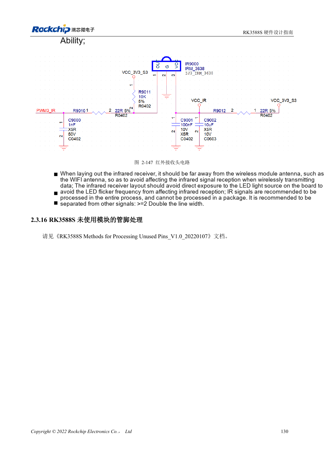
Chinese original · PDF 145 · 2-147
ArmSoM development path
CM7S supports custom carriers: first identify supplies, DDR and boot circuits already integrated in the module, then design outside its connectors. Sige7S provides a starting point for software and peripheral evaluation. For both products, verify exposed interfaces, pin assignments, levels, system images and cooling against the relevant revision. A chip reference schematic is not a product wiring diagram.