
Based on the Chinese RK3588S Hardware Design Guide V1.2 (2023-12-14) for circuit and PCB review. CM7S carriers must follow module interface definitions; Sige7S supports software and peripheral evaluation. SoC capabilities are not a board connector list. Verify SDK/BSP, kernel, board revision, firmware and multiplexing. Values are source references, not ArmSoM hardware measurements.
RK3588S Hardware Design Guide V1.2 (2023-12-14), CN · §2.2.3–2.2.5
Select the complete reference
Dual RK806-2 and single RK806-1 plus external supplies are distinct architectures, not a design with one chip removed. Migrate output allocation, defaults, sequencing, control bus, sleep and reset together. The PMIC 2.7–5.5V input is not an ArmSoM board input specification.
Synchronization and layout
EXT_EN assigns master/slave; SYNC/SYNC_CLK synchronize the dual design, with VDC/PWRON/RESET connected as shown. A single PMIC uses master mode with SYNC/SYNC_CLK open. Prioritize high-current paths and capacitor ground loops while managing heat concentration. Maximum current is not a continuous rating at every temperature.
Design parameters and review table
| Item | Source reference |
|---|---|
| RK806 input | 2.7–5.5V |
| Package | 7×7mm QFN68 |
| Dual reference | RK806-2 |
| Single reference | RK806-1 + external supplies |
Source figures
No corresponding English design guide was found for this batch. All four editions use Chinese source screenshots with localized captions. Open an image for full resolution; the article text and parameter tables remain copyable. Page references are physical PDF pages.
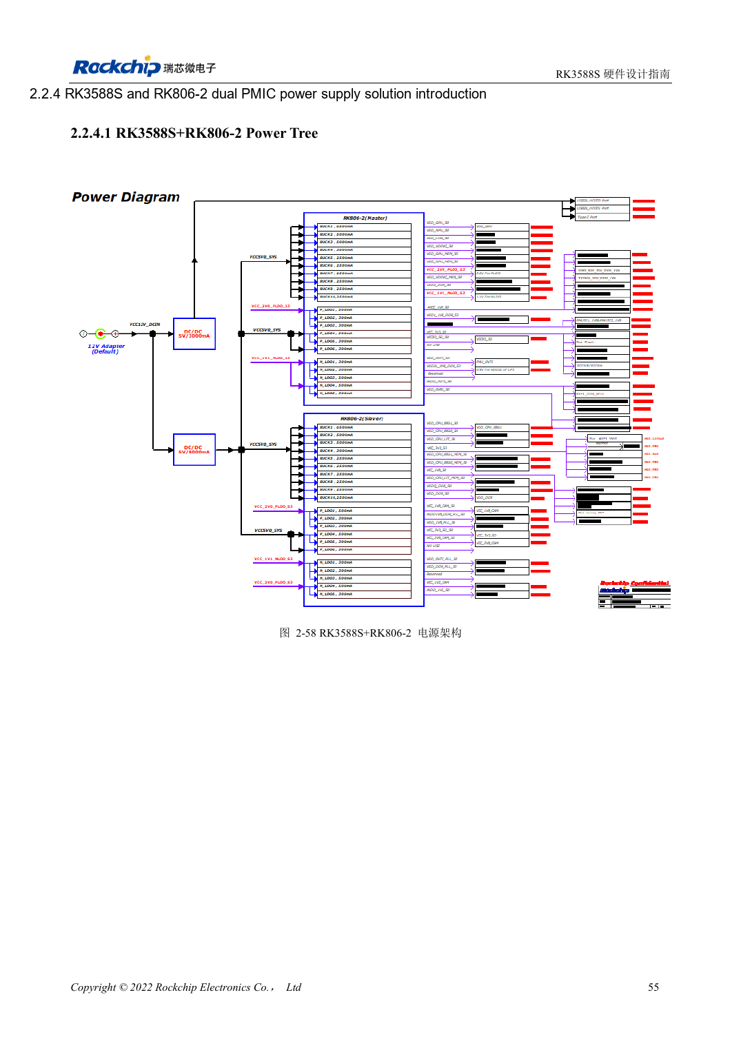
Chinese original · PDF 70 · 2-58
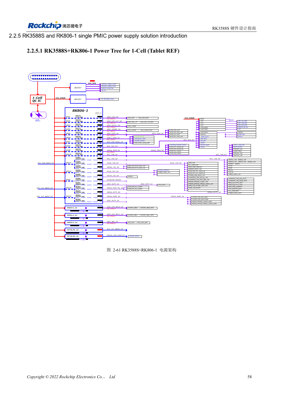
Chinese original · PDF 73 · 2-61
ArmSoM development path
CM7S supports custom carriers: first identify supplies, DDR and boot circuits already integrated in the module, then design outside its connectors. Sige7S provides a starting point for software and peripheral evaluation. For both products, verify exposed interfaces, pin assignments, levels, system images and cooling against the relevant revision. A chip reference schematic is not a product wiring diagram.