
Based on the Chinese RK3588S Hardware Design Guide V1.2 (2023-12-14) for circuit and PCB review. CM7S carriers must follow module interface definitions; Sige7S supports software and peripheral evaluation. SoC capabilities are not a board connector list. Verify SDK/BSP, kernel, board revision, firmware and multiplexing. Values are source references, not ArmSoM hardware measurements.
RK3588S Hardware Design Guide V1.2 (2023-12-14), CN · §5; §3.3.4
Place protection where current enters
TVS belongs near connectors or discharge entry points with short low-impedance ground return. Keep reset, clock and interrupt nets away from edges; the guide suggests at least 5mm. Include ESD capacitance and pads in signal-integrity analysis rather than assuming higher ratings or more capacitance always help.
Start EMI diagnosis at source and coupling path
Check broken returns, long stubs, common-mode conversion and switching supplies before choosing filters or shields. Heatsinks can radiate coupled energy; provide grounding options and test. General series-resistor advice does not override USB/HDMI/PCIe rules. Test real enclosure, cables, grounding and certification conditions; design guidance is not certification.
Design parameters and review table
| Item | Source reference |
|---|---|
| Sensitive-net edge distance | ≥5mm |
| Clock source-to-series resistor | ≤400mil |
| Power-plane edge reference | 20H; H=power/ground dielectric spacing |
| High-speed ESD | Use interface-specific capacitance limits |
Source figures
No corresponding English design guide was found for this batch. All four editions use Chinese source screenshots with localized captions. Open an image for full resolution; the article text and parameter tables remain copyable. Page references are physical PDF pages.
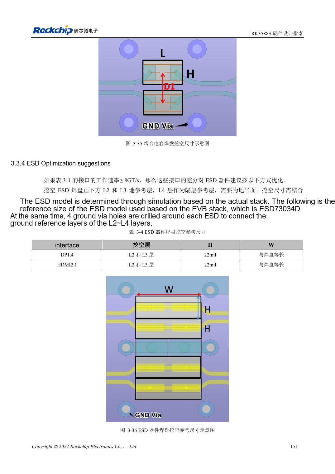
Chinese original · PDF 166 · 3-36
ArmSoM development path
CM7S supports custom carriers: first identify supplies, DDR and boot circuits already integrated in the module, then design outside its connectors. Sige7S provides a starting point for software and peripheral evaluation. For both products, verify exposed interfaces, pin assignments, levels, system images and cooling against the relevant revision. A chip reference schematic is not a product wiring diagram.