
Based on the Chinese and English RK3576 Hardware Design Guide V1.1 (2024-05-28), for SoC-board design. CM5 carriers must follow the module interface; Sige5 can establish a software/peripheral baseline. This guide does not prescribe one SDK/BSP or kernel for every product; verify each board. Values are source references, not ArmSoM measurements.
RK3576_Hardware_Design_Guide_V1.1_20240528_EN.pdf · §2.1.10; FSPI PCB
Choose a controller and a complete mux group
Two FSPI controllers support NOR/NAND with SDR 1/2/4-wire operation. FSPI0 shares pins with eMMC and VCCIO0 is 1.8V only. FSPI1_M0 uses VCCIO1 and M1 uses VCCIO3, with 1.8V or 3.3V selected for the entire IO domain. Do not assemble CLK, CS and data from different mux groups.
Make chip select reliable during power-up
D2/D3 require external 10kΩ pull-ups in single-wire operation. FSPI1_M0 CSN defaults low and needs an external pull-up: the table specifies 2.2kΩ, while prose lists 2.2kΩ/4.7kΩ. Confirm the current reference BOM and timing. Match flash supply to its IO domain and pull CS high with the supply. Boot probing changes pulls on GPIO1_B0 and GPIO1_C2; avoid using these for sensitive enables.
Validate routing and recoverability together
Reserve 0Ω on CLK at the SoC. Check 50Ω single-ended routing, clock/data mismatch below 200mil and length below 4inch. Keep independent USB recovery access. Test blank flash, a damaged image, power interruption around programming and normal cold boot; one successful download is insufficient.
Design parameters and review table
| Item | Source reference |
|---|---|
| FSPI0 | VCCIO0 = 1.8V |
| FSPI1_M0 / M1 | VCCIO1 / VCCIO3 |
| Z | 50Ω ±10% |
| CLK ↔ DATA | <200mil |
| Trace length | <4inch |
Source figures
The reference pages below contain the relevant circuit or timing figures; click for full resolution. Designators and component values belong to the reference design, not an ArmSoM product schematic.
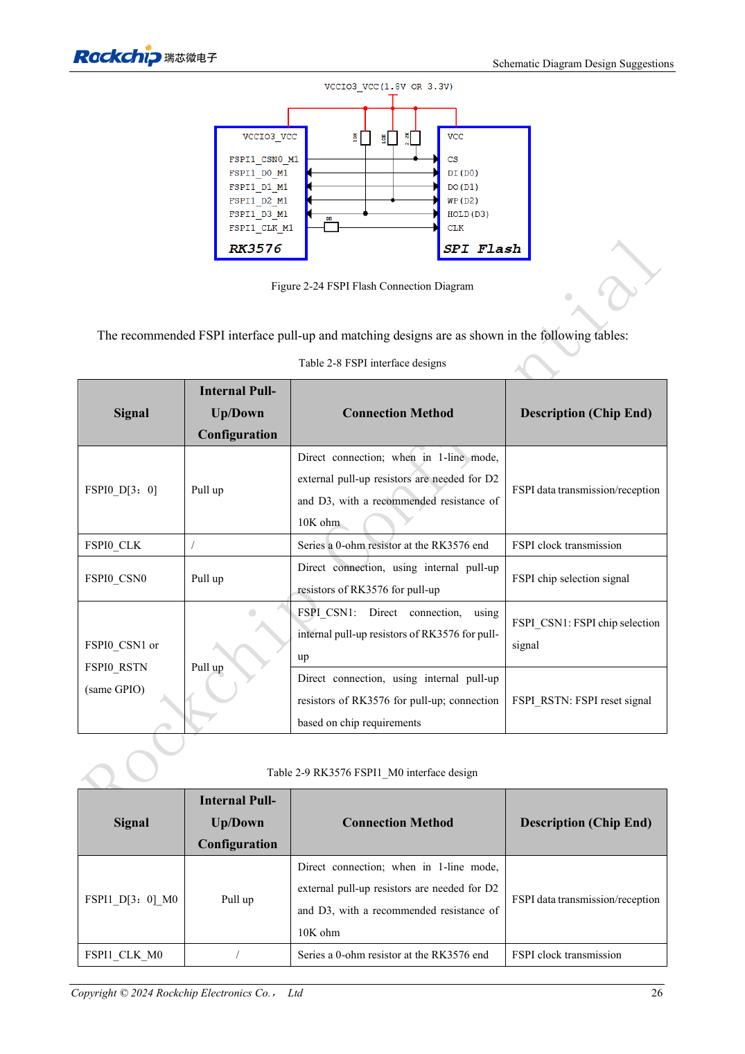
English original · PDF 45 · 2-24
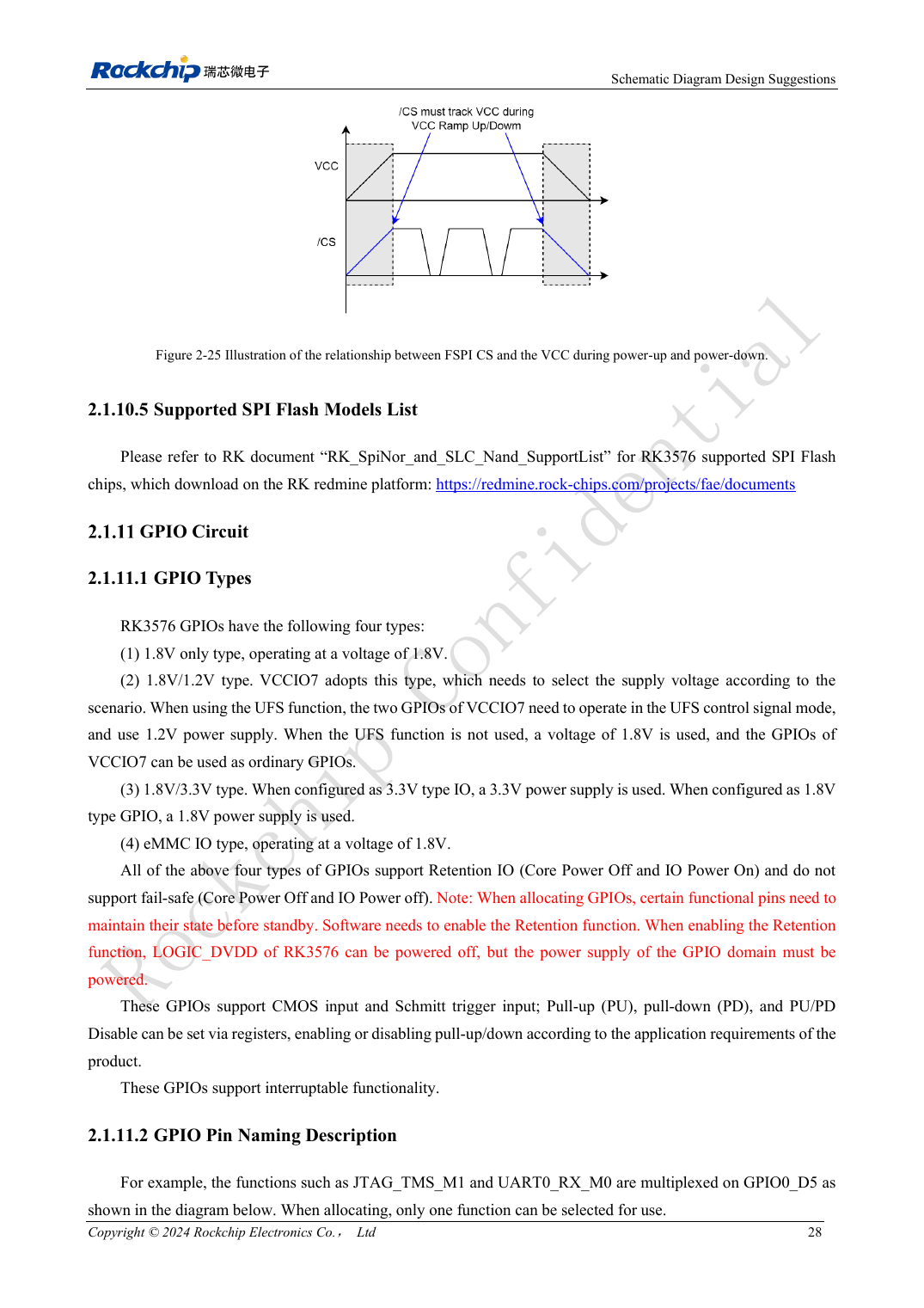
English original · PDF 47 · 2-25
ArmSoM development path
CM5 reduces repeated compute-core design on custom carriers; Sige5 provides a starting point for software and peripheral evaluation. Verify exposed interfaces, connector pins, voltages and image support in board documentation rather than inferring them from SoC features.