
Based on the Chinese and English RK3576 Hardware Design Guide V1.1 (2024-05-28), for SoC-board design. CM5 carriers must follow the module interface; Sige5 can establish a software/peripheral baseline. This guide does not prescribe one SDK/BSP or kernel for every product; verify each board. Values are source references, not ArmSoM measurements.
RK3576_Hardware_Design_Guide_V1.1_20240528_EN.pdf · §2.3.1; SDMMC/SDIO PCB; §3.5.25
Separate boot-capable SDMMC0 from SDMMC1
Both controllers support four-bit SDIO 3.0/MMC 4.51 and SDR104 clocks up to 200MHz. SDMMC0 uses VCCIO1 and can boot; SDMMC1 uses VCCIO3 or VCCIO4 and is not an equivalent boot port. Card supply stays at 3.3V. Negotiated SD 3.0 switching changes IO voltage, not the card supply to 1.8V.
Power switching and insertion
The reference uses 22Ω on D/CMD/CLK and 100Ω on DETN; SD 3.0 protection capacitance must be below 1pF. Boot probing raises GPIO0_B6/PWREN, so use non-inverting load-switch control and provide discharge for reinsertion. DETN can become high impedance in low power; determine whether its external pull-up requires an always-on supply for the intended wake scheme.
Wi-Fi also needs RF and peak-current validation
Match module VDDIO, 32.768kHz clock voltage and UART/PCM direction. Keep the module away from DDR, HDMI and power inductors. Route RF at 50Ω without branches and reserve matching components; antenna clearance follows its supplier. Size supplies for the actual module peak current, not average current. Exercise Wi-Fi alongside nearby fast peripherals and record throughput, losses, disconnections and supply droop.
Design parameters and review table
| Item | Source reference |
|---|---|
| SD Z | 50Ω ±10% |
| CLK ↔ DATA | <120mil |
| Trace length | <4inch |
| RF Z | 50Ω ±10% |
| SD3 ESD | <1pF |
Source figures
The reference pages below contain the relevant circuit or timing figures; click for full resolution. Designators and component values belong to the reference design, not an ArmSoM product schematic.
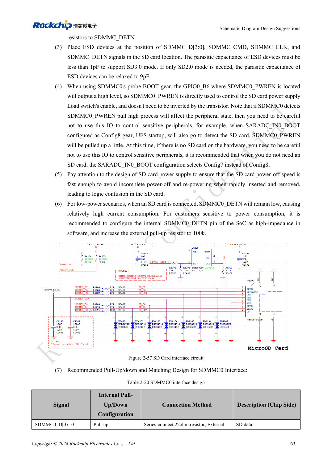
English original · PDF 82 · 2-57
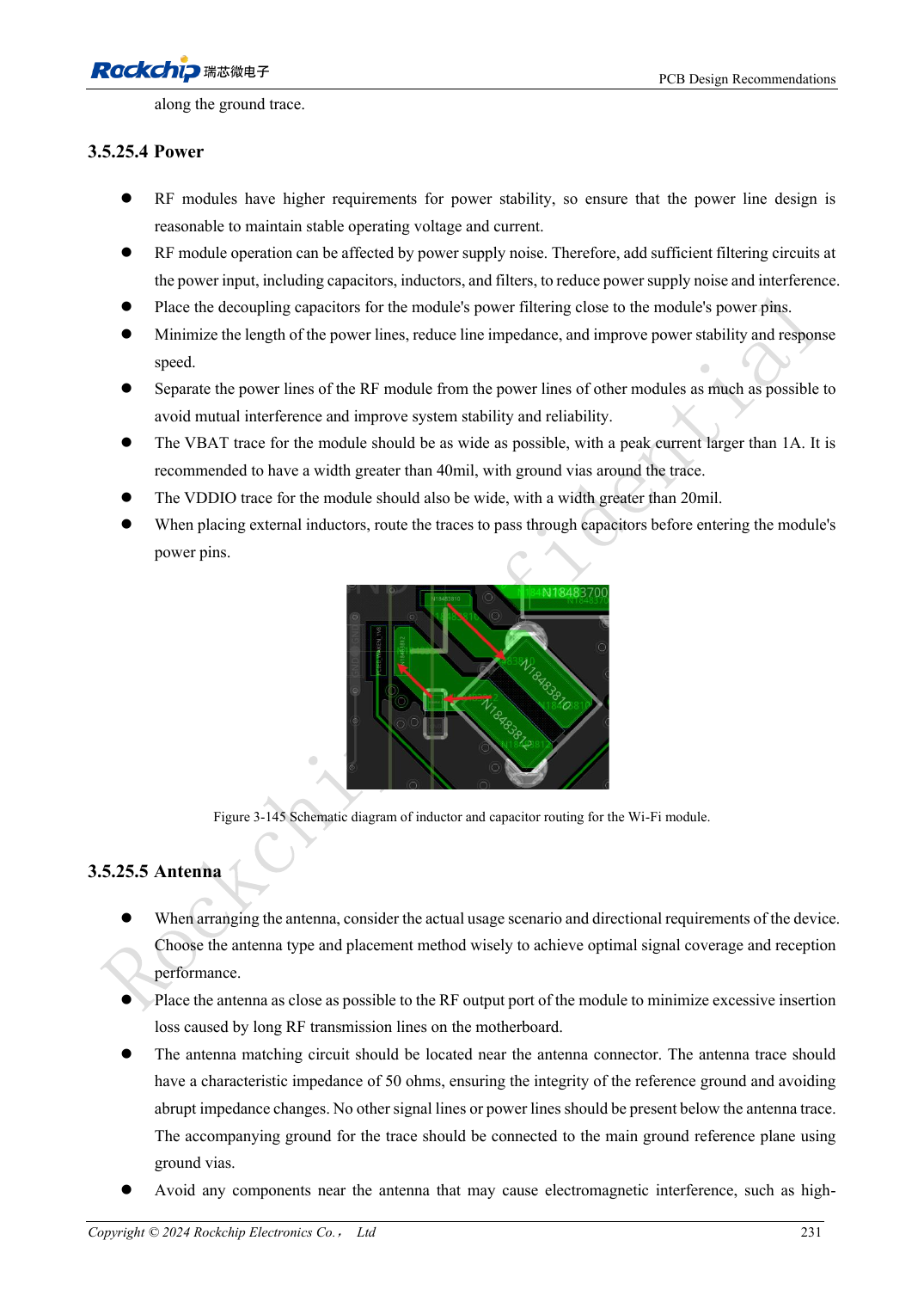
English original · PDF 250 · 3-145
ArmSoM development path
CM5 reduces repeated compute-core design on custom carriers; Sige5 provides a starting point for software and peripheral evaluation. Verify exposed interfaces, connector pins, voltages and image support in board documentation rather than inferring them from SoC features.