
This task-focused guide explains the source with key specifications, limitations and original figures. It is not a page-by-page translation or a complete pin/register manual. Vendor examples are not ArmSoM measurements. Check the actual board revision, schematic, SDK/BSP, kernel and drivers before applying them; no new hardware validation was performed for this article.
Primary source: Rockchip_RK3576_EVB1_User_Guide_V1.0_CN.pdf · PDF 53 pages.
Identify the reference revision
The manual targets RK_EVB1_RK3576_LP4XD200P132SD6_V10_20231211YWQ_final. Its table lists 8GB LPDDR4x, 128GB UFS and eMMC N/A, with a 12V/3A kit supply. This is EVB1 configuration, not CM5 or Sige5 configuration. Both ArmSoM products use RK3576, but migration requires their own schematics and BSP.
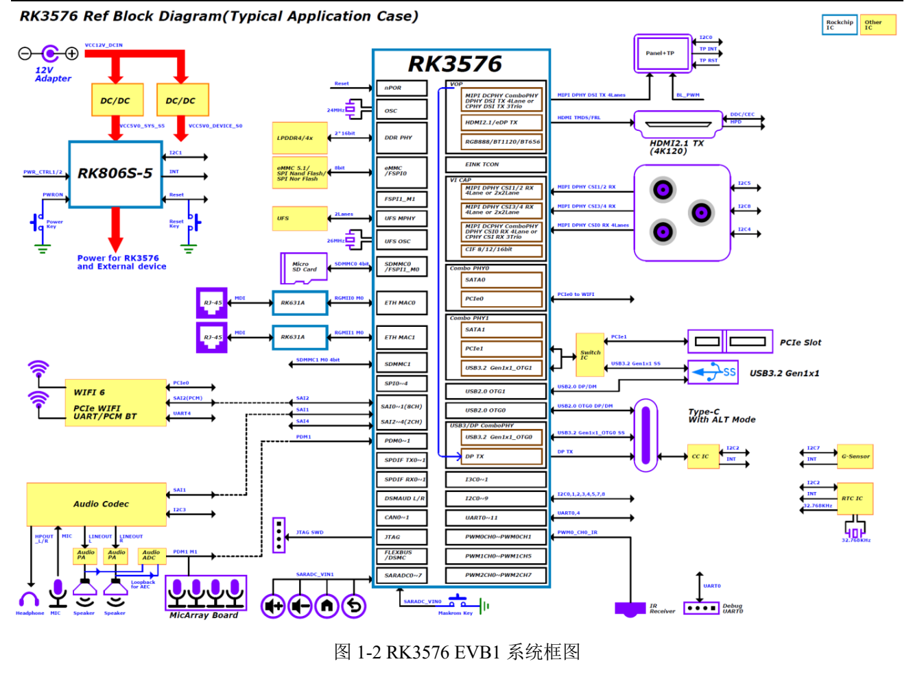
RK3576 EVB1 system diagram — Original Chinese figure; no corresponding English figure was found in this batch. Rockchip_RK3576_EVB1_User_Guide_V1.0_CN.pdf, PDF p. 12.
Identify ports before applying power
The main Type-C handles downloading and DP Alt Mode; another Type-C is USB-UART Debug. Connect debug to the PC, identify its COM port and use the source’s 1500000 (1.5M) baud rate. Ensure the serial path supports it and capture logs from reset onward.
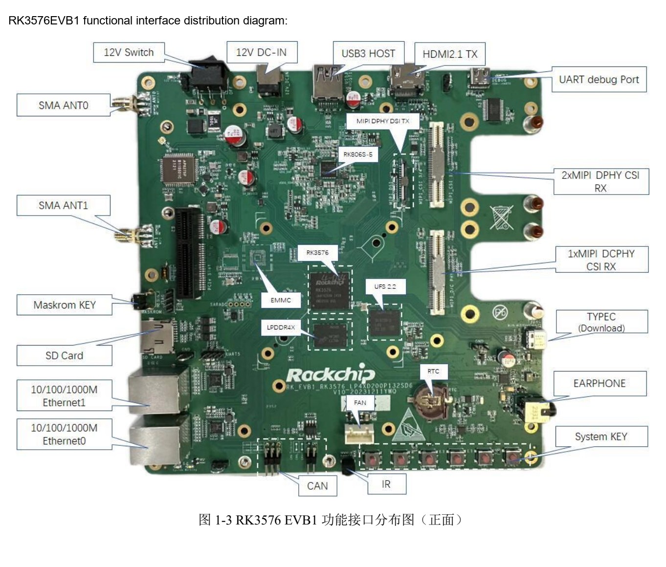
RK3576 EVB1 interface layout — Original Chinese figure; no corresponding English figure was found in this batch. Rockchip_RK3576_EVB1_User_Guide_V1.0_CN.pdf, PDF p. 14.
Loader, MASKROM and USB3 download
- Match image, Loader, Parameter and Uboot to storage and board revision; back up data.
- For reference-board MASKROM, connect download Type-C, hold MASKROM, apply power and enable the switch; release after detection.
- For Loader, hold Volume+(RECOVERY) during power-on/reset and release after detection. The source associates this with low
SARADC_IN1. - The source requires tool v3.28 or later. Its USB3 configuration in
config.iniis below; device support still determines whether USB3 is selected.
USB3_TRANSFER=TRUE
This is a source example, not a setting for every software release. Consult CM5/Sige5 documentation for buttons, supplies and download ports rather than copying the EVB’s 12V procedure.
Three common interface mistakes
Slot shape is not link width. The source describes a PCIex4 connector but lists 1 active lane and an alternative relationship with USB3.0 Host. Check supply, lanes, PHY and BSP before choosing an expansion card; do not infer x4 throughput from the connector.
A camera connector is not universal plug-and-play. The guide provides DCPHY/DPHY paths, an 80pin connector and an IMX415 example. The overview gives DCPHY as 1×3 trios CPHY, with differing wording later. Confirm mode using the actual schematic and formal chip information rather than adding interface counts. Power, reset, clock, I2C and driver must agree.
USB wake depends on hardware power. Page 30 lists resistor changes keeping Host 5V, USB PHY and oscillator supplied. A software property alone does not guarantee wake. Every resistor reference belongs only to the named EVB revision.
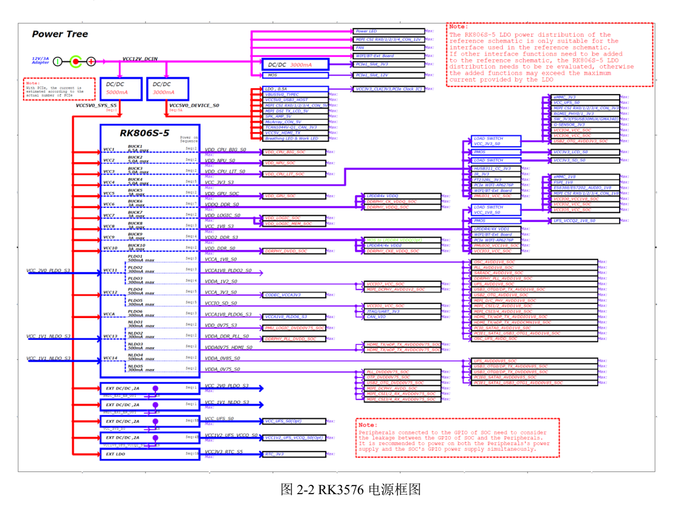
RK3576 EVB1 power tree — Original Chinese figure; no corresponding English figure was found in this batch. Rockchip_RK3576_EVB1_User_Guide_V1.0_CN.pdf, PDF p. 23.
Selected I2C addresses and voltages
| EVB bus | Device | Source address | Voltage |
|---|---|---|---|
| I2C1_M0 | RK806S-5 | 0x23 |
1.8V |
| I2C2_M0 | HYM8563TS / HUSB311 | 0x51 / 0x4E |
3.3V |
| I2C3_M0 | ES8388 / ES7202 | 0x11 / 0x30 |
1.8V |
| I2C4_M3 | CAM0 | 0x1A |
1.8V |
These are selected known entries from p. 23. Other camera, touch and MicArray entries include TBD; do not invent addresses. Check conflicts, pull-up supplies and reverse powering during sleep before adding devices.
Debugging and migration checklist
The manual disables JTAG use with an inserted SD card, and also marks CAN as sharing with SD Card. The fan section lists 12V/5V support, default 12V, but says EVB1 does not yet support Sensor speed control. A connector does not prove closed-loop fan control.
For an image that enables ADB, the source’s connection checks are:
adb devices
adb shell
Validate supply, downloading, serial output, storage, display, networking and camera in sequence, then concurrency and suspend/resume. CM5 carriers and Sige5 use their own pins, storage, firmware and power requirements. The EVB provides a troubleshooting method.
Products and development resources
- CM5 — Product · Documentation
- Sige5 — Product · Documentation