
Source RK-KF-YF-127 V1.1.1, RK805, Linux 3.10 / 4.4 / 4.19. Covers PMIC submodules, concepts, functions, DTS and issue diagnosis. Platform reference only: verify the ArmSoM board PMIC, SoC, SDK/BSP, kernel, supplies and wiring. No ArmSoM hardware validation. Only a Chinese source is available; all four languages use its original figures, including any embedded English labels. No corresponding English PDF exists in this batch. Hardware commands are documented, not executed.
1. Basics
1.1 Overview
RK805 is a high-performance PMIC integrating 4 high-current DCDCs, 3 LDOs, 1 RTC and adjustable power-on sequencing. System supplies are generally DCDC or LDO; their characteristics follow (consult detailed references separately).
- DCDC: high efficiency at large input/output voltage differences, but high ripple and cost; suitable for large voltage differences and high-current loads. PWM has good ripple transient response but lower efficiency; PFM is efficient but has limited load capability.
- LDO: low efficiency at large voltage differences and low cost. For example, a 1.1V LDO output can be supplied from the VCCIO_3.3V DCDC to improve efficiency. Where the circuit permits, feed the LDO from a DCDC output, taking power-on sequencing into account.
1.2 Functions
RK805 functions can be grouped into four parts:
- Regulator: control each DCDC/LDO power state.
- RTC: clock timekeeping and timers.
- GPIO: out1 and out2 are push-pull output pins, usable as ordinary GPIOs but output-only.
- Pwrkey: detect power-button press/release, saving an AP GPIO.
1.3 Chip pin functions
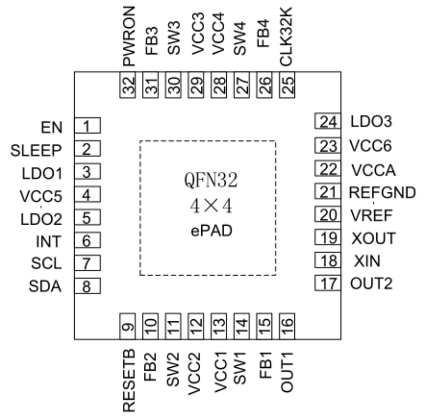
Original figure from Chinese PDF — p.5
Pay particular attention to SLEEP and INT in the following description.
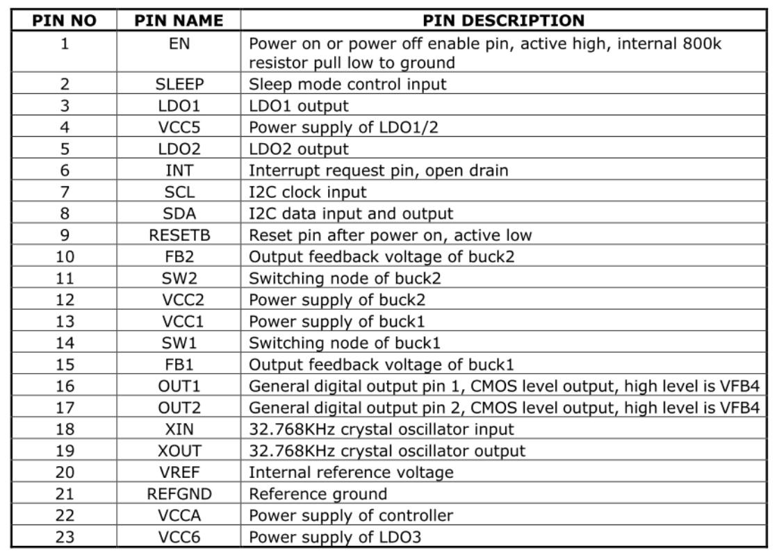
Original figure from Chinese PDF — p.5
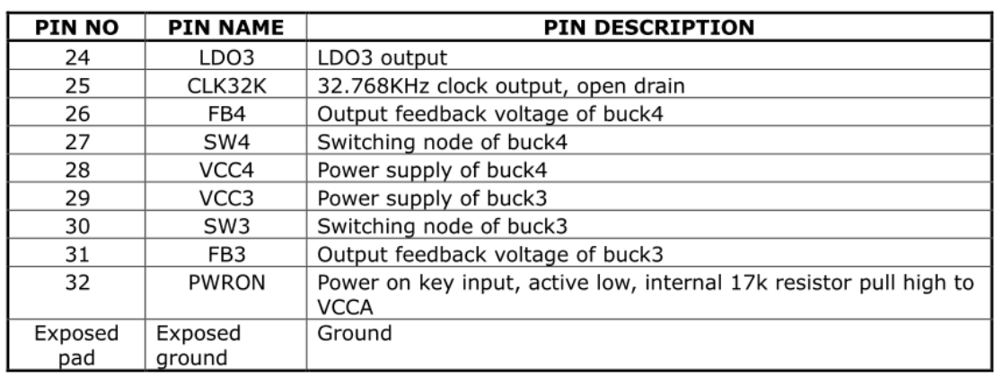
Original figure from Chinese PDF — p.6
Pin definitions (transcribed row by row from the figures above; source names and I/O markers retained)
| Pin No. | Pin name | Description |
|---|---|---|
| 1 | EN | Power on/off enable, active high, internal 800k pull-down to ground |
| 2 | SLEEP | Sleep mode control input |
| 3 | LDO1 | LDO1 output |
| 4 | VCC5 | Power supply of LDO1/2 |
| 5 | LDO2 | LDO2 output |
| 6 | INT | Interrupt request pin, open drain |
| 7 | SCL | I2C clock input |
| 8 | SDA | I2C data input and output |
| 9 | RESETB | Reset pin after power on, active low |
| 10 | FB2 | Output feedback voltage of buck2 |
| 11 | SW2 | Switching node of buck2 |
| 12 | VCC2 | Power supply of buck2 |
| 13 | VCC1 | Power supply of buck1 |
| 14 | SW1 | Switching node of buck1 |
| 15 | FB1 | Output feedback voltage of buck1 |
| 16 | OUT1 | General digital output pin1, CMOS output, high level is VFB4 |
| 17 | OUT2 | General digital output pin2, CMOS output, high level is VFB4 |
| 18 | XIN | 32.768KHz crystal oscillator input |
| 19 | XOUT | 32.768KHz crystal oscillator output |
| 20 | VREF | Internal reference voltage |
| 21 | REFGND | Reference ground |
| 22 | VCCA | Power supply of controller |
| 23 | VCC6 | Power supply of LDO3 |
| 24 | LDO3 | LDO3 output |
| 25 | CLK32K | 32.768KHz clock output, open drain |
| 26 | FB4 | Output feedback voltage of buck4 |
| 27 | SW4 | Switching node of buck4 |
| 28 | VCC4 | Power supply of buck4 |
| 29 | VCC3 | Power supply of buck3 |
| 30 | SW3 | Switching node of buck3 |
| 31 | FB3 | Output feedback voltage of buck3 |
| 32 | PWRON | Power on key input, active low, internal 17k pull-up to VCCA |
| Exposed pad | Exposed ground | Ground |
1.4 Important concepts
I2C 7-bit slave address: 0x18. PMIC has three operating modes.
- Normal mode: during normal system operation PMIC is in normal mode and pmic_sleep is low.
- Sleep mode: to minimize standby power, PMIC reduces its own consumption, lowers selected output voltages or turns outputs off according to product needs. AP configures pmic_sleep for sleep via I2C, then raises it to enter sleep. On SoC wake-up it returns low and PMIC exits sleep.
- Shutdown mode: AP configures pmic_sleep for shutdown via I2C and raises it to power down the entire system.
- pmic_sleep: low means normal operation; high selects sleep or shutdown.
- pmic_int: normally high, low on interrupt and remains low until handled.
- out1/out2: push-pull general GPIO outputs only.
- pmic_pwron: connect the power button; the driver detects press/release.
- DCDC supports PWM (force PWM), PFM, and AUTO switching between them. AUTO is efficient but has poorer ripple transient response. For stability, runtime uses PWM and sleep uses AUTO PWM/PFM.
- DCDC3 voltage adjustment:
DCDC3 voltage cannot be changed through registers, only through external divider resistors. Change the peripheral hardware if necessary; Rockchip typically uses it for VCC_DDR. Runtime DCDC/LDO adjustment ranges follow.
- DCDC voltage range is discontinuous:
| Voltage range(V) | Step(mV) | Values(V) |
|---|---|---|
| 0.7125 ~ 1.45 | 12.5 | 0.7125、0.725、0.737.5、 ……、1.45 |
| 1.8 ~ 2.2 | 200 | 1.8、 2.0、2.2 |
| 2.3 | None | 2.3 |
- LDO voltage range is continuous:
| Voltage range(V) | Step(mV) | Values(V) |
|---|---|---|
| 0.8 ~ 3.4 | 100 | 0.8、 0.9、1.0、1.1、 1.2、 …… 3.4 |
1.5 Power-on conditions and sequence
- Power-on: any condition suffices: EN changes from low to high; EN stays high and RTC alarm interrupt occurs; EN stays high and PWRON is pressed.
- Different SoC platforms may require different supply sequences. See the latest datasheet for the following available sequences.
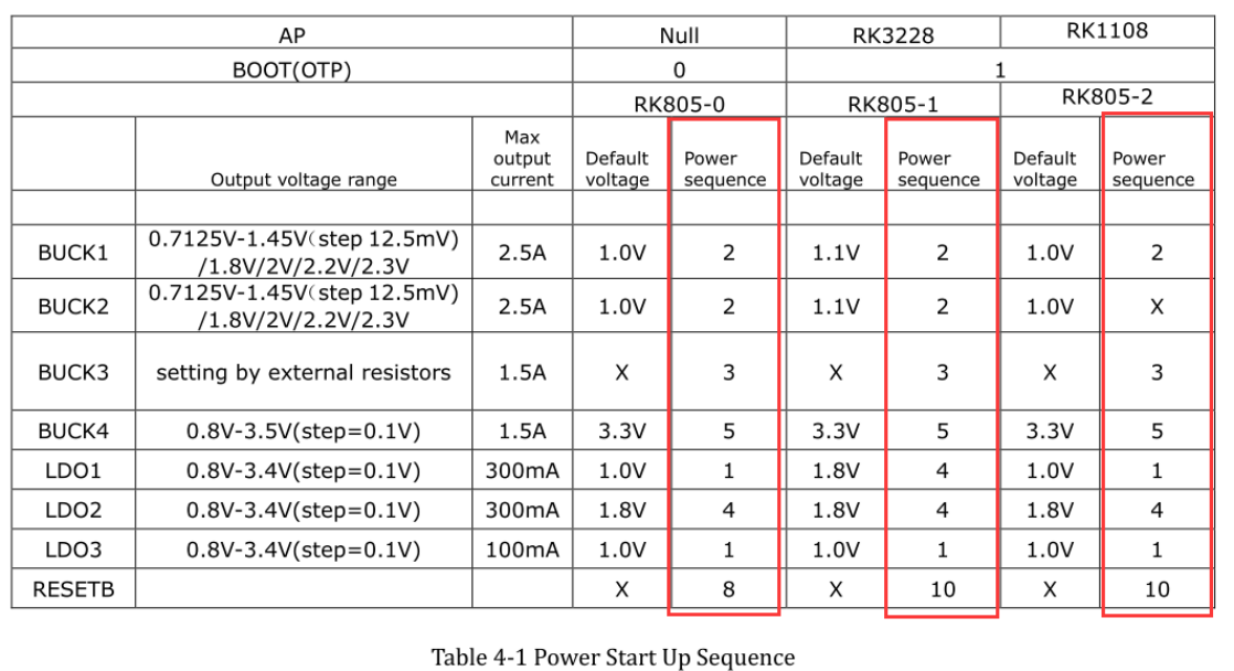
Original figure from Chinese PDF — p.7
Editable transcription of source Table 4-1: RK805-0 AP=Null, BOOT(OTP)=0; RK805-1 AP=RK3228, BOOT(OTP)=1; RK805-2 AP=RK1108, BOOT(OTP)=1.
| Output | Voltage range (step) | Max current | RK805-0 voltage / sequence | RK805-1 voltage / sequence | RK805-2 voltage / sequence |
|---|---|---|---|---|---|
| BUCK1 | 0.7125V–1.45V (12.5mV) / 1.8V / 2V / 2.2V / 2.3V | 2.5A | 1.0V / 2 | 1.1V / 2 | 1.0V / 2 |
| BUCK2 | 0.7125V–1.45V (12.5mV) / 1.8V / 2V / 2.2V / 2.3V | 2.5A | 1.0V / 2 | 1.1V / 2 | 1.0V / X |
| BUCK3 | Set by external resistors | 1.5A | X / 3 | X / 3 | X / 3 |
| BUCK4 | 0.8V–3.5V (0.1V) | 1.5A | 3.3V / 5 | 3.3V / 5 | 3.3V / 5 |
| LDO1 | 0.8V–3.4V (0.1V) | 300mA | 1.0V / 1 | 1.8V / 4 | 1.0V / 1 |
| LDO2 | 0.8V–3.4V (0.1V) | 300mA | 1.8V / 4 | 1.8V / 4 | 1.8V / 4 |
| LDO3 | 0.8V–3.4V (0.1V) | 100mA | 1.0V / 1 | 1.0V / 1 | 1.0V / 1 |
| RESETB | X / 8 | X / 10 | X / 10 |
2. Configuration
2.1 Driver and menuconfig
Kernel 3.10 configuration. RK805 reuses the RK816 driver:
drivers/mfd/rk816.c
drivers/input/misc/rk816-pwrkey.c
drivers/rtc/rtc-rk816.c
drivers/gpio/gpio-rk816.c
drivers/regulator/rk816-regulator.c
Corresponding menuconfig options:
CONFIG_MFD_RK816
CONFIG_GPIO_RK816
CONFIG_RTC_RK816
CONFIG_REGULATOR_RK816
CONFIG_INPUT_RK816_PWRKEY
Kernel 4.4 configuration. RK805 driver files:
drivers/mfd/rk808.c
drivers/input/misc/rk8xx-pwrkey.c
drivers/rtc/rtc-rk808.c
drivers/gpio/gpio-rk8xx.c
drivers/regulator/rk818-regulator.c
drivers/clk/clk-rk808.c
Corresponding menuconfig options:
CONFIG_MFD_RK808
CONFIG_RTC_RK808
CONFIG_GPIO_RK8XX
CONFIG_REGULATOR_RK818
CONFIG_INPUT_RK8XX_PWRKEY
CONFIG_COMMON_CLK_RK808
Kernel 4.19 configuration. RK805 driver files:
drivers/mfd/rk808.c
drivers/input/misc/rk805-pwrkey.c       // 跟4.4内核不同
drivers/rtc/rtc-rk808.c
drivers/pinctrl/pinctrl-rk805.c         // 跟4.4内核不同
drivers/regulator/rk808-regulator.c     // 跟4.4内核不同
drivers/clk/clk-rk808.c
Corresponding menuconfig options:
CONFIG_MFD_RK808
CONFIG_RTC_RK808
CONFIG_PINCTRL_RK805
CONFIG_REGULATOR_RK808
CONFIG_INPUT_RK805_PWRKEY
CONFIG_COMMON_CLK_RK808
2.2 DTS configuration
Kernel 3.10 DTS includes I2C attachment, main node, regulator, rtc and poweroff.
&i2c1 {
    rk805: rk805@18 {
        reg = <0x18>;
        status = "okay";
    };
};

#include "../../../arm/boot/dts/rk805.dtsi"
&rk805 {
    gpios = <&gpio2 GPIO_A6 GPIO_ACTIVE_HIGH>, <&gpio2 GPIO_D2 GPIO_ACTIVE_LOW>;
    rk805,system-power-controller;
    gpio-controller;
    #gpio-cells = <2>;

    rtc {
        status = "disabled";
    };

    regulators {
        rk805_dcdc1_reg: regulator@0 {
            regulator-name = "vdd_logic";
            regulator-min-microvolt = <700000>;
            regulator-max-microvolt = <1500000>;
            regulator-initial-mode = <0x1>;
            regulator-initial-state = <3>;
            regulator-boot-on;
            regulator-always-on;
            regulator-state-mem {
                regulator-state-mode = <0x2>;
                regulator-state-enabled;
                regulator-state-uv = <1000000>;
            };
        };
        rk805_dcdc2_reg: regulator@1 {
                    .............
        };
        rk805_dcdc3_reg: regulator@2 {
                    .............
        };
        .................................
    };
};
- Attach the complete rk805 node below its I2C node and set status = “okay”.
- Main node: the following must not be modified.
rk805,system-power-controller:声明RK805具备管理系统下电的功能;
gpio-controller:声明RK805具有GPIO的功能;
#gpio-cells:使⽤者引⽤RK805的GPIO时需要指定的参数个数;
To reference an RK805 GPIO use gpios = <&rk805 0 GPIO_ACTIVE_LOW>;. Parameter 1 is fixed &rk805; parameter 2 is 0 (out1) or 1 (out2); parameter 3 is polarity. Editable gpios in the main node specifies pmic_int first and pmic_sleep second.
- Regulator properties:
- regulator-name: supply name, preferably matching the schematic; matched by regulator_get.
- regulator-min-microvolt / regulator-max-microvolt: minimum/maximum runtime voltage.
- regulator-initial-mode: runtime DCDC mode, usually 1; 1 force pwm, 2 auto pwm/pfm.
- regulator-state-mode: sleep DCDC mode, usually 2; same values.
- regulator-initial-state: suspend mode, must be 3.
- regulator-boot-on: enable at registration.
- regulator-always-on: forbid runtime shutdown and enable at registration.
- regulator-state-enabled: keep powered in sleep; replace with regulator-state-disabled to turn off.
- regulator-state-uv: standby voltage when sleep does not cut power.
When regulator-min-microvolt and regulator-max-microvolt are equal, registration automatically sets that voltage and enables the supply. regulator-boot-on or regulator-always-on also causes automatic enabling: equal limits set the specified voltage; unequal limits retain the PMIC hardware default power-on voltage.
- RTC: to disable RTC, for example in a box product, add its node and explicitly set status = “disabled”. To enable it, remove the entire RTC node or set status = “okay”.
- Poweroff
gpio_poweroff {
    compatible = "gpio-poweroff";
    gpios = <&gpio2 GPIO_D2 GPIO_ACTIVE_HIGH>;
    status = "okay";
};
RK805 powers down the entire PMIC by raising pmic_sleep. Add this node under the root; gpios is editable and identifies pmic_sleep.
Kernel 4.4 DTS includes I2C attachment, main node, rtc, pwrkey, gpio and regulator.
&pinctrl {
    pmic {
        pmic_int_l: pmic-int-l {
        rockchip,pins =
            <2 6 RK_FUNC_GPIO &pcfg_pull_up>;   /* gpio2_a6 */
        };
    };
};

&i2c1 {
    status = "okay";
    rk805: rk805@18 {
        compatible = "rockchip,rk805";
        status = "okay";
        reg = <0x18>;
        interrupt-parent = <&gpio2>;
        interrupts = <6 IRQ_TYPE_LEVEL_LOW>;
        pinctrl-names = "default";
        pinctrl-0 = <&pmic_int_l>;
        rockchip,system-power-controller;
        wakeup-source;
        gpio-controller;
        #gpio-cells = <2>;
        rtc {
            status = "disabled";
        };
        pwrkey {
            status = "disabled";
        };
        gpio {
            status = "okay";
        };
        regulators {
            compatible = "rk805-regulator";
            status = "okay";
            #address-cells = <1>;
            #size-cells = <0>;
            vdd_logic: RK805_DCDC1@0 {
                regulator-compatible = "RK805_DCDC1";
                regulator-name = "vdd_logic";
                regulator-init-microvolt = <1100000>;
                regulator-min-microvolt = <712500>;
                regulator-max-microvolt = <1450000>;
                regulator-initial-mode = <0x1>;
                regulator-ramp-delay = <12500>;
                regulator-boot-on;
                regulator-always-on;
                regulator-state-mem {
                    regulator-mode = <0x2>;
                    regulator-on-in-suspend;
                    regulator-suspend-microvolt = <1000000>;
                };
            };

            vdd_arm: RK805_DCDC2@1 {
                .................
            };
            vcc_ddr: RK805_DCDC3@2 {
                .................
            };
            .............................
        };
    };
};
- Attach the complete rk805 node below its I2C node and set status = “okay”.
- Main node: the following must not be modified.
compatible = "rockchip,rk805";
reg = <0x18>;
rockchip,system-power-controller;
wakeup-source;
gpio-controller;
#gpio-cells = <2>;
Editable fields follow the pinctrl rules:
interrupt-parent: GPIO controller owning pmic_int; interrupts: pin index and polarity within that controller; pinctrl-names: fixed “default”; pinctrl-0: reference to pmic_int defined in pinctrl.
- rtc, pwrkey, gpio: if selected in menuconfig but not needed, add the corresponding DTS nodes with status = “disabled”. Drivers remain disabled; boot error logs may appear and can be ignored. To enable, remove the corresponding node or use status = “okay”.
- Regulator:
- regulator-compatible: registration match name; cannot change, or loading fails.
- regulator-name: supply name, preferably matching hardware; regulator_get uses it.
- regulator-init-microvolt: u-boot initial voltage, ineffective in kernel.
- regulator-min-microvolt / regulator-max-microvolt: runtime minimum/maximum.
- regulator-initial-mode: runtime DCDC mode, usually 1; 1 force pwm, 2 auto pwm/pfm.
- regulator-mode: sleep DCDC mode, usually 2; same values.
- regulator-initial-state: suspend mode, must be 3.
- regulator-boot-on: enable at registration.
- regulator-always-on: forbid runtime shutdown and enable at registration.
- regulator-ramp-delay: DCDC voltage rise time, fixed 12500.
- regulator-on-in-suspend: keep power during sleep; replace with regulator-off-in-suspend to turn off.
- regulator-suspend-microvolt: standby voltage if power stays on.
Kernel 4.19: follow the 4.4 DTS. Difference: the gpio child node is no longer required, but other modules still reference RK805 pins with gpios = <&rk805 0 GPIO_ACTIVE_LOW>;.
2.3 Function interfaces
The following interfaces cover ordinary regulator on/off, voltage setting and reading.
- Get regulator: struct regulator *regulator_get(struct device *dev, const char *id). dev may be NULL; id matches regulator-name in DTS.
- Release: void regulator_put(struct regulator *regulator)
- Enable: int regulator_enable(struct regulator *regulator)
- Disable: int regulator_disable(struct regulator *regulator)
- Read voltage: int regulator_get_voltage(struct regulator *regulator)
- Set voltage: int regulator_set_voltage(struct regulator *regulator, int min_uV, int max_uV). Caller must ensure min_uV = max_uV.
- Example
struct regulator *rdev_logic;

rdev_logic = regulator_get(NULL, "vdd_logic");          // 获取vdd_logic
regulator_enable(rdev_logic);                           // 使能vdd_logic
regulator_set_voltage(rdev_logic, 1100000, 1100000);    // 设置电压1.1v
regulator_disable(rdev_logic);                          // 关闭vdd_logic
regulator_put(rdev_logic);                              // 释放vdd_logic
Kernels 4.4 and 4.19 also provide devm_ regulator interfaces for managing allocated resources.
3. Debugging
3.1 Kernel 3.10
PMIC driver usage logic is simple; final register configuration is crucial. Inspect RK805 registers through /sys/rk816/rk816_test. Read: echo r [addr] > /sys/rk816/rk816_test. Write: echo w [addr] [value] > /sys/rk816/rk816_test. Example: echo r 0x2f > /sys/rk816/rk816_test reads register 0x2f, shown as 0x9b.

Transcription of legible source-image content (source example; unreadable clipped edge fragments are not guessed):
1|shell@rk3228h:/ # echo r 0x2f > /sys/rk816/rk816_test
[  283.091704]  [2:             sh:  618] ------zhangqing: get cmd = r
[  283.091766]  [2:             sh:  618] CMD : r 2f
[  283.091914]  [2:             sh:  618]
[  283.091914]  [2:             sh:  618] 2f 9b
Original figure from Chinese PDF — p.14
echo w 0x2f 0x9c > /sys/rk816/rk816_test sets register 0x2f to 0x9c.
Read back after writing to confirm success.

Transcription of legible source-image content (source example; unreadable clipped edge fragments are not guessed):
1|shell@rk3228h:/ # echo r 0x2f > /sys/rk816/rk816_test
[  283.091704]  [2:             sh:  618] ------zhangqing: get cmd = r
[  283.091766]  [2:             sh:  618] CMD : r 2f
[  283.091914]  [2:             sh:  618]
[  283.091914]  [2:             sh:  618] 2f 9b
Original figure from Chinese PDF — p.15
3.2 Kernel 4.4
Command syntax matches kernel 3.10, but kernel 4.4 uses /sys/rk8xx/rk8xx_dbg.
3.3 Kernel 4.19
Refer to the kernel 4.4 commands.
Editorial note: the source voltage table contains 0.737.5, an apparent typo retained without guessing a correction. Register screenshots are source examples, not ArmSoM measurements.