
This article preserves the complete technical body of the Chinese RK-PC-YF-133 / V2.2.0 PDF (pages 6–55): all ten chapters, questions and answers, logs, commands, parameters, tables, patches and figures. No English counterpart was supplied. English, Russian and German fully translate Chinese; all four use original Chinese figures with localized captions, not purported English images. The source lists “all products” without a kernel version, while examples span multiple SoCs, SDKs and kernel branches. This does not establish support on every ArmSoM board. Use this as a platform reference: verify board SoC, flash/EMMC model and power/I/O, SDK/BSP, Loader, U-Boot, kernel, MTD/rkflash/rknand framework and partitions. All vendor/customer tests, rates and endurance figures are source examples; no ArmSoM hardware validation was performed.
Safety: examples include whole-device erasing, ubiformat, programming, repartitioning, hardware-pin shorting and timing acceleration. They can cause irreversible data/identity loss, boot failure and hardware risk. Do not execute directly on production devices; back up first and verify the schematic/BSP. This page runs no commands. Source ambiguities, including §2.13 TEST02’s “ubifs has no integrity check”, two EXT CSD fields named TYPE_B, §4.5 fopen with open-style flags, and inconsistent headings/paths, are retained and documented rather than guessed.
ArmSoM Docs · Rockchip Linux kernel · EDITORIAL-NOTES
1. Firmware programming issues
1.1 Role of Loader during programming
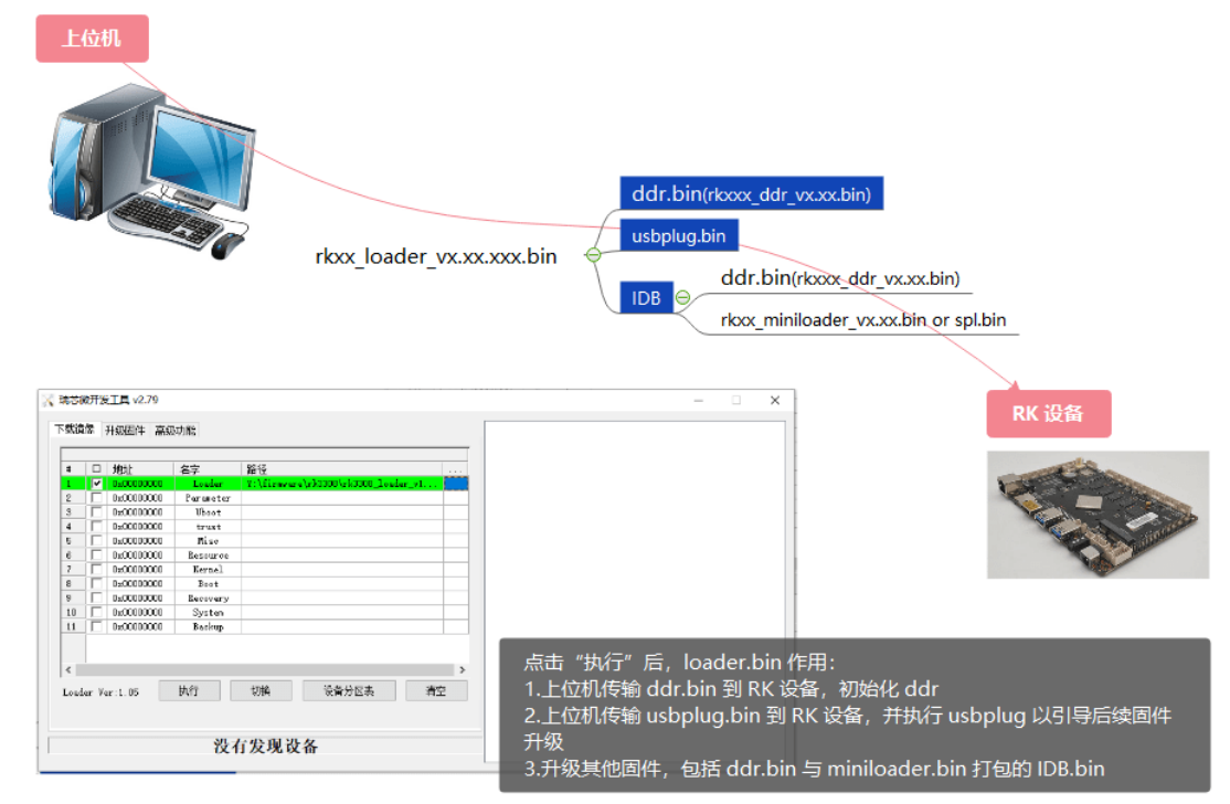
1.1 Role of Loader during programming: Chinese original figure, page 6
1.2 Flash-tool errors
Tool interface:
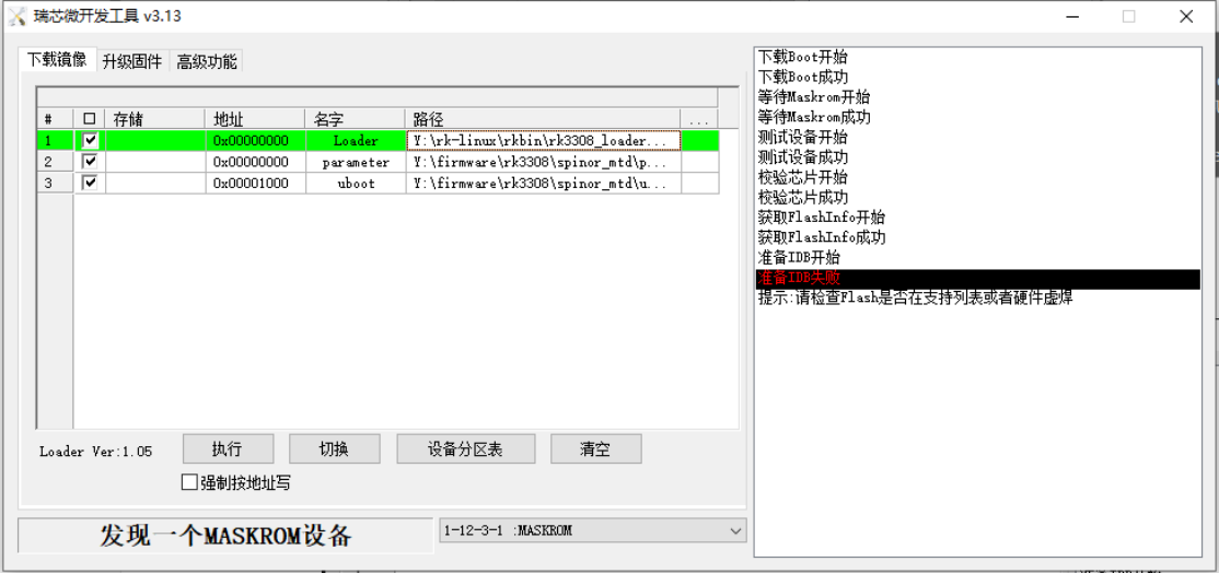
1.2 Flash-tool errors: Chinese original figure, page 6
Tool log:
18:05:40 125    Layer<1-1-2-3-1>:下载Boot成功
18:05:40 127    Layer<1-1-2-3-1>:等待Maskrom开始
18:05:40 552    Layer<1-1-2-3-1>:等待Maskrom成功
18:05:40 557    Layer<1-1-2-3-1>:测试设备开始
18:05:40 572    Layer<1-1-2-3-1>:测试设备成功
18:05:40 583    Layer<1-1-2-3-1>:校验芯⽚开始
18:05:40 592    Layer<1-1-2-3-1>:校验芯⽚成功
18:05:40 600    Layer<1-1-2-3-1>:获取FlashInfo开始
18:05:40 606    <LAYER 1-12-3-1> INFO:FlashInfo: 00 00 00 00 00 04 04 00 28 00 00
18:05:40 615    <LAYER 1-12-3-1> INFO:GetFlashInfo-->Emmc storage.
18:05:40 626    Layer<1-1-2-3-1>:获取FlashInfo成功
18:05:40 640    Layer<1-1-2-3-1>:准备IDB开始
18:05:40 645    <LAYER 1-12-3-1> ERROR:PrepareIDB-->No Found 1st Flash CS
18:05:40 663    Error:Layer<1-1-2-3-1>:准备IDB失败
18:05:40 686    Layer<1-12-3-1>: RunProc is ending, ret=0
Device UART output:
ddr.bin log:     DDR Version V1.30 20191125
ddr.bin log:     REG2C: 0x00000031, 0x00000031
ddr.bin log:     In
ddr.bin log:     451MHz
ddr.bin log:     DDR2
ddr.bin log:     Col=10 Bank=2 Row=13 Size=64MB
ddr.bin log:     msch:0
ddr.bin log:     OUT
usbplug log:     Boot1 Release Time: Dec  7 2020 11:25:17, version: 1.25
usbplug log:     chip_id:000000,0
usbplug log:     DPLL = 1300 MHz
usbplug log:     ...nandc_flash_init enter...
usbplug log:     No.1 FLASH ID:ff ff ff ff ff ff                          /* flash id 全 FF,未探测到 SLC Nand */
usbplug log:     DPLL = 1300 MHz
usbplug log:     sfc nor id: ff ff ff                                     /* flash id 全 FF,未探测到 SPI Nor */
usbplug log:     DPLL = 1300 MHz
usbplug log:     sfc_nand id: ff ff ff                                    /* flash id 全 FF,未探测到 SPI Nand */
usbplug log:     UsbBoot ...11943
usbplug log:     powerOn 664713
Analysis:
1. If ddr.bin logs are abnormal, consult a DDR engineer.
2. For parallel SLC NAND, SPI NAND or SPI NOR, an all-FF flash ID during upgrade usually indicates abnormal flash VCC, I/O voltage or soldering.
3. If the flash ID is correct but “The device not support yet!” appears, and RK SpiNor and SLC Nand SupportList lists support for the platform, the firmware is old and lacks this device support. Update the storage driver first: Redmine → FAE project → Documents → Nand flash support list → storage patch link.
4. If downloading still fails after updating, consult the RK storage engineers.
1.3 SLC NAND image does not boot
1.3.1 pin38 function is enabled
Typical programming log:
prog read s error: = 7fc00 1fff0e0 ffffffff
prog read d error: = 7fc00 0 ffffffff
phyBlk = 0x1ff die = 0 block_in_die = 0x1ff 0x80000000
prog read s error: = 7f800 1fef0e0 ffffffff
prog read d error: = 7f800 0 ffffffff
phyBlk = 0x1fe die = 0 block_in_die = 0x1fe 0xc0000000
prog read s error: = 7f400 1fdf0e0 ffffffff
prog read d error: = 7f400 0 ffffffff
Check whether flash pin38 has a function and is held at the level that disables it:
- Lock#: normally active low with a weak internal pull-up. Leave it unconnected or add an external pull-up, according to the datasheet.
- PT: normally active high with a weak internal pull-down. Leave it unconnected or add an external pull-down, according to the datasheet.
- NC: no function; leave unconnected.
1.4 SPI NAND boot stalls at SPL
The following log indicates that the SDK lacks software support for the SPI NAND device. Obtain the corresponding storage patch under Redmine → FAE project → Documents → Nand flash support list.
DDR Version V1.04 20201030
DDR, 328MHz
BW=32 Col=10 Bk=8 CS0 Row=15 CS=1 Die BW=16 Size=1024MB
change to 328MHz
change to 528MHz
change to 784MHz
change to 924MHz(final freq)
out
U-Boot SPL board init
U-Boot SPL 2017.09.g2d25c32e07-201118 #huke (Feb 26 2021 - 13:51:03)
unknown raw ID phN    # 该 log 说明 spl 驱动未⽀持该颗粒,需重新编译 spl,且核对并更新 uboot, kernel 对
应补丁
unrecognized JEDEC id bytes: ff, 98, ed
Tring to boot from MMC1
Card did not respond to voltage select!
mmc_init: -95, time 9
spl: mmc init failed with error: -95
SPL: failed to boot from all boot devices
### ERROR ### Please RESET the board ###
# Reset the board to bootrom #
1.5 Entering maskrom mode
1. With a maskrom button: hold reset, press maskrom, release reset (the tool should show maskrom), then release maskrom. The order matters to avoid abnormal behavior.
2. Without a maskrom button: the source replaces that button by shorting flash data line io0 to ground. This is a source procedure, not a board-independent wiring instruction; verify the actual schematic before any hardware operation.
1.6 Building and testing SPL separately
Change the build method. The SDK uses prebuilt SPL firmware from rkbin/bin/xx/. Therefore, the Loader generated by ./build.sh u-boot does not necessarily package the SPL just compiled. Use the following commands to package your own SPL:
cd uboot
./make.sh rv1126
./make.sh spl-s
Output under uboot: rv1126_spl_loader_vxxx.xxx.bin and uboot.img. Use this loader.bin and uboot.img.
Verify the SPL update using its log, for example: “U-Boot SPL 2017.09-gf899931b5f-201209 #ldq (Dec 10 2020 - 15:34:13)”. Check that it identifies your compiled version.
To replace the SDK SPL, copy the compiled uboot/spl/u-boot-spl.bin over ./rkbin/bin/xx/xxxx_spl_xxxx.bin.
1.7 Obtaining flash images and debug information
1.7.1 Export Image
Android tool: export firmware in maskrom mode:
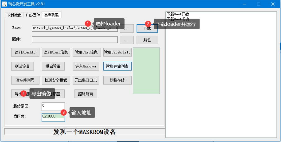
1.7.1 Export Image: Chinese original figure, page 9
Export in Loader mode: no Loader download is needed; enter the address directly in the tool to export the image.
Linux upgrade tool & Android_Console_Tool: export in maskrom mode:
db MiniloadAll.bin
rl 0x0 0x10000 Exportimage.bin
Export in Loader mode:
rl 0x0 0x10000 Exportimage.bin
Note: sector addresses use 512B per sector.
Toolskit:
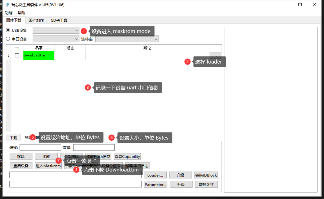
1.7.1 Export Image: Chinese original figure, page 10
1.7.2 Dump All
A special Loader ending in dump_all.bin exports flash information specific to RK FTL.
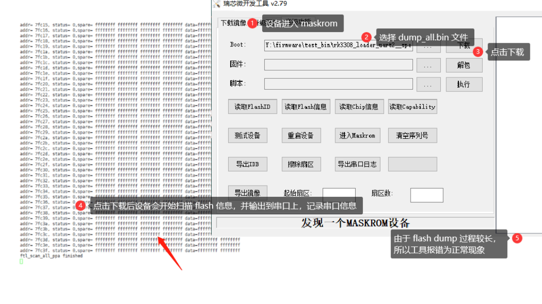
1.7.2 Dump All: Chinese original figure, page 11
1.7.3 Flash Stress Test
A special Loader ending in stress_test.bin performs a basic flash read/write/erase stress test.
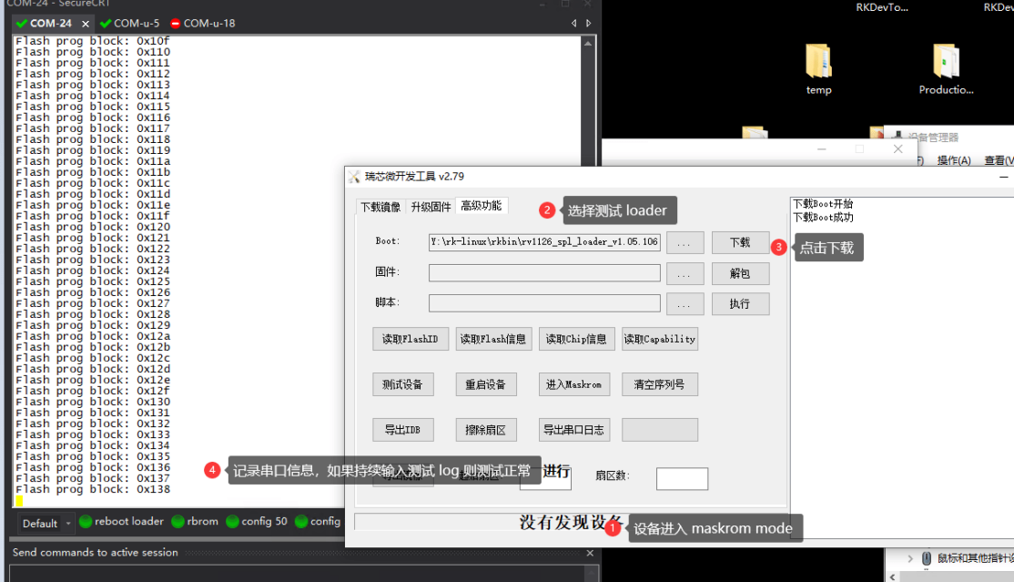
1.7.3 Flash Stress Test: Chinese original figure, page 11
1.7.4 Flash Erase All
A special Loader ending in erase_all.bin erases all flash data.
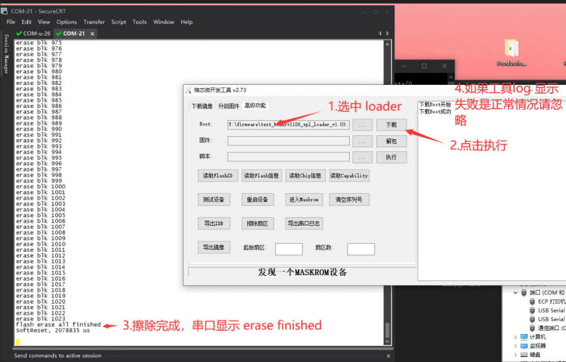
1.7.4 Flash Erase All: Chinese original figure, page 12
2. Filesystem issues
2.1 UBIFS partition not fully erased before upgrade
Before upgrading an image using UBIFS, erase the entire target partition, or preferably use ubiupdatevol to update it. Typical errors:
...
[    4.452318] ubi0: attaching mtd5
[    4.685258] ubi0 error: ubi_attach: bad image sequence number 1251817256 in PEB 543, expected
1051610977
[    4.685317] Erase counter header dump:
[    4.685334]  magic          0x55424923
[    4.685348]  version        1
[    4.685361]  ec             1
[    4.685374]  vid_hdr_offset 2048
[    4.685386]  data_offset    4096
[    4.685400]  image_seq      1251817256
[    4.685413]  hdr_crc        0x88225c8a
[    4.685426] erase counter header hexdump:
[    4.685753] ubi0 error: ubi_attach_mtd_dev: failed to attach mtd5, error -22
[    4.685814] UBI error: cannot attach mtd5
...
[    4.695772] ALSA device list:
[    4.695796]   #7: Loopback 1
[    4.696063] VFS: Cannot open root device "ubi0:rootfs" or unknown-block(0,0): error -19
[    4.696091] Please append a correct "root=" boot option; here are the available partitions:
...
Recommended tool versions:
Windows rkdevtool v2.79 or later; Linux_Upgrade_Tool_v1.59 or later.
2.2 UBIFS image does not match flash geometry
Check that flash-related mkfs options such as -e and -m match the actual device. Otherwise the booted system cannot locate UBI information. Typical errors — case 1:
...
[    1.319729] ubi0: attaching mtd3
[    1.549286] ubi0: scanning is finished
[    1.549326] ubi0 error: ubi_read_volume_table: the layout volume was not found
[    1.549464] ubi0 error: ubi_attach_mtd_dev: failed to attach mtd3, error -22
[    1.549499] UBI error: cannot attach mtd3
...
[    1.563848]   #7: Loopback 1
[    1.564173] UBIFS error (pid: 1): cannot open "ubi0:rootfs", error -19VFS: Cannot open root device
"ubi0:rootfs" or unknown-block(0,0): error -19
...
Case 2: actual page size 4KB; image page size 2KB.
[    0.517603] ubi0 error: validate_ec_hdr: bad VID header offset 2048, expected 4096
[    0.517618] ubi0 error: validate_ec_hdr: bad EC header
[    0.517626] Erase counter header dump:
[    0.517634]  magic          0x55424923
[    0.517639]  version        1
[    0.517645]  ec             0
[    0.517650]  vid_hdr_offset 2048
[    0.517657]  data_offset    4096
[    0.517664]  image_seq      2053699779
[    0.517672]  hdr_crc        0x2416c7f2
[    0.517679] erase counter header hexdump:
[    0.517701] CPU: 0 PID: 1 Comm: swapper/0 Not tainted 4.19.111 #2
Case 3: actual page size 2KB; image page size 4KB.
[    1.678775] ubi0: attaching mtd6
[    1.679040] ubi0 error: validate_ec_hdr: bad VID header offset 4096, expected 2048
[    1.679054] ubi0 error: validate_ec_hdr: bad EC header
[    1.679068] Erase counter header dump:
[    1.679079]  magic          0x55424923
[    1.679090]  version        1
[    1.679101]  ec             0
[    1.679110]  vid_hdr_offset 4096
[    1.679120]  data_offset    8192
[    1.679131]  image_seq      362848614
[    1.679141]  hdr_crc        0x9438b345
[    1.679157] erase counter header hexdump:
[    1.679195] CPU: 0 PID: 1 Comm: swapper/0 Not tainted 4.19.172 #8
[    1.679207] Hardware name: Rockchip RK3566 For 360 X200 (DT)
[    1.679220] Call trace:
[    1.679238]  dump_backtrace+0x0/0x178
2.3 UBIFS image exceeds partition size
Reduce the image or enlarge the partition. Typical errors:
[    2.121208] ubi0 error: vtbl_check: too large reserved_pebs 824, good PEBs 767
[    2.121295] ubi0 error: vtbl_check: volume table check failed: record 0, error 9
[    2.121338] Volume table record 0 dump:
[    2.121375]  reserved_pebs   824
[    2.121412]  alignment       1
[    2.121449]  data_pad        0
[    2.121529]  vol_type        1
[    2.121568]  upd_marker      0
[    2.121605]  name_len        6
[    2.121642]  name            rootfs
[    2.121680]  crc             0x9ab0c6a3
[    2.122162] ubi0 error: ubi_attach_mtd_dev: failed to attach mtd3, error -22
[    2.122278] UBI error: cannot attach mtd3
2.4 UBIFS firmware tail is corrupted
This issue requires further investigation. Typical errors:
[    1.867789] ALSA device list:
[    1.867830]   #7: Loopback 1
[    1.916907] UBIFS (ubi0:0): UBIFS: mounted UBI device 0, volume 0, name "rootfs", R/O mode
[    1.917010] UBIFS (ubi0:0): LEB size: 126976 bytes (124 KiB), min./max. I/O unit sizes: 2048 bytes/2048
bytes
[    1.917061] UBIFS (ubi0:0): FS size: 103231488 bytes (98 MiB, 813 LEBs), journal size 9023488 bytes (8
MiB, 72 LEBs)
[    1.917106] UBIFS (ubi0:0): reserved for root: 0 bytes (0 KiB)
[    1.917155] UBIFS (ubi0:0): media format: w4/r0 (latest is w5/r0), UUID 1C1DDBB4-77E6-4AA9-855F-
ED8F10EB5916, small LPT model
2.5 UBIFS journal reservation is too large
UBIFS is a journaling filesystem. An excessively large journal in a small partition may prevent mounting. Consider adjusting this parameter:
-j, --jrn-size=SIZE journal size
Typical error messages:
[root@RV1126_RV1109:/]# mount -t ubifs /dev/ubi2_0 /record/
[   65.788339] UBIFS error (ubi2:0 pid 890): ubifs_read_superblock: mount: mounting /dev/ubi2_0 on
/record/ failed: Invalid argument
too large journal size (8388608 bytes), only 3555328 bytes available in the main area
[   65.78[root@RV1126_RV1109:/]# 8394] UBIFS error (ubi2:0 pid 890): ubifs_read_superblock: bad
superblock, error 1
[   65.788413]  magic          0x6101831
[   65.788434]  crc            0x663d9574
[   65.788455]  node_type      6 (superblock node)
[   65.788475]  group_type     0 (no node group)
[   65.788493]  sqnum          1
[   65.788512]  len            4096
[   65.788531]  key_hash       0 (R5)
[   65.788620]  key_fmt        0 (simple)
[   65.788639]  flags          0x4
[   65.788660]  big_lpt        0
[   65.788684]  space_fixup    1
[   65.788706]  min_io_size    2048
[   65.788728]  leb_size       126976
[   65.788755]  leb_cnt        39
[   65.788773]  max_leb_cnt    2048
[   65.788786]  max_bud_bytes  8388608
[   65.788799]  log_lebs       5
[   65.788812]  lpt_lebs       2
[   65.788826]  orph_lebs      1
[   65.788838]  jhead_cnt      1
[   65.788851]  fanout         8
[   65.788864]  lsave_cnt      256
[   65.788877]  default_compr  1
[   65.788890]  rp_size        0
[   65.788905]  rp_uid         0
[   65.788918]  rp_gid         0
[   65.788931]  fmt_version    4
[   65.788945]  time_gran      1000000000
[   65.788961]  UUID           DBC08BA0-15FE-49BD-BC47-8A9200F1D625
2.6 SquashFS on UBI block lacks ZLIB support
Enable CONFIG_SQUASHFS_ZLIB. Typical errors:
[    4.564088] rockchip-mipi-dphy-rx: No link between dphy and sensor
[    4.564102] rkisp0: update sensor failed
[    4.564181] ALSA device list:
[    4.564191]   #0: rockchip,rk809-codec
[    4.564200]   #7: Loopback 1
[    4.566057] squashfs: SQUASHFS error: Filesystem uses "zlib" compression. This is not supported
[    4.566158] List of all partitions:
[    4.566179] fd00           31792 ubiblock0_0
[    4.566181]  (driver?)
[    4.566196] No filesystem could mount root, tried:
[    4.566197]  squashfs
[    4.566206]
[    4.566225] Kernel panic - not syncing: VFS: Unable to mount root fs on unknown-block(253,0)
[    4.570008] CPU: 3 PID: 1 Comm: swapper/0 Not tainted 4.19.149 #3
[    4.570547] Hardware name: Generic DT based system
[    4.570993] [<b010f47c>] (unwind_backtrace) from [<b010b9a8>] (show_stack+0x10/0x14)
[    4.571677] [<b010b9a8>] (show_stack) from [<b0827b68>] (dump_stack+0x90/0xa4)
[    4.572317] [<b0827b68>] (dump_stack) from [<b01264fc>] (panic+0x114/0x2a0)
[    4.572962] [<b01264fc>] (panic) from [<b0c013a8>] (mount_block_root+0x2a4/0x2f4)
[    4.573629] [<b0c013a8>] (mount_block_root) from [<b0c015d0>] (prepare_namespace+0x150/0x1
2.7 UBIFS image cannot mount on an undersized empty partition
Minimum UBIFS partition:
Minimum block num = 4(固定预留) + B + 17  /* B - 为坏块替换预留的 f1ash blocks,与 ubiattach - b 参数相
关 */
Determine the value from the ubiattach log, for example:
ubi4: available PEBs: 7, total reserved PEBs: 24, PEBs reserved for bad PEB handling: 20 /* B = 20 */
If available PEBs + total reserved PEBs for the partition is less than Minimum block num, mounting reports:
mount: mounting /dev/ubi4_0 on userdata failed: Invalid argument
2.8 LZO or ZLIB for UBIFS
RK SDK uses LZO compression by default. In one source example, 103M compresses to 80M; ZLIB has a similar ratio. Use SquashFS if a higher compression ratio is required.
2.9 Expanded UBIFS image exceeds partition size
UBIFS images normally use autoresize. Specifying the image size in the configuration used by the following command may cause the expanded image to exceed the partition:
ubinize -o ubi.img -m 2048 -p 128kiB -O 2048 ubinize.cfg

//ubinize.cfg
[ubifs]
  mode=ubi
  image=ubifs.img
  vol_id=0
  vol_size=192MB                // ⽆需指定⼤⼩,使⽤ autoresize 特性
  vol_type=dynamic
  vol_name=rootfs
  vol_flags=autoresize
Typical error messages:
[    2.345243] ubi0: attaching mtd2
[    2.415631] ubi0: scanning is finished
[    2.419742] ubi0 error: vtbl_check: too large reserved_pebs 1586, good PEBs 699
[    2.419785] ubi0 error: vtbl_check: volume table check failed: record 0, error 9
[    2.419792] Volume table record 0 dump:
[    2.419798]  reserved_pebs   1586
[    2.419803]  alignment       1
[    2.419808]  data_pad        0
[    2.419813]  vol_type        1
[    2.419818]  upd_marker      0
[    2.419823]  name_len        6
[    2.419829]  name            rootfs
[    2.419835]  crc             0x23e79a61
[    2.420000] ubi0 error: ubi_attach_mtd_dev: failed to attach mtd2, error -22
[    2.420024] UBI error: cannot attach mtd2
UBIFS fails to mount after upgrading a modified GPT in Loader mode. In the RK SDK MTD boot scheme, a Loader-mode upgrade with changed GPT writes the target firmware using the old bad-block mapping established when U-Boot started. Loader-mode upgrades therefore support only unchanged GPT layouts. Otherwise switch to maskrom mode. Typical logs after an incorrect upgrade — case 1:
[    0.659432] ubi0: attaching mtd3
[    1.264467] ubi0: scanning is finished
[    1.271151] ubi0 warning: ubi_read_volume_table: static volume 0 misses 1 LEBs - corrupted
[    1.302342] ubi0: volume 0 ("rootfs") re-sized from 613 to 636 LEBs
[    1.303492] ubi0: attached mtd3 (name "rootfs", size 85 MiB)
[    1.303526] ubi0: PEB size: 131072 bytes (128 KiB), LEB size: 126976 bytes
[    1.303533] ubi0: min./max. I/O unit sizes: 2048/2048, sub-page size 2048
[    1.303540] ubi0: VID header offset: 2048 (aligned 2048), data offset: 4096
[    1.303547] ubi0: good PEBs: 677, bad PEBs: 3, corrupted PEBs: 0
[    1.303559] ubi0: user volume: 1, internal volumes: 1, max. volumes count: 128
[    1.303568] ubi0: max/mean erase counter: 1/0, WL threshold: 4096, image sequence number:
980761742
[    1.303578] ubi0: available PEBs: 0, total reserved PEBs: 677, PEBs reserved for bad PEB handling: 37
[    1.303599] ubi0: background thread "ubi_bgt0d" started, PID 80
Case 2:
[11:34:08:931][    0.661124] ubi0: attaching mtd6
[11:34:08:931][    0.662524] ubi0 error: ubi_attach: bad image sequence number 67638577 in PEB 1,
expected 980761742
[11:34:08:931][    0.662571] Erase counter header dump:
[11:34:08:931][    0.662578]  magic          0x55424923
[11:34:08:931][    0.662584]  version        1
[11:34:08:931][    0.662590]  ec             0
[11:34:08:931][    0.662595]  vid_hdr_offset 2048
[11:34:08:931][    0.662601]  data_offset    4096
[11:34:08:931][    0.662606]  image_seq      67638577
[11:34:08:947][    0.662611]  hdr_crc        0x3a381cee
[11:34:08:947][    0.662616] erase counter header hexdump:
[11:34:08:949][    0.662645] ubi0 error: ubi_attach_mtd_dev: failed to attach mtd6, error -22
[11:34:08:949][    0.662675] UBI error: cannot attach mtd6
[11:34:08:949][    0.662691] UBI: block: can't open volume on ubi0_-1, err=-19
2.10 UBIFS support on SPI NOR
Important: SPI NOR is recommended to use JFFS2 as its writable filesystem. Kernel configuration:
CONFIG_MTD_SPI_NOR_USE_4K_SECTORS = n
Create the image:
mkfs.ubifs -r data/ -m 1 -e 65408 -c 62 userdata.ubifs
ubinize -o ubi.img -m 1 -p 64KiB -O 64 ubinize_userdata.cfg

(cid:0)(cid:0)(cid:0)(cid:0)(cid:0)(cid:0)(cid:0)  ubifs cat ubinize_userdata.cfg
[userdata-volume]
mode=ubi
image=userdata.ubifs
vol_id=0
vol_size=2MiB
vol_type=dynamic
vol_name=userdata
vol_flags=autoresize
Explanation: 4KB erases cannot be supported because c->leb_size < UBIFS_MIN_LEB_SZ. UBIFS_MIN_LEB_SZ is 15KB, while leb_size depends on MTD properties.
2.11 Formatting-based recovery for damaged UBIFS userdata
Suggested userdata low-level-format recovery scheme:
- Keep frequently written files in one partition.
- Do not store unrecoverable files in that partition.
- If mounting fails, format the partition and regenerate essential data so the device can continue running.
Reference formatting commands:
ubidetach -m 7
ubiformat -y /dev/mtd7
ubiattach /dev/ubi_ctrl -m 7 -d 7
ubimkvol /dev/ubi7 -N userdata -m
mount -t ubifs /dev/ubi7_0 /userdata
2.12 UBIFS failure due to incorrect vol_name
Abnormal log:
[    6.278922] VFS: Cannot open root device "ubi0:rootfs" or unknown-block(0,0): error -19
[    6.278943] Please append a correct "root=" boot option; here are the available partitions:
Explanation: vol_name of the rootfs partition was not defined as rootfs.
2.13 Long boot time for SquashFS on UBI
For SPI NAND products that prioritize filesystem reliability over boot time, the source recommends static volume when creating the UBI image for SquashFS, so startup verifies filesystem integrity. The RK SDK described in the source enables this by default. If changing it, maintain data-integrity verification yourself.
Problem: customer and local source tests found that SquashFS on SPI NAND UBI images takes about one second per 10MB to load; a 50MB UBI partition can take five seconds. These are source tests, not ArmSoM measurements.
Analysis: UBI images can use static or dynamic volumes. A static volume is read-only and its startup mount checks the CRC of the whole image; it is suitable for additional verification of images without a filesystem, such as kernel/initramdisk. A dynamic volume supports reading and writing.
UBIFS documentation asks why a dynamic volume is faster to access than a static volume of the same size. Static UBI volumes were originally intended for data blobs such as configuration files. They protect stored data with CRC-32 and know its actual length. For example, a 254KiB static volume /dev/ubi0_1 made of two 127KiB LEBs and containing a 200KiB file returns exactly 200KiB when the entire device is read. A dynamic volume returns 254KiB. Static volumes thus simplify storing blobs. They are slower because UBI must verify the CRC-32 checksum. Using static volumes with read-only UBIFS is not recommended: UBIFS already protects its stored information with CRC-32, so another static-volume check only slows mounting.
The source therefore advises against extra static-volume CRC checking for UBIFS, which already has its own CRC protection. By the same reasoning:
Because SquashFS does not verify integrity of the entire image at startup, the source recommends static volume for its UBI image.
Source tests:
TEST01 — boot time: RV1106 with SPI NAND and a dynamic-volume UBI image containing SquashFS booted normally. Startup added no data-write overhead (read-only), and removing redundant CRC checks restored normal loading time.
TEST02 — SquashFS compression/decompression without static integrity checks: create a SquashFS UBI image with dynamic volume, locate a target file and alter some bytes, program the image, then read it after boot. File data was indeed damaged. The source concludes “ubifs has no integrity check”; this name conflicts with the SquashFS test context and is preserved as a source ambiguity, not endorsed.
TEST03 — adding static verification: create a SquashFS UBI image with static volume, alter bytes in a target file, program it, then read it after boot. UBI scans the image at startup and prints the following errors:
[    6.358100] ubi0 warning: ubi_eba_read_leb: CRC error: calculated 0xae6dc941, must be 0xf62e2df5
[    6.358212] ubi0 warning: ubi_open_volume: volume 0 on UBI device 0 is corrupted
Appendix: changes from static to dynamic:
[rootfs-volume]
mode=ubi
image=rootfs.squashfs
vol_id=0
vol_size=60MiB
vol_type=static
vol_name=rootfs
vol_alignment=1
vol_flags=autoresize
Change to:
[rootfs-volume]
mode=ubi
image=rootfs.squashfs
vol_id=0
vol_size=60MiB
vol_type=dynamic
vol_name=rootfs
vol_alignment=1
vol_flags=autoresize
2.14 UBIFS 4KB pages consume more overhead than 2KB pages in equal-sized partitions
This is expected: UBIFS reserves a fixed number of flash blocks for its algorithms. Thus, for equal partition capacity, devices with 4KB pages consume more overhead space.
2.15 UBIFS df reports little space
See the UBIFS community section “Why does df report too little free space?”. UBIFS must account for overhead, compression and algorithms; it cannot accurately predict storable data capacity and estimates conservatively. df therefore appears to report less space, while actual transferred data may exceed that value.
2.16 JFFS2 mounts slowly
JFFS2 performs garbage collection during startup. This is inherent behavior; even ls can be slow, and performance degrades with use.
2.17 JFFS2 partition not erased
Update the upgrade tool. Newer versions recognize JFFS2 images and erase the partition before upgrading:
mount -t jffs2 /dev/block/by-name/userdata /userdata
[    2.232850] jffs2: Empty flash at 0x002c1204 ends at 0x002c2000
[    2.232931] jffs2: CLEANMARKER node found at 0x002c2000, not first node in block (0x002c0000)
[    2.233065] jffs2: Empty flash at 0x002c200c ends at 0x002c3000
[    2.233075] jffs2: CLEANMARKER node found at 0x002c3000, not first node in block (0x002c0000)
[    2.233428] jffs2: Empty flash at 0x002c300c ends at 0x002c4000
2.18 JFFS2 conflicts with SPI NOR 4K erases
JFFS2 requires at least 8KB erase alignment, whereas the SPI NOR kernel framework supports 4KB or 64KB alignment. Therefore, to use JFFS2, do not enable CONFIG_MTD_SPI_NOR_USE_4K_SECTORS; use 64KB erase alignment.
2.19 YAFFS is not recommended
The source strongly discourages YAFFS, stating that the open-source community no longer maintains it, and recommends moving to UBIFS. This is the source recommendation, not a newly verified maintenance-status claim.
2.20 RK solution does not support YAFFS2
Reasons:
- RK SPI NAND support for UBIFS is relatively complete; UBIFS is recommended.
- YAFFS2 performs OOB operations and writes pages multiple times; current source tests found incompatibility.
For customer-developed YAFFS support, the source lists controller drivers for independent development:
- Kernel 4.19 and earlier: drivers/rfkash/ (source spelling; verify before use).
- Kernel 5.10: drivers/spi/spi-rockchip-sfc.c.
2.21 EXT cannot be used with this NAND solution
EXT has no FTL suitable for Raw NAND and lacks wear leveling, data refresh, bad-block management and other algorithms essential for NAND devices.
2.22 EXT2 support on SPI NOR
Warning: no wear leveling; use cautiously. Erase alignment is 4KB.
Enable CONFIG_MTD_SPI_NOR_USE_4K_SECTORS. SPI NOR supports ext2 by mounting the partition through the mtdblock device. Avoid frequent filesystem writes. The source gives a typical SPI NOR P/E (erase/write) endurance of 100K cycles; assess the actual product lifetime independently.
2.23 EXT2 lacks discard, reducing later read/write performance
The source states that ext2 lacks discard support, including the Linux versions it considered. If all flash space has been used, deleting files changes only inodes and does not notify the underlying storage to release space. The underlying occupied space therefore cannot be reclaimed that way.
Recommendations: reuse files, avoid frequent creation and avoid large files continually filling all space. If unavoidable, consider periodically formatting the disk: mkfs.ext2 invokes discard to release space. Alternatively migrate to ext4 and mount with discard. These are source-version statements; verify behavior for the actual filesystem tools, driver and kernel before adapting.
2.24 SquashFS compression methods and efficiency
The following is only a preliminary reference; compression efficiency depends on data type and other factors:
| Method | Ratio | Compression MB/s | Decompression MB/s |
|---|---|---|---|
| gzip | 2.92 | 15 | 128 |
| lzo | 2.64 | 9.5 | 217 |
| lz4 | 2.12 | 94 | 218 |
| xz | 3.43 | 5.5 | 35 |
| xz 256 KB | 3.53 | 5.4 | 40 |
| zstd 1 | 2.71 | 96 | 210 |
| zstd 5 | 2.93 | 69 | 198 |
| zstd 10 | 3.01 | 41 | 225 |
| zstd 15 | 3.13 | 11.4 | 224 |
| zstd 16 256 KB | 3.24 | 8.1 | 210 |
Data source: squashfs: Add zstd support.
3. EMMC issues
3.1 Intermittent EMMC communication errors in the kernel
Several causes are possible. Cases encountered in the source include:
VDDI external capacitance too small. The EMMC controller requires an operating voltage of about 1.2V, generally derived from VCCQ through an LDO. The capacitor on VDDI filters this 1.2V supply. Most EMMC packages already connect a small internal capacitor to VDDI, but different manufacturers and models have different controllers and internal capacitor values, so external VDDI capacitance requirements differ. Typical source requirements:
| Operating mode | VDDI capacitance |
|---|---|
| HS400 | 1 - 2.2uF (some devices 2-4.7uF) |
| Non-HS400 modes | 0.1uF - 2.2uF |
An undersized or failed external VDDI capacitor can explain why device A works but replacing it with device B produces intermittent communication errors.
Suggested VDDI capacitance values (use the upper limit or close to it):
| Platform | Operating mode | VDDI capacitance |
|---|---|---|
| RK3399 | HS400 | 2.2uF |
| Other platforms | HS200,DDR50, SDR 50 | 1uF |
Missing or undersized host-side VCCQ capacitor. EMMC 5.1 reads and writes very quickly; higher capacities generally write faster. VCC and VCCQ transient current may exceed 400mA (about 200mA for most devices). Without sufficient host-side VCCQ capacitance, VCCQ may collapse at startup or during use, causing EMMC read errors.
ESD devices on EMMC DATA lines. SD cards need ESD devices, but EMMC is soldered to the board and not hot-plugged, so the source says additional ESD devices are unnecessary. Excessive ESD capacitance can severely distort signals and cause HS400/HS200 errors.
EMMC CLK/CMD too close to high-speed signals such as HDMI. Interference can cause communication errors.
Unequal EMMC trace lengths and large series resistance on CMD/CLK. HS200 and HS400 both use a 200MHz clock. These conditions narrow the valid read-data window, making errors more likely as voltage and temperature change.
3.2 EMMC missing or verification fails during upgrade
Several causes are possible. Incorrect VCCQ selection: VCCQ supports 1.8V and 3.3V, and the host I/O must be configured accordingly. A selection I/O is generally tied to VCC or ground; consult the schematic.
| VCCQ voltage | Host I/O mode | Result |
|---|---|---|
| 1.8V | 1.8V | Normal |
| 1.8V | 3.3V | Does not work |
| 3.3V | 1.8V | May work at low speed; errors at high speed |
| 3.3V | 3.3V | Normal |
Insufficient VDDI capacitance: see the earlier VDDI discussion (the source cross-reference says “1.1”).
EMMC soldering or device damage: some DNU/NC balls must remain reserved and may be internally connected to ground or VCCQ. Connecting them to other I/O in the PCB can short data or power on certain models. Poor manual soldering can prevent detection. Excessive reflow temperature or moisture in the component can damage it and prevent host detection.
3.3 EMMC damage or firmware loss after use
Main source cases:
EMMC device faults generally fall into two categories:
1. An individual device develops data corruption after use, for example due to bad blocks; reprogramming host firmware may repair it. If EMMC internal firmware fails, the device must be replaced. The source reports a failure probability generally below one in a thousand, not an ArmSoM-measured rate.
2. EMMC firmware defects can cause widespread data loss or firmware failure, with a much higher failure rate. This requires FFU to update the EMMC firmware or device reinitialization.
Endurance exhausted by excessive system writes: poor application/Android design or configuration can generate excessive small random log writes. EMMC write amplification can be large: a 1KB log write may require a 16KB page write, plus filesystem updates, totaling three writes or 48KB in the source example.
EMMC 5.1 EXT CSD exposes endurance information: DEVICE_LIFE_TIME_EST_TYP_B [269], PRE_EOL_INFO [267], and DEVICE_LIFE_TIME_EST_TYP_B [268]. The duplicated TYPE_B name is the source spelling, not silently corrected. Read EXT CSD as follows:
1. Read it using mmc-utils; consult the utility help.
2. In a Linux console, cat the EMMC ext_csd node. Its location varies by system; locate it with find ext_csd as described in the source.
cat /sys/kernel/debug/mmc0/mmc0:0001/ext_csd
3. In maskrom upgrade mode, download a debug Loader whose filename contains dump_ext_csd. The serial port prints EXT CSD information.
Linux upgrade tool & Android_Console_Tool:
db xxxloaderxxx.bin
Android tool:
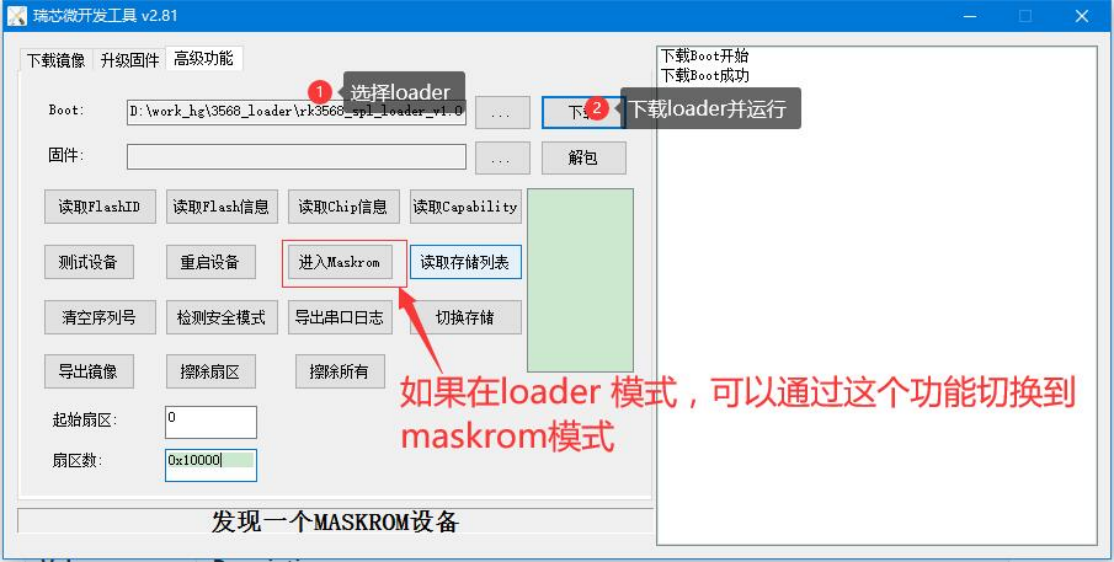
3.3 EMMC damage or firmware loss after use: Chinese original figure, page 25
EXT CSD endurance information:
DEVICE_LIFE_TIME_EST_TYP_B [269] and DEVICE_LIFE_TIME_EST_TYP_B [268] record EMMC program/erase endurance; see the table. Both identifiers retain the source spelling.
| Value | Description |
|---|---|
| 0x00 | Not defined |
| 0x01 | 0% - 10% device life time used |
| 0x02 | 10% -20% device life time used |
| 0x03 | 20% -30% device life time used |
| 0x04 | 30% - 40% device life time used |
| 0x05 | 40% - 50% device life time used |
| 0x06 | 50% - 60% device life time used |
| 0x07 | 60% - 70% device life time used |
| 0x08 | 70% - 80% device life time used |
| 0x09 | 80% - 90% device life time used |
| 0x0A | 90% - 100% device life time used |
| 0x0B | Exceeded its maximum estimated device life time |
| Others | Reserved |
PRE_EOL_INFO [267] indicates whether EMMC reserved blocks are exhausted; see the table:
| Value | Pre-EOL Info. | Description |
|---|---|---|
| 0x00 | Not Defined | |
| 0x01 | Normal | Normal |
| 0x02 | Warning | Consumed 80% of reserved block |
| 0x03 | Urgent | |
| 0x04 ~ 0xFF | Reserved |
Power loss during OTA: the source says Android releases after 7.1 directly update system partition blocks rather than files. Unexpected power loss during OTA may therefore corrupt the system partition.
3.4 EMMC remains in maskrom after upgrading
Poor EMMC soldering or PCB problems: BOOTROM boots in 8-bit mode. If any EMMC D1–D7 line is not connected correctly, 8-bit mode cannot operate. Poor soldering:
If only individual samples fail, poor soldering is the usual cause.
PCB issue: if all samples fail, suspect the PCB, for example data traces routed through RFU or DNU balls.
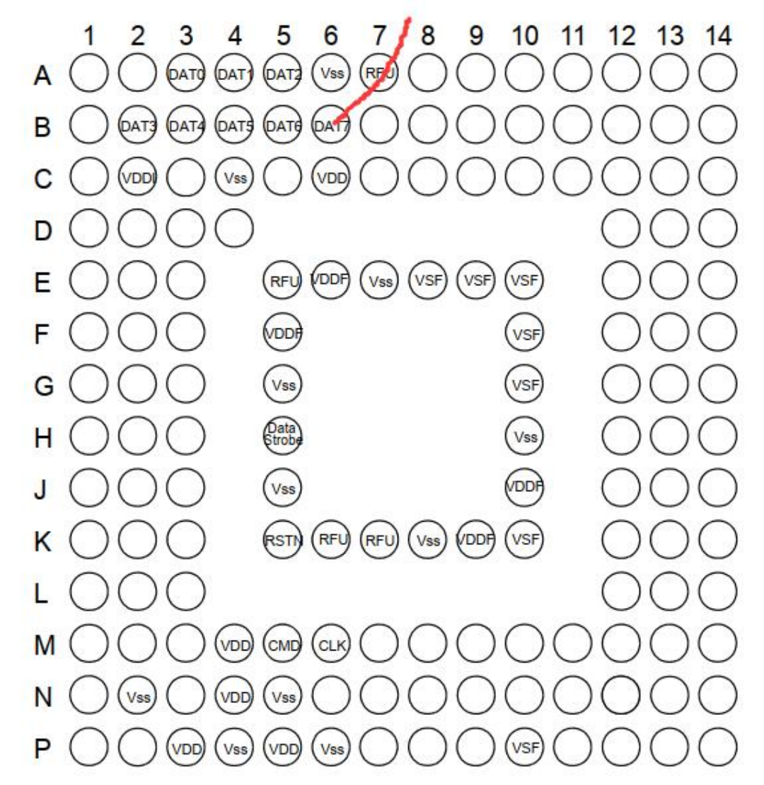
3.4 EMMC remains in maskrom after upgrading: Chinese original figure, page 27
Missing or misplaced uboot/trust: if either image is absent or programmed at the wrong offset, Miniloader cannot start U-Boot and returns to maskrom upgrade mode. Serial logs show Miniloader starting and then rebooting.
4. Flash issues
4.1 Flash read/write rates
General test (near optimal): use dd to test at least 10MB of space.
| Device type | Test environment | Sequential read | Sequential write |
|---|---|---|---|
| SLC Nand | Linux | 16MB/s(IO 30MHz) | 4MB/s(IO 30MHz) |
| SPI Nand | Linux | 10.8MB/s (IO 80MHz) | 4.0 MB/s (IO 48MHz) |
| SPI Nor | Linux | 24.0MB/s(IO 80MHz) | 100~200 KB/s(IO 48MHz) |
| SPI Nor | RTT | 35MB/s (IO 80MHz) | 100~200KB/s(IO 80MHz) |
| Device type | Test environment | Random 4K read | Random 4K write |
|---|---|---|---|
| SPI Nor | RKOS | 13MB/s (IO 80MHz) | 100~200 KB/s(IO 48MHz) |
Special write-rate test 1 (near saturation), source environment:
- RK3308_V10_EVB.
- Kernel 4.4, 64-bit.
- User partition: 352MB.
- Flash capacity: 512MB.
Test case:
Sub Main
    while (1)
        crt.Screen.Send "rm /userdata/test && sync"
        crt.Screen.Send chr (13)
        crt.Sleep 2000
        crt.Screen.Send "time dd if=/dev/zero of=/userdata/test bs=1M count=350 && sync"
        crt.Screen.Send chr (13)
        crt.Screen.waitForString "real"
        crt.Sleep 2000
    wend
End Sub
Source conclusion: half an hour of testing gave a fully loaded write rate of 2.0 MB/s. This is not an ArmSoM measurement.
4.2 Flash write protection
Flash write protection:
- Software protection is usually supported by devices, but implementations vary.
- Some devices support the hardware wp# pin. RK cannot control that pin directly; if required, use GPIO control.
The RK storage scheme described in the source adds no write-protection handling: storage uses a unified read/write interface, a complete read/write transaction should not theoretically be triggered by an abnormal signal, and protection schemes vary considerably between devices.
4.3 Software chip selection is incompatible with two-die flash
The current software framework does not support a stacked-die device containing two flash devices of the same type when chip selection is implemented in software.
4.4 Typical kernel logs after failed storage initialization
If storage initialization fails, corresponding MTD partitions are not created. The system nevertheless continues until it tries to mount a non-ramdisk root filesystem, then stops with messages such as “waiting for root……”.
4.5 Ensuring writes to storage device nodes reach media
The source suggests adding O_SYNC or O_DIRECT to fopen, or calling fsync after writing. For dd image upgrades it recommends iflag=nocache and oflag=direct. The source names fopen although these flags normally belong to open; the inconsistency is retained for verification, not silently rewritten.
4.6 Replacing flash devices
T/A and S/A in the support list: RK SPI-flash controller IP is compatible across platforms. T/A denotes a sample validated on the storage-validation platform; S/A denotes a compatible platform. The source permits products to use flash with T/A or S/A support.
New NAND materials: RK validates basic functionality and stability of submitted samples on the test platform. Actual products should undergo additional flash tests, including signal consistency before/after device replacement and compliance with the device specification, plus unexpected-power-loss robustness. See Rockchip_Developer_Guide_Linux_Flash_Open_Source_Solution_CN.pdf.
4.7 Diagnosing TFTP firmware download/programming failures
Initial diagnosis: calculate and compare md5sum at each stage:
1. After creating the upgrade image. 2. After downloading through TFTP; a mismatch suggests network or DRAM problems. 3. Read back online after programming flash and calculate md5sum; a mismatch suggests flash malfunction. Reduce flash speed or switch to single-line transfers to investigate. 4. Enter maskrom, read back the image and calculate md5sum; compare with the online read-back result.
If flash is initially suspected:
If reducing speed or using a single line helps, measure signal quality and flash-supply stability, then adjust hardware and check whether default settings work. If it does not help, consult the RK storage software engineer.
4.8 U-Boot MTD versus mtd_block interfaces

4.8 U-Boot MTD versus mtd_block interfaces: Chinese original figure, page 30
Program/erase granularity mismatch: NOR and NAND have different minimum erase and program units. Writing 256B inside a NOR 4K sector requires erasing 4K, so the other (4KB - 256B) bytes must be saved beforehand and restored.
MTD versus block interfaces:
- MTD requires the upper layer to manage program/erase operations.
- Block interfaces abstract a minimum logical read/write sector; accessing one sector does not affect others, because granularity mismatch is handled internally.
- Linux mtdblock exposes 512B logical sectors and maintains the program/erase relationship so writing one 512B sector handles the mismatch.
RK SDK U-Boot implements corresponding logic based on Linux.
4.9 Flash stress failures at low temperature
First measure whether VCCIO Flash sel pull-up/pull-down levels are abnormal at low temperature.
4.10 Accidental maskrom-button contact disrupts transfers
Place the maskrom button where it is not easily touched, so accidental operation does not disrupt data transfers.
5. Flash-controller issues
5.1 FSPI clock duty cycle is not 50%
The output clock is divided from a particular PLL in the clock tree. Odd division may not produce a 50% duty cycle, making timing marginal at the peripheral maximum rate. Even division produces a 50% duty cycle.
5.2 FSPI is not general-purpose SPI; only SPI memory is supported
FSPI (formerly SFC) supports only SPI-memory timing: cmd + addr (optional) + dummy (optional) + data (optional). In particular, it does not support starting input immediately after CS assertion. Check the timing carefully. For external peripherals such as an FPGA, assess whether the protocol fits these requirements. Kernel-driver reference: spi-rockchip-sfc.c.
5.3 FSPI setup/hold timing is not measured
FSPI reads in U-Boot and kernel use four-line transfers by default. If the configured rate is identical, host read-sampling setup/hold requirements are theoretically identical.
Background:
1. FSPI read-sampling basics. FSPI uses SPI mode 0: CPOL clock idle low, CPHA sampling on the first edge. Read sampling is then shifted by half a cycle, to the falling edge.
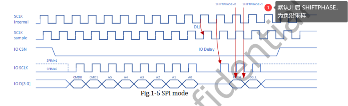
5.3 FSPI setup/hold timing is not measured: Chinese original figure, page 31
2. DLL (delay line) requirement. Combined I/O delay from FSPI timing constraints and the output delay of most devices leaves marginal setup/hold time, so a delay line is added to find the best sampling margin.
3. DLL characteristics. RK FSPI supports a read-sampling delay line. Its delay is added inside the chip and cannot be measured at the I/O. DLL is affected by PVT and fabrication process; the delay is neither constant nor a phase-locked delay. It is superimposed on the falling-edge sampling described above. Thus the exact DLL delay cannot be calculated and is not visible in the external signal.
4. DLL software policy. Enable DLL when the I/O rate exceeds 50MHz. Each software stage tunes it by comparing flash IDs.
Summary: RK-host FSPI read setup/hold is not measured because most FSPI I/O clocks exceed 50MHz and use DLL, whose actual internal sampling timing is not externally measurable as explained above. Below 50MHz, the basic FSPI sampling scheme has substantial margin.
5.4 Can two FSPI chip selects connect different devices?
If the chip provides an FSPI CS1N I/O extension, the IP theoretically supports two chip selects. Only the CS0N device is bootdev. The two devices share many I/Os, so interference can affect operating rates. Perform a complete hardware/software assessment.
6. NAND issues
6.1 Changing PX30 NAND to rkflash
See the Storage chapter of Rockchip_Developer_Guide_UBoot_Nextdev_CN for rk_nand/rk_flash. rk_nand mainly serves high-capacity MLC/TLC NAND; rk_flash serves SLC NAND. PX30 SDKs generally provide high-capacity NAND firmware, so switching to SLC NAND requires driver changes. Main changes:
1. In rkbin, use Loader firmware packaged with RKBOOT/PX30MINIALL_SLC.ini.
2. In U-Boot, follow the Storage chapter of Rockchip_Developer_Guide_UBoot_Nextdev_CN and replace the RKNAND driver with RKFLASH.
3. Similarly in the kernel, change RK_NAND to RK_FLASH and enable nandc0 in DTS.
Possible problem — Q1: U-Boot cannot boot normally. A1: the storage driver or DTS may not be configured correctly. Use the following commands to check:
=> dm tree
...
# 正常设备应有以下类似打印
rksfc [ + ] rksfc |-- sfc@ff4c0000 **
blk [ + ] rkflash_blk | |-- sfc@ff4c0000.spinand.blk
blk [ ] rkflash_blk | `-- sfc@ff4c0000.spinor.blk
6.2 Rules for custom NAND reads/writes in U-Boot
For infrequent erase/write operations, calling MTD directly may be acceptable. Some customers, however, frequently log data in U-Boot to a raw partition without a filesystem and do not want to use the vendor partition. To reduce NAND wear from in-place erasing/writing, add a dedicated partition and implement reads/writes like the vendor partition. Reference: arch/arm/mach-rockchip/vendor.c, interfaces mtd_vendor_storage_init and mtd_vendor_write.
Vendor-partition implementation:
Initialization detects vnvm and registers the vendor interface if present. Two copies are written each time; writes are page-aligned and start at the first page of a block, while erasing covers the whole block.
6.3 NAND SFTL space allocation
| Device capacity | idblock | User data | Reserved data | sys block | Overhead |
|---|---|---|---|---|---|
| 128MB | 2MB | 107MB | 11MB | 8MB | 14.8% |
| 256MB | 2MB | 218MB | 24MB | 12MB | 14% |
| 512MB | 2MB | 464MB | 31MB | I5MB | 9% |
The 11M region is used for flash data exchange to improve read/write efficiency; sys block is dedicated to FTL.
6.4 Do not combine separate NAND images into one programming operation
A programmer must ultimately program partitions separately because runtime bad-block management is partition-local, and preprogramming must match it. Some programmers support custom or open-source all_in_one packaging: separate images are packed together, possibly with partition metadata, then the programmer parses the special metadata, unpacks and programs partitions individually. Obtain a demo from the programmer manufacturer or develop one. RK has analyzed one all-in-one format; see the SPI NAND programmer document 20210804_flash_programer.
6.5 Bad-block-table management in open-source NAND
Bad-block-table requirements: almost all NAND operations must know whether a flash block is bad. Without caching, every query rereads the bad-block marker from a flash page, costing I/O time. New bad-block markers are also not always reliably written when a block becomes unstable.
MTD caches the first I/O-derived result in a bad block table; repeated queries use that cache. Rebooting rebuilds it, so the table should also be saved in nonvolatile storage. Cache reference: drivers/mtd/nand/bbt.c.
SLC NAND BBT in flash: the open-source SLC NAND framework already integrates persistent bad-block-table management, centralizing and updating bad-block information.
SPI NAND BBT in flash: the open-source framework described in the source does not provide persistent SPI NAND bad-block management. RK therefore supplies its own support, enabled by default. Code — U-Boot:
drivers/mtd/nand/bbt.c
Kernel:
drivers/rkflash/sfc_nand_mtd_bbt.c
Characteristics:
1. Integrates the existing bbt.cache mechanism in drivers/mtd/nand/bbt.c.
2. Reserve the last four NAND blocks as candidate bad-block-table storage; adjust the final partition accordingly.
3. Generate the table in U-Boot on first power-on.
4. Write back two copies each time.
5. The source says U-Boot bad-block management does not involve deadlock because it has no real mutex/multithreading in this context.
7. Parallel SLC NAND issues
7.1 Creating PX30 SLC NAND IDB images
Different images require different creation methods:
1. IDB: export an image with OOB through the programmer, starting at flash block 0; length is normally two flash blocks.
2. Other images: use programmer_image_tool with -l to change the linked-list arrangement.
PX30 IDB programmer images are created separately because older platforms add one flash-info page and special ECC to the SLC NAND IDB region. programmer_image_tool does not implement this; newer platforms have no such flash-info page. The formats are therefore incompatible.
7.2 Manufacturer analysis reports many consecutive bad SLC NAND blocks
After removing an SLC NAND device and checking it with a programmer or another tool, customers or manufacturers may conclude that RK use created many bad-block marks. The source says this conclusion is incorrect: RK FTL uses a bad-block table, and spare byte 0 in used blocks cannot be interpreted as an ordinary bad-block marker. Third-party inspection of a removed device is therefore not conclusive; analyze real failures case by case.
7.3 SLC NAND programmer does not support master-device images
Assume the “image” contains data only:
1. SPI NAND relies on device-side ECC, so the programmed image contains only data and ECC is provided by the device.
2. SLC NAND relies on host-generated BCH for ECC protection. After RK BCH processes a page, data and OOB (metadata plus BCH code) are stored as shown:

7.3 SLC NAND programmer does not support master-device images: Chinese original figure, page 35
Re-layout: the normal data + OOB arrangement becomes interleaved data + OOB + data + OOB … . The original first-OOB-byte bad-block-marker location now falls inside data. After programming, SLC NAND cannot be judged by the manufacturer default first-OOB-byte marker rule. RK software identifies a bad block by first confirming BCH failure and then checking the first OOB byte for the bad-block marker. Consequently, a programmer cannot correctly skip bad blocks when reading the programmed image back.
7.4 SLC NAND programmer images contain data plus OOB
OOB (metadata and BCH) is added at image creation. Configure the programmer image as data with OOB.
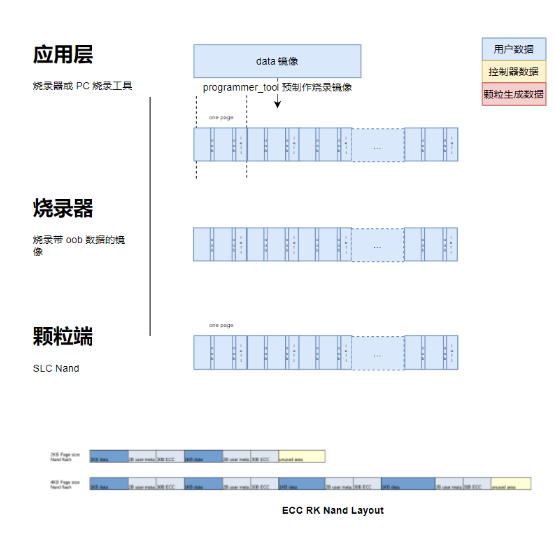
7.4 SLC NAND programmer images contain data plus OOB: Chinese original figure, page 36
7.5 SLC NAND SDK images contain data without OOB
OOB (metadata and BCH) is added by the controller; the user-programmed image contains data only.
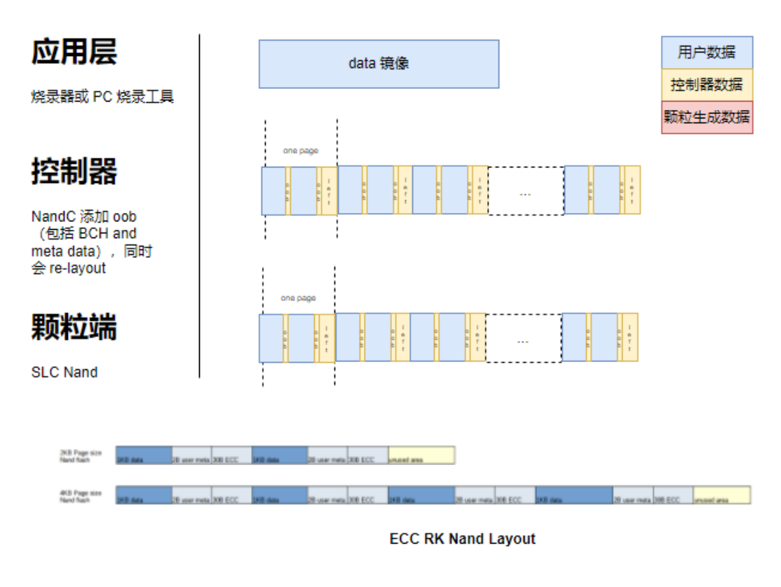
7.5 SLC NAND SDK images contain data without OOB: Chinese original figure, page 37
7.6 SLC NAND software ECC layout
RK SDK parallel SLC NAND uses the host-controller BCH module for ECC, configured as 16bits/1KB. Layout:

7.6 SLC NAND software ECC layout: Chinese original figure, page 37
7.7 Optimizing kernel rkflash SLC NAND throughput
CPU-scheduling trade-off:
1. Update the storage patch using the source storage-patch link.
2. In drivers/rkflash/nandc.c, change usleep_range from 20–30 to 5–10. The source describes adjusting sleep granularity to optimize CPU-thread scheduling at the cost of some transfer speed. Conversely, increasing sleep duration reduces CPU load under high I/O throughput. These are source statements; tune only after measuring the actual workload.
7.8 Optimizing SPL MTD SLC NAND read rates
Background: PP NAND device specifications vary, so NandC is configured conservatively for stability. Products requiring higher speed may apply appropriate optimizations.
Patch update/check: for RV1126, add the following U-Boot patch, rebuild and update SPL for 30MHz I/O:
diff --git a/arch/arm/mach-rockchip/rv1126/rv1126.c b/arch/arm/mach-rockchip/rv1126/rv1126.c
index 84df82ab138..e3ae330e413 100644
--- a/arch/arm/mach-rockchip/rv1126/rv1126.c
+++ b/arch/arm/mach-rockchip/rv1126/rv1126.c
@@ -77,6 +77,7 @@ DECLARE_GLOBAL_DATA_PTR;
 #define CRU_CLKSEL_CON50       0x1c8
 #define CRU_CLKSEL_CON51       0x1cc
 #define CRU_CLKSEL_CON54       0x1d8
+#define CRU_CLKSEL_CON59       0x1ec
 #define CRU_CLKSEL_CON61       0x1f4
 #define CRU_CLKSEL_CON63       0x1fc
 #define CRU_CLKSEL_CON65       0x204
@@ -749,6 +750,11 @@ int arch_cpu_init(void)
        udelay(1);
        writel(0x00100000, CRU_BASE + CRU_SOFTRST_CON10);

+#ifdef CONFIG_SPL_BUILD
+       writel(0x00ff004, CRU_BASE + CRU_CLKSEL_CON59);
+       printf("NandC gpll=768,div=(%d+1)\n", readl(CRU_BASE + CRU_CLKSEL_CON59) & 0xff);
+#endif
+
        return 0;
 }
 #endif
diff --git a/drivers/mtd/nand/raw/rockchip_nand_spl.c b/drivers/mtd/nand/raw/rockchip_nand_spl.c
index 6e39287ef39..d6ed7038914 100644
--- a/drivers/mtd/nand/raw/rockchip_nand_spl.c
+++ b/drivers/mtd/nand/raw/rockchip_nand_spl.c
@@ -92,7 +92,7 @@ static u32 nand_block_num;

 static void nandc_init(struct rk_nand *rknand)
 {
-       writel(0x1081, rknand->regs + NANDC_REG_V6_FMWAIT);
+       writel(0x1061, rknand->regs + NANDC_REG_V6_FMWAIT);
 }

 static void rockchip_nand_wait_dev_ready(void __iomem *regs)
After increasing SPL NandC speed, check:
1. Signal quality against the device specification.
2. Stress stability; repeated reboot tests can be used.
7.9 Too many bad blocks at SLC NAND tail break MTD operation
For kernel 4.19, first verify that this patch is applied:
commit e323080273b1e6ad2862158c2c634bf9f36671b2
Author: Jon Lin <jon.lin@rock-chips.com>
Date:   Tue Aug 29 15:56:56 2023 +0800

    mtd: rawnand: rockchip: Modify the judgment of the last page

    Incorrect judgment without affecting bad block judgment logic.

    Change-Id: I123be12cc50e52e6a24c4276a5ac68208239af42
    Signed-off-by: Jon Lin <jon.lin@rock-chips.com>
8. SPI NAND frequently asked questions
8.1 SPI NAND plane-select compatibility
Problem: RV1126/RV1109 have compatibility issues with some two-plane SPI NAND devices. IDB must be reduced to bring them up, so these devices are not recommended; the support list indicates this.
Compatibility workaround: RK provides a reduced SPL configuration, configs/rv1126-spl-spi-nand_defconfig. Main removals:
1. Other storage support: parallel NAND, EMMC, SPI NOR and SD card.
2. GPT support.
3. A/B partitions. If these features are needed, prune other unused manufacturer-device definitions below to make room for them:
CONFIG_MTD_SPI_NAND=y
CONFIG_SPI_NAND_GIGADEVICE=y
CONFIG_SPI_NAND_MACRONIX=y
CONFIG_SPI_NAND_MICRON=y
CONFIG_SPI_NAND_TOSHIBA=y
CONFIG_SPI_NAND_WINBOND=y
CONFIG_SPI_NAND_DOSILICON=y
CONFIG_SPI_NAND_ESMT=y
CONFIG_SPI_NAND_XTX=y
CONFIG_SPI_NAND_HYF=y
CONFIG_SPI_NAND_FMSH=y
CONFIG_SPI_NAND_FORESEE=y
CONFIG_SPI_NAND_BIWIN=y
Check whether the IDB combining spl.bin and ddr.bin fits. Run the following in U-Boot’s directory, replacing ddr.bin with the target firmware:
./tools/mkimage -n rv1126 -T rksd -d ./../rkbin/bin/rv11/rv1126_ddr_924MHz_v1.05.bin:./spl/u-boot-spl.bin rv1126_idb1.bin
Devices known in the source to have this issue:
| Device marking | ID0 | ID1 |
|---|---|---|
| MT29F2G01ABA, XT26G02E, F50L2G41XA | 2C | 24 |
| DS35Q2GA-IB | E5 | 72 |
| DS35M2GA-IB | E5 | 22 |
| FM25S02A | A1 | E5 |
| DS35Q2GB-IB | E5 | F2 |
| DS35Q4GM | E5 | F4 |
BOOTROM cannot scan data in odd-numbered blocks 1, 3, 5, … of these devices. A block is 128KB; if IDB exceeds 128KB, it crosses a block boundary and BOOTROM cannot find all IDB data, so loading fails.
8.2 Selecting 1.8V SPI NAND
1.8V devices are generally available from manufacturers. The source reports support for seven manufacturers; consult the latest flash support list rather than treat this as a current count. With domain configuration and I/O supply switched correctly, the storage driver is compatible with 3.3V operation without special configuration:
| Source record | Manufacturer | Model | Capacity (bits) | Capacity (bytes) | Voltage | Interface |
|---|---|---|---|---|---|---|
| 20230705 | XTX | XT26Q04DWSIGA | 4GBits | 512MB | 1.7V- 1.95V |
SPI NAND |
| 20230705 | XTX | XT26Q01DWSIGA | 1GBits | 128MB | 1.7V- 1.95V |
SPI NAND |
| 20230705 | XTX | XT26Q02DWSIGA | 2GBits | 256MB | 1.7V- 1.95V |
SPI NAND |
| 20230705 | FORESEE | F35UQA002G- WWT |
2GBits | 256MB | 1.7V- 1.95V |
SPI NAND |
| 20230705 | FORESEE | F35UQA001G- WWT |
1GBits | 128MB | 1.7V- 1.95V |
SPI NAND |
| 20230317 | HYF | HYF1GQ4IDACAE | 1GBits | 128MB | 1.70V- 1.98V |
SPI NAND |
| 20230317 | HYF | HYF2GQ4IAACAE | 2GBits | 256MB | 1.70V- 1.98V |
SPI NAND |
| 20230217 | Dosilicon | DS35M12B-IB | 512MBits | 64MB | 1.7V- 1.95V |
SPI NAND |
| 20220901 | MXIC | MX35UF1GE4AD- Z4I |
1GBits | 128MB | 1.7V- 1.95V |
SPI NAND |
| 20220818 | MXIC | MX35UF4GE4AD- Z4I |
4GBits | 512MB | 1.7V- 1.95V |
SPI NAND |
| 20220818 | MXIC | MX35UF2GE4AD- Z4I |
2GBits | 256MB | 1.7V- 1.95V |
SPI NAND |
| 20210918 | GigaDevice | GD5F2GM7REYIGY | 2GBits | 256MB | 1.7V- 2.0V |
SPI NAND |
| 20210911 | Dosilicon | DS35M2GA-IBR | 2GBits | 256MB | 1.7V- 2.0V |
SPI NAND |
| 20210911 | Dosilicon | DS35M1GA-IBR | 1GBits | 128MB | 1.7V- 1.95V |
SPI NAND |
| 20210911 | Dosilicon | DS35M1GB-IB | 1GBits | 128MB | 1.7V- 1.95V |
SPI NAND |
| 20210911 | GigaDevice | GD5F2GQ5REYIG | 2GBits | 256MB | 1.7V- 2.0V |
SPI NAND |
| 20210911 | GigaDevice | GD5F1GQ5REYIG | 1GBits | 128MB | 1.7V- 2.0V |
SPI NAND |
| 200701 | Dosilicon | DS35M1GA-IBR | 1GBits | 128MB | 1.65V- 1.95V |
SPI NAND |
| 200831 | MXIC | MX35UF1GE4AC- Z4I |
1GBits | 128MB | 1.7V- 1.95V |
SPI NAND |
| 200831 | MXIC | MX35UF2GE4AC- Z4I |
2GBits | 256MB | 1.7V- 1.95V |
SPI NAND |
8.3 HYF1GQ4UTXCAE power-loss issue
The manufacturer-supplied HYF1GQ4UTXCAE failed power-loss testing. The source attributes this to missing upstream HWP_EN adjustments for this device family:
commit 72986913fc4ba3e0c1c276aa63e2040ff8290201
Author: Jon Lin <jon.lin@rock-chips.com>
Date:   Mon Aug 14 14:52:36 2023 +0800

    mtd: spinand: Enable HWP_EN for skyhigh devices

    HWP_EN must be enabled first before block unlock region is set.

    Change-Id: I6b107d97de48bb2644da865f353d2adace95224e
    Signed-off-by: Jon Lin <jon.lin@rock-chips.com>
8.4 Exploring software ECC for SPI NAND
The source distinguishes correction from validity detection: software ECC provides little extra correction here but may help determine data validity; the RK scheme itself uses device-integrated hardware ECC.
SPI NAND needs ECC because NAND can experience bit flips. Hardware ECC is usually integrated in the device, or sometimes in the host (the source gives HiSilicon as an example). RK does not support SPI NAND without integrated hardware ECC by default because reliability would be too low.
If hardware ECC already exists, software ECC adds little correction: a hardware-ECC failure normally represents widespread corruption beyond small software-correction capability. It may still detect invalid data from exceptional transfer-path problems such as unexpected power loss, which hardware ECC may not report. A UBIFS-like data-check mechanism is therefore useful.
For partitions without filesystems, such as misc, consider ECC or another effective data-protection mechanism to protect SPI NAND reads/writes under extreme conditions.
8.5 Protection for SPI NAND BBT stored in flash
Background: RK SPI NAND SDK stores flash bad-block information in BBT; see the bad-block-table requirements section of this FAQ. Earlier validation mainly used the first OOB byte and magic at the end of valid BBT data.
Patch versions — U-Boot:
commit 78cac1dffdc0bd64e47294e41d2432b7760e7186
Author: Jon Lin <jon.lin@rock-chips.com>
Date:   Sun Jun 28 20:13:39 2020 +0800

    mtd: nand: Remove bbt option property if scan fail

    Change-Id: Ifb5b500b6ffee551aea5b6aecea629b3d0ea6207
    Signed-off-by: Jon Lin <jon.lin@rock-chips.com>
Kernel:
commit fe246b156492ee509bb1d071c176d324542d3193
Author: Jon Lin <jon.lin@rock-chips.com>
Date:   Thu Dec 17 16:05:27 2020 +0800

    drivers: rkflash: Fixed bbt operation calculation error

    Fixes: 008340a82 ("drivers: rkflash: Change to use the api which the oob area available")
    Change-Id: I140aa76a2acb73271ba04b7060030dc06a2353e6
    Signed-off-by: Jon Lin <jon.lin@rock-chips.com>
Optimization: unstable SPI NAND can destructively affect BBT even when BBT logic is not the root cause. Add protection for these boundary cases. BBT framework:
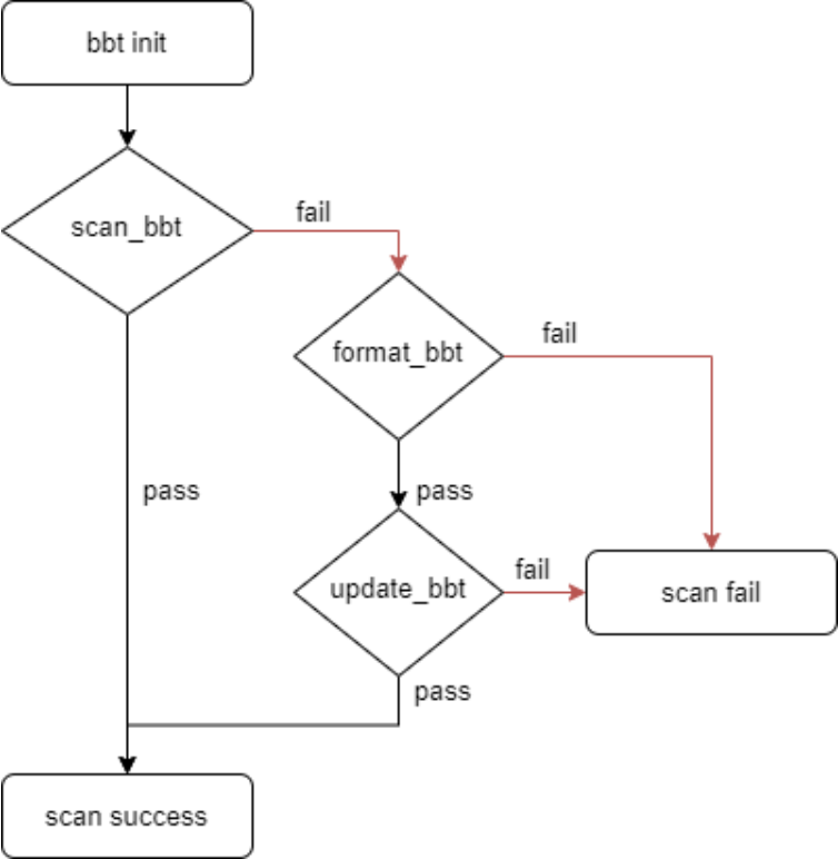
8.5 Protection for SPI NAND BBT stored in flash: Chinese original figure, page 43
Additional protection:
- Add a hash to validate BBT information.
- During format_bbt full-flash scanning, recheck suspicious blocks identified as bad.
- During update_bbt, read back and verify written BBT data; erase redundant information if verification fails.
Fault-injection tests in U-Boot/kernel simulate startup BBT-scan failures, errors while scanning all blocks during BBT formatting, and BBT-write, hash, read-back and read-back-hash failures. SPL cannot format BBT and has no destructive operation, so the source does not inject faults there. After stress testing, BBT remained normal with no erroneous bad-block information according to the source.
Optimization patches — U-Boot:
commit 55ef8700b677919efa06f3bfe1dcab3a4554a92d
Author: Jon Lin <jon.lin@rock-chips.com>
Date:   Sun Sep 24 20:11:20 2023 +0800

    mtd: nand: bbt: Add mechanisms to protect bad block tables

    1.Add hash check
    2.Add anti-shake mechanism to avoid damaging the bad block tables
    3.Add anti-shake mechanism to optimize the reliability of bad block table

    Change-Id: I6ac9554ae0f642d6a89d21a8f79a2a87d607f993
    Signed-off-by: Jon Lin <jon.lin@rock-chips.com>
Kernel:
commit cc1f433fb9ade372b06e9d62651ed8d719aaac94
Author: Jon Lin <jon.lin@rock-chips.com>
Date:   Sun Sep 24 20:24:00 2023 +0800

    drivers: rkflash: Add mechanisms to protect bad block tables

    1.Add hash check
    2.Add anti-shake mechanism to avoid damaging the bad block tables
    3.Add anti-shake mechanism to optimize the reliability of bad block table

    Change-Id: I888ceba54e5bbc55283850316e27560c484a9cf5
    Signed-off-by: Jon Lin <jon.lin@rock-chips.com>
8.6 SPI NAND programmer supports masters but not a full-image export
The source recommends creating programmer images with RK programmer_image_tool rather than from a master device. Its heading says a master is supported, but the body rejects exporting one complete SPI NAND master image because Linux MTD/UBIFS manage bad blocks by partition. Preserve this heading/body conflict for verification.
Example: partition A is 8MB and contains one 128KB bad block; partition B is also 8MB. Program a 7MB A image and a 7MB B image. If a combined image is 7MB_A + 1MB padding + 7MB_B, skipping a bad block during programming places valid A data at address 0 and B data at 8MB + 128KB. Software still defines B at 8MB and starts loading there, so the image is misaligned.
Correct method: program A separately at address 0 and B separately at 8MB, writing with skip-bad-block behavior from each partition start. Software reads each partition image with the same skip-bad-block strategy from its partition start. Programming and reading then agree.
8.7 SPI NAND SDK images contain data without OOB
Reason: the SPI-flash controller has no integrated ECC and therefore depends on device-side ECC.
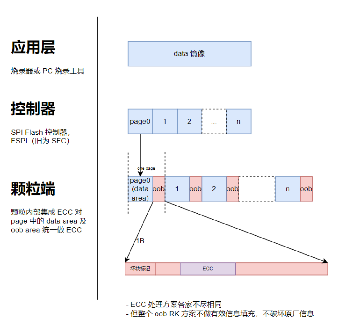
8.7 SPI NAND SDK images contain data without OOB: Chinese original figure, page 45
8.8 Optimizing kernel rkflash SPI NAND throughput
Large I/O transfers can indeed produce high CPU load. Sacrificing some flash speed can improve CPU scheduling.
diff --git a/drivers/rkflash/sfc_nand.c b/drivers/rkflash/sfc_nand.c
index 0bc1c6b43fd7..ca190c115ad3 100644
--- a/drivers/rkflash/sfc_nand.c
+++ b/drivers/rkflash/sfc_nand.c
@@ -274,7 +274,7 @@ static int sfc_nand_wait_busy(u8 *data, int timeout)

        *data = 0;

-       for (i = 0; i < timeout; i++) {
+       for (i = 0; i < timeout; i+= 20) {
                ret = sfc_nand_read_feature(0xC0, &status);

                if (ret != SFC_OK)
@@ -285,7 +285,7 @@ static int sfc_nand_wait_busy(u8 *data, int timeout)
                if (!(status & (1 << 0)))
                        return SFC_OK;

-               sfc_delay(1);
+               usleep_range(20, 30);
        }

        return SFC_NAND_WAIT_TIME_OUT;
8.9 Kernel MTD SPI NAND device and bad-block information
Bad-block information:
cat /sys/devices/virtual/mtd/mtd5/bad_blocks
Other information:
# ls /sys/devices/virtual/mtd/mtd4/
bad_blocks         ecc_step_size      numeraseregions    subsystem/
bbt_blocks         ecc_strength       offset             type
bitflip_threshold  erasesize          oobsize            uevent
corrected_bits     flags              power/             writesize
dev                mtdblock4/         size
ecc_failures       name               subpagesize
8.10 Kernel MTD SPI NAND write failure
Check whether the device is one of these source-listed models:
- S35ML01G3, ANV1GCP0CLG, HYF1GQ4UTXCAE, YX25G1E.
- S35ML02G3, ANV2GCP0CLG, HYF2GQ4UTXCAE, YX25G2E.
The two source lines were joined during extraction; model names are unchanged.
These devices have compatibility issues with command 84h. A patch was added, and the manufacturer was asked to correct its documentation.
commit 328145662f6d6154fbf4329a0d53f9c152673648
Author: Jon Lin <jon.lin@rock-chips.com>
Date:   Fri Jul 7 12:06:40 2023 +0800

    mtd: spinand: skyhigh: The vendor requires the devices to be patched

    1.Double OIP=0 after page 13H
    2.The nand flash does not support 84H and 34H command

    Change-Id: Ie805f42a36e1a864115988087bdc43592cc94ded
    Signed-off-by: Jon Lin <jon.lin@rock-chips.com>
8.11 Automatic root mount for both MTD SPI NAND and EMMC
The default SDK does not support this. To support both EMMC and SPI NAND, detect the storage type in U-Boot and pass the corresponding root parameter through kernel bootargs.
8.12 ENV-partition upgrades with 4K-page SPI NAND IDB images
For devices with 4KB pages, generate the idblock upgrade image with this special command:
./tools/programmer_image_tool -i rv1106_download_v1.14.108.bin -b 128 -p 4 -2 -t spinand -o ./
Output: idblock.img. The latest SDK described by the source generates this image by default.
8.13 SPI NAND fast boot does not build kernel BBT
SPI NAND page-read speed issue/optimization: a fast-boot SPL path bypasses U-Boot, and the kernel bad-block-table creation is incompatible or absent. See the patch:
commit c7270465b2a699211dfd8ad3c2f882f22247c40c
Author: Jon Lin <jon.lin@rock-chips.com>
Date:   Thu Dec 17 16:05:27 2020 +0800

    drivers: rkflash: Fixed bbt operation calculation error

    Fixes: 008340a82 ("drivers: rkflash: Change to use the api which the oob area available")
    Change-Id: I140aa76a2acb73271ba04b7060030dc06a2353e6
    Signed-off-by: Jon Lin <jon.lin@rock-chips.com>
8.14 Custom MTD upgrade fails for a partition containing bad blocks
Cause: random-offset writes inside a partition. For example, write a roughly 2M image using nandwrite in 512K pieces, increasing the next offset by 512K. Encountering a bad block can make U-Boot MTD reads fail. Write the image in one operation, or implement your own bad-block management.
Why: writes not performed as one operation aligned to the partition start may fail to account for skipped blocks. If block 8 is bad, write 7_8 actually writes 7_9. A later write 9 again writes block 9, causing repeated programming and ECC failure when its data is read back.
8.15 Continuous-read SPI NAND support and fast-boot adaptation
8.15.1 Introduction
Winbond (spelled “Winbound” once in the source) provides special SPI NAND fast loading on selected devices. W25N01GV supports bad-block replacement to make a configured area bad-block-free, continuous read across page boundaries while clocks continue, and 104MHz SDR continuous-read clocking with a stated SDR throughput of 52MB/s.
The Winbond W25N01XX CONT_READ fast-boot scheme uses this device feature to accelerate ROM loading, accelerate SPL loading, and asynchronously load selected SPL firmware in the background using FSPI DMA. These are source capabilities and rates, not ArmSoM test results.
8.15.2 Configuration
RV1103B rkbin INI example: RV1103BMINIALL_SPI_NAND_W25N01XX_TB.ini.
U-Boot configuration:
CONFIG_SPI_NAND_WINBOND_CONT_READ
9. SPI NOR issues
9.1 Selecting 1.8V SPI NOR of 256Mbits or more
Source-listed devices:
- MX25U25645GZ4I-00: 256MBits, 32MB.
- MX25U51245GZ4I00: 512Mbits, 64MB.
- GD25LQ256CW1G: 256MBits, 32MB.
- W25Q256JWEQ: 256MBits, 32MB.
- XTX XT25W512BSFHGU: 512Mbit, 1.65–3.6V, not validated in the source.
- Dosilicon DS25M4BA-1AIB1: 256Mb, not validated.
- Dosilicon DS25M4BA-1AIB4: 256Mb, not validated.
Consult these manufacturers for parts meeting product requirements. For parts RK has not validated, submit samples for validation. Use the latest flash support list to determine supported devices; the list above is not an ArmSoM qualification.
9.2 rkflash SPI NOR versus open-source MTD in kernel 4.4 and earlier
Older kernel open-source frameworks support relatively few devices and use an older MTD architecture, so RK did not adapt them. The rkflash solution implements support for more SPI-flash devices.
9.3 SPI NOR MTD sf commands and U-Boot interfaces
RK SDK U-Boot uses DM_SPI_FLASH. Interfaces in spi_flash.h include spi_find_bus_and_cs and spi_flash_probe_bus_cs for initialization, plus spi_flash_read and related read/write functions. For usage, see cmd/sf.c and the U-Boot command cmd_sf.
RV1106 example patch:
diff --git a/arch/arm/dts/rv1106-u-boot.dtsi b/arch/arm/dts/rv1106-u-boot.dtsi
index b0632e9ce9..03bc933125 100644
--- a/arch/arm/dts/rv1106-u-boot.dtsi
+++ b/arch/arm/dts/rv1106-u-boot.dtsi
@@ -167,6 +167,7 @@
                spi-tx-bus-width = <1>;
                spi-rx-bus-width = <4>;
                spi-max-frequency = <80000000>;
+               status = "disabled";
        };

        spi_nor: flash@1 {
diff --git a/configs/rv1106_defconfig b/configs/rv1106_defconfig
index 9b20bcfb65..b1f3933a11 100644
--- a/configs/rv1106_defconfig
+++ b/configs/rv1106_defconfig
@@ -148,3 +148,4 @@ CONFIG_SPL_LZMA=y
 CONFIG_SPL_GZIP=y
 CONFIG_ERRNO_STR=y
 # CONFIG_EFI_LOADER is not set
+CONFIG_CMD_SF=y
Commands:
=> sf probe 2:0 10000000 3
SF: Detected sfc_nor with page size 256 Bytes, erase size 4 KiB, total 16 MiB

=> sf read 0x400000 0x200 0x200
device 0 offset 0x200, size 0x200
SF: 512 bytes @ 0x200 Read: OK
9.4 SPI NOR MTD mtdparts registration is slow
Every MTD partition is an MTD device. Enabling mtdblock additionally registers block devices, increasing total registration time. Source example for add_mtd_device:
- device_register: 0.15ms.
- mtd_nvmem_add: 0.08ms.
- device_create: 0.12ms.
- mtdpstore_notify_add: 0.5ms.
9.5 SPI NOR MTD erase/write is slow in U-Boot
If JFFS2 is not used in U-Boot, remove SPI_FLASH_USE_4K_SECTORS and use 64KB-aligned erases.
9.6 Single-line versus four-line SPI NOR performance
Test environment: 80MHz I/O clock.
| I/O use | io0~3 bidirectional | io0~1 bidirectional | io0 receive, io1 transmit |
| Filesystem read | 35MB/s | 19MB/s | 11MB/s |
| Filesystem erase/write | 150KB/s | 150KB/s | 150KB/s |
“Single-line” SPI flash does not literally mean only one physical I/O is involved; it describes one unidirectional transfer.
9.7 SPI NOR stress failures at higher rates
Example device rated at 104MHz: some characteristics are limited to 83MHz, and tests were unstable at 80MHz.
Goal: pass stress tests at 80MHz I/O. First measure key kernel-stage signals clk, d0, d1 and cs, preferably simultaneously, and check for clear signal-quality problems. If none appear:
- Test A: reduce the suspect device to 60MHz and run high/low-temperature automatic reboot stress tests.
- Test B: choose another manufacturer’s similarly rated 100MHz device and run automatic reboot tests as a control for board quality.
Interpretation:
- Both A and B fail: the board hardware is likely limiting SPI NOR speed; investigate signals further.
- Both pass, while default 80MHz fails: the source suspects an overstated rating for the original device.
- A fails and B passes: reduce A to 40MHz and continue. If 40MHz passes, the source suspects a severely overstated rating or poor compatibility.
Continue according to the results. If the device performs acceptably and is selected, assess whether 60MHz meets product requirements. These are diagnostic hypotheses from the source, not verified manufacturer-quality judgments.
9.8 SPI NOR AUTO_MERGE
9.8.1 Introduction
The source describes market situations where two 16MB SPI NOR devices cost substantially less than one 32MB device. AUTO_MERGE combines two SPI NOR devices into one larger logical device to simplify deployment, development and maintenance:
- Device tree defines one NOR device.
- The framework scans one AUTO_MERGE NOR device with two subdevices.
- Userspace sees one NOR device.
The price comparison is historical source context, not a current quotation.
9.8.2 Restrictions
Restrictions:
- AUTO_MERGE combines only two identical SPI NOR devices and requires similar PCB routing/layout.
- A single SPI NOR is supported, but the CS1N GPIO pin still outputs signals during detection.
- SPL FSPI-DMA asynchronous background-loading regions must not cross the physical NOR-device boundary; for example, fast-boot ramdisk uses preload in DTS.
- Open-source usbplug may be rebuilt, but supports only USB download. For UART download, use the closed-source download_xxxcs1.bin and usbplug_xxxcs1.bin, packaged by the integrator.
9.8.3 Configuration
RV1103B rkbin INI example: RKBOOT/RV1103BMINIALL_AUTO_MERGE.ini.
usbplug/SPL/U-Boot build options:
CONFIG_SPI_FLASH_AUTO_MERGE=y
CONFIG_SPL_GPIO_SUPPORT=y
usbplug/SPL/U-Boot DTS options:
diff --git a/arch/arm/dts/rv1103b-u-boot.dtsi b/arch/arm/dts/rv1103b-u-boot.dtsi
index a31355a..88ceb85 100644
--- a/arch/arm/dts/rv1103b-u-boot.dtsi
+++ b/arch/arm/dts/rv1103b-u-boot.dtsi
@@ -67,12 +67,12 @@
 };

 &gpio1 {
-   u-boot,dm-pre-reloc;
+   u-boot,dm-spl;
    status = "okay";
 };

 &gpio2 {
-   u-boot,dm-pre-reloc;
+   u-boot,dm-spl;
    status = "okay";
 };

@@ -92,6 +92,7 @@
 };

 &sfc {
+   sfc-cs-gpios= <&gpio1 RK_PA5 GPIO_ACTIVE_LOW>, <&gpio2 RK_PA6 GPIO_ACTIVE_LOW>;
    u-boot,dm-spl;
    status = "okay";
    };
Kernel build option:
CONFIG_MTD_SPI_NOR_AUTO_MERGE=y
Kernel DTS reference:
&fspi0 {
    sfc-cs-gpios = <&gpio1 RK_PA5 GPIO_ACTIVE_LOW>, <&gpio1 RK_PA6 GPIO_ACTIVE_LOW>;
    pinctrl-names = "default";
    pinctrl-0 = <&fspi_cs0n &fspi_cs1n>;
    status = "okay";

    flash@0 {
        compatible = "jedec,spi-nor";
        reg = <0>;
        spi-max-frequency = <75000000>;
        spi-rx-bus-width = <4>;
        spi-tx-bus-width = <1>;
    };
};

&pinctrl {
    fspi {
        fspi_cs0n: fspi-cs0n {
            rockchip,pins = <1 RK_PA5 RK_FUNC_GPIO &pcfg_pull_up>;
        };
        fspi_cs1n: fspi-cs1n {
            rockchip,pins = <1 RK_PA6 RK_FUNC_GPIO &pcfg_pull_up>;
        };
    };
};
9.8.4 CSN1 configuration
Use the CSN1 GPIO pin recommended by RK. Obtain hardware drawings from the responsible hardware engineer. usbplug/SPL/U-Boot DTS example: change RV1103B GPIO1A6 to GPIO1A7:
diff --git a/arch/arm/dts/rv1103b-u-boot.dtsi b/arch/arm/dts/rv1103b-u-boot.dtsi
index d346eae20bf..86265f76304 100644
--- a/arch/arm/dts/rv1103b-u-boot.dtsi
+++ b/arch/arm/dts/rv1103b-u-boot.dtsi
@@ -92,7 +92,7 @@
 };

 &sfc {
-       sfc-cs-gpios= <&gpio1 RK_PA5 GPIO_ACTIVE_LOW>, <&gpio1 RK_PA6 GPIO_ACTIVE_LOW>;
+       sfc-cs-gpios= <&gpio1 RK_PA5 GPIO_ACTIVE_LOW>, <&gpio1 RK_PA7 GPIO_ACTIVE_LOW>;
        u-boot,dm-spl;
        status = "okay";

diff --git a/arch/arm/mach-rockchip/rv1103b/rv1103b.c b/arch/arm/mach-rockchip/rv1103b/rv1103b.c
index 7353528afdd..8e30240076e 100644
--- a/arch/arm/mach-rockchip/rv1103b/rv1103b.c
+++ b/arch/arm/mach-rockchip/rv1103b/rv1103b.c
@@ -252,9 +252,9 @@ int arch_cpu_init(void)
        writel(0x00000000, USBPHY_APB_BASE + USBPHY_FSLS_DIFF_RECEIVER);

 #ifdef CONFIG_SPI_FLASH_AUTO_MERGE
-       /* gpio1a5/gpio1a6 cs-gpio */
+       /* gpio1a5/gpio1a7 cs-gpio */
        writel(0x00F00000, GPIO1_IOC_BASE + GPIO1A_IOMUX_SEL_1_0);
-       writel(0x0F000000, GPIO1_IOC_BASE + GPIO1A_IOMUX_SEL_1_1);
+       writel(0xF0000000, GPIO1_IOC_BASE + GPIO1A_IOMUX_SEL_1_1);
 #endif
 #endif
Kernel example: change RV1103B GPIO1A6 to GPIO1A7:
diff --git a/arch/arm/boot/dts/rv1103b-evb1-v10-spi-nor-auto-merge.dts b/arch/arm/boot/dts/rv1103b-evb1-v10-spi-nor-auto-merge.dts
index ae3fa579b05f..00bf8008e107 100644
--- a/arch/arm/boot/dts/rv1103b-evb1-v10-spi-nor-auto-merge.dts
+++ b/arch/arm/boot/dts/rv1103b-evb1-v10-spi-nor-auto-merge.dts
@@ -14,7 +14,7 @@ / {
 };

 &fspi0 {
-       sfc-cs-gpios = <&gpio1 RK_PA5 GPIO_ACTIVE_LOW>, <&gpio1 RK_PA6 GPIO_ACTIVE_LOW>;
+       sfc-cs-gpios = <&gpio1 RK_PA5 GPIO_ACTIVE_LOW>, <&gpio1 RK_PA7 GPIO_ACTIVE_LOW>;
        pinctrl-names = "default";
        pinctrl-0 = <&fspi_cs0n &fspi_cs1n>;
        status = "okay";
@@ -34,7 +34,7 @@ fspi_cs0n: fspi-cs0n {
                        rockchip,pins = <1 RK_PA5 RK_FUNC_GPIO &pcfg_pull_up>;
                };
                fspi_cs1n: fspi-cs1n {
-                       rockchip,pins = <1 RK_PA6 RK_FUNC_GPIO &pcfg_pull_up>;
+                       rockchip,pins = <1 RK_PA7 RK_FUNC_GPIO &pcfg_pull_up>;
                };
        };
 };
10. Tool issues
10.1 Creating a standalone GPT image with upgrade_tool
Use Linux upgrade tool v1.67 or later.
./upgrade_tool gpt parameter.txt gpt.img
10.2 Unpacking Loader with boot_merger
./tools/boot_merger unpack -i rk356x_spl_loader_v1.01.102-528M-1115.bin -o .
10.3 LoaderToDDR in the Android upgrade tool
The tool Loader field has two configurations:
1. loader: starts the upgrade and extracts idb.img from the Loader image for programming.
2. loaderToDDR: starts the upgrade only.
10.4 Introduction to idb_bootconfig
ROM code normally loads SPI NOR firmware using one data line. Adding bootconfig to the packed IDB header can accelerate loading by selecting four-line transfers. The idb_bootconfig script inserts this NOR boot-acceleration configuration into IDB. Parameters vary by SPI NOR device. Therefore the source recommends adding them with idb_bootconfig rather than filling a prebuilt image with fixed data; otherwise each selected device requires its own bootconfig parameters.