
Platform reference for ArmSoM adaptation, not a claim that every board supports every feature. Sources: Rockchip_Developer_Guide_SDMMC_SDIO_eMMC_CN.pdf (22 pages) and its English counterpart (25 pages), both V1.4.0, RK-KF-YF-121. Chinese follows the Chinese source; English follows the English source; Russian and German fully translate English, with differences identified locally. Chinese uses Chinese-source figures; the other editions use English-PDF originals. The English PDF itself contains Chinese annotations in the oscilloscope figure; these have not been presented as translated graphics. Check the exact ArmSoM board, SoC, SDK/BSP, kernel, DTS, IO voltage, storage device and WiFi wiring. No hardware validation was performed; logs, frequencies and waveforms are source examples, not ArmSoM measurements.
Safety: source procedures include state changes, driver unbinding, write/erase tests, formatting and fsck repair. They can destroy data. Evaluate only on a backed-up, positively identified dedicated test card, never blindly on a system disk or production device. None of these operations was executed during editing.
| Chipset | Kernel version |
|---|---|
| Full series (source scope, not an all-ArmSoM support claim) | 4.4, 4.19, 5.10, 6.1 |
ArmSoM Docs · Rockchip Linux · EDITORIAL-NOTES
1. DTS Configuration
1.1 SDMMC DTS Configuration Guide
(1) max-frequency = <150000000>;
This configuration sets the operating frequency of the SD card. Although set to 150MHz, adjustments may be necessary depending on the different modes of the SD card. Users do not need to be concerned with this part, as the actual operating frequency and module relationship will be handled by the associated software. The maximum does not exceed 150MHz.
(2) supports-sd;
This configuration identifies the slot as an SD card function, which is a required addition. Without it, the SD card cannot be initialized. Note that after kernel 4.19, this configuration is no longer used, and instead, a combination of no-sdio and no-mmc is used to indicate that this card slot does not support SDIO and MMC, and is dedicated to SD functionality.
(3) bus-width = <4>;
This configuration identifies the bus width required for the SD card. The SD card supports up to a 4-line mode, and if not configured, it defaults to a 1-line mode. Additionally, only the values 1 and 4 are supported; configuring any other value will be considered illegal and will force the use of a 1-line mode.
(4) cap-mmc-highspeed; cap-sd-highspeed;
These configurations indicate that the slot supports highspeed SD cards. If not configured, it implies that highspeed SD cards are not supported.
(5) Configuring SD3.0 Usage
First, ensure that the chip supports SD3.0 mode and configure the IO power supply of the vqmmc route for the SDMMC controller, and add the following SD3.0 speed modes:
| Mode | Maximum frequency (source value) | Notes |
|---|---|---|
| sd-uhs-sdr12 | 24M | |
| sd-uhs-sdr25 | 50M | |
| sd-uhs-sdr50 | 100M | |
| sd-uhs-ddr50 | 50M | Dual-edge sampling |
| sd-uhs-sdr104 | 208M |
(6) Configuring the 3V3 Power Supply for SD Card Devices
If the hardware uses the power control pin of the chip’s SDMMC controller as the default power control pin for the SD card: sdmmc_pwren, then only need to configure the pinctrl as the functional pin for sdmmc_pwren and reference it in the default pinctrl of the sdmmc node, for example, using RK312X as an example:
sdmmc_pwren: sdmmc-pwren {
    rockchip,pins = <1 RK_PB6 1 &pcfg_pull_default>;
};
pinctrl-0 = <&sdmmc_pwr &sdmmc_clk &sdmmc_cmd &sdmmc_bus4>;
If the hardware uses another GPIO as the 3V3 power control pin for the SD card device, it needs to be defined as a regulator for use and referenced in the vmmc-supply within the sdmmc node, for example:
sdmmc_pwr: sdmmc-pwr {
    rockchip,pins = <7 11 RK_FUNC_GPIO &pcfg_pull_none>;
};
vcc_sd: sdmmc-regulator {
    compatible = "regulator-fixed";
    gpio = <&gpio7 11 GPIO_ACTIVE_LOW>;
    pinctrl-names = "default";
    pinctrl-0 = <&sdmmc_pwr>;
    regulator-name = "vcc_sd";
    regulator-min-microvolt = <3300000>;
    regulator-max-microvolt = <3300000>;
    startup-delay-us = <100000>;
    vin-supply = <&vcc_io>;
};
&sdmmc {
    vmmc-supply = <&vcc_sd>;
};
(7) Configuring SD Card Hot-Swap Detection Pins
If the detection pin is directly connected to the chip’s SDMMC controller’s sdmmc_cd pin, then simply configure the pin as a functional pin and reference it in the default pinctrl of the sdmmc node.
If the detection pin uses another GPIO, it needs to be configured using cd-gpios within the sdmmc node, for example:
cd-gpios = <&gpio4 24 GPIO_ACTIVE_LOW>;
If a GPIO detection pin is used, but an inverted detection method is required (i.e., the detection pin is high when the SD card is inserted), then add:
cd-inverted;
1.2 SDIO DTS Configuration Guide
(1) max-frequency = <150000000>;
This item is the same as the SD card configuration, with the maximum operating frequency not exceeding 150MHz; if an SDIO2.0 device is connected, it will automatically be compatible with a maximum of 50MHz, and if an SDIO3.0 device is connected, it will support up to 150MHz.
(2) supports-SDIO;
This configuration identifies this slot as an SDIO function, which is a required addition. Otherwise, the SDIO peripheral cannot be initialized. Note that after the 4.19 kernel, this configuration is no longer used, and the combination of no-sd and no-mmc is used to indicate that this card slot does not support SDMMC and MMC, and is dedicated to SDIO functionality.
(3) bus-width = <4>;
This configuration is the same as the SD card functionality.
(4) cap-sd-highspeed;
This configuration is the same as the SD card functionality, and as an SDIO peripheral, it also distinguishes whether it is a highspeed SDIO peripheral.
(5) cap-sdio-irq;
This configuration indicates whether the SDIO peripheral (usually WiFi) supports SDIO interrupts. If your peripheral is an OOB interrupt, please do not include this item. For the type of interrupt supported, please contact the WiFi manufacturer to confirm.
(6) keep-power-in-suspend;
This configuration indicates whether sleep power-off is supported, and this option should be added by default. WiFi generally has deep wake-up requirements.
Source discrepancy: CN p.6 explicitly says to keep power during suspend, whereas EN p.7 says “sleep power-off”. The original English wording is retained above; verify the property against the actual BSP.
(7) mmc-pwrseq = <&sdio_pwrseq>;
This item is the power control for the SDIO peripheral (usually WiFi) and is a required item, otherwise, WiFi cannot power up and work. Please refer to the example below, and the selection of crystal clock and reset- enable GPIO should be configured according to the actual board-level hardware requirements.
sdio_pwrseq:sdio-pwrseq {
        compatible ="mmc-pwrseq-simple";
        clocks = <&rk808 1>;
        clock-names ="ext_clock";
        pinctrl-names ="default";
        pinctrl-0 =<&wifi_enable_h>;
        /*
        * On the module itself this is one of these (depending
        * on the actual card populated):
        * - SDIO_RESET_L_WL_REG_ON
        * - PDN (power down when low)
        */
        reset-gpios = <&gpio0 10GPIO_ACTIVE_LOW>; /* GPIO0_B2 */
};
(8) non-removable;
This item indicates that the slot is a non-removable device and is a required addition for SDIO devices.
(9) num-slots = <4>;
This item is the same as the SD card configuration.
(10) sd-uhs-sdr104;
This configuration determines whether the SDIO device supports the SDIO3.0 mode. The prerequisite is that the IO voltage of the WiFi is 1.8v.
1.3 eMMC’s DTS Configuration
(1) max-frequency = <150000000>;
This setting is the same as the SD card configuration, with the maximum operating frequency not exceeding 150MHz; if operating in eMMC Highspeed mode, it automatically downshifts to 50MHz compatibility, and if operating in eMMC HS200 mode, it supports up to 150MHz.
(2) supports-emmc;
This configuration identifies this slot as an eMMC function, which is a mandatory addition. Without it, the eMMC peripheral cannot be initialized. Note that after the 4.19 kernel, this configuration is no longer used, and instead, the combination of no-sd and no-sdio is used to indicate that this card slot does not support SDMMC and SDIO, dedicated to eMMC functionality.
(3) bus-width = <4>;
This configuration is the same as the SD card functionality.
(4) mmc-ddr-1_8v;
This configuration indicates support for the 50MDDR mode.
(5) mmc-hs200-1_8v;
This configuration indicates support for the HS200 mode.
(6) mmc-hs400-1_8v; mmc-hs400-enhanced-strobe
These two configurations indicate support for the HS400 mode and the HS400ES mode. Please refer to the chip specifications for specific chip support details.
(7) non-removable;
This item indicates that the slot is for a non-removable device. This is a mandatory addition.
2. Frequency and Mode Switching
(1) Mode switching can be achieved using the relevant items in the aforementioned DTS configuration.
(2) If you wish to switch modes without modifying the firmware, a dynamic switching method can be employed.
The source states that kernel 6.1 includes these commits by default; other platforms need to apply them.
commit 0c11160a3c03bcf41fd1217d5e44e68ff078c54b
Author: Shawn Lin <shawn.lin@rock-chips.com>
Date: Tue Nov 5 18:05:50 2024 +0800
    mmc: debugfs: Allow more host caps to be modified
    Change-Id: I2d5df7bc95eaa4a380b5107364aff8df3a759788
commit 478cdcd25cba8be5cfcf56b503b0e070f5aef245
Author: Vincent Whitchurch <vincent.whitchurch@axis.com>
Date: Fri Sep 29 09:45:09 2023 +0200
    UPSTREAM: mmc: debugfs: Allow host caps to be modified
    Change-Id: I6ea2fc093234785e05d05128556c60ef42da02a4
commit a5a3ea5e45d09cff84c04b515b5b71d4dd76524e
Author: Vincent Whitchurch <vincent.whitchurch@axis.com>
Date: Fri Sep 29 09:45:08 2023 +0200
    UPSTREAM: mmc: core: Always reselect card type
    Change-Id: Ie80514ade3b267901818f477d74d91cf7c13e103
2.1 SD/SDIO Dynamic Switching
(1) DTS configures according to the maximum supported rate mode. Identify the MMC device ID and address to be modified from the log, taking a specific TF card as an example.
[ 5.739929] mmc_host mmc1: Bus speed (slot 0) = 400000Hz (slot req 400000Hz, actual 400000HZ div = 0)
[ 5.941037] mmc_host mmc1: Bus speed (slot 0) = 198000000Hz (slot req 200000000Hz, actual 198000000HZ div = 0)
[ 5.941682] dwmmc_rockchip 2a310000.mmc: Successfully tuned phase to 90
[ 5.941705] mmc1: new ultra high speed SDR104 SDHC card at address aaaa
[ 5.943229] mmcblk1: mmc1:aaaa SC32G 29.7 GiB
We can obtain three pieces of information:
The MMC device ID is 1, i.e., mmc1
The address of the TF card is aaaa, and the path combination is mmc1:aaaa
The current operating mode is sdr104 mode, with a frequency of 198MHz
(2) Since this device is mmc1, execute cd /sys/kernel/debug/mmc1 to enter the corresponding directory. If it were mmc0, you would enter the mmc0 directory, and so on.
(3) If you wish to switch the frequency to 100MHz in the current mode, use the echo 100000000 > clock command, and so on.
root@rk3576-buildroot:/sys/kernel/debug/mmc1# echo 100000000 > clock
[ 86.451685] mmc_host mmc1: Bus speed (slot 0) = 100000000Hz (slot req 100000000Hz, actual 100000000HZ div = 0)
(4) Switch to High speed mode, with a default frequency of 50MHz.
#Execute the following commands in the sys/kernel/debug/mmc1 directory:
echo $(($(cat caps) | (1 << 7))) > caps
echo on > /sys/bus/mmc/devices/mmc1\:aaaa/power/control
echo auto > /sys/bus/mmc/devices/mmc1\:aaaa/power/control
echo $(($(cat caps) & ~(1 << 19))) > caps
echo on > /sys/bus/mmc/devices/mmc1\:aaaa/power/control
#You can see the switch has occurred
[ 78.304578] mmc_host mmc1: Bus speed (slot 0) = 400000Hz (slot req 400000Hz, actual 400000HZ div = 0)
[ 78.501126] mmc_host mmc1: Bus speed (slot 0) = 50000000Hz (slot req 50000000Hz, actual 50000000HZ div = 0)
#Execute the following command to confirm the switch was successful
grep timing ios
timing spec: 2 (sd high-speed) #High speed mode now
(5) Switch to Default speed mode, with a default frequency of 25MHz.
#Execute the following commands in the sys/kernel/debug/mmc1 directory:
echo $(($(cat caps) | (1 << 7))) > caps
echo on > /sys/bus/mmc/devices/mmc1\:aaaa/power/control
echo auto > /sys/bus/mmc/devices/mmc1\:aaaa/power/control
echo $(($(cat caps) & ~(1 << 2))) > caps
echo on > /sys/bus/mmc/devices/mmc1\:aaaa/power/control
#You can see the switch has occurred
[ 287.590885] mmc_host mmc1: Bus speed (slot 0) = 400000Hz (slot req 400000Hz, actual 400000HZ div = 0)
[ 287.784531] mmc_host mmc1: Bus speed (slot 0) = 25000000Hz (slot req 25000000Hz, actual 25000000HZ div = 0)
#Execute the following command to confirm the switch was successful
grep timing ios
timing spec: 0 (legacy) #Default speed mode now
2.2 Dynamic Switching of eMMC
(1) DTS is configured according to the maximum supported rate mode. Identify the MMC device ID and address to be modified from the log, taking RK3588 eMMC as an example.
[ 2.260445] mmc0: Command Queue Engine enabled
[ 2.260458] mmc0: new HS400 Enhanced strobe MMC card at address 0001
[ 2.260740] mmcblk0: mmc0:0001 BJTD4R 29.1 GiB
We can obtain three pieces of information:
The MMC device ID is 0, i.e., mmc0
The eMMC device address is 0001, and the path combination is mmc0:0001
The current operating mode is HS400 mode, with the platform eMMC default frequency 198MHz
(2) Since this device is mmc0, execute cd /sys/kernel/debug/mmc0 to enter the corresponding directory. If it were mmc1, you would enter the mmc1 directory, and so on.
(3) If you wish to switch frequencies within the current mode, use the echo 100000000 > clock command, and so on.
# First confirm the default frequency and mode
root@rk3588-buildroot:/sys/kernel/debug/mmc0# grep clock ios
clock: 200000000 Hz actual clock: 198000000 Hz #Default 198MHz
root@rk3588-buildroot:/sys/kernel/debug/mmc0# grep timing ios
timing spec: 10 (mmc HS400 enhanced strobe) #HS400es mode
# Begin frequency switching
root@rk3588-buildroot:/sys/kernel/debug/mmc0# echo 100000000 > clock
root@rk3588-buildroot:/sys/kernel/debug/mmc0# grep clock ios
clock: 100000000 Hz actual clock: 100000000 Hz #Switched to 100MHz
root@rk3588-buildroot:/sys/kernel/debug/mmc0# grep timing ios
timing spec: 10 (mmc HS400 enhanced strobe) #Still HS400es mode
(4) Switch to HS200 mode, with a default frequency of 198MHz.
# Execute the following commands in the sys/kernel/debug/mmc0 directory:
echo $(($(cat caps) | (1 << 7))) > caps
echo on > /sys/bus/mmc/devices/mmc0:0001/power/control
echo auto > /sys/bus/mmc/devices/mmc0:0001/power/control
echo $(($(cat caps2) & ~(1 << 15))) > caps2
echo on > /sys/bus/mmc/devices/mmc0:0001/power/control
# Execute the following command to confirm the switch was successful
grep timing ios
timing spec: 9 (mmc HS200) #HS200 mode now
(5) Switch to High speed mode, with a default frequency of 50MHz.
# Execute the following commands in the sys/kernel/debug/mmc0 directory:
echo $(($(cat caps) | (1 << 7))) > caps
echo on > /sys/bus/mmc/devices/mmc0:0001/power/control
echo auto > /sys/bus/mmc/devices/mmc0:0001/power/control
echo $(($(cat caps) & ~(1 << 1))) > caps
echo on > /sys/bus/mmc/devices/mmc0:0001/power/control
# Execute the following command to confirm the switch was successful
grep timing ios
timing spec: 1 (mmc high-speed) #High speed mode now
2.3 Additional Information
In addition to frequency and mode switching, line width switching (downward switching of multiple line widths may cause automatic downgrade of modes), CMD23 support switch, CQE and DCMD switches are also supported. Taking the mmc0:0001 device as an example:
# Execute the following commands in sequence in the sys/kernel/debug/mmc0 directory:
echo $(($(cat caps) | (1 << 7))) > caps
echo on > /sys/bus/mmc/devices/mmc0\:0001/power/control
echo auto > /sys/bus/mmc/devices/mmc0\:0001/power/control
# Select the following switching configurations as needed
echo $(($(cat caps) & ~(1 << 6))) > caps # Remove 8-bit support
echo $(($(cat caps) | (1 << 6))) > caps # Add 8-bit support
echo $(($(cat caps) & ~(1 << 0))) > caps # Remove 4-bit support
echo $(($(cat caps) | (1 << 0))) > caps # Add 4-bit support
echo $(($(cat caps) & ~(1 << 30))) > caps # Remove cmd23 support
echo $(($(cat caps) | (1 << 30))) > caps # Add cmd23 support
echo $(($(cat caps) & ~(1 << 30))) > caps # Remove cmd23 support
echo $(($(cat caps) | (1 << 30))) > caps # Add cmd23 support
echo $(($(cat caps2) & ~(1 << 23))) > caps2 # Remove cqe support
echo $(($(cat caps2) | (1 << 23))) > caps2 # Add cqe support
echo $(($(cat caps2) & ~(1 << 24))) > caps2 # Remove cqe dcmd support
echo $(($(cat caps2) | (1 << 24))) > caps2 # Add cqe dcmd support
# Execute this again
echo on > /sys/bus/mmc/devices/mmc0\:0001/power/control
# Confirm ios information, check the output results
cat ios
The bit information supported by caps and caps2 can be queried in the kernel include/linux/mmc/host.h file. The currently supported caps and caps2 are:
| caps | caps2 |
|---|---|
| MMC_CAP_AGGRESSIVE_PM | MMC_CAP2_HS400_1_8V |
| MMC_CAP_SD_HIGHSPEED | MMC_CAP2_HS400_1_2V |
| MMC_CAP_MMC_HIGHSPEED | MMC_CAP2_HS400_ES |
| MMC_CAP_UHS | MMC_CAP2_HS200_1_8V_SDR |
| MMC_CAP_DDR | MMC_CAP2_HS200_1_2V_SDR |
| MMC_CAP_4_BIT_DATA | MMC_CAP2_CQE |
| MMC_CAP_8_BIT_DATA | MMC_CAP2_CQE_DCMD |
| MMC_CAP_CMD23 |
If there are additional configurations required for the project, you can follow the aforementioned commit 0c11160a3c03bcf41fd1217d5e44e68ff078c54b submission to add them yourself.
3. MMC Test Compatibility Testing
It is recommended that products dependent on SD cards be integrated into the SD card-specific compatibility testing.
3.1 Kernel Configuration Confirmation
Ensure that CONFIG_MMC_TEST=y is enabled:
Device Drivers -->
   <*> MMC/SD/SDIO card support -->
   [*] MMC host test driver
If configured as a module, execute insmod mmc_test.ko after boot.
3.2 Usage
(1) List all mmc devices.
ls /sys/bus/mmc/devices/
(2) Identify the test device, for example an SD card, and obtain its combined path from the log.
mmc1:aaaa
(3) Remove the SD card from the mmcblk driver.
echo 'mmc1:aaaa' > /sys/bus/mmc/drivers/mmcblk/unbind
(4) Bind the SD card to mmc_test.
echo 'mmc1:aaaa' > /sys/bus/mmc/drivers/mmc_test/bind
(5) The following log should now appear.
mmc_test mmc1:aaaa: Card claimed for testing.
(6) Check available test cases.
cat /sys/kernel/debug/mmc1/mmc1:aaaa/testlist
(7) Select test number N as required; see the complete test descriptions below.
echo N > /sys/kernel/debug/mmc1/mmc1:aaaa/test
3.3 Output Results
| Output | Meaning |
|---|---|
| mmc1: Result: OK | Test completed |
| mmc1: Result: FAILED | Test failed |
| mmc1: Result: UNSUPPORTED (by host) | Unsupported controller configuration |
| mmc1: Result: UNSUPPORTED (by card) | Unsupported card |
3.4 Test Description
Original English test names are retained for exact comparison with testlist output.
| N | Original test name | Description |
|---|---|---|
| 0 | Run all tests | Execute all tests |
| 1 | Basic write (no data verification) | Write test without data verification |
| 2 | Basic read (no data verification) | Read test without data verification |
| 3 | Basic write (with data verification) | Write test with data verification |
| 4 | Basic read (with data verification) | Read test with data verification |
| 5 | Multi-block write | Multi-block writing |
| 6 | Multi-block read | Multi-block reading |
| 7 | Power of two block writes | Even power block writes |
| 8 | Power of two block reads | Even power block reads |
| 9 | Weird sized block writes | Various odd block sizes writing |
| 10 | Weird sized block reads | Various odd block sizes reading |
| 11 | Badly aligned write | Misaligned address single block write |
| 12 | Badly aligned read | Misaligned address single block read |
| 13 | Badly aligned multi-block write | Misaligned address multi-block write |
| 14 | Badly aligned multi-block read | Misaligned address multi-block read |
| 15 | Proper xfer_size at write (start failure) | Intentionally create an incorrect transfer type, e.g., using single block transfer command for multi-block write |
| 16 | Proper xfer_size at read (start failure) | Intentionally create an incorrect transfer type, e.g., using single block transfer command for multi-block read |
| 17 | Proper xfer_size at write (midway failure) | Same as 15, but insert write error in the middle of multi-block transfer |
| 18 | Proper xfer_size at read (midway failure) | Same as 16, but insert read error in the middle of multi-block transfer |
| 19 | Highmem write | Execute single block write data using High memory page |
| 20 | Highmem read | Execute single block read data using High memory page |
Original English test names are retained for exact comparison with testlist output.
| N | Original test name | Description |
|---|---|---|
| 21 | Multi-block highmem write | Execute multi-block write data using High memory page |
| 22 | Multi-block highmem read | Execute multi-block read data using High memory page |
| 23 | Best-case read performance | Perform 512K sequential read, continuous address, without sg mode |
| 24 | Best-case write performance | Perform 512K sequential write, continuous address, without sg mode |
| 25 | Best-case read performance into scattered pages | Perform 512K sequential read, enable sg mode |
| 26 | Best-case write performance from scattered pages | Perform 512K sequential write, enable sg mode; CN p.14 describes reading instead. |
| 27 | Single read performance by transfer size | Single block read performance |
| 28 | Single write performance by transfer size | Single block write performance |
| 29 | Single trim performance by transfer size | Single block erase performance |
| 30 | Consecutive read performance by transfer size | Continuous read performance |
| 31 | Consecutive write performance by transfer size | Continuous write performance |
| 32 | Consecutive trim performance by transfer size | Continuous erase performance |
| 33 | Random read performance by transfer size | Random read performance |
| 34 | Random write performance by transfer size | Random write performance |
| 35 | Large sequential read into scattered pages | Large continuous read test using sg mode |
| 36 | Large sequential write from scattered pages | Large continuous write test using sg mode |
| 37 | Write performance with blocking req 4k to 4MB | Test blocking write performance with different transfer lengths from 4K to 4MB |
Original English test names are retained for exact comparison with testlist output.
| N | Original test name | Description |
|---|---|---|
| 38 | Write performance with non-blocking req 4k to 4MB | Test non-blocking write performance with different transfer lengths from 4K to 4MB |
| 39 | Read performance with blocking req 4k to 4MB | Test blocking read performance with different transfer lengths from 4K to 4MB |
| 40 | Read performance with non-blocking req 4k to 4MB | Test non-blocking read performance with different transfer lengths from 4K to 4MB |
| 41 | Write performance blocking req 1 to 512 sg elems | Test blocking write performance with 1 to 512 sg elements |
| 42 | Write performance non-blocking req 1 to 512 sg elems | Test non-blocking write performance with 1 to 512 sg elements |
| 43 | Read performance blocking req 1 to 512 sg elems | Test blocking read performance with 1 to 512 sg elements |
| 44 | Read performance non-blocking req 1 to 512 sg elems | Test non-blocking read performance with 1 to 512 sg elements; CN p.15 describes writing instead. |
| 45 | Reset test | Reset test item |
| 46 | Commands during read - no Set Block Count (CMD23) | Send various commands during read (non-CMD23 method) |
| 47 | Commands during write - no Set Block Count (CMD23) | Send various commands during write (non-CMD23 method) |
| 48 | Commands during read - use Set Block Count (CMD23) | Send various commands during read (CMD23 method) |
| 49 | Commands during write - use Set Block Count (CMD23) | Send various commands during write (CMD23 method) |
| 50 | Commands during non-blocking read - use Set Block Count (CMD23) | Send various commands during non-blocking read (CMD23 method) |
| 51 | Commands during non-blocking write - use Set Block Count (CMD23) | Send various commands during non-blocking write (CMD23 method) |
4. Troubleshooting Common Issues
4.1 Hardware Issue Analysis
(1) SD Card
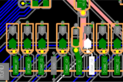
Original SD card routing and detection pins — Original figure source: EN PDF p.18.
From left to right, they are:
DET —- Detection pin
DATA1 —- Data line
DATA0
GND
CLK —- Clock
VCC_SD —- SD card power supply
VCCIO_SD —- Data line IO power supply
CMD —- Command line
DATA3
DATA2
Except for DET/CLK/GND, the other DATA0-3/VCC_SD/VCCIO_SD/CMD must all be around 3.3v, and the minimum should not be lower than 3v; DET pin is low when inserted and high when removed; The voltage of DATA0-3/CMD is supplied by VCCIO_SD, so DATA0-3/CMD must be consistent with VCCIO_SD, and VCC_SD and VCCIO_SD must be consistent (NOTE: SD 3.0 requires VCCIO_SD to be 1.8v);
If the power supply of VCC_SD/VCCIO_SD is a long-term supply, then please ensure that VCC_SD and VCCIO_SD will not collapse when the card is inserted or removed;
(2) SDIO
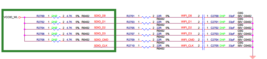
Original SDIO data and command circuitry — Original figure source: EN PDF p.19.
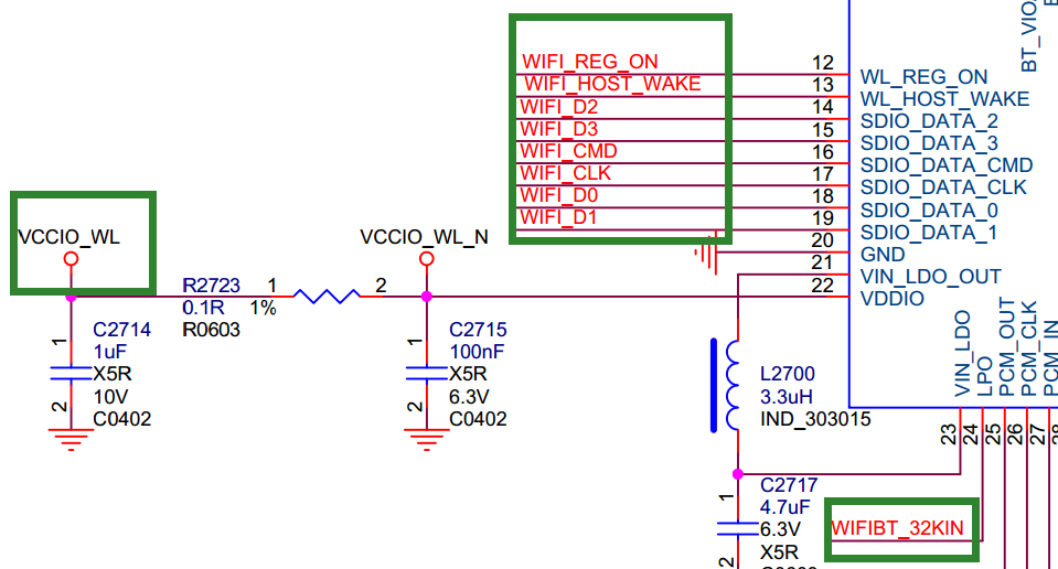
Original WiFi IO supply and control circuitry — Original figure source: EN PDF p.19.
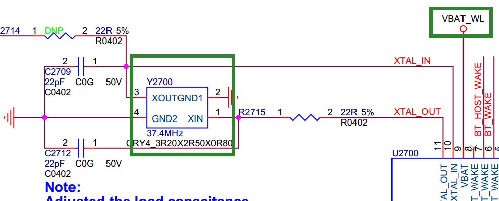
Original WiFi oscillator and supply circuitry — Original figure source: EN PDF p.19.
First, let’s look at the hardware: the main parts are all within the green square
WIFI_D0~3: Data lines, normally high, voltage depends on the voltage of VCCIO_WL;
WIFI_CMD: Command line, normally high, voltage depends on the voltage of VCCIO_WL;
WIFI_CLK: Clock, normally low, voltage depends on the voltage of VCCIO_WL;
VBAT_WL: WIFI module power supply, always high, power supply needs to print 3.3v;
VCCIO_WL: IO power supply for DATA/CMD/CLK, can be 3.3 or 1.8v, but SDIO3.0 must be 1.8v;
WIFI_REG_ON: 3.3v when working normally, 0v when WiFi is turned off;
Two crystal oscillators: 32K and 26M/37.4M, both will have waveform output when working normally;
(3) eMMC
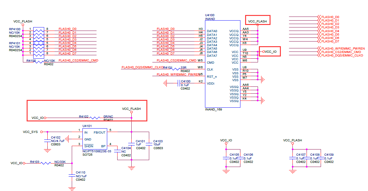
Original eMMC circuitry and supplies — Original figure source: EN PDF p.20.
eMMC valid voltage combinations:
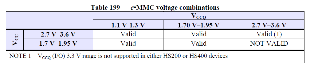
Original eMMC voltage combinations table — Original figure source: EN PDF p.20.
| VCC / VCCQ | 1.1 V–1.3 V | 1.70 V–1.95 V | 2.7 V–3.6 V |
|---|---|---|---|
| 2.7 V–3.6 V | Valid | Valid | Valid (1) |
| 1.7 V–1.95 V | Valid | Valid | NOT VALID |
NOTE 1: The VCCQ (I/O) 3.3 V range is not supported in either HS200 or HS400 devices.
VCC_FLASH corresponds to VCC;
VCC_IO corresponds to VCCQ;
Ensure that the voltages of eMMC_CMD/DATA0~7/VCC_IO are consistent (1.8 or 3.3v);
Ensure that the voltages of VCC_FLASH/VCC_IO remain stable during power-on, operation, or sleep and wake- up, without any collapse or excessive ripple;
If possible, measure the waveform quality of clk, cmd, and data to ensure the waveform is normal.
4.2 Waveform Analysis
The following diagram is the waveform timing chart when the SD card is recognized in mode (the same for sdio and emmc).
A brief explanation of how to identify an SD card: The controller sends out 48clk and carries 48bit data to the SD card, and the SD card needs to respond to the controller with 48clk and 48bit data; as shown in the figure below:
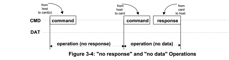
Original command and response timing — Original figure source: EN PDF p.21.
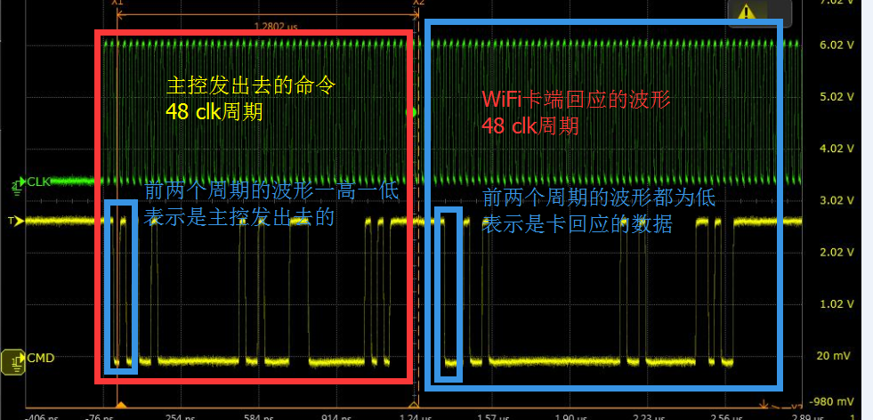
Original host-command and card-response oscilloscope capture — Original figure source: EN PDF p.21.
Green: SDMMC_CLK
Yellow: SDMMC_CMD: SDMMC_CMD remains at a high level when idle;
The waveform sent by the controller: When the first two levels have one high and one low, it indicates the command sent by the controller;
The waveform response from the SD card: When the first two levels have two consecutive low levels, it indicates that the card side has responded;
Secondly, the controller and response generally include 48 bits of data, so 48 clks constitute a complete package. What needs to be confirmed is: after the controller sends out the command package, whether the SD card side responds.
4.3 LOG Analysis
(1) Correctly Identify SD Card LOG
[ 293.194013] mmc1: new high speed SDXC card at address 59b4
[ 293.198185] mmcblk1: mmc1:59b4 00000 59.6 GiB
[ 293.204351] mmcblk1: p1
If such printouts are seen in the kernel, it indicates that the SD card has been correctly identified and has an available partition p1.
If the SD card device is not visible in the user interface or is unusable, please troubleshoot the user-space disk daemon, such as vold.
Additionally, manually verify if the partition is usable
mount -t vfat /dev/block/mmcblk1p1 /mnt
or
mount -t vfat /dev/block/mmcblk1 /mnt
Then go to the mnt directory to see if there are files from the SD card.
(2) No card reading at boot, OK when hot-swapped during runtime: Most likely a power supply issue
For example: Disconnect all power sources and find that there is leakage to VCC_SD card when HDMI is plugged in; or test with an external power supply.
(3) Mount Failure:
If you have seen the LOG in (1), but see the following mount failure LOG
[ 2229.405694] FAT-fs (mmcblk1p1): bogus number of reserved sectors
[ 2229.405751] FAT-fs (mmcblk1p1): Can't find a valid FAT filesystem
Please format the SD card to the FAT32 file system;
Or NTFS: make menuconfig to select support for the NTFS file system;
(4) Probabilistic Non-Recognition:
mmc1: new high speed SD card at address b368
mmcblk1: mmc1:b368 SMI 486 MiB
[mmc1] Data transmission error !!!! MINTSTS: [0x00002000]
dwmmc_rockchip ff0c0000.rksdmmc: data FIFO error (status=00002000)
mmcblk1: error -110 sending status command, retrying
need_retune:0,brq->retune_retry_done:0.
Reduce frequency and increase card detection delay to enhance power stability. If reducing frequency works OK, please check the hardware layout;
&sdmmc {
    card-detect-delay = <1200>;
}
(5) TF card has been mounted, but cannot access the TF card directory, it seems to be a card file system issue, but the card can be accessed under Windows.
Please try to use fsck to repair the TF card.
(6) Hardware issue, IO voltage abnormal
Workqueue: kmmcd mmc_rescan
[<c0013e24>] (unwind_backtrace+0x0/0xe0) from [<c001172c>] (show_stack+0x10/0x14)
[<c001172c>] (show_stack+0x10/0x14) from [<c04fa444>] (dw_mci_set_ios+0x9c/0x21c)
[<c04fa444>] (dw_mci_set_ios+0x9c/0x21c) from [<c04e7748>] (mmc_set_chip_select+0x18/0x1c)
[<c04e7748>] (mmc_set_chip_select+0x18/0x1c) from [<c04ebd5c>] (mmc_go_idle+0x94/0xc4)
[<c04ebd5c>] (mmc_go_idle+0x94/0xc4) from [<c0748d80>] (mmc_rescan_try_freq+0x54/0xd0)
[<c0748d80>] (mmc_rescan_try_freq+0x54/0xd0) from [<c04e85d0>] (mmc_rescan+0x2c4/0x390)
[<c04e85d0>] (mmc_rescan+0x2c4/0x390) from [<c004d738>] (process_one_work+0x29c/0x458)
[<c004d738>] (process_one_work+0x29c/0x458) from [<c004da88>] (worker_thread+0x194/0x2d4)
[<c004da88>] (worker_thread+0x194/0x2d4) from [<c0052fb4>] (kthread+0xa0/0xac)
[<c0052fb4>] (kthread+0xa0/0xac) from [<c000da98>] (ret_from_fork+0x14/0x3c)
1409..dw_mci_set_ios: wait for unbusy timeout....... STATUS = 0x306 [mmc1]
Please check whether the voltage of the CMD line and DATA is at a high level under no-load conditions. And check whether the IO voltage is too low, and whether the IO voltage and power domain configuration are consistent. If it is an SDIO interface, it is recommended to troubleshoot VCCIO_WL voltage, VBAT_WL and WIFI_REG_ON as well as whether the crystal oscillator is normal. Also, try to troubleshoot whether the long wiring leads to poor waveform quality, and test by reducing frequency.
4.4 Other Issues
(1) SD Card Works Normally in 1-Wire Mode but Reports Errors in 4-Wire Mode
Context from CN p.20: this issue is explicitly described as occurring in u-boot; that context is absent from the English heading.
Most SOCs’ SD cards share lines with JTAG, and when no card is inserted, the SOC automatically switches the IO to JTAG functionality.
The EVB reference board is designed according to the SOC requirements, with SD DET low level indicating card insertion. Some customers may modify the schematics to design SD DET high level for card insertion, causing the SOC to misjudge and switch the IO to JTAG functionality.
Solution: Look for the corresponding chip GRF register definition and configure force_jtag as Disable to turn off the automatic switching of JTAG IO.
Reference code for RV1126:
diff --git a/arch/arm/mach-rockchip/rv1126/rv1126.c b/arch/arm/mach-rockchip/rv1126/rv1126.c
index 311310d3f2..29b694df9c 100644
--- a/arch/arm/mach-rockchip/rv1126/rv1126.c
+++ b/arch/arm/mach-rockchip/rv1126/rv1126.c
@@ -544,6 +544,9 @@ void board_debug_uart_init(void)
 #ifndef CONFIG_TPL_BUILD
 int arch_cpu_init(void)
 {
+ struct rv1126_grf * const grf = (void *)GRF_BASE;
+
+ writel(0x00100000, &grf->iofunc_con3);
        /*
         * CONFIG_DM_RAMDISK: for ramboot that without SPL.
         */
(2) SD Card Leakage Causes Abnormal Card Operation
When the IO power supply of the SD module is uncontrollable, if a card is inserted before the 3V3 power supply is provided, leakage may occur from the IO, causing half-level voltage in the SD card’s 3V3 power supply, which can lead to sporadic abnormalities in some cards, manifesting as poor platform compatibility. To solve the leakage issue, the driver will set the SD card IO to pull down when the card is inserted, release the leakage, and then power up the SD card’s 3V3 power supply. After the SD card is powered up, the IO is restored to SD function pins and pull-up is set to avoid a series of abnormalities that may be caused by leakage. Customers with high compatibility requirements for SD cards, please confirm that the SDK kernel’s drivers/mmc/host/dw_mmc.c file includes the submission “mmc: dw_mmc: Add normal and idle pinctrl control”, and refer to the following example to modify your own DTS node, adding an idle mode for pinctrl, which should be configured according to the actual usage of the board with the required clk, cmd, and data lines:
--- a/arch/arm/boot/dts/rv1126-evb-v10.dtsi
+++ b/arch/arm/boot/dts/rv1126-evb-v10.dtsi
    wireless_wlan: wireless-wlan {
@@ -104,9 +99,14 @@ sdmmc_pwren: sdmmc-pwren {
            rockchip,pins = <0 RK_PA1 RK_FUNC_GPIO &pcfg_pull_none>;
        };
+ sdmmc0_idle_pins: sdmmc-idle-pins {
+ rockchip,pins =
+ <3 RK_PA2 RK_FUNC_GPIO &pcfg_pull_down>,
+ <3 RK_PA3 RK_FUNC_GPIO &pcfg_pull_down>,
+ <3 RK_PA4 RK_FUNC_GPIO &pcfg_pull_down>,
+ <3 RK_PA5 RK_FUNC_GPIO &pcfg_pull_down>,
+ <3 RK_PA6 RK_FUNC_GPIO &pcfg_pull_down>,
+ <3 RK_PA7 RK_FUNC_GPIO &pcfg_pull_down>;
+ };
    };
@@ -140,21 +140,18 @@ &sdio {
 };
 &sdmmc {
    max-frequency = <200000000>;
    no-sdio;
    no-mmc;
    bus-width = <4>;
    cap-mmc-highspeed;
    cap-sd-highspeed;
    disable-wp;
- pinctrl-names = "default";
+ pinctrl-names = "normal", "idle";
    pinctrl-0 = <&sdmmc0_clk &sdmmc0_cmd &sdmmc0_det &sdmmc0_bus4>;
+ pinctrl-1 = <&sdmmc0_idle_gpios &sdmmc0_det>;
    vmmc-supply = <&vcc3v3_sd>;
    vqmmc-supply = <&vccio_sd>;
    status = "okay";
 };