
ArmSoM applicability
This is a Rockchip platform reference, not an ArmSoM hardware test report. RK628D/F/H are external bridge chips; use on a particular ArmSoM board depends on exposed signals, power, I2C, GPIO, interrupts, clocks and the target SDK/BSP. The source separately covers Misc, Media and U-Boot drivers, including RK3399, RK356x, RK3588, RK3576 and RK3562 under different kernel branches. This does not establish support on every board. Check the platform and kernel prerequisites for each scenario. No hardware validation was performed.
As explicitly approved, Chinese V2.7 (122 pages) is the common baseline for all three languages. English V2.3 (117 pages) supplies comparison evidence and matching original figures. Content absent or different in that older edition is translated fully from Chinese, including driver porting, signal adjustment/SSC, GVI lane swap and Media configuration. Chinese uses Chinese figures; English and Russian use paired English originals, with source pages in the captions. Editable screenshot transcriptions follow the newer Chinese evidence.
Safety and source discrepancies: register writes, chmod 0666 and setenforce 0 are source debugging examples, not production recommendations. Inconsistent node names, signal-path descriptions and platform scopes are retained and recorded rather than guessed away. Original numbering starts at chapter 2 because the contents chapter is omitted.
Editorial notes · ArmSoM documentation
2. Preface
RK628 has a Display path and an HDMI IN path. In the SDK version, Display is based on DRM and HDMI IN on V4L2. Different frameworks or kernel versions require different adapted drivers, and the SDK version applies only to Rockchip platforms. The For-All driver was introduced to support other platforms and simplify porting. It currently supports RK628D and RK628F/H. For driver patch-version management, see the SDK patch package’s RK628 driver version instructions.
The For-All driver likewise has Display and HDMI IN paths. The Display driver is under drivers/misc/rk628/, supporting RGB / BT1120 / HDMI input and RGB / BT1120 / LVDS / GVI / DSI / HDMI output. The HDMI IN driver is under drivers/media/i2c/rk628/, supporting HDMI input and CSI / BT1120 output. Below, Misc and Media refer to these two independent drivers; each can be compiled and run separately.
2.1 RK628 block diagram
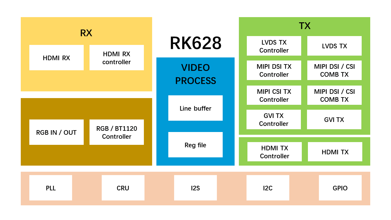
Original technical figure: EN V2.3, p9.
2.2 Typical RK628 hardware design
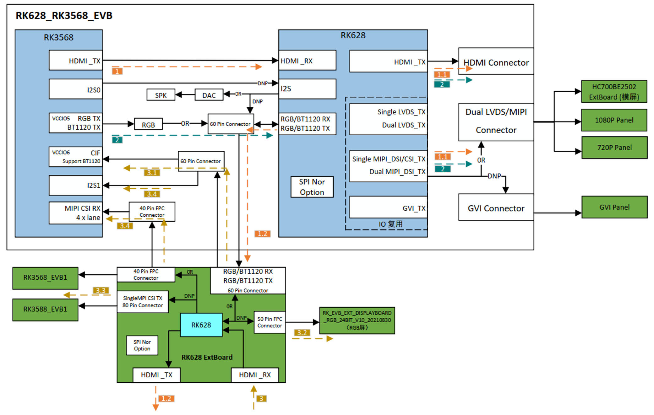
Original technical figure: EN V2.3, p9.
2.3 RK628 main specifications
2.3.1 RK628D main specifications
| Video input interface | Typical resolution | Typical format |
|---|---|---|
| HDMI IN | 4K@30 | YUV420(4K@60) / YUV422 / YUV444 / RGB888 |
| BT1120 IN | 1080P@60 | YUV422 8bit |
| RGB IN | 1080P@60 | RGB888 |
| Video output interface | Typical resolution | Typical format |
| GVI OUT | 4K@60 | RGB888 |
| MIPI CSI | 4K@30 | YUV422 8bit |
| MIPI DSI | 1080P@60 / 2.5K@60 |
RGB888 |
| LVDS OUT | 720P@60 / 1080P@60 |
RGB888 |
| BT1120 OUT | 1080P@60 | YUV422 8bit |
| RGB OUT | 1080P@60 | RGB888 |
| HDMI OUT | 1080P@60 | RGB888/YUV444 8bit |
2.3.2 RK628F main specifications
| Video input interface | Typical resolution | Typical format |
|---|---|---|
| HDMI IN | 4K@60 | RGB888 / YUV422 8bit / YUV422 10bit / YUV420 8bit (> 4k@30Hz) / YUV420 10bit (> 4k@30Hz) |
| BT1120 IN | 1080P@60 | YUV422 8bit |
| RGB IN | 1080P@60 | RGB888 |
| Video output interface | Typical resolution | Typical format |
| GVI OUT | 4K@60 | RGB888 |
| MIPI CSI | Dual MIPI, 4K@60 | YUV422 8bit |
| MIPI DSI | 1080P@60 / 2.5K@60 |
RGB888 |
| LVDS OUT | 720P@60 / 1080P@60 |
RGB888 |
| BT1120 OUT | 1080P@60 | YUV422 8bit |
| RGB OUT | 1080P@60 | RGB888 |
| HDMI OUT | 1080P@60 | RGB888 / YUV444 8bit |
2.3.3 RK628H main specifications
Compared with RK628F, RK628H has no GVI interface.
| Video input interface | Typical resolution | Typical format |
|---|---|---|
| HDMI IN | 4K@60 | RGB888 / YUV422 8bit / YUV422 10bit / YUV420 8bit (> 4k@30Hz) / YUV420 10bit (> 4k@30Hz) |
| BT1120 IN | 1080P@60 | YUV422 8bit |
| RGB IN | 1080P@60 | RGB888 |
| Video output interface | Typical resolution | Typical format |
| MIPI CSI | Dual MIPI, 4K@60 | YUV422 8bit |
| MIPI DSI | 1080P@60 / 2.5K@60 |
RGB888 |
| LVDS OUT | 720P@60 / 1080P@60 |
RGB888 |
| BT1120 OUT | 1080P@60 | YUV422 8bit |
| RGB OUT | 1080P@60 | RGB888 |
| HDMI OUT | 1080P@60 | RGB888 / YUV444 8bit |
2.4 Improvements and optimizations in RK628F/H compared with RK628D
| Functional block | RK628D | RK628F/H |
|---|---|---|
| HDMIRX | Up to 4K@60 YUV420; TMDS CLK 297M | Up to 4K@60 RGB/YUV444; TMDS CLK 594M |
| HDMIRX | Supported frequencies are restricted; a specific resolution must be evaluated and may not be supported | Supports any frequency from 27M to 594M for diverse input resolutions |
| HDMIRX | DVI MODE unsupported | DVI MODE supported |
| HDMIRX | Cannot identify yuv422/yuv420 input video formats | The controller identifies the input video format |
| HDMIRX | RK628D rxphy cannot lock when the source clk lane amplitude is low | This issue is absent |
| HDMIRX | HDMI RX has bit-error detection issues | This issue is absent |
| MIPI CSI |
Single channel, 4 lanes | Dual channel, 8 lanes |
| MIPI CSI |
Maximum 4k@30 yuv422 8bit | Maximum 4k@60 yuv422 8bit |
| GVI | Some panel models fail to light or display incorrectly | The source reports no abnormalities in tests of several commercially available panel models; see Output module configuration → GVI output → RK628F GVI tested model list |
| GVI | Common-source clock required | Common-source clock not required |
| audio | No audio mclk; when using a codec, the host must supply mclk | Can supply mclk |
| audio | HDMI hotplug can cause I2S FIFO overflow and incorrect channel switching | Fixes inconsistent channel order after FIFO overflow |
| csc | Some input/output combinations require color-space conversion or image-format up/downsampling; minor color-detail deviations may occur | This issue is absent |
| hdmi tx | Common-source clock required | rgb2hdmi requires a common clock source; hdmi2hdmi does not |
| Multiple displays | Simultaneous rgb/bt1120 and hdmi tx output at the same resolution | Simultaneous rgb/bt1120, hdmi tx and gvi/dsi/csi/lvds output at the same resolution |
| MCU | No built-in MCU | Built-in MCU |
3. Driver porting instructions
The For-All driver has Display and HDMI IN paths. The Display U-Boot driver is under drivers/video/drm/rk628/ and the kernel driver under drivers/misc/rk628/. It supports RGB / BT1120 / HDMI input and RGB / BT1120 / LVDS / GVI / DSI / HDMI output. The HDMI IN driver is under drivers/media/i2c/rk628/, supporting HDMI input and CSI / DSI / BT1120 output.
Port the following drivers separately as required:
3.1 Display path
3.1.1 U-Boot (drivers/video/drm/rk628)
On Rockchip U-Boot platforms, drivers have been developed for the following RK628F/H display paths to support a fast U-Boot boot logo.
| IC | Display Route | Support |
|---|---|---|
| RK628F/H | HDMI2(Dual)DSI | Supported |
| RK628F/H | HDMI2(Dual)LVDS | Supported |
| RK628F | HDMI2GVI | Supported |
| RK628F/H | HDMI2BT1120/RGB | Supported |
| RK628F/H | BT1120/RGB2(Dual)DSI | Supported |
| RK628F/H | BT1120/RGB2(Dual)LVDS | Supported |
| RK628F | BT1120/RGB2GVI | Supported |
Note: the U-Boot boot-logo driver does not support RK628D because its HDMIRX cannot operate at arbitrary frequencies.
When adding the RK628 Misc driver for the first time, or when no RK628 driver exists under drivers/video/drm, copy the U-Boot Misc RK628 driver source directly into drivers/video/drm and modify the following source files:
drivers/video/drm/rockchip_display.c
drivers/video/drm/Kconfig
drivers/video/drm/Makefile

configs/rk3568_defconfig //以rk3568平台为例
Refer to the following patch:
diff --git a/drivers/video/drm/rockchip_display.c b/drivers/video/drm/rockchip_display.c

index a1cb40a000e..041b8bdd84f 100644
--- a/drivers/video/drm/rockchip_display.c
+++ b/drivers/video/drm/rockchip_display.c
@@ -918,6 +918,23 @@ static int display_enable(struct display_state *state)
      if (state->enabled_at_spl == false)
           rockchip_connector_enable(state);

+#ifdef CONFIG_DRM_ROCKCHIP_RK628

+     /*
+     * trigger .probe helper of U_BOOT_DRIVER(rk628) in ./rk628/rk628.c
+     */
+     struct udevice * dev;
+     int phandle, ret;
+
+     phandle = ofnode_read_u32_default(state->node, "bridge", -1);
+     if (phandle < 0)
+          printf("%s failed to find bridge phandle\n",
ofnode_get_name(state->node));
+
+     ret = uclass_get_device_by_phandle_id(UCLASS_I2C_GENERIC, phandle, &dev);

+     if (ret && ret != -ENOENT)
+          printf("%s:%d failed to get rk628 device ret:%d\n", __func__,
__LINE__, ret);
+
+#endif
+
      if (crtc_state->soft_te)
           crtc_funcs->apply_soft_te(state);
diff --git a/drivers/video/drm/Kconfig b/drivers/video/drm/Kconfig
index ddc65818cba..c5073b9926b 100644
--- a/drivers/video/drm/Kconfig

+++ b/drivers/video/drm/Kconfig
@@ -191,6 +191,13 @@ config DRM_ROCKCHIP_RK618
       Choose this option to enable support for Rockchip RK618 display
       bridge chips driver. say Y to enable its driver.

+config DRM_ROCKCHIP_RK628
+     bool "Rockchip RK628 display bridge driver"
+     depends on DRM_ROCKCHIP
+     help
+      Choose this option to enable support for Rockchip RK628 display
+      bridge chips driver. say Y to enable its driver.
+
diff --git a/drivers/video/drm/Makefile b/drivers/video/drm/Makefile
index ea4219d9cf6..f11a8ff4885 100644

--- a/drivers/video/drm/Makefile
+++ b/drivers/video/drm/Makefile
@@ -36,6 +36,7 @@ obj-$(CONFIG_DRM_ROCKCHIP_RGB) += rockchip_rgb.o
 obj-$(CONFIG_DRM_ROCKCHIP_PANEL) += rockchip_panel.o
 obj-$(CONFIG_DRM_ROHM_BU18XL82) += rohm-bu18tl82.o rohm-bu18rl82.o
 obj-$(CONFIG_DRM_ROCKCHIP_RK618) += rk618.o rk618_lvds.o rk618_dsi.o
+obj-$(CONFIG_DRM_ROCKCHIP_RK628) += rk628/
 obj-$(CONFIG_DRM_ROCKCHIP_RK1000) += rk1000.o rk1000_tve.o
 obj-$(CONFIG_DRM_ROCKCHIP_SAMSUNG_MIPI_DCPHY) += samsung_mipi_dcphy.o
 obj-$(CONFIG_DRM_SII902X) += sii902x.o
diff --git a/configs/rk3568_defconfig b/configs/rk3568_defconfig
index acd1fb18169..94f1050eb4f 100644
--- a/configs/rk3568_defconfig

+++ b/configs/rk3568_defconfig
@@ -224,3 +224,4 @@ CONFIG_RK_AVB_LIBAVB_USER=y
 CONFIG_OPTEE_CLIENT=y
 CONFIG_OPTEE_V2=y
 CONFIG_OPTEE_ALWAYS_USE_SECURITY_PARTITION=y
+CONFIG_DRM_ROCKCHIP_RK628=y
Finally, to enable the U-Boot boot logo, add the following DTS configuration:
For RGB input:
 &route_rgb {
      status = "okay";

+
+     bridge = <&i2c2_rk628>;
 };
For HDMI input:
&route_hdmi {
      status = "okay";
+

+     bridge = <&i2c2_rk628>;
      force-bus-format = <MEDIA_BUS_FMT_RGB888_1X24>;
      force-output;
      force_timing{
To avoid flicker when transitioning from the U-Boot logo to the kernel logo, ensure that the kernel contains the patch with the following commit information:
misc: rk628: add support uboot logo

Type: Function

Redmine ID: #496880 #491750
Associated modifications: NULL
Test: NULL

Change-Id: I311e2c9682f835b377ea9082e1d3a88688167172
Signed-off-by: Guochun Huang <hero.huang@rock-chips.com>
3.1.2 Kernel (drivers/misc/rk628)
On a Rockchip kernel platform, when adding RK628 Misc for the first time or when drivers/misc has no RK628 driver, copy the kernel Misc RK628 source directly into drivers/misc. Modify drivers/misc/Kconfig, drivers/misc/Makefile and arch/arm64/configs/rockchip_defconfig to add RK628 compilation. Refer to this patch:
diff --git a/drivers/misc/Kconfig b/drivers/misc/Kconfig
index 276c7c4fef15..8481b9613bc9 100644
--- a/drivers/misc/Kconfig

+++ b/drivers/misc/Kconfig
@@ -5,6 +5,8 @@

 menu "Misc devices"

+source "drivers/misc/rk628/Kconfig"
+
 config RK803
      tristate "RK803"
      default n
diff --git a/drivers/misc/Makefile b/drivers/misc/Makefile
index b296e760fd47..14642c54a2bc 100644

--- a/drivers/misc/Makefile
+++ b/drivers/misc/Makefile
@@ -3,6 +3,7 @@
 # Makefile for misc devices that really don't fit anywhere else.
 #

+obj-y                 += rk628/
 obj-$(CONFIG_RK803)   += rk803.o
 obj-y                 += rockchip/
 obj-$(CONFIG_LT7911D_FB_NOTIFIER) += lt7911d-fb-notifier.o
diff --git a/arch/arm64/configs/rockchip_defconfig b/arch/arm64/configs/rockchip_defconfig
index 28340b4bdfae..dbb7d9e55b62 100644

--- a/arch/arm64/configs/rockchip_defconfig
+++ b/arch/arm64/configs/rockchip_defconfig
@@ -294,6 +294,8 @@ CONFIG_BLK_DEV_LOOP_MIN_COUNT=16
 CONFIG_BLK_DEV_RAM=y
 CONFIG_BLK_DEV_RAM_SIZE=8192
 CONFIG_BLK_DEV_NVME=y
+CONFIG_RK628_MISC=y
+CONFIG_RK628_MISC_HDMITX=y
 CONFIG_LT7911D_FB_NOTIFIER=y
 CONFIG_SRAM=y
 CONFIG_UID_SYS_STATS=y
@@ -557,7 +559,6 @@ CONFIG_ROCKCHIP_THERMAL=y

 CONFIG_WATCHDOG=y
 CONFIG_DW_WATCHDOG=y
 CONFIG_MFD_RK618=y
-CONFIG_MFD_RK628=y
 CONFIG_MFD_RK630_I2C=y
 CONFIG_MFD_RK806_I2C=y
 CONFIG_MFD_RK806_SPI=y
@@ -640,7 +641,6 @@ CONFIG_ROCKCHIP_LVDS=y
 CONFIG_ROCKCHIP_RGB=y
 CONFIG_ROCKCHIP_DW_HDCP2=y
 CONFIG_DRM_ROCKCHIP_RK618=y
-CONFIG_DRM_ROCKCHIP_RK628=y
CONFIG_DRM_PANEL_SIMPLE=y
CONFIG_DRM_PANEL_MAXIM_MAX96752F=y
CONFIG_DRM_PANEL_MAXIM_MAX96772=y
Important: CONFIG_MFD_RK628 and CONFIG_DRM_ROCKCHIP_RK628 select older RK628 drivers and must be removed from rockchip_defconfig.
Misc drivers are compiled by default; DTS selects which driver runs.
3.2 HDMI IN path (drivers/media/i2c/rk628)
For kernels before 5.10, use the rk628_for-all patch package. For kernel 5.10, use kernel_5.10_rk628_media_patch. Copy the Media RK628 driver into drivers/media/i2c/rk628/ and modify drivers/media/i2c/Kconfig, drivers/media/i2c/Makefile and arch/arm64/configs/rockchip_defconfig to compile RK628. Refer to the patch below:
diff --git a/drivers/media/i2c/Kconfig b/drivers/media/i2c/Kconfig
index f3273756c612..609bb5e3db07 100644
--- a/drivers/media/i2c/Kconfig

+++ b/drivers/media/i2c/Kconfig
@@ -414,6 +414,8 @@ config VIDEO_OTP_EEPROM
      help
       This driver supports OTP load from eeprom.

+source "drivers/media/i2c/rk628/Kconfig"
+
 config VIDEO_SAA7110
      tristate "Philips SAA7110 video decoder"
      depends on VIDEO_V4L2 && I2C
diff --git a/drivers/media/i2c/Makefile b/drivers/media/i2c/Makefile
index 26edd6f7590e..d6f4128b19a5 100644

--- a/drivers/media/i2c/Makefile
+++ b/drivers/media/i2c/Makefile
@@ -141,6 +141,7 @@ obj-$(CONFIG_VIDEO_ML86V7667) += ml86v7667.o
 obj-$(CONFIG_VIDEO_OV2659) += ov2659.o
 obj-$(CONFIG_VIDEO_TC358743) += tc358743.o
 obj-$(CONFIG_VIDEO_TC35874X) += tc35874x.o
+obj-$(CONFIG_VIDEO_RK628) += rk628/
 obj-$(CONFIG_VIDEO_AR0230) += ar0230.o
 obj-$(CONFIG_VIDEO_GC02M2) += gc02m2.o
 obj-$(CONFIG_VIDEO_GC08A3) += gc08a3.o
diff --git a/arch/arm64/configs/rockchip_defconfig b/arch/arm64/configs/rockchip_defconfig
index 95ad81b12a69..c66f67ecd0c2 100644

--- a/arch/arm64/configs/rockchip_defconfig
+++ b/arch/arm64/configs/rockchip_defconfig
@@ -567,6 +567,8 @@ CONFIG_VIDEO_ROCKCHIP_ISPP=y
 CONFIG_VIDEO_ROCKCHIP_HDMIRX=y
 CONFIG_VIDEO_LT6911UXC=y
 CONFIG_VIDEO_LT7911D=y
+CONFIG_VIDEO_RK628_CSI=y
+CONFIG_VIDEO_RK628_BT1120=y
 CONFIG_VIDEO_TC35874X=y
 CONFIG_VIDEO_GC0312=y
 CONFIG_VIDEO_GC2145=y
Media drivers are compiled by default; DTS selects which driver runs.
4. I2C communication between the SoC and RK628
The SoC communicates with RK628 over I2C. The typical 7-bit RK628 address is 0x50. When multiple RK628 devices share an I2C bus, change their I2C addresses using RK628 GPIOs as follows:
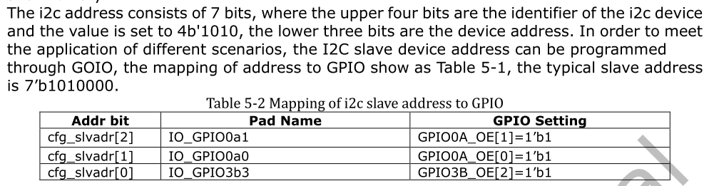
Original technical figure: EN V2.3, p13.
Text in the figure: the I2C address has 7 bits. The upper four identify the device and are set to 4’b1010; the lower three are the device address. GPIOs can program the slave address for different scenarios. The typical address is 7’b1010000.
| Addr bit | Pad Name | GPIO Setting |
|---|---|---|
| cfg_slvadr[2] | IO_GPIO0a1 | GPIO0A_OE[1]=1’b1 |
| cfg_slvadr[1] | IO_GPIO0a0 | GPIO0A_OE[0]=1’b1 |
| cfg_slvadr[0] | IO_GPIO3b3 | GPIO3B_OE[2]=1’b1 |
For example, slave addresses 0x50 and 0x51:
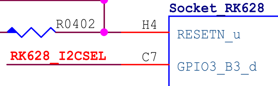
Original technical figure: EN V2.3, p13.

Original technical figure: EN V2.3, p13.
| I2C SEL | I2C ADDR |
|---|---|
| 0 | 7’b1010000 (0x50) |
| 1 | 7’b1010001 (0x51) |
Keep GPIO0a0 and GPIO0a1 low. With GPIO3b3 high, the slave address is 0x51 (7’b1010001); with GPIO3b3 low, it is 0x50 (7’b1010000).
5. Misc
5.1 MISC driver introduction
The RK628 Misc driver implements the RK628 Display path for display-protocol conversion. Inputs are RGB, BT1120 or HDMI; outputs are LVDS, GVI, DSI, RGB, BT1120 or HDMI.
5.1.1 Driver porting
See Driver porting instructions → Display path.
5.1.2 U-Boot driver directory structure
drivers/video/drm/rk628/
├── Makefile

├── panel.c
├── panel.h
├── rk628.c
├── rk628_combtxphy.c
├── rk628_combtxphy.h
├── rk628_cru.c
├── rk628_cru.h
├── rk628_dsi.c
├── rk628_dsi.h
├── rk628_gvi.c
├── rk628_gvi.h
├── rk628.h

├── rk628_hdmirx.c
├── rk628_hdmirx.h
├── rk628_hdmitx.h
├── rk628_lvds.c
├── rk628_lvds.h
├── rk628_post_process.c
├── rk628_post_process.h
├── rk628_rgb.c
└── rk628_rgb.h
5.1.3 Kernel driver directory structure
drivers/misc/rk628/
├── Kconfig
├── Makefile

├── panel.c
├── panel.h
├── rk628.c
├── rk628_combrxphy.c
├── rk628_combrxphy.h
├── rk628_combtxphy.c
├── rk628_combtxphy.h
├── rk628_config.c

├── rk628_config.h
├── rk628_cru.c
├── rk628_cru.h
├── rk628_csi.c
├── rk628_csi.h
├── rk628_dsi.c
├── rk628_dsi.h
├── rk628_efuse.c
├── rk628_efuse.h
├── rk628_gpio.h
├── rk628_grf.h
├── rk628_gvi.c

├── rk628_gvi.h
├── rk628.h
├── rk628_hdmirx.c
├── rk628_hdmirx.h
├── rk628_hdmitx.c
├── rk628_hdmitx.h
├── rk628_lvds.c
├── rk628_lvds.h
├── rk628_pinctrl.c
├── rk628_pinctrl.h
├── rk628_post_process.c
├── rk628_post_process.h
├── rk628_rgb.c

├── rk628_rgb.h
5.1.4 DTS configuration overview
Example: RGB → DSI.
&i2c2 {
   clock-frequency = <400000>;

   status = "okay";

   i2c2_rk628: rk628@50 {
      compatible = "rockchip,rk628";
      reg = <0x50>;
      interrupt-parent = <&gpio0>;
      interrupts = <20 IRQ_TYPE_LEVEL_HIGH>;
      enable-gpios = <&gpio0 RK_PC1 GPIO_ACTIVE_HIGH>;
      reset-gpios = <&gpio2 RK_PA2 GPIO_ACTIVE_LOW>;
      pinctrl-names = "default";
      pinctrl-0 = <&rk628_reset>;
      status = "okay";
   };

};

&pinctrl {
   rk628 {
      rk628_reset: rk628-reset {
         rockchip,pins = <2 RK_PA2 RK_FUNC_GPIO &pcfg_pull_none>;
      };

   };
};

&i2c2_rk628 {
   /* soc_24M optional */
   pinctrl-names = "default";
   pinctrl-0 = <&rk628_reset &refclk_pins>;
   assigned-clocks = <&pmucru CLK_WIFI>;
   assigned-clock-rates = <24000000>;
   clocks = <&pmucru CLK_WIFI>;
   clock-names = "soc_24M";


   panel-backlight = <&backlight>;
   panel-power-supply = <&vcc3v3_lcd0_n>;
   panel-enable-gpios = <&gpio2 RK_PC6 GPIO_ACTIVE_HIGH>;

   panel-reset-delay-ms = <10>;
   panel-enable-delay-ms = <10>;
   panel-prepare-delay-ms = <60>;
   panel-unprepare-delay-ms = <10>;
   panel-disable-delay-ms = <60>;
   panel-init-delay-ms = <60>;

   rk628-rgb-in;
   rk628-dsi-out {

      dsi,eotp;
      dsi,video-mode;
      dsi,format = "rgb888";
      dsi,lanes = <4>;
      status = "okay";

      rk628-panel {
         panel-init-sequence = [
            05 78 01 11
            05 78 01 29
         ];


         panel-exit-sequence = [
            05 00 01 28
            05 00 01 10
         ];
      };
   };

   display-timings {
      src-timing {
         clock-frequency = <148500000>;
         hactive = <1920>;
         vactive = <1080>;
         hfront-porch = <88>;

         hsync-len = <44>;
         hback-porch = <148>;
         vfront-porch = <4>;
         vsync-len = <5>;
         vback-porch = <36>;
         hsync-active = <1>;

         vsync-active = <1>;
         de-active = <0>;
         pixelclk-active = <0>;
      };

      dst-timing {
         clock-frequency = <148500000>;
         hactive = <1920>;
         vactive = <1080>;
         hfront-porch = <88>;
         hsync-len = <44>;
         hback-porch = <148>;

         vfront-porch = <4>;
         vsync-len = <5>;
         vback-porch = <36>;
         hsync-active = <1>;
         vsync-active = <1>;
         de-active = <0>;
         pixelclk-active = <0>;
      };
   };
};
5.2 Core driver configuration
5.2.1 RK628 node configuration
The SoC communicates with RK628 over I2C. Taking RK3568 as an example, add an RK628 node (i2c2_rk628: rk628@50) under the DTS I2C node i2c2:
&i2c2 {
   clock-frequency = <400000>;

   status = "okay";

   i2c2_rk628: rk628@50 {
      compatible = "rockchip,rk628";
      reg = <0x50>;
      enable-gpios = <&gpio0 RK_PC1 GPIO_ACTIVE_HIGH>;
      reset-gpios = <&gpio2 RK_PA2 GPIO_ACTIVE_LOW>;
      pinctrl-names = "default";
      pinctrl-0 = <&rk628_reset>;
      status = "okay";
   };
};


&pinctrl {
   rk628 {
      rk628_reset: rk628-reset {
         rockchip,pins = <2 RK_PA2 RK_FUNC_GPIO &pcfg_pull_none>;
      };
   };
};
RK628 node properties:
| Property | Description | Option Value |
|---|---|---|
| compatible | compatible | Set RK628 Misc compatible to “rockchip,rk628” |
| reg | RK628 I2C slave address | 0x50/0x51, according to hardware |
| enable-gpios | RK628 enable GPIO reference | Configure according to hardware |
| reset-gpios | RK628 reset GPIO reference | Configure according to hardware |
| pinctrl-names | Set the RK628 reset pin mux to GPIO | Configure according to hardware |
| pinctrl-0 | Set the RK628 reset pin mux to GPIO | Configure according to hardware |
5.2.2 24 MHz working clock
The RK628 24 MHz working clock can come from an external 24M crystal or a SoC 24 MHz CLK pin. When using an external crystal, the following configuration can be omitted.
Note that RK628D HDMI / GVI OUT paths and the RK628F/H RGB → HDMI path require the SoC’s 24 MHz CLK output as the RK628 working clock so that the clocks share a source. An external 24M crystal may cause display problems in these cases. RK628F/H improves common-source clock handling: the TMDS CLK detected by HDMI RX is used as the CRU PLL reference. Thus HDMI IN paths do not require the SoC’s 24 MHz CLK as a reference.
For RK3568 (other Rockchip platforms are covered in RK628 24M crystal clock from another SoC), several pins can output 24 MHz, including REF_CLKOUT (clk_wifi / gpio0_a0), CAM_CLKOUT1 (clk_cam1_out / gpio4_b0) and ETH_REFCLK_25M_M0 (clk_mac1_out / gpio3_b0). The first is used below.
1. Reference this configuration in the DTS RK628 node:
&i2c2_rk628 {
   /* soc_24M optional */
   pinctrl-names = "default";

   pinctrl-0 = <&rk628_reset &refclk_pins>;
   assigned-clocks = <&pmucru CLK_WIFI>;
   assigned-clock-rates = <24000000>;
   clocks = <&pmucru CLK_WIFI>;
   clock-names = "soc_24M";
   ......
};
2. The following configuration is already provided in rk3568-pinctrl.dtsi:
&pinctrl {
   ......
   refclk {

      /omit-if-no-ref/
      refclk_pins: refclk-pins {
         rockchip,pins =
           /* refclk_ou */
           <0 RK_PA0 1 &pcfg_pull_none>;
      };
   };
   ......
};
24 MHz CLK properties:
| Property | Description | Option Value |
|---|---|---|
| pinctrl-names | Set the refclk pin mux | Configure according to hardware. This overrides the RK628 properties above, so also include the rk628_reset reference |
| pinctrl-0 | Set the refclk pin mux | Configure according to hardware. This overrides the RK628 properties above, so also include the rk628_reset reference |
| assigned-clocks | Clock reference assigned to RK628 | Configure according to hardware |
| assigned-clock-rates | Clock rate assigned to RK628 (Hz) | <24000000> |
| clocks | List of referenced clock handles | Configure according to hardware |
| clock-names | Name assigned to the clock | “soc_24M” |
5.2.3 Selecting input and output modules
In the DTS RK628 node, configure the required input/output module properties (boolean) or nodes. Configure the corresponding functional parameters in each module node:
&i2c2_rk628 {
   ......

   rk628-rgb-in;
   rk628-dsi-out {
      ......
   };
   ......
};
For RGB → DSI, set the “rk628-rgb-in;” property to select RGB input and the “rk628-dsi-out” node to select DSI output. Current Misc input modules are RGB IN, BT1120 IN and HDMI IN; output modules are LVDS, GVI, DSI and HDMI. See Input module configuration and Output module configuration for details.
5.2.4 Panel configuration
In the DTS RK628 node, configure backlight, supply, reset pin, power-up timing and display timing according to the panel specification. This configuration is not required for an HDMITX path:
&i2c2_rk628 {
   ......

   panel-backlight = <&backlight>;
   panel-power-supply = <&vcc3v3_lcd0_n>;
   panel-enable-gpios = <&gpio2 RK_PC6 GPIO_ACTIVE_HIGH>;

   panel-reset-delay-ms = <10>;
   panel-enable-delay-ms = <10>;
   panel-prepare-delay-ms = <60>;
   panel-unprepare-delay-ms = <10>;
   panel-disable-delay-ms = <60>;
   panel-init-delay-ms = <60>;
   ......
   display-timings {
      src-timing {

         clock-frequency = <148500000>;
         hactive = <1920>;
         vactive = <1080>;
         hfront-porch = <88>;
         hsync-len = <44>;
         hback-porch = <148>;
         vfront-porch = <4>;
         vsync-len = <5>;
         vback-porch = <36>;
         hsync-active = <1>;
         vsync-active = <1>;
         de-active = <0>;

         pixelclk-active = <0>;
      };

      dst-timing {
         clock-frequency = <148500000>;
         hactive = <1920>;
         vactive = <1080>;
         hfront-porch = <88>;
         hsync-len = <44>;
         hback-porch = <148>;
         vfront-porch = <4>;
         vsync-len = <5>;
         vback-porch = <36>;

         hsync-active = <1>;
         vsync-active = <1>;
         de-active = <0>;
         pixelclk-active = <0>;
      };
   };
   ......
};
Panel properties:
| Property | Description | Option Value |
|---|---|---|
| panel-enable-gpios | Panel enable GPIO reference [optional] | Configure according to hardware |
| panel-reset-gpios | Panel reset GPIO reference [optional] | Configure according to hardware |
| panel-backlight | Panel backlight [optional] | Configure according to hardware |
| panel-reset-delay-ms | Panel power-up timing | See the panel specification |
| panel-enable-delay-ms | Panel power-up timing | See the panel specification |
| panel-prepare-delay-ms | Panel power-up timing | See the panel specification |
| panel-unprepare-delay-ms | Panel power-up timing | See the panel specification |
| panel-disable-delay-ms | Panel power-up timing | See the panel specification |
| panel-init-delay-ms | Panel power-up timing | See the panel specification |
| src-timing | SoC-to-RK628 display timing node | Scale against dst-timing separately in the horizontal and vertical directions |
| dst-timing | Panel display timing node | See the panel specification |
| clock-frequency | Display timing | See the panel specification and actual scaler configuration |
| hactive | Display timing | See the panel specification and actual scaler configuration |
| vactive | Display timing | See the panel specification and actual scaler configuration |
| hfront-porch | Display timing | See the panel specification and actual scaler configuration |
| hback-porch | Display timing | See the panel specification and actual scaler configuration |
| hsync-len | Display timing | See the panel specification and actual scaler configuration |
| vfront-porch | Display timing | See the panel specification and actual scaler configuration |
| vback-porch | Display timing | See the panel specification and actual scaler configuration |
| vsync-len | Display timing | See the panel specification and actual scaler configuration |
| hsync-active | Display timing | See the panel specification and actual scaler configuration |
| vsync-active | Display timing | See the panel specification and actual scaler configuration |
| de-active | Display timing | See the panel specification and actual scaler configuration |
| pixelclk-active | Display timing | See the panel specification and actual scaler configuration |
When scaling between different input and output resolutions, put the input timing in src-timing and the output timing in dst-timing. The active display and blanking portions must use the same scaling ratio:
src: hactive / dst: hactive = src: hblanking / dst: hblanking
src: vactive / dst: vactive = src: vblanking / dst: vblanking
hblanking = hfront-porch + hback-porch + hsync-len

vblanking = vfront-porch + vback-porch + vsync-len
The frame rate must also remain unchanged before and after scaling.
src: clock-frequency / (htotal * vtotal) = dst: clock-frequency / (htotal *
vtotal)
htotal = hactive + hfront-porch + hback-porch + hsync-len

vtotal = vactive + vfront-porch + vback-porch + vsync-len
If input and output resolutions are identical, use the same target timing in src-timing and dst-timing.
For two DSI panels of the same resolution, or two LVDS panels of the same resolution, multiply clock-frequency, hactive, hfront-porch, hback-porch and hsync-len in both src-timing and dst-timing by 2 relative to the original single-panel configuration.
5.2.5 Different display-path combinations
Refer to the following DTS examples. Details of each path are in Combinations currently supported by DTS.
arch/arm64/boot/dts/rockchip/rk3568-evb-rk628-hdmi2bt1120-ddr4-v10.dts
arch/arm64/boot/dts/rockchip/rk3568-evb-rk628-hdmi2dsi-ddr4-v10.dts
arch/arm64/boot/dts/rockchip/rk3568-evb-rk628-hdmi2dsi-dual-ddr4-v10.dts

arch/arm64/boot/dts/rockchip/rk3568-evb-rk628-hdmi2gvi-ddr4-v10.dts
arch/arm64/boot/dts/rockchip/rk3568-evb-rk628-hdmi2lvds-ddr4-v10.dts
arch/arm64/boot/dts/rockchip/rk3568-evb-rk628-hdmi2lvds-dual-ddr4-v10.dts
arch/arm64/boot/dts/rockchip/rk3568-evb-rk628-rgb2dsi-ddr4-v10.dts
arch/arm64/boot/dts/rockchip/rk3568-evb-rk628-rgb2gvi-ddr4-v10.dts
arch/arm64/boot/dts/rockchip/rk3568-evb-rk628-rgb2hdmi-ddr4-v10.dts
arch/arm64/boot/dts/rockchip/rk3568-evb-rk628-rgb2lvds-ddr4-v10.dts
arch/arm64/boot/dts/rockchip/rk3568-evb-rk628-rgb2lvds-dual-ddr4-v10.dts
5.2.6 Output-signal adjustment
5.2.6.1 GVI / LVDS / MIPI TX signal adjustment
1. The comb_tx voltage and pre-emphasis registers independently control 10 lane pairs (tx0 ~ tx9 in the register configuration). Their interface mapping is:
| COMB_TX | GVI | LVDS / MIPI |
|---|---|---|
| TX0 P/N | GVI_TX0 P/N | L/M0_TX0 P/N |
| TX1 P/N | GVI_TX1 P/N | L/M0_TX1 P/N |
| TX2 P/N | / | L/M0_TXCLK P/N |
| TX3 P/N | GVI_TX2 P/N | L/M0_TX2 P/N |
| TX4 P/N | GVI_TX3 P/N | L/M0_TX3 P/N |
| TX5 P/N | GVI_TX4 P/N | L/M1_TX0 P/N |
| TX6 P/N | GVI_TX5 P/N | L/M1_TX1 P/N |
| TX7 P/N | / | L/M1_TXCLK P/N |
| TX8 P/N | GVI_TX6 P/N | L/M1_TX2 P/N |
| TX9 P/N | GVI_TX7 P/N | L/M1_TX3 P/N |
2. Test signal adjustments by writing registers directly. These settings do not survive a reboot; for a permanent configuration, modify the patch below.
# 1. 电压缩放 N=0(75%), 1/2(100%), 3(125%) (通常无需调节)
# echo 0x90004 $val > /d/rk628/2-0050/registers/combtxphy

# $val:
#   tx0[Bit1:0], tx1[Bit3:2], tx2[Bit5:4], tx3[Bit7:6], tx4[Bit9:8]
#   tx5[Bit17:16], tx6[Bit19:18], tx7[Bit21:20], tx8[Bit23:22], tx9[Bit25:24]
# 以 1(100%) 为例:
echo 0x90004 0x01550155 > /d/rk628/2-0050/registers/combtxphy

# 2. 电压调节 N=0~7
# echo 0x90008 $val > /d/rk628/2-0050/registers/combtxphy
# $val:
#   tx0[Bit2:0], tx1[Bit5:3], tx2[Bit8:6], tx3[Bit11:9], tx4[Bit14:12]
#   tx5[Bit18:16], tx6[Bit21:19], tx7[Bit24:22], tx8[Bit27:25], tx9[Bit30:28]
# 以 3 档为例:
echo 0x90008 0x36db36db > /d/rk628/2-0050/registers/combtxphy


# 3. 预加重调节 N=0~9
# echo 0x9000c $val > /d/rk628/2-0050/registers/combtxphy
# $val: tx0[Bit3:0], tx1[Bit7:4], tx2[Bit11:8], tx3[Bit15:12], tx4[Bit19:16]
# echo 0x90010 $val > /d/rk628/2-0050/registers/combtxphy
# $val: tx5[Bit3:0], tx6[Bit7:4], tx7[Bit11:8], tx8[Bit15:12], tx9[Bit19:16]
# 以 5 档为例:
echo 0x9000c 0x55555 > /d/rk628/2-0050/registers/combtxphy
echo 0x90010 0x55555 > /d/rk628/2-0050/registers/combtxphy
3. Output-signal adjustment patch, using GVI TX as the example. Refer to the settings above.
diff --git a/drivers/misc/rk628/rk628_combtxphy.c b/drivers/misc/rk628/rk628_combtxphy.c

index 3387d8bd73b9..70d7a5422a35 100644
--- a/drivers/misc/rk628/rk628_combtxphy.c
+++ b/drivers/misc/rk628/rk628_combtxphy.c
@@ -139,6 +139,14 @@ static void rk628_combtxphy_gvi_power_on(struct rk628
*rk628)
      usleep_range(100, 200);

      rk628_i2c_update_bits(rk628, COMBTXPHY_CON0,
                      SW_TX_IDLE_MASK, 0);
+
+     // amplitude scale
+     rk628_i2c_write(rk628, COMBTXPHY_CON1, 0x01550155);
+     // amplitude level
+     rk628_i2c_write(rk628, COMBTXPHY_CON2, 0x36db36db);
+     // emphasis level
+     rk628_i2c_write(rk628, COMBTXPHY_CON3, 0x00055555);
+     rk628_i2c_write(rk628, COMBTXPHY_CON4, 0x00055555);
 }


 void rk628_combtxphy_power_on(struct rk628 *rk628)
5.2.6.2 HDMI TX signal adjustment
1. Test signal adjustments by writing registers directly. These settings do not survive a reboot; for permanent settings, modify the patch below.
# 1. 驱动强度调节
# echo 0x70388 $val > /d/rk628/2-0050/registers/hdmi

# $val: clk_driver_strength[Bit7:4], data_driver_strength[Bit3:0]
#      范围(强度从低到高):0x0  ~ 0xF
# 以 0x8 为例:
echo 0x70388 0x88 > /d/rk628/2-0050/registers/hdmi

# 2. 预加重调节
# echo 0x7038c $val > /d/rk628/2-0050/registers/hdmi
# $val: pre_emphasis_strength[Bit6:4]
#      范围(强度从低到高):0x0  ~ 0x7
#     clk_pre_driver_strength[Bit3:2], data_pre_driver_strength[Bit1:0]
#      范围(强度从低到高):0x0  ~ 0x3
# 以 pre_emphasis_strength = 0x3, clk/data_pre_driver_strength = 0x3 为例:

echo 0x7038c 0x3f > /d/rk628/2-0050/registers/hdmi
2. HDMI output-signal adjustment patch. This example divides (74.25M, 165M] into (74.25M, 148.5M] and (148.5M, 165M].
{ upper frequency-band limit, pre-emphasis, drive strength }: refer to the settings above.
diff --git a/drivers/misc/rk628/rk628_hdmitx.c b/drivers/misc/rk628/rk628_hdmitx.c
index f28b78a6b525..2120cf504ebe 100644

--- a/drivers/misc/rk628/rk628_hdmitx.c
+++ b/drivers/misc/rk628/rk628_hdmitx.c
@@ -231,6 +231,7 @@ static void rk628_hdmi_sys_power(struct rk628_hdmi *hdmi,
bool enable)
 static struct rk628_hdmi_phy_config rk628_hdmi_phy_config[] = {
      /* pixelclk pre-emp vlev */
      { 74250000, 0x3f, 0x88 },
+     { 148500000, 0x3f, 0x88 },
      { 165000000, 0x3f, 0x88 },
      { ~0UL,  0x00, 0x00 }
 };
5.2.6.3 SSC (spread spectrum)
1. Apply global spread spectrum to CPLL to produce spread-spectrum output in a GVI TX scenario.
# echo 0xc000c $((val | 0xffff0000)) > /d/rk628/2-0050/registers/cru
# $val:
#   ssmod_spread[Bit12:8](Spread amplitude / 0.1%)

#   ssmod_divval[Bit7:4](Divider required to set the modulation frequency)
#   参数说明⻅下方描述
# 例 ssmod_spread = 3, ssmod_divval = 6 (推荐值):
echo 0xc000c 0xffff0360 > /d/rk628/2-0050/registers/cru
(1) ssmod_spread [Bit12:8]: modulation depth. Generally it should not exceed 5000 ppm. Since actual environments are complex, measurements take precedence: the measured value must not exceed 0.3%; the recommended setting is 0.3%. That is, spread = 3.
(2) ssmod_divval [Bit7:4]: modulation frequency, indicating how quickly the frequency changes. The formula is:
f_mod = f_CLKSSCG / (128 × divval); f_CLKSSCG = f_PFD = f_REF / refdiv.
Here f_mod is the modulation frequency, which should be 30–33 kHz; f_REF is the reference (crystal) clock; refdiv defaults to 1. The recommended setting is divval = 6, giving f_mod = 31.25 kHz.
2. SSC patch, using GVI TX as the example. Refer to the settings above.
diff --git a/drivers/misc/rk628/rk628_combtxphy.c b/drivers/misc/rk628/rk628_combtxphy.c

index 3387d8bd73b9..70d7a5422a35 100644
--- a/drivers/misc/rk628/rk628_combtxphy.c
+++ b/drivers/misc/rk628/rk628_combtxphy.c
@@ -139,6 +139,9 @@ static void rk628_combtxphy_gvi_power_on(struct rk628 *rk628)
      usleep_range(100, 200);
      rk628_i2c_update_bits(rk628, COMBTXPHY_CON0,
                      SW_TX_IDLE_MASK, 0);
+
+     // ssmod
+     rk628_i2c_write(rk628, CRU_CPLL_CON3, 0xffff0360);
 }
void rk628_combtxphy_power_on(struct rk628 *rk628)
5.3 Input module configuration
5.3.1 RGB input
5.3.1.1 RGB input configuration
1. Add the boolean property “rk628-rgb-in;” to the DTS RK628 node:
&i2c2_rk628 {
   ......

   rk628-rgb-in;
   ......
};
RGB IN / RGB OUT / BT1120 IN / BT1120 OUT share pins, so these four functions cannot coexist.
2. Configure RGB output on the SoC. For RK3568, RGB output uses DRM and RK628 is represented as a virtual panel:
/ {
   panel@0 {
      compatible = "simple-panel";


      disp_timings3: display-timings {
         native-mode = <&rgb2dsi_timing>;
         rgb2dsi_timing: timing0 {
           clock-frequency = <148500000>;
           hactive = <1920>;
           vactive = <1080>;
           hfront-porch = <88>;
           hsync-len = <44>;
           hback-porch = <148>;
           vfront-porch = <4>;
           vsync-len = <5>;
           vback-porch = <36>;

           hsync-active = <1>;
           vsync-active = <1>;
           de-active = <0>;
           pixelclk-active = <0>;
         };
      };

      port {
         panel_in_rgb: endpoint {
           remote-endpoint = <&rgb_out_panel>;
         };
      };

   };
};
&route_rgb {
   status = "okay";


   /* for u-boot logo display */
   bridge = <&i2c2_rk628>;
};

&rgb_in_vp2 {
   status = "okay";
};

&rgb {
   status = "okay";


   ports {
      port@1 {
         reg = <1>;

         rgb_out_panel: endpoint {
           remote-endpoint = <&panel_in_rgb>;
         };
      };
   };c
};
The timing in “panel@0/display-timings/timing0” must match “&i2c2_rk628/display-timings/src-timing”.
5.3.2 BT1120 input
5.3.2.1 BT1120 input configuration
Follow RGB input configuration, replacing the boolean property “rk628-rgb-in;” with “rk628-bt1120-in;” in the DTS RK628 node:
&i2c2_rk628 {
   ......

   rk628-bt1120-in;
   // bt1120-dual-edge;
   // bt1120-yc-swap;
   // bt1120-uv-swap;
   ......
};
For dual-edge BT1120, add the boolean property “bt1120-dual-edge;” to the RK628 node.
The “bt1120-yc-swap” and “bt1120-uv-swap” properties change how RK628 interprets the BT1120 signal order on the cable. Try these properties if the image geometry is correct but colors are wrong.
RGB IN / RGB OUT / BT1120 IN / BT1120 OUT share pins and therefore cannot coexist.
5.3.3 HDMI input
5.3.3.1 HDMI input configuration
HDMI input has two connection types: directly connected to the SoC, or connected through an HDMI cable.
5.3.3.2 Direct SoC connection
Configure the DTS RK628 node as follows:
&i2c2_rk628 {
   ......
   rk628-hdmi-in;

   // src-mode-4k-yuv420;
   ......
};
Direct SoC connection requires the HDMI source to output by default. RK628 therefore does not need an IO pin to detect source hotplug, and resolution switching is not supported. The driver polls for an HDMI input signal in this mode.
If the source outputs 4K YUV420 (force-bus-format = MEDIA_BUS_FMT_UYYVYY8_0_5X24 and force_timing specifies 4K), add the boolean property “src-mode-4k-yuv420” under RK628, because HDMIRX cannot determine in advance whether the source outputs YUV420.
Force the SoC HDMI source to a specific resolution:
For RK3568, configure HDMI as a forced output and specify source timing and bus-format:
#include <dt-bindings/display/media-bus-format.h>

&hdmi {

   status = "okay";
   force-bus-format = <MEDIA_BUS_FMT_RGB888_1X24>;
   force-output;
   force_timing{
      clock-frequency = <594000000>;
      hactive = <3840>;
      vactive = <2160>;
      hback-porch = <296>;
      hfront-porch = <176>;
      vback-porch = <72>;
      vfront-porch = <8>;
      hsync-len = <88>;
      vsync-len = <10>;

      hsync-active = <1>;
      vsync-active = <1>;
      de-active = <0>;
      pixelclk-active = <0>;
   };
};

&hdmi_in_vp0 {
   status = "okay";
};


&hdmi_in_vp1 {
   status = "disabled";
};

&route_hdmi {
   status = "okay";

   /* for u-boot logo display */
   bridge = <&i2c2_rk628>;
   force-bus-format = <MEDIA_BUS_FMT_RGB888_1X24>;
   force-output;
   force_timing{

      clock-frequency = <594000000>;
      hactive = <3840>;
      vactive = <2160>;
      hback-porch = <296>;
      hfront-porch = <176>;
      vback-porch = <72>;
      vfront-porch = <8>;
      hsync-len = <88>;
      vsync-len = <10>;
      hsync-active = <1>;
      vsync-active = <1>;
      de-active = <0>;
      pixelclk-active = <0>;

   };
};
Enable “&route_hdmi” so the HDMIRX path can display the kernel boot logo. Its “force-output”, “force-bus-format” and “force_timing” must match the “hdmi” node.
When configuring force-bus-format, include <dt-bindings/display/media-bus-format.h> in the DTS. This header defines the display data formats.
Patch for forced HDMI output on the SoC
On Rockchip SoCs, forced HDMI output at a specified resolution requires the following corresponding patch. Compare the patch with the source code to determine whether it has already been applied:
| Patch list | commit message | Patch description |
|---|---|---|
| 0190-drm-bridge-dw-hdmi-qp-Support-hdmi-force-output-kernel-5-10.patch | drm/bridge: dw-hdmi-qp: Support hdmi force output |
Apply if absent from the Rockchip kernel 5.10 HDMI TX driver |
| 0190-drm-bridge-synopsys-Support-hdmi-force-output-kernel-5-10.patch | drm/bridge: synopsys: Support hdmi force output |
Apply if absent from the Rockchip kernel 5.10 HDMI TX driver |
| 0190-drm-bridge-synopsys-Support-hdmi-force-output-kernel-4-19.patch | drm/bridge: synopsys: Support hdmi force output |
Apply if absent from the Rockchip kernel 4.19 HDMI TX driver |
| 0190-drm-bridge-synopsys-Support-hdmi-force-output.patch | drm/bridge: synopsys: Support hdmi force output |
Apply if absent from the Rockchip kernel 4.4 HDMI TX driver |
| 0189-drm-bridge-synopsys-dw-hdmi-Support-force-logo-displ.patch | drm/bridge: synopsys: dw-hdmi: Support force logo display |
Apply if absent from the Rockchip kernel 4.4 HDMI TX driver |
5.3.3.3 HDMI cable connection
Configure the DTS RK628 node as follows:
&i2c2_rk628 {
   ......
   interrupt-parent = <&gpio0>;

   interrupts = <20 IRQ_TYPE_LEVEL_HIGH>;
   plugin-det-gpios = <&gpio2 RK_PA4 GPIO_ACTIVE_LOW>;
   // hpd-output-inverted;
   rk628-hdmi-in;
   ......
};
With an HDMI cable, RK628 detects source hotplug through IO and must support resolution/color-format changes. Configure “plugin-det-gpios”, “interrupt-parent” and “interrupts”. This hotplug pin detects the HDMI source from RK628, not RK628 from the HDMI side; both ends normally need to detect the other end.
The boolean “hpd-output-inverted” inverts the hotplug-detection IO configuration above. Enable it if the circuit inverts the HPD output level. GPIO_ACTIVE_LOW / GPIO_ACTIVE_HIGH can also commonly provide software inversion.
To change the HDMIRX resolution in cable mode, change src-timing in the Panel configuration section to the required resolution.
5.3.3.4 Audio configuration
When HDMI is the input, RK628 outputs audio through I2S as the master. DTS sound-card configuration:
rk628_dc: rk628-dc {
   compatible = "rockchip,dummy-codec";
   #sound-dai-cells = <0>;

};

&i2s0 {
   rockchip,capture-only;
   status = "okay";
};

/ {
   hdmiin-sound {
      compatible = "simple-audio-card";
      simple-audio-card,format = "i2s";
      simple-audio-card,name = "rockchip,hdmiin";

      simple-audio-card,bitclock-master = <&dailink0_master>;
      simple-audio-card,frame-master = <&dailink0_master>;
      status = "okay";
      simple-audio-card,cpu {
         sound-dai = <&i2s0>;
      };
      dailink0_master: simple-audio-card,codec {
         sound-dai = <&rk628_dc>;
      };
   };
};
With the SoC I2S acting as slave, its driver waits when no clock is present. Excessive waiting can cause Android to crash. The following patch changes the timeout:
diff --git a/sound/soc/rockchip/rockchip_i2s.c b/sound/soc/rockchip/rockchip_i2s.c

index 9bc29fdd13c5..230c350c6765
--- a/sound/soc/rockchip/rockchip_i2s.c
+++ b/sound/soc/rockchip/rockchip_i2s.c
@@ -468,6 +468,9 @@ static int rockchip_i2s_trigger(struct snd_pcm_substream
*substream,
           ret = -EINVAL;
           break;
      }
+     if(substream->stream == SNDRV_PCM_STREAM_CAPTURE) {
+          substream->wait_time = msecs_to_jiffies(100);
+     }

      return ret;

 }
diff --git a/sound/soc/rockchip/rockchip_i2s_tdm.c b/sound/soc/rockchip/rockchip_i2s_tdm.c
index b0c4ce01e2be..0602df42c309
--- a/sound/soc/rockchip/rockchip_i2s_tdm.c
+++ b/sound/soc/rockchip/rockchip_i2s_tdm.c
@@ -1776,6 +1776,9 @@ static int rockchip_i2s_tdm_trigger(struct

snd_pcm_substream *substream,
           ret = -EINVAL;
           break;
      }
+     if(substream->stream == SNDRV_PCM_STREAM_CAPTURE) {
+          substream->wait_time = msecs_to_jiffies(100);
+     }

      return ret;
 }
5.4 Output module configuration
5.4.1 RGB output
5.4.1.1 RGB output configuration
Add the boolean property “rk628-rgb-out;” to the DTS RK628 node:
&i2c2_rk628 {
   ......
   rk628-rgb-out;

   ......
};
RGB IN / RGB OUT / BT1120 IN / BT1120 OUT share pins, so these functions cannot coexist.
5.4.2 BT1120 output
5.4.2.1 BT1120 output configuration
Add the boolean property “rk628-bt1120-out;” to the DTS RK628 node:
&i2c2_rk628 {
   ......
   rk628-bt1120-out;

   // bt1120-dual-edge;
   ......
};
For dual-edge BT1120, add “bt1120-dual-edge;”. RGB IN / RGB OUT / BT1120 IN / BT1120 OUT share pins and cannot coexist.
5.4.3 DSI output
5.4.3.1 DSI output configuration
Add an “rk628-dsi-out” node under the DTS RK628 node:
&i2c2_rk628 {
   ......
   rk628-dsi-out {

      // rockchip,lane-mbps = <1100>;
      // rockchip,dual-channel;
      dsi,eotp;
      dsi,video-mode;
      // dsi,clk-non-continuous;
      dsi,format = "rgb888";
      dsi,lanes = <4>;
      status = "okay";

      rk628-panel {
         panel-init-sequence = [
           ......

           05 78 01 11
           05 78 01 29
         ];

         panel-exit-sequence = [
           05 00 01 28
           05 00 01 10
         ];
      };
   };
   ......
};
Properties of “rk628-dsi-out”:
| Property | Description | Option Value |
|---|---|---|
| rockchip,lane-mbps | Specified MIPI data bandwidth [optional] | |
| rockchip,dual-channel | Single/dual MIPI [optional] | Single MIPI by default; adding this property selects dual MIPI |
| dsi,eotp | EOT PACKET [option] | |
| dsi,video-mode | Video mode / Command mode [optional] | Command mode by default; adding this property selects Video mode |
| dsi,clk-non-continuous | Continuous/non-continuous clock [optional] | Continuous clock by default; adding this property selects non-continuous clock |
| dsi,format | DSI data format | “rgb888” / “rgb666” / “rgb666-packed” / “rgb565” |
| dsi,lanes | DSI lanes | For dual MIPI, configure the lane count as for a single MIPI |
| panel-init-sequence | Panel initialization sequence | Column 1: data type; column 2: mdelays; column 3: payload_lenth of each command; remaining columns: command payload |
| panel-exit-sequence | Panel exit sequence | As above |
Common data types
| data type | Description | Packet size |
|---|---|---|
| 0x03 | Generic Short WRITE, no parameters | short |
| 0x13 | Generic Short WRITE, 1 parameters | short |
| 0x23 | Generic Short WRITE, 2 parameters | short |
| 0x29 | Generic long WRITE, | long |
| 0x05 | DCS Short WRITE, no parameters | short |
| 0x15 | DCS Short WRITE, 1 parameters | short |
5.4.3.2 Output-signal adjustment
See Core driver configuration → Output-signal adjustment → GVI / LVDS / MIPI TX signal adjustment.
5.4.4 LVDS output
5.4.4.1 LVDS output configuration
Add an “rk628-lvds-out” node under the DTS RK628 node:
&i2c2_rk628 {
   ......
   rk628-lvds {

      bus-format = <MEDIA_BUS_FMT_RGB888_1X7X4_SPWG>;
      link-type = "single_link";
      status = "okay";
   };
   ......
};
Properties of “rk628-lvds-out”:
| Property | Description | Option Value |
|---|---|---|
| bus-format | Bus format | |
| link-type | Link type | “single_link”: single channel “dual_link_odd_even_pixels”: dual channel; left/right carry odd/even pixels “dual_link_even_odd_pixels”: dual channel; left/right carry even/odd pixels “dual_link_left_right_pixels”: dual channel; left/right panels “dual_link_right_left_pixels”: dual channel; right/left panels |
5.4.4.2 Output-signal adjustment
See Core driver configuration → Output-signal adjustment → GVI / LVDS / MIPI TX signal adjustment.
5.4.5 GVI output
5.4.5.1 GVI output configuration
Add an “rk628-gvi-out” node under the DTS RK628 node:
&i2c2_rk628 {
   ......
   rk628-gvi-out {

      bus-format = "rgb888";
      gvi,lanes = <8>;
      // rockchip,division-mode;
      // rockchip, gvi-frm-rst;
      status = "okay";
   };
   ......
};
Properties of “rk628-gvi-out”:
| Property | Description | Option Value |
|---|---|---|
| bus-format | Bus format | “rgb666” / “rgb888” / “rgb101010” / “yuyv8” / “yuyv10” |
| gvi,lanes | GVI lanes | 1、2、4、8 |
| rockchip,division-mode | one section / two section [option] |
one section by default; adding the property selects two section |
| rockchip, gvi-frm-rst | enable gvi rst when frame start [option] |
disabled by default; adding the property sets enable |
5.4.5.2 Lane-order swapping
If adjacent pixels are regularly swapped in the image, change the following registers to adjust the mapping between combtx lanes and gvi_phy_datalane:
# echo 0x80004 $val > /d/rk628/2-0050/registers/combtxphy
# $val(combtx_lane_n):

#   lane0[Bit2:0], lane1[Bit6:4], lane2[Bit10:8], lane3[Bit14:12]
#   lane4[Bit18:16], lane5[Bit22:20], lane6[Bit26:24], lane7[Bit30:28]
# 显示异常时可以优先考虑如下常用   val 值:
# 0x01234567 0x76543210 0x10325476 0x67452301 0x45670123 0x32107654 0x54761023
0x23016745
# 例:
echo 0x80004 0x01234567 > /d/rk628/2-0050/registers/combtxphy
The corresponding software modification is:
diff --git a/drivers/misc/rk628/rk628_gvi.c b/drivers/misc/rk628/rk628_gvi.c
index fb41c2143bb5..ef47e58ad377 100644
--- a/drivers/misc/rk628/rk628_gvi.c

+++ b/drivers/misc/rk628/rk628_gvi.c
@@ -150,6 +150,8 @@ static void rk628_gvi_pre_enable(struct rk628 *rk628, struct
rk628_gvi *gvi)

      rk628_i2c_update_bits(rk628, GVI_SYS_CTRL1, SYS_CTRL1_COLOR_DEPTH_MASK,
                      SYS_CTRL1_COLOR_DEPTH(gvi->color_depth));
+
+     rk628_i2c_write(rk628, GVI_SYS_CTRL3, 0x01234567);
 }

 static void rk628_gvi_enable_color_bar(struct rk628 *rk628,
5.4.5.3 Output-signal adjustment and spread spectrum
See Core driver configuration → Output-signal adjustment → GVI / LVDS / MIPI TX signal adjustment.
For SSC, see Core driver configuration → Output-signal adjustment → SSC.
5.4.5.4 RK628F GVI tested model list
| TCON | Model | Panel manufacturer | Resolution |
|---|---|---|---|
| IN8205A | M280DGJ-L30 | Innolux | 3840*2160 |
| IN8205A | M315DJJ | Innolux | |
| Initially IN8908A; changed to IN8210 at the end of 2021 | S500DJ2-KS5 | Innolux | |
| Initially IN8908A; changed to IN8210 at the end of 2021 | V500DJ2-KS5 | Innolux | |
| SW0894A | LC860EQY-FJA5 | Xunshi (source: 巡视) | |
| LC550EGE | LGDisplay | ||
| Hi3231V530 | HV550QUB-N8D | BOE | |
| SW0894A | MZ860004-07 | ACT | |
| SW0894A | 86S13DCX | ||
| TLi2461MC | ACT-MZ750004-07 | ||
| LP71517 | |||
| SW08006A | 848.2 | ||
| TLi2380EP | ist-ITV-016 | FunTV | |
| SW08008 | |||
| 10301 | L22650USWL1 | Lenove | |
| 10302 | HV860QUB-E1D | ||
| CSQ12-B0S | SG8561D03-1 | ||
| CSTU01-A0H | H750D4-BA080AA | ||
| CSTU01-A0W | SL(LX)-23 | ||
| KV7636-VPP | ST7461D02-6 | ||
| KV7626 | |||
| AUO-12417 | |||
| AUO-12415 | ICB-VN65 | HiteVision | |
| NT71120MFG-001 | |||
| EK76603E | V650DK-KS5 | ||
| iLITEK-2326 | |||
| IN8205A | |||
| MST6M60FV | TN2A1FV4LCZZ | ||
| HS-86AW-L09PA | |||
| HV650QUB-F70 | |||
| CEJZ650L07Q1 | CSOT | ||
| MT5461D01-1 | CSOT | ||
| BOEI650WQ1 | |||
| UV650QUB-N90 | |||
| LC650EQQ-SMA5 |
5.4.6 HDMI output
To support switching between resolutions, the current Misc RK628 is implemented as a DRM bridge:
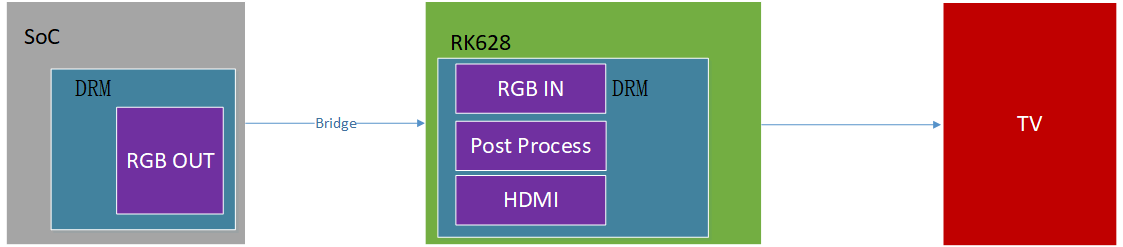
Original technical figure: EN V2.3, p37.
5.4.6.1 HDMI output configuration
Add the boolean property “rk628-hdmi-out” to the DTS RK628 node. Bind “&rgb” and RK628 using “remote-endpoint”:
&i2c2_rk628 {
   pinctrl-names = "default";

   pinctrl-0 = <&rk628_reset &refclk_pins>;
   assigned-clocks = <&pmucru CLK_WIFI>;
   assigned-clock-rates = <24000000>;
   clock-names = "soc_24M";
   clocks = <&pmucru CLK_WIFI>;

   rk628-rgb-in;
   rk628-hdmi-out;
   // mode-sync-pol = <0>;
   status = "okay";

   port {

      rgb_in_hdmi: endpoint {
         remote-endpoint = <&rgb_out_hdmi>;
      };
   };
};
&route_rgb {
   status = "disabled";

};

&rgb_in_vp2 {
   status = "okay";
};

&rgb {
   status = "okay";

   ports {
      port@1 {
         reg = <1>;


         rgb_out_hdmi: endpoint {
           remote-endpoint = <&rgb_in_hdmi>;
         };
      };
   };
};
HDMITX resolution and polarity follow standard resolutions, so no panel parameters are configured. For RGB/BT1120 input, set mode-sync-pol according to the actual hsync-active and vsync-active values. Because there is only one property, hsync-active and vsync-active must be equal. The default polarity is 1 (positive). Try this property if the image is corrupted.
The HDMITX path requires clocks with a common source, otherwise display errors may occur. See Core driver configuration → 24 MHz working clock.
5.4.6.2 Output-signal adjustment
See Core driver configuration → Output-signal adjustment → HDMI TX signal adjustment.
5.4.6.3 Audio configuration
&i2s0 {
   rockchip,playback-only;

   status = "oaky";
};

/ {
   rk628_sound: rk628-sound {
      compatible = "simple-audio-card";
      simple-audio-card,format = "i2s";
      simple-audio-card,mclk-fs = <128>;
      simple-audio-card,name = "rockchip,hdmi-rk628";
      status = "oaky";
      simple-audio-card,cpu {
         sound-dai = <&i2s0>;
      };
      simple-audio-card,codec {
         sound-dai = <&i2c2_rk628>;
      };

   };
}
5.5 Combinations currently supported by DTS
5.5.1 RGB → DSI conversion
Reference DTS:
arch/arm64/boot/dts/rockchip/rk3568-evb-rk628-ddr4-v10.dtsi
arch/arm64/boot/dts/rockchip/rk3568-evb-rk628-rgb2dsi-ddr4-v10.dts
These DTS files extend rk3568-evb.dtsi with RK628 RGB-to-MIPI-DSI support. Compare the code alongside Input module configuration and Output module configuration to understand the differences.
For SoC RGB output with specific timing, see Input module configuration → RGB input.
5.5.2 RGB → LVDS conversion
Reference DTS:
arch/arm64/boot/dts/rockchip/rk3568-evb-rk628-ddr4-v10.dtsi
arch/arm64/boot/dts/rockchip/rk3568-evb-rk628-rgb2lvds-ddr4-v10.dts
arch/arm64/boot/dts/rockchip/rk3568-evb-rk628-rgb2lvds-dual-ddr4-v10.dts
The source describes these DTS files as adding RK628 RGB-to-MIPI-DSI support to rk3568-evb.dtsi, although this section concerns LVDS. rk3568-evb-rk628-rgb2lvds-ddr4-v10.dts outputs single-channel LVDS; rk3568-evb-rk628-rgb2lvds-dual-ddr4-v10.dts outputs dual-channel LVDS. Compare their code with the input/output module descriptions.
For SoC RGB output with specific timing, see Input module configuration → RGB input.
5.5.3 RGB → GVI conversion
Reference DTS:
arch/arm64/boot/dts/rockchip/rk3568-evb-rk628-ddr4-v10.dtsi
arch/arm64/boot/dts/rockchip/rk3568-evb-rk628-rgb2gvi-ddr4-v10.dts
These DTS files extend rk3568-evb.dtsi with RK628 RGB-to-GVI conversion. Compare the code with the input/output module descriptions.
For SoC RGB output with specific timing, see Input module configuration → RGB input.
5.5.4 RGB → HDMI conversion
Reference DTS:
arch/arm64/boot/dts/rockchip/rk3568-evb-rk628-ddr4-v10.dtsi
arch/arm64/boot/dts/rockchip/rk3568-evb-rk628-rgb2hdmi-ddr4-v10.dts
These DTS files extend rk3568-evb.dtsi with RK628 RGB-to-HDMI conversion. Compare the code with the input/output module descriptions.
HDMITX detects the resolutions supported by the panel and selects a target resolution, so the SoC RGB-output timing is not configured in DTS.
5.5.5 HDMI → DSI conversion
Reference DTS:
arch/arm64/boot/dts/rockchip/rk3568-evb-rk628-ddr4-v10.dtsi
arch/arm64/boot/dts/rockchip/rk3568-evb-rk628-hdmi2dsi-ddr4-v10.dts

arch/arm64/boot/dts/rockchip/rk3568-evb-rk628-hdmi2dsi-dual-ddr4-v10.dts
These DTS files extend rk3568-evb.dtsi with RK628 HDMI-to-DSI conversion in direct-SoC mode. rk3568-evb-rk628-hdmi2dsi-ddr4-v10.dts outputs single MIPI DSI; rk3568-evb-rk628-hdmi2dsi-dual-ddr4-v10.dts outputs dual MIPI DSI. Compare the code with the input/output module descriptions.
For SoC output with specified timing, the source says RGB but refers to Input module configuration → HDMI input; verify this terminology.
5.5.6 HDMI → LVDS conversion
Reference DTS:
arch/arm64/boot/dts/rockchip/rk3568-evb-rk628-ddr4-v10.dtsi
arch/arm64/boot/dts/rockchip/rk3568-evb-rk628-hdmi2lvds-ddr4-v10.dts

arch/arm64/boot/dts/rockchip/rk3568-evb-rk628-hdmi2lvds-dual-ddr4-v10.dts
These DTS files extend rk3568-evb.dtsi with RK628 HDMI-to-LVDS conversion in direct-SoC mode. rk3568-evb-rk628-hdmi2lvds-ddr4-v10.dts outputs single-channel LVDS; rk3568-evb-rk628-hdmi2lvds-dual-ddr4-v10.dts outputs dual-channel LVDS. Compare the code with the input/output module descriptions.
For SoC output with specified timing, the source says RGB but refers to Input module configuration → HDMI input; verify this terminology.
5.5.7 HDMI → GVI conversion
Reference DTS:
arch/arm64/boot/dts/rockchip/rk3568-evb-rk628-ddr4-v10.dtsi
arch/arm64/boot/dts/rockchip/rk3568-evb-rk628-hdmi2gvi-ddr4-v10.dts
These DTS files extend rk3568-evb.dtsi with RK628 HDMI-to-GVI conversion in direct-SoC mode. Compare the code with the input/output module descriptions.
For SoC output with specified timing, the source says RGB but refers to Input module configuration → HDMI input; verify this terminology.
5.6 Basic debugging commands
5.6.1 Register-debug nodes
Under /sys/kernel/debug/regmap:
rk3568_t:/ # ls /sys/kernel/debug/regmap/
0-001c        2-0050-dsi1 2-0050-hdmirx 4-0050-gpio0
0-0020        2-0050-efuse 4-0050-adapter 4-0050-gpio1

0-0020-rk817-codec 2-0050-gpio0 4-0050-combrxphy 4-0050-gpio2
2-0050-adapter 2-0050-gpio1 4-0050-combtxphy 4-0050-gpio3
2-0050-combrxphy 2-0050-gpio2 4-0050-cru 4-0050-grf
2-0050-combtxphy 2-0050-gpio3 4-0050-csi 4-0050-gvi
2-0050-cru    2-0050-grf 4-0050-dsi0  4-0050-hdmi
2-0050-csi    2-0050-gvi 4-0050-dsi1  4-0050-hdmirx
2-0050-dsi0   2-0050-hdmi 4-0050-efuse ......
Or under /sys/kernel/debug/rk628/x-xxxx/registers:
rk3568_t:/ # ls /sys/kernel/debug/rk628/2-0050/registers/
adapter combrxphy combtxphy cru csi dsi0 dsi1 efuse gpio0 gpio1 gpio2
gpio3 grf gvi hdmi hdmirx
Here 2 is the I2C bus number and 0050 is the RK628 slave address.
1. Read registers, using GRF as the example:
Under /sys/kernel/debug/regmap:
rk3568_t:/ # cat /sys/kernel/debug/regmap/2-0050-grf/registers
000: 06000088
004: ffffffff

008: 00000000
00c: 00000000
010: 00000001
014: 00000000
018: 00050000
01c: 002c0898
020: 00c00840
......

rk3568_t:/ # cat /sys/kernel/debug/regmap/2-0050-grf/registers | grep 200:
200: 20230321
Or under /sys/kernel/debug/rk628/x-xxxx/registers:
rk3568_t:/ # cat /sys/kernel/debug/rk628/2-0050/registers/grf
rk628_grf:


0x0000: 06000298 ffffffff 00000000 00000001
0x0010: 00000001 00000000 000404b6 002804ba
0x0020: 0046047e 000a079e 00140794 0046047e
0x0030: 00140794 00000004 00000000 00000000
0x0040: 04380004 80000000 00000000 00000000
0x0050: 80000000 00000000 10000000 00000000
0x0060: 000002ea 01f0ea00 00000000 01f00000
0x0070: 0000155c 00005602 00000000 00000000
0x0080: 00006000 00000000 00000000 00000000
......

rk3568_t:/ # cat /sys/kernel/debug/rk628/2-0050/registers/grf | grep 0200:

0x0200: 20230321 00000000 00000000 00000000
2. Write registers, using GRF as the example:
Under /sys/kernel/debug/regmap:
rk3568_t:/ # echo 0x010 0x02000200 > /sys/kernel/debug/regmap/2-0050-
grf/registers
Or under /sys/kernel/debug/rk628/x-xxxx/registers:
rk3568_t:/ # echo 0x010 0x02000200 > /sys/kernel/debug/rk628/2-0050/registers/grf
5.6.2 Self-test commands
If the output is abnormal, use the following command to determine whether the problem is on the RK628 input or output side. This is available only on RK628F/H.
# Enable horizontal color bar
rk3568_t:/ # echo 1 > /sys/kernel/debug/rk628/2-0050/scaler_color_bar


# Enable vertical color bar
rk3568_t:/ # echo 2 > /sys/kernel/debug/rk628/2-0050/scaler_color_bar

# Disable color bar
rk3568_t:/ # echo 0 > /sys/kernel/debug/rk628/2-0050/scaler_color_bar
If the scaler colorbar displays correctly, investigate the host output, RK628 input and RK628 Process configuration. Otherwise check RK628 output first, then use each interface colorbar below to test its controller, PHY and panel path. If these module colorbars work but scaler color still does not display, continue investigating RK628 input.
The following commands test the output controller, its PHY and the panel path:
1. HDMITX colorbar
# Enable normal color bar
rk3568_t:/ # echo 1 > /sys/kernel/debug/rk628/2-0050/hdmitx_color_bar


# Enable special color bar
rk3568_t:/ # echo 2 > /sys/kernel/debug/rk628/2-0050/hdmitx_color_bar

# Enable black color bar
rk3568_t:/ # echo 3 > /sys/kernel/debug/rk628/2-0050/hdmitx_color_bar

# Disable color bar
rk3568_t:/ # echo 0 > /sys/kernel/debug/rk628/2-0050/hdmitx_color_bar
2. DSI colorbar
# Enable dsi color bar
rk3568_t:/ # echo 1 > /sys/kernel/debug/rk628/2-0050/dsi_color_bar


# Disable dsi color bar
rk3568_t:/ # echo 0 > /sys/kernel/debug/rk628/2-0050/dsi_color_bar
3. GVI colorbar
# Enable color bar
rk3568_t:/ # echo 1 > /sys/kernel/debug/rk628/2-0050/gvi_color_bar


# Disable color bar
rk3568_t:/ # echo 0 > /sys/kernel/debug/rk628/2-0050/gvi_color_bar
5.6.3 RGB IN debugging (RK628F/H only)
On RK628F/H, the following command reports the resolution actually received by RGB IN, helping determine whether RGB RX is operating correctly:
rk3568_t:/ # cat /sys/kernel/debug/rk628/2-0050/rgb_resolution
1080x1920 pclk:131967000
5.7 Common display problems
5.7.1 No regmap node
Check for RK628 errors in logs like the following that prevent successful probe:
rk3568_t:/ # dmesg | grep rk628
[  0.294331] rk628 2-0050: the driver version is 0.1.0 of RK628-F/B/G

[  0.294426] rk628 2-0050: failed to request enable GPIO: -16
5.7.2 I2C communication error
These logs indicate that RK628 I2C errors prevent its modules from registering. Check the RK628 power-up sequence, 24 MHz reference clock (see Common requirements) and the relevant pin IOMUX.
[ 0.960609] rk628 1-0050: failed to access register: -6
5.7.3 DSI/GVI has content but corrupted display
Try changing the blanking polarities in DTS src-timing. This applies to both DSI and GVI.
For example:
--- a/arch/arm64/boot/dts/rockchip/rk3568-evb-rk628-rgb2dsi-ddr4-v10.dts
+++ b/arch/arm64/boot/dts/rockchip/rk3568-evb-rk628-rgb2dsi-ddr4-v10.dts
@@ -347,8 +347,8 @@ src-timing {

                       vfront-porch = <15>;
                       hsync-len = <2>;
                       vsync-len = <2>;
-                      hsync-active = <0>;
-                      vsync-active = <0>;
+                      hsync-active = <1>;
+                      vsync-active = <1>;
                       de-active = <0>;
                       pixelclk-active = <0>;
5.7.4 No DSI display after increasing clock-frequency
Increasing the refresh rate normally requires increasing clock-frequency, for example:
--- a/arch/arm64/boot/dts/rockchip/rk3568-evb-rk628-rgb2dsi-ddr4-v10.dts
+++ b/arch/arm64/boot/dts/rockchip/rk3568-evb-rk628-rgb2dsi-ddr4-v10.dts
@@ -338,7 +338,7 @@ rk628-panel {


           display-timings {
                 src-timing {
-                      clock-frequency = <132000000>;
+                      clock-frequency = <148500000>;
                       hactive = <1080>;
                       vactive = <1920>;
                       hback-porch = <30>;
@@ -354,7 +354,7 @@ src-timing {
                 };

                 dst-timing {

-                      clock-frequency = <132000000>;
+                      clock-frequency = <148500000>;
                       hactive = <1080>;
                       vactive = <1920>;
                       hback-porch = <30>;
A higher CLK may cause flicker or no image. If this occurs, try adjusting the lane rate as follows:
--- a/arch/arm64/boot/dts/rockchip/rk3568-evb-rk628-rgb2dsi-ddr4-v10.dts
+++ b/arch/arm64/boot/dts/rockchip/rk3568-evb-rk628-rgb2dsi-ddr4-v10.dts
@@ -57,6 +57,7 @@ &i2c2_rk628 {


           rk628-rgb-in;
           rk628-dsi-out {
+                rockchip,lane-mbps = <1000>;
                 //rockchip,dual-channel;
                 dsi,eotp;
                 dsi,video-mode;
5.7.5 Display offset
For example, if HDMI input produces an offset image downstream, adjust panel blanking according to the offset direction in the DTS: hfront-porch/hback-porch/hsync-len and vfront-porch/vback-porch/vsync-len in src-timing/dst-timing. Ensure that output clock-frequency equals the HDMI input, for example 148500000 on both sides.
--- a/arch/arm64/boot/dts/rockchip/rk3568-evb-rk628-hdmi2dsi-ddr4-v10.dts
+++ b/arch/arm64/boot/dts/rockchip/rk3568-evb-rk628-hdmi2dsi-ddr4-v10.dts
@@ -314,7 +314,7 @@ src-timing {

                 hfront-porch = <60>;
                 vback-porch = <10>;
                 vfront-porch = <10>;
-                hsync-len = <20>;
+                hsync-len = <40>;
                 vsync-len = <10>;
                 hsync-active = <1>;
                 vsync-active = <1>;
5.7.6 Operating RK628 GPIOs
Call the GPIO interface at the required location, including rk628_pinctrl.h and rk628_gpio.h. The interface covers IOMUX, direction and level. The following sets I2S_D2_M0 to GPIO mode and drives it high:
#include "rk628_pinctrl.h"
#include "rk628_gpio.h"


rk628_misc_gpio_direction_output(rk628, GPIO0_A6, 1);
To restore the original function, call:
rk628_misc_pinctrl_set_mux(rk628, GPIO0_A6, I2SM0D2);
6. Media
6.1 Driver overview
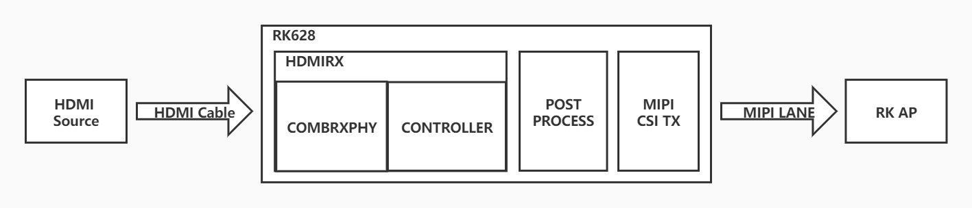
Original technical figure: EN V2.3, p46.
Media is the driver code for the RK628 HDMI IN path. It uses RK628 as a camera-like device to implement the functions shown above.
6.1.1 RK628F/H improvements over RK628D
The media driver mainly connects HDMI2CSI, HDMI2DSI or HDMI2BT1120 to a host SoC. Compared with RK628D, the principal RK628F/H improvements in this area are:
主要改进点
Module
Supports HDMI2.0 and RGB 4K60 input.
HDMIRX supports additional frequency points.
Supports DVI mode, with faster and more stable locking.
解决了不同图像格式输入,格式转换下采样引入的色偏问题
增加一路  MIPI-CSI,双 MIPI-CSI 支持 4K60 输出
MIPI-CSI
CSC adds a matrix for more flexible image color-space conversion.
6.1.2 Driver directory structure
RK628 media driver code differs by kernel version. Before kernel-5.10, use the rk628_for-all patch package; for kernel-5.10, use kernel_5.10_rk628_media_patch.
For kernels earlier than kernel-5.10, the directory structure is:
drivers/media/i2c/rk628
├── Makefile

├── rk628_bt1120_v4l2.c
├── rk628.c
├── rk628_combrxphy.c
├── rk628_combrxphy.h
├── rk628_combtxphy.c
├── rk628_combtxphy.h
├── rk628_cru.c
├── rk628_cru.h
├── rk628_csi.c
├── rk628_csi.h
├── rk628_csi_v4l2.c
├── rk628_dsi.c

├── rk628_dsi.h
├── rk628_gpio.h
├── rk628_grf.h
├── rk628.h
├── rk628_hdmirx.c
├── rk628_hdmirx.h
├── rk628_mipi_dphy.c
├── rk628_mipi_dphy.h
├── rk628_pinctrl.c
├── rk628_pinctrl.h
├── rk628_post_process.c
├── rk628_post_process.h

└── rk628_v4l2_controls.h
For kernel-5.10, the driver directory is:
drivers/media/i2c/rk628
├── Makefile

├── rk628_bt1120_v4l2.c
├── rk628.c
├── rk628_combrxphy.c
├── rk628_combrxphy.h
├── rk628_combtxphy.c
├── rk628_combtxphy.h
├── rk628_cru.c
├── rk628_cru.h
├── rk628_csi.c
├── rk628_csi.h
├── rk628_csi_v4l2.c
├── rk628_dsi.c
├── rk628_dsi.h

├── rk628.h
├── rk628_hdmirx.c
├── rk628_hdmirx.h
├── rk628_mipi_dphy.c
├── rk628_mipi_dphy.h
├── rk628_post_process.c
└── rk628_post_process.h
The main driver files and their intended use cases are:
rk628_csi.c: HDMI2CSI for CameraHal1 and third-party SoCs.
rk628_csi_v4l2.c: HDMI2CSI / HDMI2DSI for V4L2-based platforms such as CameraHal3 and TV input.
rk628_bt1120_v4l2.c: HDMI2BT1120 for V4L2-based platforms such as CameraHal3.
6.1.3 Driver porting
See Driver Porting → HDMI IN path (drivers/media/i2c/rk628).
6.2 HDMI IN video framework
The HDMI IN video implementation models RK628 as a MIPI SoC camera device. The camera or TV framework receives video for display in an APK. HDMI IN hotplug and automatic resolution adaptation are added for HDMI input use cases.
Android9/10/11 uses cameraHAL3. See Rockchip_Developer_Guide_HDMI_IN_Based_On_CameraHal3_CN.pdf under RKDocs/common/camera/hdmi-in in the SDK.
Android12/13 uses cameraHAL3/TVinput. See the following document under RKDocs/common/camera/hdmi-in in the SDK:
Rockchip_Developer_Guide_Android12+_HDMI_IN_Bridge_CN
6.2.1 HDMI IN APK workflow
The general APK workflow is shown below:
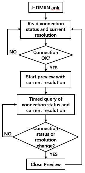
Original technical figure: EN V2.3, p49.
For kernel-4.19 or kernel-4.4 (Android 9/10/11), rkCamera2 can open the preview directly.
For kernel-5.10 (Android 12/13), distinguish the camera and TV frameworks. See:
Rockchip_Developer_Guide_Android12+_HDMI_IN_Bridge_CN
6.2.2 RK628 driver architecture
Three driver areas need particular attention: initialization, hotplug interrupt handling and resolution-change interrupt handling. Reference flowcharts follow:
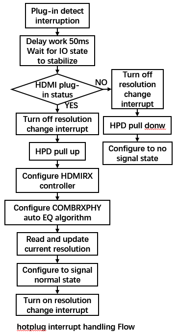
Original technical figure: EN V2.3, p51.
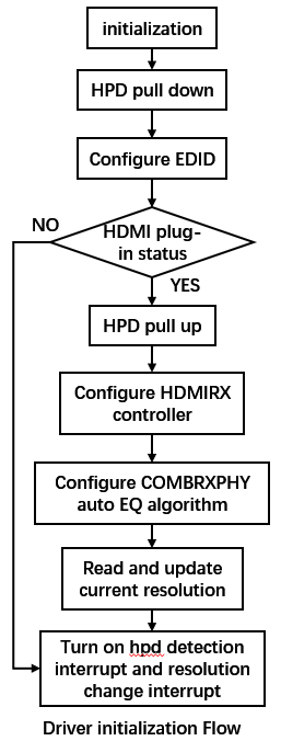
Original technical figure: EN V2.3, p50.
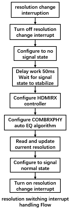
Original technical figure: EN V2.3, p52.
6.3 DTS configuration
6.3.1 RK628 node configuration
&i2c5 {
   status = "okay";


   rk628_csi: rk628_csi@50 {
      reg = <0x50>;
      compatible = "rockchip,rk628-csi-v4l2";
      status = "okay";
      power-domains = <&power RK3588_PD_VI>;
      pinctrl-names = "default";
      pinctrl-0 = <&rk628_pin>;
      interrupt-parent = <&gpio2>;
      interrupts = <RK_PC4 IRQ_TYPE_LEVEL_HIGH>;
      enable-gpios = <&gpio1 RK_PA0 GPIO_ACTIVE_HIGH>;
      reset-gpios = <&gpio4 RK_PC6 GPIO_ACTIVE_HIGH>;
      plugin-det-gpios = <&gpio1 RK_PA1 GPIO_ACTIVE_LOW>;

      continues-clk = <1>;

      rockchip,camera-module-index = <0>;
      rockchip,camera-module-facing = "back";
      rockchip,camera-module-name = "HDMI-MIPI";
      rockchip,camera-module-lens-name = "RK628-CSI";

      multi-dev-info {
         dev-idx-l = <0>;
         dev-idx-r = <1>;
         combine-idx = <0>;
         pixel-offset = <0>;

         dev-num = <2>;
      };

      port {
         hdmiin_out0: endpoint {
           remote-endpoint = <&hdmi_mipi0_in>;
           data-lanes = <1 2 3 4>;
         };
      };
   };
};
reg: I2C address. The typical RK628 7-bit address is 0x50. With multiple RK628 devices, its GPIO can change the address; see SoC–RK628 I2C Communication.
compatible:
compatible = “rockchip,rk628-csi” selects rk628_csi.c; compatible = “rockchip,rk628-csi-v4l2” selects rk628_csi_v4l2.c; compatible = “rockchip,rk628-bt1120-v4l2” selects rk628_bt1120_v4l2.c.
interrupt-parent/interrupts: GPIO pin connected to the RK628 interrupt.
enable-gpios: RK628 power-control GPIO; omit if power is always on.
reset-gpios: RK628 reset-control GPIO.
hpd-output-inverted: invert HPD output. Enable this if the hardware circuit inverts the HPD level.
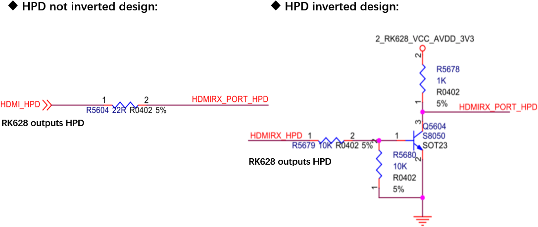
Original technical figure: EN V2.3, p54.
plugin-det-gpios: HDMI insertion-detection GPIO. Check whether the circuit inverts the level and configure the active level correctly.
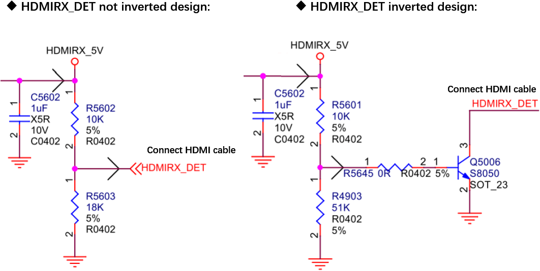
Original technical figure: EN V2.3, p54.
power-gpios: GPIO controlling the Rockchip host MIPI RX power domain; omit if always powered.
hdcp-enable: enable HDCP.
continues-clk: select continuous or non-continuous MIPI CSI output clock.
multi-dev-info: required for dual-MIPI 4K60 (RK628F/H only). The source lists RK3588/RK3562/RK3576 and kernel versions 5.10 or later.
6.3.2 Image reception paths
Develop RK628 as a camera-like converter with a V4L2 driver, just as for a camera sensor. Configure its data path as for a MIPI SoC sensor. Three common combinations are:
RK628 → HDMI2CSI → SoC
RK628 → HDMI2DSI → SoC
RK628 → HDMI2BT1120 → SoC
6.3.3 HDMI2CSI path
6.3.3.1 RK628D
RK3288 + CSI_V4L2 example: rk628 + isp1 path configuration.
&rk628_csi {
   status = "okay";
   /*

   * If the hpd output level is inverted on the circuit,
   * the following configuration needs to be enabled.
   */
   /* hpd-output-inverted; */
   plugin-det-gpios = <&gpio0 13 GPIO_ACTIVE_HIGH>;
   power-gpios = <&gpio0 17 GPIO_ACTIVE_HIGH>;
   rockchip,camera-module-index = <0>;
   rockchip,camera-module-facing = "back";
   rockchip,camera-module-name = "RK628-CSI";

   rockchip,camera-module-lens-name = "NC";

   port {
      hdmiin_out0: endpoint {
         remote-endpoint = <&mipi_in>;
         data-lanes = <1 2 3 4>;
      };
   };
};

&mipi_phy_rx0 {
   status = "okay";


   ports {
      #address-cells = <1>;
      #size-cells = <0>;

      port@0 {
         reg = <0>;
         #address-cells = <1>;
         #size-cells = <0>;

         mipi_in: endpoint@1 {
            reg = <1>;
            remote-endpoint = <&hdmiin_out0>;

            data-lanes = <1 2 3 4>;
         };
      };

      port@1 {
         reg = <1>;
         #address-cells = <1>;
         #size-cells = <0>;

         dphy_rx_out: endpoint@0 {
            reg = <0>;
            remote-endpoint = <&isp_mipi_in>;

         };
      };
   };
};

&rkisp1 {
   status = "okay";
   port {
      #address-cells = <1>;
      #size-cells = <0>;

      isp_mipi_in: endpoint@0 {
         reg = <0>;

         remote-endpoint = <&dphy_rx_out>;
      };
   };
};

&isp_mmu {

   status = "okay";
};
RK3568 + CSI_V4L2 example: rk628 + isp2 path configuration:
&i2c2 {
   status = "okay";

   pinctrl-names = "default";
   pinctrl-0 = <&i2c2m1_xfer>;

   rk628_csi: rk628_csi@32 {
      compatible = "rockchip,rk628-csi-v4l2";
      reg = <0x50>;
      interrupt-parent = <&gpio4>;
      interrupts = <16 IRQ_TYPE_LEVEL_LOW>;
      pinctrl-names = "default";
      pinctrl-0 = <&rk628_irq>;
      reset-gpios = <&gpio4 RK_PD2 GPIO_ACTIVE_LOW>;
      plugin-det-gpios = <&gpio0 RK_PD6 GPIO_ACTIVE_LOW>;
      rockchip,camera-module-index = <0>;

      rockchip,camera-module-facing = "back";
      rockchip,camera-module-name = "RK628-CSI";
      rockchip,camera-module-lens-name = "NC";
      port {
         rk628_out: endpoint {
           remote-endpoint = <&mipi_in>;
           data-lanes = <1 2 3 4>;
         };
      };
   };
};


&csi2_dphy_hw {
   status = "okay";
};

&csi2_dphy0 {
   status = "okay";

   ports {
      #address-cells = <1>;
      #size-cells = <0>;
      port@0 {
         reg = <0>;
         #address-cells = <1>;

         #size-cells = <0>;

         mipi_in: endpoint@0 {
           reg = <0>;
           remote-endpoint = <&rk628_out>;
           data-lanes = <1 2 3 4>;
         };
      };
      port@1 {
         reg = <1>;

         #address-cells = <1>;
         #size-cells = <0>;

         csidphy0_out: endpoint@0 {
           reg = <0>;
           remote-endpoint = <&isp0_in>;
         };
      };
   };
};

&rkisp {

   status = "okay";
};

&rkisp_mmu {
   status = "okay";
};

&rkisp_vir0 {
   status = "okay";

   port {
      #address-cells = <1>;
      #size-cells = <0>;


      isp0_in: endpoint@0 {
         reg = <0>;
         remote-endpoint = <&csidphy0_out>;
      };
   };
};
RK3568 rk628 + vicap path configuration:
&i2c2 {
   status = "okay";
   pinctrl-names = "default";

   pinctrl-0 = <&i2c2m1_xfer>;

   rk628_csi: rk628_csi@32 {
      compatible = "rockchip,rk628-csi-v4l2";
      reg = <0x50>;
      //clocks = <&ext_cam_clk>;
      //clock-names = "xvclk";

      interrupt-parent = <&gpio4>;
      interrupts = <16 IRQ_TYPE_LEVEL_LOW>;
      pinctrl-names = "default";
      pinctrl-0 = <&rk628_irq>;

      //power-gpios = <&gpio0 RK_PD5 GPIO_ACTIVE_HIGH>;
      reset-gpios = <&gpio4 RK_PD2 GPIO_ACTIVE_LOW>;
      plugin-det-gpios = <&gpio0 RK_PD6 GPIO_ACTIVE_LOW>;
      rockchip,camera-module-index = <0>;
      rockchip,camera-module-facing = "back";

      rockchip,camera-module-name = "RK628-CSI";
      rockchip,camera-module-lens-name = "NC";
      port {
         rk628_out: endpoint {
            remote-endpoint = <&mipi_in>;
            data-lanes = <1 2 3 4>;
         };
      };
   };
};

&csi2_dphy_hw {

   status = "okay";
};

&csi2_dphy0 {
   status = "okay";

   ports {
      #address-cells = <1>;
      #size-cells = <0>;
      port@0 {
         reg = <0>;
         #address-cells = <1>;
         #size-cells = <0>;


         mipi_in: endpoint@0 {
            reg = <0>;
            remote-endpoint = <&rk628_out>;
            data-lanes = <1 2 3 4>;
         };
      };
      port@1 {
         reg = <1>;
         #address-cells = <1>;
         #size-cells = <0>;


         csidphy0_out: endpoint@0 {
            reg = <0>;
            remote-endpoint = <&mipi_csi2_input>;
            data-lanes = <1 2 3 4>;
         };
      };
   };
};

&mipi_csi2 {
   status = "okay";

   ports {

      #address-cells = <1>;
      #size-cells = <0>;
      port@0 {
         reg = <0>;
         #address-cells = <1>;

         #size-cells = <0>;

         mipi_csi2_input: endpoint@1 {
           reg = <1>;
           remote-endpoint = <&csidphy0_out>;
           data-lanes = <1 2 3 4>;
         };
      };

      port@1 {
         reg = <1>;
         #address-cells = <1>;

         #size-cells = <0>;

         mipi_csi2_output: endpoint@0 {
           reg = <0>;
           remote-endpoint = <&cif_mipi_in>;
           data-lanes = <1 2 3 4>;
         };
      };
   };
};

&rkcif {
   status = "okay";

};

&rkcif_mipi_lvds {
   status = "okay";

   port {
      cif_mipi_in: endpoint {
         remote-endpoint = <&mipi_csi2_output>;
         data-lanes = <1 2 3 4>;
      };
   };
};


&rkcif_mmu {
   status = "okay";
};
6.3.3.2 RK628F/H
RK628F/H host-SoC DTS configuration is essentially the same as RK628D; refer to that example.
RK628F/H supports dual MIPI. This paragraph states that only RK3588/RK3562 hosts are supported. The following RK3588 dual-MIPI example connects RK628F/H CSI0/CSI1 to RK3588 CSI0/CSI1 through vicap.
&csi2_dphy0 {
   status = "okay";
   ports {
      #address-cells = <1>;

      #size-cells = <0>;
      port@0 {
         reg = <0>;
         #address-cells = <1>;
         #size-cells = <0>;

         hdmi_mipi2_in: endpoint@1 {
            reg = <1>;
            remote-endpoint = <&hdmiin_out1>;
            data-lanes = <1 2 3 4>;
         };
      };

      port@1 {
         reg = <1>;
         #address-cells = <1>;
         #size-cells = <0>;

         csidphy0_out: endpoint@0 {
            reg = <0>;
            remote-endpoint = <&mipi2_csi2_input>;
         };
      };
   };
};


&csi2_dphy0_hw {
   status = "okay";
};

&csi2_dphy1_hw {
   status = "okay";
};

&i2c3 {
   status = "okay";
   clock-frequency = <400000>;


   rk628_csi: rk628_csi@50 {
      reg = <0x50>;
      compatible = "rockchip,rk628-csi-v4l2";
      status = "okay";
      power-domains = <&power RK3588_PD_VI>;
      pinctrl-names = "default";
      pinctrl-0 = <&rk628_pin>;
      interrupt-parent = <&gpio1>;
      interrupts = <RK_PB2 IRQ_TYPE_LEVEL_HIGH>;
      enable-gpios = <&gpio1 RK_PA7 GPIO_ACTIVE_HIGH>;
      reset-gpios = <&gpio1 RK_PB1 GPIO_ACTIVE_HIGH>;
      plugin-det-gpios = <&gpio2 RK_PB6 GPIO_ACTIVE_LOW>;
      continues-clk = <1>;


      rockchip,camera-module-index = <0>;
      rockchip,camera-module-facing = "back";
      rockchip,camera-module-name = "HDMI-MIPI2";
      rockchip,camera-module-lens-name = "RK628-CSI";


      multi-dev-info {
         dev-idx-l = <2>;
         dev-idx-r = <4>;
         combine-idx = <2>;
         pixel-offset = <0>;
         dev-num = <2>;
      };

      port {
         hdmiin_out1: endpoint {
            remote-endpoint = <&hdmi_mipi2_in>;
            data-lanes = <1 2 3 4>;

         };
      };
   };
};

&mipi_dcphy0 {
   status = "okay";
};

&mipi_dcphy1 {
   status = "okay";
};


&mipi2_csi2 {
   status = "okay";

   ports {
      #address-cells = <1>;
      #size-cells = <0>;

      port@0 {
         reg = <0>;
         #address-cells = <1>;
         #size-cells = <0>;


         mipi2_csi2_input: endpoint@1 {
            reg = <1>;
            remote-endpoint = <&csidphy0_out>;
         };
      };

      port@1 {
         reg = <1>;
         #address-cells = <1>;
         #size-cells = <0>;

         mipi2_csi2_output: endpoint@0 {
            reg = <0>;

            remote-endpoint = <&cif_mipi_in2>;
         };
      };
   };
};


&rkcif {
   status = "okay";
};

&rkcif_mipi_lvds2 {
   status = "okay";

   port {
      cif_mipi_in2: endpoint {
         remote-endpoint = <&mipi2_csi2_output>;
      };
   };

};

&rkcif_mmu {
   status = "okay";
};
6.3.4 HDMI2DSI conversion
6.3.4.1 RK628D
For RK628D HDMI-to-MIPI-CSI, color-space conversion or up/downsampling can introduce small color-detail deviations. HDMI-to-MIPI-DSI is an alternative: the host receives RGB888 directly and the application converts it with rgb2yuv. Note:
Maximum resolution: 1080P60.
APs listed as supporting MIPI DSI reception: RK1109, RK1126, RK3566, RK3568, RK3588, RK3562 and RK3576 (source spellings retained).
Earlier APs such as RK3288, RK3326, RK3368 and RK3399 do not support MIPI DSI reception.
CSI and DSI share compatible code and are distinguished by DTS compatible:
CSI: compatible = “rockchip,rk628-csi-v4l2”;
DSI: compatible = “rockchip,rk628-dsi-v4l2”;
RK3568 example:
&i2c2 {
   status = "okay";
   pinctrl-names = "default";

   pinctrl-0 = <&i2c2m1_xfer>;

   rk628_csi: rk628_csi@32 {
      compatible = "rockchip,rk628-dsi-v4l2";
      reg = <0x50>;

      interrupt-parent = <&gpio4>;
      interrupts = <16 IRQ_TYPE_LEVEL_LOW>;
      pinctrl-names = "default";
      pinctrl-0 = <&rk628_irq>;
      //power-gpios = <&gpio0 RK_PD5 GPIO_ACTIVE_HIGH>;
      reset-gpios = <&gpio4 RK_PD2 GPIO_ACTIVE_LOW>;

      plugin-det-gpios = <&gpio0 RK_PD6 GPIO_ACTIVE_LOW>;
      rockchip,camera-module-index = <0>;
      rockchip,camera-module-facing = "back";
      rockchip,camera-module-name = "RK628-CSI";
      rockchip,camera-module-lens-name = "NC";
      port {
         rk628_out: endpoint {
            remote-endpoint = <&hdmi2mipi_in>;
            data-lanes = <1 2 3 4>;
         };
      };
   };

};

&mipi_csi2 {
   status = "okay";

   ports {
      #address-cells = <1>;
      #size-cells = <0>;

      port@0 {
         reg = <0>;
         #address-cells = <1>;
         #size-cells = <0>;


         mipi_csi2_input: endpoint@1 {
            reg = <1>;
            remote-endpoint = <&csidphy_out>;
            data-lanes = <1 2 3 4>;
         };
      };

      port@1 {
         reg = <1>;
         #address-cells = <1>;
         #size-cells = <0>;


         mipi_csi2_output: endpoint@0 {
            reg = <0>;
            remote-endpoint = <&cif_mipi_in>;
            data-lanes = <1 2 3 4>;
         };
      };
   };
};

&rkcif {
   status = "okay";
};


&rkcif_mipi_lvds {
   status = "okay";
   port {
      cif_mipi_in: endpoint {

         remote-endpoint = <&mipi_csi2_output>;
         data-lanes = <1 2 3 4>;
      };
   };
};

&rkcif_mmu {
   status = "okay";
};

&csi2_dphy_hw {
   status = "okay";

};

&csi2_dphy0 {
   status = "okay";

   ports {
      #address-cells = <1>;
      #size-cells = <0>;
      port@0 {
         reg = <0>;
         #address-cells = <1>;
         #size-cells = <0>;


         hdmi2mipi_in: endpoint@0 {
           reg = <1>;
           remote-endpoint = <&rk628_out>;
           data-lanes = <1 2 3 4>;
         };
      };
      port@1 {
         reg = <1>;
         #address-cells = <1>;
         #size-cells = <0>;

         csidphy_out: endpoint@0 {

           reg = <0>;
           remote-endpoint = <&mipi_csi2_input>;
         };
      };
   };
};
For an RK3568 host with older code, CIF needs the following commit to receive RGB888:
RK3588 kernel-5.10 drivers support RGB888 by default.
From e925e385a41a857e8e50020b5df9a2d41b166d83 Mon Sep 17 00:00:00 2001
From: Zefa Chen <zefa.chen@rock-chips.com>
Date: Thu, 02 Sep 2021 15:07:13 +0800

Subject: [PATCH] media: rockchip: cif fix errors in rgb24 data format
Signed-off-by: Zefa Chen <zefa.chen@rock-chips.com>
Change-Id: I0766997860f06dc25e604c2ea8425049a987fdc5

---

diff --git a/drivers/media/platform/rockchip/cif/capture.c b/drivers/media/platform/rockchip/cif/capture.c
index 6c0aa7d..36bd2c9 100644
--- a/drivers/media/platform/rockchip/cif/capture.c
+++ b/drivers/media/platform/rockchip/cif/capture.c
@@ -1785,13 +1785,11 @@
     * needs aligned with :ALIGN(bits_per_pixel * width * 2, 8), to optimize
reading and
     * writing of ddr, aliged with 256
     */

-   if (fmt->fmt_type == CIF_FMT_TYPE_RAW && stream->is_compact) {
+   if (fmt->fmt_type == CIF_FMT_TYPE_RAW && stream->is_compact &&
+      fmt->csi_fmt_val != CSI_WRDDR_TYPE_RGB888) {
       channel->virtual_width = ALIGN(channel->width * fmt->raw_bpp / 8, 256);
    } else {
-      if (fmt->fmt_type == CIF_FMT_TYPE_RAW && fmt->csi_fmt_val !=
CSI_WRDDR_TYPE_RAW8)
-         channel->virtual_width = ALIGN(channel->width * 2, 8);
-      else
-         channel->virtual_width = ALIGN(channel->width * fmt->bpp[0] / 8, 8);
+      channel->virtual_width = ALIGN(channel->width * fmt->bpp[0] / 8, 8);
    }


    if (channel->fmt_val == CSI_WRDDR_TYPE_RGB888)
@@ -3240,7 +3238,8 @@

       if (fmt->fmt_type == CIF_FMT_TYPE_RAW && stream->is_compact &&
          (dev->active_sensor->mbus.type == V4L2_MBUS_CSI2 ||
-         dev->active_sensor->mbus.type == V4L2_MBUS_CCP2)) {
+         dev->active_sensor->mbus.type == V4L2_MBUS_CCP2) &&
+         fmt->csi_fmt_val != CSI_WRDDR_TYPE_RGB888) {
          bpl = ALIGN(width * fmt->raw_bpp / 8, 256);
       } else {
          bpp = rkcif_align_bits_per_pixel(stream, fmt, i);
@@ -4659,13 +4658,11 @@

     * needs aligned with :ALIGN(bits_per_pixel * width * 2, 8), to optimize
reading and
     * writing of ddr, aliged with 256
     */
-   if (fmt->fmt_type == CIF_FMT_TYPE_RAW && stream->is_compact) {
+   if (fmt->fmt_type == CIF_FMT_TYPE_RAW && stream->is_compact &&
+      fmt->csi_fmt_val != CSI_WRDDR_TYPE_RGB888) {
       *crop_vwidth = ALIGN(raw_width * fmt->raw_bpp / 8, 256);
    } else {
-      if (fmt->fmt_type == CIF_FMT_TYPE_RAW)
-         *crop_vwidth = ALIGN(raw_width * 2, 8);
-      else
-         *crop_vwidth = ALIGN(raw_width * fmt->bpp[0] / 8, 8);

+      *crop_vwidth = ALIGN(raw_width * fmt->bpp[0] / 8, 8);
    }
if (channel->fmt_val == CSI_WRDDR_TYPE_RGB888)
rk628-dsi outputs command mode by default; CIF reception must also use command mode. Modify as follows:
diff --git a/drivers/media/platform/rockchip/cif/capture.c b/drivers/media/platform/rockchip/cif/capture.c

index 36bd2c99c707..fc4181daed2c 100644
--- a/drivers/media/platform/rockchip/cif/capture.c
+++ b/drivers/media/platform/rockchip/cif/capture.c
@@ -1753,7 +1753,7 @@ static int rkcif_csi_channel_init(struct rkcif_stream
*stream,

      channel->fmt_val = stream->cif_fmt_out->csi_fmt_val;

-     channel->cmd_mode_en = 0; /* default use DSI Video Mode */
+     channel->cmd_mode_en = 1; /* default use DSI Video Mode */

      if (stream->crop_enable) {
           channel->crop_en = 1;
Connecting to the camera framework
RK356X hosts can use only the camera framework, which cannot send RGB directly to display. Add the rgb2yuv library.
Add the following rgb2yuv library to CameraHal. For Android 11-R9 SDK code, apply rk356x_HAL3_support_rgb2yuv_patch.rar directly.
For R10 or R11, first make the following change under hardware/rockchip/camera, then apply the patch above.
diff --git a/psl/rkisp2/RKISP2GraphConfig.cpp b/psl/rkisp2/RKISP2GraphConfig.cpp
index 2a5fa5a..3d2409c 100755
--- a/psl/rkisp2/RKISP2GraphConfig.cpp

+++ b/psl/rkisp2/RKISP2GraphConfig.cpp
@@ -76,6 +76,7 @@ const string MEDIACTL_POSTVIEWNAME = "postview";

 const string MEDIACTL_STATNAME = "rkisp1-statistics";
 const string MEDIACTL_VIDEONAME_CIF = "stream_cif_dvp_id0";
+const string MEDIACTL_VIDEONAME_CIF_MIPI_ID0 = "stream_cif_mipi_id0";

 RKISP2GraphConfig::RKISP2GraphConfig() :
      mManager(nullptr),
@@ -2620,6 +2621,13 @@ status_t RKISP2GraphConfig::getImguMediaCtlConfig(int32_t
cameraId,
            addLinkParams("rkisp-isp-subdev", 2, "rkisp_mainpath", 0, 1,

MEDIA_LNK_FL_ENABLED, mediaCtlConfig);
            addLinkParams("rkisp-isp-subdev", 2, "rkisp_selfpath", 0, 1,
MEDIA_LNK_FL_ENABLED, mediaCtlConfig);
         }
+     } else if(mipName2.find("mipi") != std::string::npos) {
+        addLinkParams(mipName, mipSrcPad, mipName2, csiSinkPad, 1,
MEDIA_LNK_FL_ENABLED, mediaCtlConfig);
+        addLinkParams(mipName2, 1, "stream_cif_mipi_id0", 0, 1,
MEDIA_LNK_FL_ENABLED, mediaCtlConfig);
+        addLinkParams(mipName2, 2, "stream_cif_mipi_id1", 0, 1,
MEDIA_LNK_FL_ENABLED, mediaCtlConfig);
+        addLinkParams(mipName2, 3, "stream_cif_mipi_id2", 0, 1,

MEDIA_LNK_FL_ENABLED, mediaCtlConfig);
+        addLinkParams(mipName2, 4, "stream_cif_mipi_id3", 0, 1,
MEDIA_LNK_FL_ENABLED, mediaCtlConfig);
+        mSensorLinkedToCIF = true;
      } else {
         addLinkParams(mipName, mipSrcPad, csiName, csiSinkPad, 1,
MEDIA_LNK_FL_ENABLED, mediaCtlConfig);
         addLinkParams(csiName, csiSrcPad, IspName, ispSinkPad, 1,
MEDIA_LNK_FL_ENABLED, mediaCtlConfig);
@@ -2628,6 +2636,12 @@ status_t RKISP2GraphConfig::getImguMediaCtlConfig(int32_t
cameraId,
         addLinkParams(csiName, 5, "rkisp_rawwr3", 0, 1,

MEDIA_LNK_FL_ENABLED, mediaCtlConfig);
      }
   }
+  if(mSensorLinkedToCIF){
+     addImguVideoNode(IMGU_NODE_VIDEO, MEDIACTL_VIDEONAME_CIF_MIPI_ID0,
mediaCtlConfig);
+     addFormatParams(MEDIACTL_VIDEONAME_CIF_MIPI_ID0, mCurSensorFormat.width,
mCurSensorFormat.height,
+           0, V4L2_PIX_FMT_NV12, 0, 0, mediaCtlConfig);
+     return OK;
+  }
   // isp input pad format and selection config
   addFormatParams(IspName, ispInWidth, ispInHeight, ispSinkPad, ispInFormat,

0, 0, mediaCtlConfig);
   addSelectionParams(IspName, ispInWidth, ispInHeight, 0, 0,
V4L2_SEL_TGT_CROP, ispSinkPad, mediaCtlConfig);
This patch applies only to RK3568+ANDROID11.
Connecting to the TV framework
With RK3588 or RK3576, HDMI-to-DSI can use the TV framework to send RGB888 directly to display, without the rgb2yuv library. See APK adaptation below.
6.3.4.2 RK628F/H
RK628F/H resolves the RK628D color deviations introduced by conversion/downsampling with different input formats.
For demanding image-quality applications, RK628F/H can output RGB888 over DSI. Hosts such as RK3588 can receive RGB888 and display it directly through TV without color conversion, preserving image quality as described in the source. RK628F/H has two MIPI-DSI interfaces and also supports dual-MIPI connection to RK3588.
RK3588 + RK628F/H dual-MIPI example:
Only compatible needs to be changed to the DSI value.
......
&i2c3 {

   status = "okay";
   clock-frequency = <400000>;
   rk628_csi: rk628_csi@50 {
      reg = <0x50>;

      compatible = "rockchip,rk628-dsi-v4l2";
      status = "okay";
      power-domains = <&power RK3588_PD_VI>;
      pinctrl-names = "default";
      pinctrl-0 = <&rk628_pin>;
      interrupt-parent = <&gpio1>;
      interrupts = <RK_PB2 IRQ_TYPE_LEVEL_HIGH>;
      enable-gpios = <&gpio1 RK_PA7 GPIO_ACTIVE_HIGH>;
      reset-gpios = <&gpio1 RK_PB1 GPIO_ACTIVE_HIGH>;
      plugin-det-gpios = <&gpio2 RK_PB6 GPIO_ACTIVE_LOW>;

      rockchip,camera-module-index = <0>;

      rockchip,camera-module-facing = "back";
      rockchip,camera-module-name = "HDMI-MIPI2";
      rockchip,camera-module-lens-name = "RK628-CSI";

      multi-dev-info {
         dev-idx-l = <2>;
         dev-idx-r = <4>;
         combine-idx = <2>;
         pixel-offset = <0>;
         dev-num = <2>;
      };

      port {

         hdmiin_out1: endpoint {
           remote-endpoint = <&hdmi_mipi2_in>;
           data-lanes = <1 2 3 4>;
         };
      };
   };
};
......
6.3.5 HDMI2BT1120 conversion
HDMI2BT1120 path configuration is essentially the same for RK628D and RK628F/H, so it is not repeated.
RK3568 + BT1120_V4L2 example:
&i2c4 {
pinctrl-names = "default";
pinctrl-0 = <&i2c4m1_xfer>;
clock-frequency = <400000>;
status = "okay";
rk628_bt1120: rk628_bt1120@50 {
compatible = "rockchip,rk628-bt1120-v4l2";
reg = <0x50>;
status = "disabled";
pinctrl-names = "default";
pinctrl-0 = <&cif_dvp_clk &cif_dvp_bus16 &cif_dvp_bus8>;
interrupt-parent = <&gpio2>;
interrupts = <15 IRQ_TYPE_LEVEL_HIGH>;
enable-gpios = <&gpio2 RK_PC0 GPIO_ACTIVE_HIGH>;
reset-gpios = <&gpio2 RK_PB0 GPIO_ACTIVE_LOW>;
plugin-det-gpios = <&gpio1 RK_PA2 GPIO_ACTIVE_LOW>;
rockchip,camera-module-index = <0>;
rockchip,camera-module-facing = "back";
rockchip,camera-module-name = "RK628-BT1120";
rockchip,camera-module-lens-name = "NC";
dual-edge = <1>;
port {
lt8619c_out: endpoint {
remote-endpoint = <&cif_para_in>;
bus-width = <16>;
pclk-sample = <1>;
};
};
};
};
&rkcif_dvp {
status = "okay";
port {
/* Parallel bus endpoint */
cif_para_in: endpoint {
remote-endpoint = <<8619c_out>;
};
};
};
&rkcif {
status = "okay";
};
&rkcif_mmu {
status = "okay";
};
6.4 Enabling HDCP
RK628 HDMIRX supports HDCP1.4. HDCP is disabled by default; enable it when needed:
1. Enable HDCP in the RK628 DTS node.
           reset-gpios = <&gpio7 RK_PB4 GPIO_ACTIVE_LOW>;
           plugin-det-gpios = <&gpio0 13 GPIO_ACTIVE_HIGH>;

           power-gpios = <&gpio0 17 GPIO_ACTIVE_HIGH>;
+          hdcp-enable = <1>;
2. Program the HDCP RX key.
HDCP keys must be purchased from the HDCP association; Rockchip does not supply them. The original says keys distinguish TX and “RK Key” and that “RK Key” is required. This spelling conflicts with the RX heading and is retained as a source issue, not silently corrected.
After receiving the key source file, use KeyConverter to split keys and convert them to .skf programming files; follow the tool instructions.
Program the .skf file with RKDevInfoWriteTool, which encrypts the key. See the tool instructions.
6.5 Enabling the scaler
Some hosts cannot receive MIPI 4K although RK628 HDMI IN accepts 4K input. To output CSI at 1080P regardless of input resolution, add this DTS configuration:
           reset-gpios = <&gpio7 RK_PB4 GPIO_ACTIVE_LOW>;
           plugin-det-gpios = <&gpio0 13 GPIO_ACTIVE_HIGH>;
           power-gpios = <&gpio0 17 GPIO_ACTIVE_HIGH>;

+          scaler-en = <1>;
6.6 Two-lane CSI
CSI defaults to 4 lanes:
csi->csi_lanes_in_use = USE_4_LANES;
For 2 lanes, set csi->csi_lanes_in_use to 2.
6.7 Continuous and non-continuous MIPI
To enable continuous MIPI mode, configure DTS:
continues-clk = <1>;
6.8 Dual-MIPI configuration (RK628F/H only)
MIPI DPHY rate limits RK628F/H to 4K30 on one MIPI interface. RK628F/H has two MIPI-CSI interfaces. With hosts such as RK3588/RK3562 that have multiple CSI inputs, split 4K60 video into left and right halves, transmit them over two 4-lane MIPI-CSI links, and combine them into 4K60 at the host.
The source states that hosts such as RK3588 combine the images directly in the VI driver without additional latency or load. This is a source claim, not an ArmSoM measurement.
6.8.1 Dual-MIPI split mode
RK628F/H can internally split the HDMIRX image into left/right halves and send each through one CSI interface:
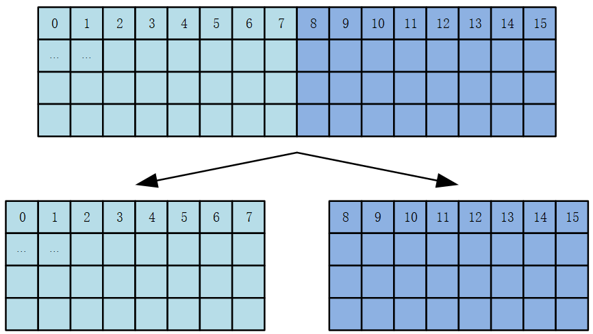
Original technical figure: EN V2.3, p72.
This allows hosts with multiple MIPI interfaces, such as RK3588, to receive 4K60 through dual MIPI. The functional flow is shown below.
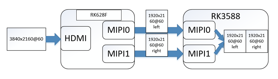
Original technical figure: EN V2.3, p72.
6.8.2 Dual-MIPI configuration
The following configures RK628F/H dual MIPI with RK3588 for 4K60 HDMI-IN.
For dual-MIPI debugging with Rockchip SoCs, see Rockchip_RK3588_HDMI_To_CSI_Dual_Mipi_Developer_Guide under RKDocs/common/camera/HAL3 in the SDK.
6.8.2.1 RK628F/H configuration
The RK628F/H driver supports dual MIPI and defaults to two CSI interfaces for 4K60 HDMI-IN. DTS multi-dev-info fields are:
dev-idx-l: MIPI interface index for the left image half.
dev-idx-r: MIPI interface index for the right image half.
combine-idx: index into which both image halves are combined; use this index for the DTS path.
pixel-offset: pixel offset, default 0.
dev-num: number of MIPI devices to combine.
Example: RK628F/H CSI0/1 connected to RK3588 CSI0/1 RX:
&i2c3 {
   status = "okay";

   clock-frequency = <400000>;

   rk628_csi: rk628_csi@50 {
      reg = <0x50>;
      compatible = "rockchip,rk628-csi-v4l2";
      status = "okay";
      power-domains = <&power RK3588_PD_VI>;
      pinctrl-names = "default";
      pinctrl-0 = <&rk628_pin>;
      interrupt-parent = <&gpio1>;
      interrupts = <RK_PB2 IRQ_TYPE_LEVEL_HIGH>;
      enable-gpios = <&gpio1 RK_PA7 GPIO_ACTIVE_HIGH>;
      reset-gpios = <&gpio1 RK_PB1 GPIO_ACTIVE_HIGH>;

      plugin-det-gpios = <&gpio2 RK_PB6 GPIO_ACTIVE_LOW>;
      continues-clk = <1>;

      rockchip,camera-module-index = <0>;
      rockchip,camera-module-facing = "back";
      rockchip,camera-module-name = "HDMI-MIPI2";
      rockchip,camera-module-lens-name = "RK628-CSI";

      multi-dev-info {
         dev-idx-l = <2>;
         dev-idx-r = <4>;
         combine-idx = <2>;

         pixel-offset = <0>;
         dev-num = <2>;
      };

      port {
         hdmiin_out1: endpoint {
           remote-endpoint = <&hdmi_mipi2_in>;
           data-lanes = <1 2 3 4>;
         };
      };
   };
};
6.8.2.2 Host SoC driver requirements
The source lists RK3588/RK3562/RK3576 as Rockchip hosts supporting dual MIPI, with the kernel-5.10 generation and later code required. Host code must be sufficiently recent; update the Android 12/13 SDK as recommended by the source. Updating only the kernel-
5.10 RK628 driver may cause compilation failure if the rest of the SDK is too old to support dual MIPI. Update the SDK or contact Rockchip engineers through Redmine.
6.9 Reception capabilities by chip
Maximum reception capability differs with each platform’s ISP/VICAP performance. Refer to the table:
| SoC platform | Receiver controller | Maximum supported resolution |
|---|---|---|
| RK3288/RK3326/RK3368 | isp | 1920x1080P60 |
| RK3399 | isp | 3840x2160P30 (isp overclocking required) |
| RK3566/RK3568 | vicap/isp | 3840x2160P30 (maximum 1080P60 when connected to ISP) |
| RK3588/RK3562/RK3576 | vicap | 3840x2160P60 (dual MIPI) |
6.9.1 ISP overclock configuration
Configure RK3399 PLL_NPLL to 650M:
--- a/arch/arm64/boot/dts/rockchip/rk3399-vop-clk-set.dtsi
+++ b/arch/arm64/boot/dts/rockchip/rk3399-vop-clk-set.dtsi
@@ -148,7 +148,7 @@

                  <50000000>, <100000000>,
                  <75000000>, <75000000>,
                  <816000000>, <816000000>,
-                 <600000000>, <200000000>,
+                 <650000000>, <200000000>,
                  <800000000>, <150000000>,
                  <75000000>, <37500000>,
                  <300000000>, <100000000>,
Change RK3399’s maximum supported ISP frequency to 650M:
--- a/drivers/media/platform/rockchip/isp1/dev.c
+++ b/drivers/media/platform/rockchip/isp1/dev.c
@@ -757,7 +757,7 @@ static const unsigned int rk3368_isp_clk_rate[] = {


 /* isp clock adjustment table (MHz) */
 static const unsigned int rk3399_isp_clk_rate[] = {
-     300, 400, 600
+     300, 400, 650
 };

 static struct isp_irqs_data rk1808_isp_irqs[] = {
For intermittent RK3288 ISP errors, a higher ISP frequency may also be tried. Usually only the highest frequency needs to remain. This change is for diagnosis only.
--- a/drivers/media/platform/rockchip/isp1/dev.c
+++ b/drivers/media/platform/rockchip/isp1/dev.c
@@ -849,7 +849,7 @@ static const unsigned int rk1808_isp_clk_rate[] = {


 /* isp clock adjustment table (MHz) */
static const unsigned int rk3288_isp_clk_rate[] = {
-     150, 384, 500, 594
+     594
 };
Configure the ISP frequency in the converter driver.
#define RK628_CSI_PIXEL_RATE_HIGH 600000000
...


static int rk628_csi_set_fmt(struct v4l2_subdev *sd,
           struct v4l2_subdev_pad_config *cfg,
           struct v4l2_subdev_format *format)
{
...
      if ((mode->width == 3840) && (mode->height == 2160)) {
           v4l2_dbg(1, debug, sd,
                 "%s res wxh:%dx%d, link freq:%llu, pixrate:%u\n",
                 __func__, mode->width, mode->height,
                 link_freq_menu_items[1], RK628_CSI_PIXEL_RATE_HIGH);
           __v4l2_ctrl_s_ctrl(csi->link_freq, 1);
           __v4l2_ctrl_s_ctrl_int64(csi->pixel_rate,

                 RK628_CSI_PIXEL_RATE_HIGH);
      }
...
}
The ISP driver adds 25% margin to the configured frequency, so set an appropriate RK628_CSI_PIXEL_RATE_HIGH in the driver.
drivers/media/platform/rockchip/isp1/dev.c

static int __isp_pipeline_s_isp_clk(struct rkisp1_pipeline *p)

{
...
      ctrl = v4l2_ctrl_find(sd->ctrl_handler, V4L2_CID_PIXEL_RATE);
      if (!ctrl) {
           v4l2_warn(sd, "No pixel rate control in subdev\n");
           return -EPIPE;
      }

      /* calculate data rate */
      data_rate = v4l2_ctrl_g_ctrl_int64(ctrl) *
              dev->isp_sdev.in_fmt.bus_width;
      data_rate >>= 3;
      do_div(data_rate, 1000 * 1000);


      /* increase 25% margin */
      data_rate += data_rate >> 2;
...
}
6.9.2 Configuring ISP to use CMA memory
On some platforms, system load can cause insufficient bandwidth during HDMI IN reception, resulting in dropped frames or MIPI errors. Example error log:
[ 228.999567] rkisp1: MIPI mis error: 0x00800000
[ 228.999925] rkisp1: CIF_ISP_PIC_SIZE_ERROR (0x00000001)
[ 228.999976] rkisp1: CIF_ISP_PIC_SIZE_ERROR (0x00000001)rkisp1:

CIF_ISP_PIC_SIZE_ERROR (0x00000001)
[ 229.000081] rkisp1: CIF_ISP_PIC_SIZE_ERROR (0x00000001)rkisp1:
CIF_ISP_PIC_SIZE_ERROR (0x00000001)
[ 229.000187] rkisp1: CIF_ISP_PIC_SIZE_ERROR (0x00000001)rkisp1:
CIF_ISP_PIC_SIZE_ERROR (0x00000001)
[ 229.000294] rkisp1: CIF_ISP_PIC_SIZE_ERROR (0x00000001)rkisp1:
CIF_ISP_PIC_SIZE_ERROR (0x00000001)
Increase DDR frequency. If that does not help, reserve CMA memory for ISP to improve the situation:
Reserve 128MB of CMA in rockchip_defconfig.
CONFIG_CMA=y
CONFIG_CMA_SIZE_MBYTES=128
Disable ISP IOMMU in DTS and use CMA memory.
&isp_mmu {
      status = "disabled";

};
6.10 EDID configuration
RK628 supports EDID configuration. The current source driver advertises common resolutions including:
3840x2160P60, 3840x2160P30, 1920x1080P60, 1920x1080P30, 1280x720P60, 720x576P50 and 720x480P60. To change the supported resolutions, edit EDID directly in the driver:
static u8 rk628f_edid_init_data[] = {
   0x00, 0xFF, 0xFF, 0xFF, 0xFF, 0xFF, 0xFF, 0x00,
   0x24, 0xD0, 0x8F, 0x62, 0x01, 0x00, 0x00, 0x00,

   0x2D, 0x21, 0x01, 0x03, 0x80, 0x78, 0x44, 0x78,
   0x0A, 0xCF, 0x74, 0xA3, 0x57, 0x4C, 0xB0, 0x23,
   0x09, 0x48, 0x4C, 0x21, 0x08, 0x00, 0x61, 0x40,
   0x01, 0x01, 0x81, 0x00, 0x95, 0x00, 0xA9, 0xC0,
   0x01, 0x01, 0x01, 0x01, 0x01, 0x01, 0x08, 0xE8,
   0x00, 0x30, 0xF2, 0x70, 0x5A, 0x80, 0xB0, 0x58,
   0x8A, 0x00, 0xC4, 0x8E, 0x21, 0x00, 0x00, 0x1E,
   0x02, 0x3A, 0x80, 0x18, 0x71, 0x38, 0x2D, 0x40,
   0x58, 0x2C, 0x45, 0x00, 0xB9, 0xA8, 0x42, 0x00,
   0x00, 0x1E, 0x00, 0x00, 0x00, 0xFC, 0x00, 0x49,
   0x46, 0x50, 0x20, 0x44, 0x69, 0x73, 0x70, 0x6C,

   0x61, 0x79, 0x0A, 0x20, 0x00, 0x00, 0x00, 0xFD,
   0x00, 0x3B, 0x46, 0x1F, 0x8C, 0x3C, 0x00, 0x0A,
   0x20, 0x20, 0x20, 0x20, 0x20, 0x20, 0x01, 0xA8,

   0x02, 0x03, 0x39, 0xF2, 0x4D, 0x01, 0x03, 0x12,
   0x13, 0x84, 0x22, 0x1F, 0x90, 0x5D, 0x5E, 0x5F,
   0x60, 0x61, 0x23, 0x09, 0x07, 0x07, 0x83, 0x01,
   0x00, 0x00, 0x6D, 0x03, 0x0C, 0x00, 0x10, 0x00,
   0x00, 0x44, 0x20, 0x00, 0x60, 0x03, 0x02, 0x01,
   0x67, 0xD8, 0x5D, 0xC4, 0x01, 0x78, 0xC0, 0x00,
   0xE3, 0x05, 0x03, 0x01, 0xE4, 0x0F, 0x00, 0x18,
   0x00, 0x02, 0x3A, 0x80, 0x18, 0x71, 0x38, 0x2D,

   0x40, 0x58, 0x2C, 0x45, 0x00, 0xB9, 0xA8, 0x42,
   0x00, 0x00, 0x1E, 0x08, 0xE8, 0x00, 0x30, 0xF2,
   0x70, 0x5A, 0x80, 0xB0, 0x58, 0x8A, 0x00, 0xC4,
   0x8E, 0x21, 0x00, 0x00, 0x1E, 0x00, 0x00, 0x00,
   0x00, 0x00, 0x00, 0x00, 0x00, 0x00, 0x00, 0x00,
   0x00, 0x00, 0x00, 0x00, 0x00, 0x00, 0x00, 0x00,
   0x00, 0x00, 0x00, 0x00, 0x00, 0x00, 0x00, 0x00,
   0x00, 0x00, 0x00, 0x00, 0x00, 0x00, 0x00, 0x93,
};
The source recommends this EDID editor (historical source link, not a verified current download): http://www.quantumdata.com/support/downloads/980/release_5_05/R_980mgr_5.05_Win32.msi
6.11 camera3_profiles.xml configuration
Camera-framework preview requires camera3_profiles.xml adaptation to register the camera device.
camera3_profiles.xml is located under the SDK directory for the corresponding chip:
hardware/rockchip/camera/etc/camera/camera3_profiles_rk3xxx.xml
Key configuration points follow. For details, refer to SoC Sensor configuration.
name: must match the driver name, including case.
moduleId: must match index in the driver’s DTS.

Original technical figure: EN V2.3, p78.
Editable transcription of fully visible screenshot text. Cropped edge characters are not reconstructed; fragments are not necessarily standalone executable examples.
</Profiles>
<Profiles cameraId="0" name="rk628-csi" moduleId="m00">
    <Supported_hardware>
        <hwType value="SUPPORTED_HW_RKISP1"/>
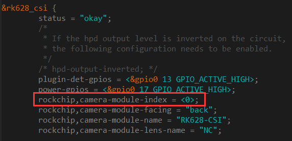
Original technical figure: EN V2.3, p78.
Editable transcription of fully visible screenshot text. Cropped edge characters are not reconstructed; fragments are not necessarily standalone executable examples.
&rk628_csi {
    status = "okay";
    /*
     * If the hpd output level is inverted on the circuit,
     * the following configuration needs to be enabled.
     */
    /* hpd-output-inverted; */
    plugin-det-gpios = <&gpio0 13 GPIO_ACTIVE_HIGH>;
    power-gpios = <&gpio0 17 GPIO_ACTIVE_HIGH>;
    rockchip,camera-module-index = <0>;
    rockchip,camera-module-facing = "back";
    rockchip,camera-module-name = "RK628-CSI";
    rockchip,camera-module-lens-name = "NC";
scaler.availableStreamConfigurations/scaler.availableMinFrameDurations/scaler.availableStallDurations: correctly specify supported resolutions and minimum frame intervals. Add corresponding entries whenever the driver adds a resolution.
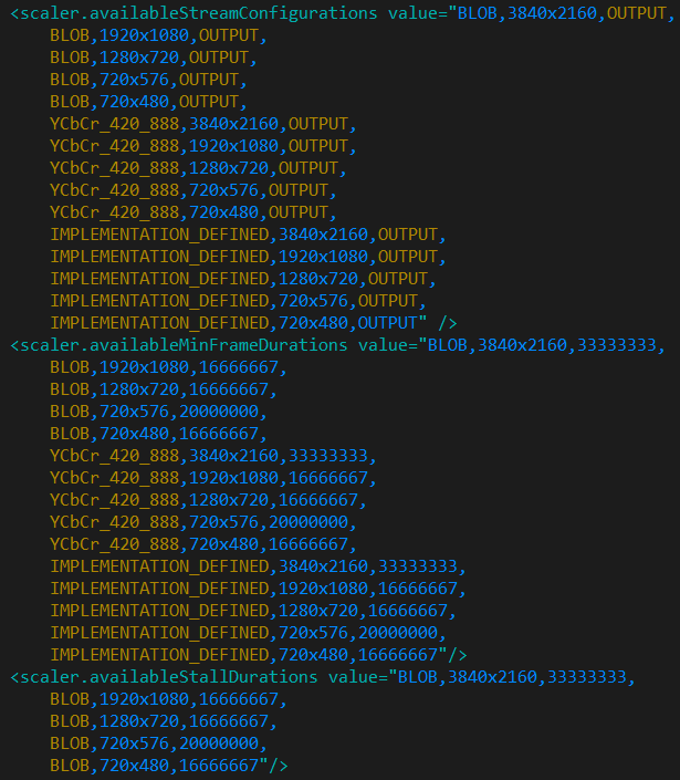
Original technical figure: EN V2.3, p79.
Editable transcription of fully visible screenshot text. Cropped edge characters are not reconstructed; fragments are not necessarily standalone executable examples.
<scaler.availableStreamConfigurations value="BLOB,3840x2160,OUTPUT,
    BLOB,1920x1080,OUTPUT,
    BLOB,1280x720,OUTPUT,
    BLOB,720x576,OUTPUT,
    BLOB,720x480,OUTPUT,
    YCbCr_420_888,3840x2160,OUTPUT,
    YCbCr_420_888,1920x1080,OUTPUT,
    YCbCr_420_888,1280x720,OUTPUT,
    YCbCr_420_888,720x576,OUTPUT,
    YCbCr_420_888,720x480,OUTPUT,
    IMPLEMENTATION_DEFINED,3840x2160,OUTPUT,
    IMPLEMENTATION_DEFINED,1920x1080,OUTPUT,
    IMPLEMENTATION_DEFINED,1280x720,OUTPUT,
    IMPLEMENTATION_DEFINED,720x576,OUTPUT,
    IMPLEMENTATION_DEFINED,720x480,OUTPUT" />
<scaler.availableMinFrameDurations value="BLOB,3840x2160,33333333,
    BLOB,1920x1080,16666667,
    BLOB,1280x720,16666667,
    BLOB,720x576,20000000,
    BLOB,720x480,16666667,
    YCbCr_420_888,3840x2160,33333333,
    YCbCr_420_888,1920x1080,16666667,
    YCbCr_420_888,1280x720,16666667,
    YCbCr_420_888,720x576,20000000,
    YCbCr_420_888,720x480,16666667,
    IMPLEMENTATION_DEFINED,3840x2160,33333333,
    IMPLEMENTATION_DEFINED,1920x1080,16666667,
    IMPLEMENTATION_DEFINED,1280x720,16666667,
    IMPLEMENTATION_DEFINED,720x576,20000000,
    IMPLEMENTATION_DEFINED,720x480,16666667"/>
<scaler.availableStallDurations value="BLOB,3840x2160,33333333,
    BLOB,1920x1080,16666667,
    BLOB,1280x720,16666667,
    BLOB,720x576,20000000,
    BLOB,720x480,16666667"/>
sensor.orientation: image rotation; supports 0, 90, 180 and 270.

Original technical figure: EN V2.3, p79.
Editable transcription of fully visible screenshot text. Cropped edge characters are not reconstructed; fragments are not necessarily standalone executable examples.
<sensor.maxAnalogSensitivity value="2400"/>
<sensor.orientation value="0"/>
<sensor.profileHueSatMapDimensions value="0,0,0"/>
6.12 HDMI IN APK adaptation
6.12.1 Android 9/10/11
Android 9/10/11 uses kernel-4.4/kernel-4.19 and the for-all patch package. Only cameraHAL3 is available.
6.12.1.1 Obtaining and building APK sources
APK sources are supplied in this SDK directory:
RKDocs/common/hdmi-in/apk/rkCamera2_based_on_CameraHal3_V1.3.tar.gz
Copy and extract the sources into:
packages/apps/
For RK3288, modify device/rockchip/rk3288/ as follows to build rkCamera2:
diff --git a/device.mk b/device.mk
index 6667b5c..96f08f1 100644

--- a/device.mk
+++ b/device.mk
@@ -17,7 +17,8 @@
 PRODUCT_PACKAGES += \
   memtrack.$(TARGET_BOARD_PLATFORM) \
   WallpaperPicker \
-  Launcher3
+  Launcher3 \
+  rkCamera2

 #$_rbox_$_modify_$_zhengyang: add displayd
 PRODUCT_PACKAGES += \
6.12.1.2 Adapting APK sources
The APK accesses the RK628 device node through ioctl to obtain connection status and resolution. The node can differ between isp1/isp2/vicap paths. Adapt APK sources to the actual node; see the debugging-command examples for finding it.
rkCamera2/jni/native.cpp
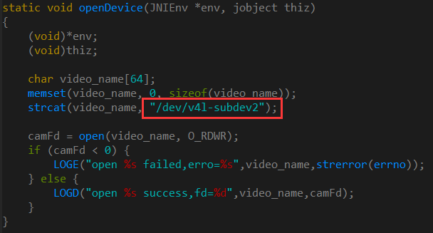
Original technical figure: EN V2.3, p81.
Editable transcription of fully visible screenshot text. Cropped edge characters are not reconstructed; fragments are not necessarily standalone executable examples.
static void openDevice(JNIEnv *env, jobject thiz)
{
    (void)*env;
    (void)thiz;

    char video_name[64];
    memset(video_name, 0, sizeof(video_name));
    strcat(video_name, "/dev/v4l-subdev2");

    camFd = open(video_name, O_RDWR);
    if (camFd < 0) {
        LOGE("open %s failed,erro=%s",video_name,strerror(errno));
    } else {
        LOGD("open %s success,fd=%d",video_name,camFd);
    }
}
Code to obtain connection status and resolution:
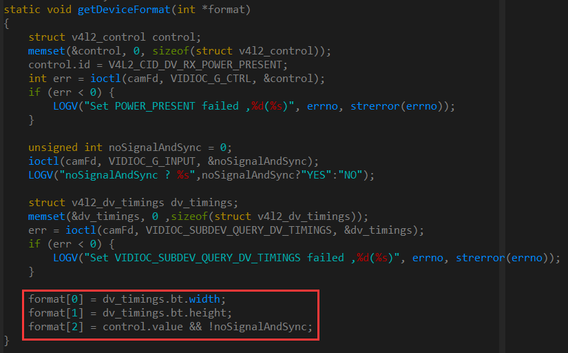
Original technical figure: EN V2.3, p81.
Editable transcription of fully visible screenshot text. Cropped edge characters are not reconstructed; fragments are not necessarily standalone executable examples.
static void getDeviceFormat(int *format)
{
    struct v4l2_control control;
    memset(&control, 0, sizeof(struct v4l2_control));
    control.id = V4L2_CID_DV_RX_POWER_PRESENT;
    int err = ioctl(camFd, VIDIOC_G_CTRL, &control);
    if (err < 0) {
        LOGV("Set POWER_PRESENT failed ,%d(%s)", errno, strerror(errno));
    }

    unsigned int noSignalAndSync = 0;
    ioctl(camFd, VIDIOC_G_INPUT, &noSignalAndSync);
    LOGV("noSignalAndSync ? %s",noSignalAndSync?"YES":"NO");

    struct v4l2_dv_timings dv_timings;
    memset(&dv_timings, 0 ,sizeof(struct v4l2_dv_timings));
    err = ioctl(camFd, VIDIOC_SUBDEV_QUERY_DV_TIMINGS, &dv_timings);
    if (err < 0) {
        LOGV("Set VIDIOC_SUBDEV_QUERY_DV_TIMINGS failed ,%d(%s)", errno, strerror(errno));
    }

    format[0] = dv_timings.bt.width;
    format[1] = dv_timings.bt.height;
    format[2] = control.value && !noSignalAndSync;
}
Because the APK accesses a device node, the source asks to check whether SELinux is disabled, using getenforce. Treat this as a source debugging instruction, not a production security recommendation:
Original technical figure: EN V2.3, p81.
Editable transcription of fully visible screenshot text. Cropped edge characters are not reconstructed; fragments are not necessarily standalone executable examples.
rk3288:/ # getenforce
Enforcing
rk3288:/ # setenforce 0
rk3288:/ #
rk3288:/ # getenforce
Permissive
6.12.1.3 Preparing for APK debugging
First complete driver debugging (see Driver Debugging). Then verify camera registration in CameraHal with the command below. If registration is incorrect, check camera3_profiles.xml as described in its configuration section.
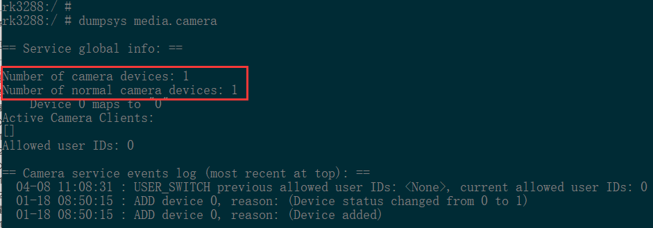
Original technical figure: EN V2.3, p82.
Editable transcription of fully visible screenshot text. Cropped edge characters are not reconstructed; fragments are not necessarily standalone executable examples.
rk3288:/ #
rk3288:/ # dumpsys media.camera

== Service global info: ==

Number of camera devices: 1
Number of normal camera devices: 1
    Device 0 maps to "0"
Active Camera Clients:
[]
Allowed user IDs: 0

== Camera service events log (most recent at top): ==
  04-08 11:08:31 : USER_SWITCH previous allowed user IDs: <None>, current allowed user IDs: 0
  01-18 08:50:15 : ADD device 0, reason: (Device status changed from 0 to 1)
  01-18 08:50:15 : ADD device 0, reason: (Device added)
6.12.2 Android 12+
Android 12/13 uses kernel-5.10 and its matching driver patch package. Applications use either camera or TV (also called TIF below). See Rockchip_Android12+_HDMI_TO_MIPI_Developer_Guide for debugging.
Android14 uses kernel-6.1, with the driver included in the SDK. The source recommends the TV framework.
6.12.2.1 APK sources
packages/apps/TV/partner_support/samples: TV source-data service, interacting through the framework with HAL and the preview APK. It runs as a hidden boot-time service, so its APK icon is hidden on the launcher.
hardware/rockchip/tv_input: TVHAL code, exchanging commands with the driver for stream on/off, hotplug and resolution-change events.
hardware/rockchip/camera: cameraHAL code implementing camera streaming, still capture and related functions.
vendor/rockchip/hardware/interfaces/hdmi: used by camera; listens for resolution changes and hotplug and communicates with the driver and APK.
packages/apps/rkCamera2: preview APK with two screens. Default MainActivity previews through TIF and interacts with the TV source service through framework. RockchipCamera2 previews through Camera, using standard Camera API to open the MIPI node’s cameraid. Its launcher icon is named HdmiIn. Customers commonly replace it with their own preview APK.
HDMI IN is disabled in the default SDK. Set the following property to enable it and build the relevant modules, including the APKs above:
vim device/rockchip/rk3588/BoardConfig.mk
BOARD_HDMI_IN_SUPPORT := true
For the camera framework, enable:
vim device/rockchip/rk3588/BoardConfig.mk
CAMERA_SUPPORT_HDMI := true
If only CAMERA_SUPPORT_HDMI is configured, without BOARD_HDMI_IN_SUPPORT, add rkCamera2 to the build and set persist.sys.hdmiinmode to 2 to preview with rkCamera2 through camera. For further details see:
Rockchip_Developer_Guide_HDMI_RX_CN
PRODUCT_PACKAGES += \
   rkCamera2
6.12.2.2 APK preview
The APK previews either the RK3588 HDMI RX path or the HDMI-to-MIPI-CSI path; select the appropriate one.
For TIF preview, select the MIPI-CSI2 path:
setprop vendor.tvinput.hdmiin.type 1
For camera preview, open RockchipCamera2 and ensure CAMERA_SUPPORT_HDMI is enabled.
setprop persist.sys.hdmiinmode 2
6.12.2.3 TIF versus camera preview
| TIF | Camera | |
|---|---|---|
| Advantages | Low latency | The application can obtain preview data for post-processing |
| Disadvantages | No screen rotation, split-screen or picture-in-picture; the application cannot obtain preview-buffer data; screencap screenshot commands are unsupported | Higher latency than TIF |
6.13 Common driver debugging methods
Debug the driver as for a SoC Sensor. For additional information, refer to the Redmine document:
https://redmine.rock-chips.com/documents/53
6.13.1 Obtaining debugging tools
media-ctl and v4l2-ctl are required. The source SDK automatically copies them into firmware during the build; their SDK directory is:
hardware/rockchip/camera/etc/tools/
For older SDK versions, obtain them from Redmine:
https://redmine.rock-chips.com/documents/104
Use adb push to copy media-ctl and v4l2-ctl to /vendor/bin/ on the device.
6.13.2 Debugging command examples
This example uses RK3288 + RK628 receiving 1920x1080P. Adapt it to the actual system. Enter the following commands in order; skipping earlier configuration can prevent operation.
Inspect link topology:
Run the command to inspect the media-node topology. Depending on the platform and connections, the node may be /dev/media0 or /dev/media1.
media-ctl -d /dev/media0 –p
In the RK628 excerpt, the device is /dev/v4l-subdev2 and detected HDMI IN resolution is 1920x1080.
...
- entity 8: m00_b_rk628-csi rk628-csi (1 pad, 1 link)
         type V4L2 subdev subtype Sensor

         device node name /dev/v4l-subdev2
      pad0: Source
           [fmt:UYVY2X8/1920x1080]
           -> "rockchip-mipi-dphy-rx":0 [ENABLED]
...
Configure links:
Links are connected by default after reset/startup. Opening and closing the HDMI IN APK disconnects them. Reconnect only if the topology lacks [ENABLED].
media-ctl -d /dev/media0 -l \
'"m00_b_rk628-csi rk628-csi":0->"rockchip-mipi-dphy-rx":0 [1]'

media-ctl -d /dev/media0 -l \
'"rockchip-mipi-dphy-rx":1->"rkisp1-isp-subdev":0 [1]'
media-ctl -d /dev/media0 -l '"rkisp1-input-params":0->"rkisp1-isp-subdev":1 [1]'
media-ctl -d /dev/media0 -l '"rkisp1-isp-subdev":2->"rkisp1_mainpath":0 [1]'
media-ctl -d /dev/media0 -l '"rkisp1-isp-subdev":2->"rkisp1_selfpath":0 [1]'
media-ctl -d /dev/media0 -l '"rkisp1-isp-subdev":3->"rkisp1-statistics":0 [1]'
Configure resolution:
media-ctl -d /dev/media0 \
--set-v4l2 '"rkisp1-isp-subdev":0[fmt:UYVY2X8/1920x1080]'
media-ctl -d /dev/media0 \

--set-v4l2 '"rkisp1-isp-subdev":0[crop:(0,0)/1920x1080]'
media-ctl -d /dev/media0 \
--set-v4l2 '"rkisp1-isp-subdev":2[fmt:UYVY2X8/1920x1080]'
media-ctl -d /dev/media0 \
--set-v4l2 '"rkisp1-isp-subdev":2[crop:(0,0)/1920x1080]'
Capture the image stream:
Inspect configuration results:
media-ctl -d /dev/media0 –p
Capture the image stream:
v4l2-ctl --verbose -d /dev/video0 --set-fmt-
video=width=1920,height=1080,pixelformat='NV12' --stream-mmap=4
Capture a YUV image file, retrieve it with adb pull and inspect it with a tool such as 7yuv:
v4l2-ctl -d /dev/video0 --set-fmt-video=width=1920,height=1080,pixelformat='NV12'
--stream-mmap=3 --stream-skip=4 --stream-to=/data/1920x1080p60_nv12.yuv --stream-
count=5 --stream-poll
If image data is received normally, frame rates are printed. Source log example:
VIDIOC_QUERYCAP: ok
VIDIOC_G_FMT: ok
VIDIOC_S_FMT: ok

Format Video Capture Multiplanar:
      Width/Height : 1920/1080
      Pixel Format : 'NV12'
      Field        : None
      Number of planes : 1
      Flags        :
      Colorspace   : Default
      Transfer Function : Default
      YCbCr Encoding : Default
      Quantization : Full Range
      Plane 0      :
        Bytes per Line : 1920
        Size Image : 3110400

VIDIOC_G_SELECTION: ok
VIDIOC_S_SELECTION: ok
VIDIOC_REQBUFS: ok
VIDIOC_QUERYBUF: ok
VIDIOC_QUERYBUF: ok
VIDIOC_QBUF: ok
VIDIOC_QUERYBUF: ok
VIDIOC_QBUF: ok
VIDIOC_QUERYBUF: ok
VIDIOC_QBUF: ok
VIDIOC_QUERYBUF: ok
VIDIOC_QBUF: ok

VIDIOC_STREAMON: ok
idx: 0 seq: 0 bytesused: 3110400 ts: 131.560377
idx: 1 seq: 1 bytesused: 3110400 ts: 131.577023 delta: 16.646 ms
idx: 2 seq: 2 bytesused: 3110400 ts: 131.593697 delta: 16.674 ms
idx: 3 seq: 3 bytesused: 3110400 ts: 131.610363 delta: 16.666 ms
idx: 0 seq: 4 bytesused: 3110400 ts: 131.627033 delta: 16.670 ms fps: 60.01
idx: 1 seq: 5 bytesused: 3110400 ts: 131.643721 delta: 16.688 ms fps: 59.99
idx: 2 seq: 6 bytesused: 3110400 ts: 131.660390 delta: 16.669 ms fps: 59.99
idx: 3 seq: 7 bytesused: 3110400 ts: 131.677058 delta: 16.668 ms fps: 59.99
6.13.3 Enabling logs
Enable RK628 logs with the following command, then collect the kernel log. The source spells the retrieval command demsg; verify the actual dmesg command on the target.
echo 1 > /sys/kernel/debug/rk628/x-0050/debug //x为挂载的i2c总线,50为对应的i2c地址
echo 2 > /sys/module/rk628_csi/parameters/debug
echo 2 > /sys/module/rk628_csi_v4l2/parameters/debug //内核为linux4.4或者4.19

dmesg -n 8
To capture power-on/boot logs, modify the code directly and rebuild/reflash the kernel components:
diff --git a/drivers/media/i2c/rk628_csi.c b/drivers/media/i2c/rk628_csi.c
index c763a9558169..bd7f3effb45a 100644
--- a/drivers/media/i2c/rk628_csi_v4l2.c

+++ b/drivers/media/i2c/rk628_csi_v4l2.c
@@ -34,7 +34,7 @@
 #include <video/videomode.h>
 #include "rk628_csi.h"

-static int debug;
+static int debug = 1;
 module_param(debug, int, 0644);
 MODULE_PARM_DESC(debug, "debug level (0-3)");

diff --git a/include/media/v4l2-common.h b/include/media/v4l2-common.h
index 1cc0c5ba16b3..e74f3a85f0b8 100644
--- a/include/media/v4l2-common.h

+++ b/include/media/v4l2-common.h
@@ -75,7 +75,7 @@
 #define v4l2_dbg(level, debug, dev, fmt, arg...)   \
      do {                                          \
           if (debug >= (level))                    \
-                v4l2_printk(KERN_DEBUG, dev, fmt , ## arg); \
+                v4l2_printk(KERN_INFO, dev, fmt , ## arg); \
      } while (0)
6.13.4 Register reads and writes
RK628 register debug nodes follow. In this example RK628 is on I2C3 at address 0x50:
console:/ # ls /sys/kernel/debug/rk628/3-0050/registers/
adapter combtxphy csi dsi0 gpio0 gpio2 grf hdmirxphy

combrxphy cru   csi1 dsi1 gpio1 gpio3 hdmirx
The register nodes support reads and writes.
Read registers:
console:/ # cat /sys/kernel/debug/rk628/3-0050/registers/cru
rk628_cru:


0xc0000: 00001031 00000441 00800000 00000007
0xc0010: 00007f00
0xc0020: 00001028 00000441 00f5c28f 00000007
0xc0030: 00007f00
0xc0040: 00005019 00000541 0099735e 00000007
0xc0050: 00007f00
0xc0060: 00000015
0xc0080: 00008989 00000003 00000007 00004b80
0xc0090: 03355460 000080d7 00008004 0000003b
0xc00a0: 00002c00 00000000 00000000 00000000
0xc00b0: 00285f58 00010008 00010008 00000103
0xc00c0: 00000300 00000703 0000000b 00000008

0xc00d0: 0001000a 00000b07
0xc0180: 00000000 00000000 00000000 00000000
0xc0190: 00000000 00000000
0xc0200: 00000000 00000000 00000000 00000000
0xc0210: 00000000
Write registers:
rk3288:/ # echo 0x000 0xffffffff > /sys/kernel/debug/rk628/3-0050/registers/grf
6.13.5 Reading HDMI-RX status
Read HDMI-RX information, including resolution, lock state, plug/unplug state and color format, with:
console:/ # cat /sys/kernel/debug/rk628/3-0050/hdmirx/status
status: plugin

Clk-Ch:Lock Ch0:Lock   Ch1:Lock    Ch2:Lock
Color Format: RGB
Timing: 1920x1080p60 (2200x1125)   hfp:88 hs:45 hbp:147 vfp:4
vs:5 vbp:36
Pixel Clk: 148500000
Mode: HDMI
Color Depth: 8 bit
Color Range: Limited
Color Space: RGB
6.13.6 Pattern output
RK628 supports scaler color-bar output. Commands:
echo 1 > /sys/kernel/debug/rk628/3-0050/scaler_color_bar

//pattern 模式选择

echo 2 > /sys/kernel/debug/rk628/3-0050/scaler_color_bar
6.14 Audio module
Audio can be configured as output or input depending on whether HDMIRX or HDMITX is used. With HDMIRX, received HDMI audio is unpacked and output through I2S. With HDMITX, RK628D I2S receives audio input, which is packetized and transmitted through HDMITX. Both configurations follow:
6.14.1 HDMIRX
HDMIRX normally initializes audio when the driver loads, requiring no additional configuration. When the HDMI transmitter plays audio, RK628 outputs it through I2S and must be the master. RK628 I2S can connect directly to an I2S-capable DAC or SoC. I2S format:
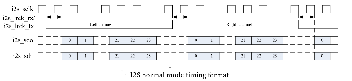
Original technical figure: EN V2.3, p86.
When connected to a SoC, RK628 I2S needs no extra configuration; use dummy_codec to create a sound card for the system:
rk628_dc: rk628-dc {
      compatible = "rockchip,dummy-codec";
      #sound-dai-cells = <0>;

};

hdmiin-sound {
      compatible = "simple-audio-card";
      simple-audio-card,format = "i2s";
      simple-audio-card,name = "rockchip,hdmiin";
      simple-audio-card,bitclock-master = <&dailink0_master>;
      simple-audio-card,frame-master = <&dailink0_master>;
      status = "okay";
      simple-audio-card,cpu {
                 sound-dai = <&i2s0>;
      };

      dailink0_master: simple-audio-card,codec {
                 sound-dai = <&rk628_dc>;
      };
};
With a DAC, the sound-card configuration above is unnecessary; the DAC directly produces analog output. Most DACs require MCLK, which RK628 did not reserve. The source workaround uses GPIO1_A0 (H7) as TEST_CLKO to output a 128FS clock. The source reports compatibility with many DACs and testing with CS4344 and ES7144; these are not ArmSoM tests. To enable MCLK on GPIO1_A0, call the following initialization interface, choosing the correct driver for the project:
--- a/drivers/media/i2c/rk628/rk628_hdmirx.h
+++ b/drivers/media/i2c/rk628/rk628_hdmirx.h
@@ -392,5 +392,5 @@ bool rk628_audio_ctsnints_enabled(HAUDINFO info);
 void rk628_csi_isr_ctsn(HAUDINFO info, u32 pdec_ints);

 void rk628_csi_isr_fifoints(HAUDINFO info, u32 fifo_ints);
 int rk628_is_avi_ready(struct rk628 *rk628, bool avi_rcv_rdy);
+void rk628_hdmirx_audio_set_mclk_output(HAUDINFO info);

--- a/drivers/media/i2c/rk628/rk628_csi.c
+++ b/drivers/media/i2c/rk628/rk628_csi.c
@@ -957,6 +957,9 @@ static void rk628_csi_initial_setup(struct rk628_csi *csi)
 {
      struct v4l2_subdev_edid def_edid;

+     //enable rk628 mclk
+     rk628_hdmirx_audio_set_mclk_output(csi->audio_info);


--- a/drivers/media/i2c/rk628/rk628_csi_v4l2.c
+++ b/drivers/media/i2c/rk628/rk628_csi_v4l2.c
@@ -1096,6 +1096,9 @@ static void rk628_csi_initial_setup(struct v4l2_subdev *sd)
      struct rk628_csi *csi = to_csi(sd);
      struct v4l2_subdev_edid def_edid;

+     //enable rk628 mclk
+     rk628_hdmirx_audio_set_mclk_output(csi->audio_info);
For RK3288 EVB, the source states that RK3288 I2S connects to RT5651 I2S2 and RK628 I2S also connects to RT5651 I2S2. Switching RT5651 internal routes selects different recording/playback paths. DTS configuration:
hdmiin-sound {
      compatible = "rockchip,rockchip-rt5651-rk628-sound";
      rockchip,cpu = <&i2s>;

      rockchip,codec = <&rt5651>;
      status = "okay";
};
By default I2S outputs only during preview. For continuous output, add i2s-enable-default in DTS.
&i2c4 {
      clock-frequency = <400000>;
      status = "okay";

      rk628_csi_v4l2: rk628_csi_v4l2@50 {
           reg = <0x50>;
           compatible = "rockchip,rk628-csi-v4l2";
           ....
           i2s-enable-default;
           ....
      };
};
6.14.2 HDMITX
HDMITX requires only the HDMI sound-card configuration. Here RK628 I2S connects to SoC I2S0:
hdmi_sound: hdmi-sound {
      compatible = "simple-audio-card";
      simple-audio-card,format = "i2s";

      simple-audio-card,name = "hdmi-sound";
      status = "okay";
      simple-audio-card,cpu {
           sound-dai = <&i2s0>;
      };
      simple-audio-card,codec {
           sound-dai = <&rk628_hdmi>;
      };
};
6.14.3 Audio troubleshooting
6.14.3.1 No I2S output
echo 0x000 0x6000220 > /sys/kernel/debug/regmap/0-0050-grf/registers //i2s 的
IOMUX

echo 0x70 0xfffff55c > /sys/kernel/debug/regmap/0-0050-grf/registers
echo 0x70 0x155c155c > /sys/kernel/debug/regmap/0-0050-grf/registers // 设置输出
6.14.3.2 Enabling v4l2_dbg output
diff --git a/drivers/media/i2c/rk628_csi.c b/drivers/media/i2c/rk628_csi.c
index 5e8e3710a82f..638ac2acc472 100644

--- a/drivers/media/i2c/rk628_csi.c
+++ b/drivers/media/i2c/rk628_csi.c
@@ -34,7 +34,7 @@
 #include <video/videomode.h>
 #include "rk628_csi.h"

-static int debug;
+static int debug = 3;
 module_param(debug, int, 0644);
 MODULE_PARM_DESC(debug, "debug level (0-3)");

diff --git a/include/media/v4l2-common.h b/include/media/v4l2-common.h
index cdc87ec61e54..f159118d4a6b 100644

--- a/include/media/v4l2-common.h
+++ b/include/media/v4l2-common.h
@@ -82,7 +82,7 @@
 #define v4l2_dbg(level, debug, dev, fmt, arg...)   \
      do {                                          \
           if (debug >= (level))                    \
-                v4l2_printk(KERN_DEBUG, dev, fmt , ## arg); \
+                v4l2_printk(KERN_INFO, dev, fmt , ## arg); \
      } while (0)


 /**
6.14.3.3 Noise in application recordings
This may result from a mismatch between the HDMI transmitter’s sample rate and the HAL recording sample rate.
(1) Inspect the HDMITX sample rate.
Enable kernel logging: echo 3 > /sys/module/rk628_csi/parameters/debug
(2) After enabling logs, determine the TX sample rate from the following output.
m00_b_rk628-csi rk628-csi: rk628_hdmirx_audio_fs: clkrate:1500 tmdsclk:74250000,
n_decoded:6144, cts_decoded:74250, fs_audio:48000

m00_b_rk628-csi rk628-csi: rk628_csi_delayed_work_audio:
HDMI_RX_AUD_FIFO_FILLSTS1:0xfe, single offset:0, total offset:-2
m00_b_rk628-csi rk628-csi: rk628_csi_delayed_work_audio:
HDMI_RX_AUD_FIFO_ISTS:0x4
m00_b_rk628-csi rk628-csi: rk628_hdmirx_audio_fs: clkrate:1500 tmdsclk:74250000,
n_decoded:6144, cts_decoded:74250, fs_audio:48000
m00_b_rk628-csi rk628-csi: rk628_csi_delayed_work_audio:
HDMI_RX_AUD_FIFO_FILLSTS1:0xfc, single offset:-2, total offset:-4
m00_b_rk628-csi rk628-csi: rk628_csi_delayed_work_audio:
HDMI_RX_AUD_FIFO_ISTS:0x4
m00_b_rk628-csi rk628-csi: rk628_hdmirx_audio_fs: clkrate:1500 tmdsclk:74250000,
n_decoded:6144, cts_decoded:74250, fs_audio:48000
m00_b_rk628-csi rk628-csi: rk628_csi_delayed_work_audio:

HDMI_RX_AUD_FIFO_FILLSTS1:0xfc, single offset:0, total offset:-4
m00_b_rk628-csi rk628-csi: rk628_csi_delayed_work_audio:
HDMI_RX_AUD_FIFO_ISTS:0x4
m00_b_rk628-csi rk628-csi: rk628_hdmirx_audio_fs: clkrate:1500 tmdsclk:74250000,
n_decoded:6144, cts_decoded:74250, fs_audio:48000
m00_b_rk628-csi rk628-csi: rk628_csi_delayed_work_audio:
HDMI_RX_AUD_FIFO_FILLSTS1:0xfc, single offset:0, total offset:-4
m00_b_rk628-csi rk628-csi: rk628_csi_delayed_work_audio:
HDMI_RX_AUD_FIFO_ISTS:0x4
m00_b_rk628-csi rk628-csi: rk628_hdmirx_audio_fs: clkrate:1500 tmdsclk:74250000,
n_decoded:6144, cts_decoded:74250, fs_audio:48000
m00_b_rk628-csi rk628-csi: rk628_csi_delayed_work_audio:

HDMI_RX_AUD_FIFO_FILLSTS1:0xfa, single offset:-2, total offset:-6
m00_b_rk628-csi rk628-csi: rk628_csi_delayed_work_audio:
HDMI_RX_AUD_FIFO_ISTS:0x4
m00_b_rk628-csi rk628-csi: rk628_hdmirx_audio_fs: clkrate:1500 tmdsclk:74250000,
n_decoded:6144, cts_decoded:74250, fs_audio:48000
m00_b_rk628-csi rk628-csi: rk628_csi_delayed_work_audio:
HDMI_RX_AUD_FIFO_FILLSTS1:0xfc, single offset:2, total offset:-4
m00_b_rk628-csi rk628-csi: rk628_csi_delayed_work_audio:
HDMI_RX_AUD_FIFO_ISTS:0x4
m00_b_rk628-csi rk628-csi: rk628_hdmirx_audio_fs: clkrate:1500 tmdsclk:74250000,
n_decoded:6144, cts_decoded:74250, fs_audio:48000
m00_b_rk628-csi rk628-csi: rk628_csi_delayed_work_audio:
HDMI_RX_AUD_FIFO_FILLSTS1:0xfa, single offset:-2, total offset:-6
m00_b_rk628-csi rk628-csi: rk628_csi_delayed_work_audio:

HDMI_RX_AUD_FIFO_ISTS:0x4
(3) HAL recording sample rate:
getprop vendor.hdmiin.audiorate
6.14.3.4 Setting IOMUX directly
 static void rk628_hdmirx_initial_setup(struct rk628_hdmirx *hdmirx)
 {
      struct v4l2_subdev_edid def_edid;

@@ -783,6 +937,8 @@ static void rk628_hdmirx_initial_setup(struct rk628_hdmirx
*hdmirx)

      // ddc and hpd pinctrl
      regmap_write(hdmirx->grf, GRF_GPIO1AB_SEL_CON, 0x07000700);
+     //i2s pinctrl
+     regmap_write(hdmirx->grf, GRF_GPIO0AB_SEL_CON, 0x155c155c);

      rk628_hdmirx_controller_reset(hdmirx);
6.14.3.5 Incorrect tmdsclk calculation
1. Align the bitmask with the clock.
git sholsh@rk-intel-1:~/rk-sdk/android11-rk3399/kernel$ git show
007131063748ea69facbf4bbe7aaee71c34fd921

commit 007131063748ea69facbf4bbe7aaee71c34fd921
Author: Shunhua Lan <lsh@rock-chips.com>
Date: Fri Apr 23 18:43:59 2021 +0800

   media: i2c: rk628csi: fix mask for clkrate and fs audio align to 100

   Signed-off-by: Shunhua Lan <lsh@rock-chips.com>
   Change-Id: I15b290319463f1b41e6908e54caa99ef9c6db4f4

diff --git a/drivers/media/i2c/rk628_csi.c b/drivers/media/i2c/rk628_csi.c
index 89c4a926a985..a970bc621e0e 100644
--- a/drivers/media/i2c/rk628_csi.c
+++ b/drivers/media/i2c/rk628_csi.c

@@ -1064,7 +1064,7 @@ static void rk628_csi_delayed_work_audio(struct work_struct
*work)

      /* fout=128*fs=ftmds*N/CTS */
      regmap_read(csi->hdmirx_regmap, HDMI_RX_HDMI_CKM_RESULT, &clkrate);
-     clkrate = clkrate & 0xfff;
+     clkrate = clkrate & 0xffff;
      /* tmdsclk = (clkrate/1000) * 49500000 */
      tmdsclk = clkrate * (49500000 / 1000);
      regmap_read(csi->hdmirx_regmap, HDMI_RX_PDEC_ACR_CTS, &cts_decoded);
@@ -1073,6 +1073,8 @@ static void rk628_csi_delayed_work_audio(struct work_struct

*work)
      if (cts_decoded != 0) {
           fs_audio = div_u64((tmdsclk * n_decoded), cts_decoded);
           fs_audio = div_u64(fs_audio, 128);
+          fs_audio = div_u64(fs_audio + 50, 100);
+          fs_audio *= 100;
      }
      v4l2_dbg(2, debug, sd,
           "%s: clkrate:%d tmdsclk:%llu, n_decoded:%d, cts_decoded:%d,
fs_audio:%llu\n",
Failure log:
[67.440094] m00_b_rk628-csi rk628-csi:rk628_csi_delayed_work_audio:clkrate:1904
tmdsclk:94248000,n_decoded:6144,cts_decoded:297000,fs_audio:15232
For the 4K display in this example, the calculated tmdsclk should be 297M.
tmdsclk = clkrate * (49500000 / 1000);
1904 —> 0x770
6000 —> 0x1770
tmdsclk 6*49500000 = 297000000
6.14.3.6 GPIO test-clock output
Quick configuration:
grf: gpio0 相关 iomux 切换,配置为 IO 口:
echo 0x70 0x0fff0000 > registers


gpio0 配置为输出口, 1-0051-rk628-pinctrl:
echo 0xd0008 0x00EC00EC > registers

grf,选择在哪一级拉出信号:
HDMI_RX:
echo 0x300 0x11 > registers
ASYNC_IN:
echo 0x300 0x14 > registers
ASYNC_OUT:
echo 0x300 0x15 > registers
SCALER:
echo 0x300 0x16 > registers
6.14.3.7 Special IOMUX handling on RK356X
Each RK356X I2S interface can multiplex several pin groups, requiring additional GRF_IOFUNC_SEL4 configuration:
| Bit | Attr | Reset Value | Description |
|---|---|---|---|
| 14 | RW | 0x0 | i2s3_iomux_sel I2S3 IO mux selection 1’b0:M0 mux solution 1’b1:M1 mux solution |
| 12 | RW | 0x0 | i2s2_iomux_sel I2S2 IO mux selection 1’b0:M0 mux solution 1’b1:M1 mux solution |
| 11:10 | RW | 0x0 | i2s1_iomux_sel I2S1 IO mux selection 2’b00:M0 mux solution 2’b01:M1 mux solution 2’b10:M2 mux solution 2’b11: Reserved |
The pinctrl driver configures the corresponding GRF bits according to the selected mclk. Code:
static struct rockchip_mux_route_data rk3568_mux_route_data[] = {
   ....
   RK_MUXROUTE_GRF(1, RK_PA2, 1, 0x0310, WRITE_MASK_VAL(11, 10, 0)), /* I2S1 IO

mux M0 */
   RK_MUXROUTE_GRF(3, RK_PC6, 4, 0x0310, WRITE_MASK_VAL(11, 10, 1)), /* I2S1 IO
mux M1 */
   RK_MUXROUTE_GRF(2, RK_PD0, 5, 0x0310, WRITE_MASK_VAL(11, 10, 2)), /* I2S1 IO
mux M2 */
   RK_MUXROUTE_GRF(2, RK_PC1, 1, 0x0310, WRITE_MASK_VAL(12, 12, 0)), /* I2S2 IO
mux M0 */
   RK_MUXROUTE_GRF(4, RK_PB6, 5, 0x0310, WRITE_MASK_VAL(12, 12, 1)), /* I2S2 IO
mux M1 */
   RK_MUXROUTE_GRF(3, RK_PA4, 4, 0x0310, WRITE_MASK_VAL(14, 14, 0)), /* I2S3 IO
mux M0 */
   RK_MUXROUTE_GRF(4, RK_PC4, 5, 0x0310, WRITE_MASK_VAL(14, 14, 1)), /* I2S3 IO
mux M1 */

   ....
}
Applications such as RK628 that do not need mclk leave it unconfigured, so those bits are not set. Add handling manually. Since I2S normally uses sclk, add sclk here. The source says a later RK356X SDK will include this patch; verify the actual SDK.
diff --git a/drivers/pinctrl/pinctrl-rockchip.c b/drivers/pinctrl/pinctrl-
rockchip.c

index 871c49ef0c2a..3d10e6c2ed27 100644
--- a/drivers/pinctrl/pinctrl-rockchip.c
+++ b/drivers/pinctrl/pinctrl-rockchip.c
@@ -1046,13 +1046,26 @@ static struct rockchip_mux_route_data
rk3568_mux_route_data[] = {
      RK_MUXROUTE_GRF(2, RK_PB0, 3, 0x0310, WRITE_MASK_VAL(9, 8, 0)), /* UART9
IO mux M0 */
      RK_MUXROUTE_GRF(4, RK_PC5, 4, 0x0310, WRITE_MASK_VAL(9, 8, 1)), /* UART9
IO mux M1 */
      RK_MUXROUTE_GRF(4, RK_PA4, 4, 0x0310, WRITE_MASK_VAL(9, 8, 2)), /* UART9

IO mux M2 */
+
      RK_MUXROUTE_GRF(1, RK_PA2, 1, 0x0310, WRITE_MASK_VAL(11, 10, 0)), /* I2S1
IO mux M0 */
      RK_MUXROUTE_GRF(3, RK_PC6, 4, 0x0310, WRITE_MASK_VAL(11, 10, 1)), /* I2S1
IO mux M1 */
      RK_MUXROUTE_GRF(2, RK_PD0, 5, 0x0310, WRITE_MASK_VAL(11, 10, 2)), /* I2S1
IO mux M2 */
+     RK_MUXROUTE_GRF(1, RK_PA3, 1, 0x0310, WRITE_MASK_VAL(11, 10, 0)), /* I2S1
IO mux sclk tx M0 */
+     RK_MUXROUTE_GRF(1, RK_PA4, 1, 0x0310, WRITE_MASK_VAL(11, 10, 0)), /* I2S1
IO mux sclk rx M0 */

+     RK_MUXROUTE_GRF(3, RK_PC7, 4, 0x0310, WRITE_MASK_VAL(11, 10, 1)), /* I2S1
IO mux sclk tx M1 */
+     RK_MUXROUTE_GRF(4, RK_PA6, 5, 0x0310, WRITE_MASK_VAL(11, 10, 1)), /* I2S1
IO mux sclk rx M1 */
+     RK_MUXROUTE_GRF(2, RK_PD1, 5, 0x0310, WRITE_MASK_VAL(11, 10, 2)), /* I2S1
IO mux sclk tx M2 */
+     RK_MUXROUTE_GRF(3, RK_PC3, 5, 0x0310, WRITE_MASK_VAL(11, 10, 2)), /* I2S1
IO mux sclk rx M2 */
      RK_MUXROUTE_GRF(2, RK_PC1, 1, 0x0310, WRITE_MASK_VAL(12, 12, 0)), /* I2S2
IO mux M0 */
      RK_MUXROUTE_GRF(4, RK_PB6, 5, 0x0310, WRITE_MASK_VAL(12, 12, 1)), /* I2S2
IO mux M1 */
+     RK_MUXROUTE_GRF(2, RK_PC2, 1, 0x0310, WRITE_MASK_VAL(12, 12, 0)), /* I2S2

IO mux sclk tx M0 */
+     RK_MUXROUTE_GRF(2, RK_PB7, 1, 0x0310, WRITE_MASK_VAL(12, 12, 0)), /* I2S2
IO mux sclk rx M0 */
+     RK_MUXROUTE_GRF(4, RK_PB7, 4, 0x0310, WRITE_MASK_VAL(12, 12, 1)), /* I2S1
IO mux sclk tx M1 */
+     RK_MUXROUTE_GRF(4, RK_PC1, 5, 0x0310, WRITE_MASK_VAL(12, 12, 1)), /* I2S1
IO mux sclk rx M1 */
      RK_MUXROUTE_GRF(3, RK_PA2, 4, 0x0310, WRITE_MASK_VAL(14, 14, 0)), /* I2S3
IO mux M0 */
      RK_MUXROUTE_GRF(4, RK_PC2, 5, 0x0310, WRITE_MASK_VAL(14, 14, 1)), /* I2S3
IO mux M1 */
+     RK_MUXROUTE_GRF(3, RK_PA3, 4, 0x0310, WRITE_MASK_VAL(14, 14, 0)), /* I2S3

IO mux sclk M0 */
+     RK_MUXROUTE_GRF(4, RK_PC3, 5, 0x0310, WRITE_MASK_VAL(14, 14, 1)), /* I2S3
IO mux sclk M1 */
      RK_MUXROUTE_GRF(1, RK_PA4, 3, 0x0314, WRITE_MASK_VAL(1, 0, 0)), /* PDM IO
mux M0 */
      RK_MUXROUTE_GRF(1, RK_PA6, 3, 0x0314, WRITE_MASK_VAL(1, 0, 0)), /* PDM IO
mux M0 */
      RK_MUXROUTE_GRF(3, RK_PD6, 5, 0x0314, WRITE_MASK_VAL(1, 0, 1)), /* PDM IO
mux M1 */
6.14.3.8 Special LRCK handling on RK3399
An incorrect direction setting can prevent all data reception after opening the sound card. Typical log follows; adapt node paths to the device:
console:/ # cat /proc/asound/cards
 0 [rockchiphdmi ]: rockchip_hdmi - rockchip,hdmi
                rockchip,hdmi

 1 [rockchiphdmiin ]: rockchip_hdmiin - rockchip,hdmiin
                rockchip,hdmiin

console:/ # cat /proc/asound/card1/pcm0c/sub0/status
state: RUNNING
owner_pid : 1415
trigger_time: 1632716135.151992694
tstamp   : 0.000000000
delay    : 0
avail    : 0
avail_max : 0
-----

hw_ptr   : 0
appl_ptr : 0
Normal output should resemble:
console:/ # cat /proc/asound/card1/pcm0c/sub0/status
state: RUNNING
owner_pid : 1421

trigger_time: 1632892868.412331044
tstamp   : 1632892881.181113577
delay    : 232
avail    : 232
avail_max : 264
-----
hw_ptr   : 543736
appl_ptr : 543504
RK628 is the master and RK3399 the slave, so configuration depends on the wiring. If LRCK_TX connects to RK628, configure rockchip,clk-trcm as follows:
+&i2s0 {
+     rockchip,clk-trcm = <1>;

+     status = "okay";
+};

console:/ # io -4 0xff880008
ff880008: 18071f1f
If LRCK_RX connects to RK628, configure rockchip,clk-trcm as follows:
+&i2s0 {
+     rockchip,clk-trcm = <2>;
+     status = "okay";

+};
正常寄存器如下:
console:/ # io -4 0xff880008
ff880008: 28071f1f
I2S_CKR bits 29:28 are defined as follows:
Tx and Rx Common Use
2'b00/2'b11:tx_lrck/rx_lrck are used as synchronous signal for TX
/RX respectively.

2'b01:only tx_lrck is used as synchronous signal for TX and RX.
2'b10:only rx_lrck is used as synchronous signal for TX and RX.
Update RK628 code to v15-210926 or later, then refer to the audio configuration in arch/arm64/boot/dts/rockchip/rk3399-evb-ind-lpddr4-rk628-hdmi2csi-v4l2-avb.dts.
6.14.3.9 Wrong HDMI-IN sound-card selection
The APK matches sound cards by name when opened. Early code may match the wrong name, preventing the HDMI-IN sound card from opening. Error example:
09-28 07:03:13.341 261 1386 D AudioHardwareTiny: card0 id:rockchiphdmi
09-28 07:03:13.341 261 1386 D AudioHardwareTiny: SPEAKER card, got
card=0,device=0

09-28 07:03:13.341 261 1386 D AudioHardwareTiny: HDMI card, got
card=0,device=0
09-28 07:03:13.341 261 1386 D AudioHardwareTiny: SPDIF card, got
card=0,device=0
09-28 07:03:13.341 261 1386 D AudioHardwareTiny: BT card, got card=0,device=0
09-28 07:03:13.342 261 1386 D AudioHardwareTiny: card1 id:rockchiphdmiin
09-28 07:03:13.342 261 1386 D AudioHardwareTiny: SPEAKER card, got
card=1,device=0
09-28 07:03:13.342 261 1386 D AudioHardwareTiny: HDMI card, got
card=1,device=0
09-28 07:03:13.342 261 1386 D AudioHardwareTiny: SPDIF card, got
card=1,device=0

09-28 07:03:13.342 261 1386 D AudioHardwareTiny: BT card, got card=1,device=0
09-28 07:03:13.342 261 1386 D AudioHardwareTiny: No exist
proc/asound/card2/id, break and finish parsing
09-28 07:03:13.343 261 1386 D AudioHardwareTiny: dump out device info
09-28 07:03:13.343 261 1386 D AudioHardwareTiny: dev_info SPEAKER card=1,
device:0
09-28 07:03:13.343 261 1386 D AudioHardwareTiny: dev_info HDMI card=1,
device:0
09-28 07:03:13.343 261 1386 D AudioHardwareTiny: dev_info SPDIF card=1,
device:0
09-28 07:03:13.343 261 1386 D AudioHardwareTiny: dev_info BT card=1, device:0
HDMI card, got card=1,device=0 does not match the actual device, so the sound card cannot open.
Apply the following patch or update RK628 code to V15-210926 or later.
hardware/rockchip/audio
commit 1b51a62fc62e9d63850e4e5a39f1e3cff0aa9b88 (HEAD)
Author: Shunhua Lan <lsh@rock-chips.com>

Date: Tue Sep 28 17:25:44 2021 +0800

   [audio hal] use levenshtein distance for sound card matching

   Signed-off-by: Shunhua Lan <lsh@rock-chips.com>
   Change-Id: I16f1692715d710a0693ae74875b0272669a04ba2
6.14.4 Additional audio documents
For RK628 connected directly to the SoC, see RK628-DIRECT-TO-SOC.pdf.
For RK628 connected to the SoC through an audio codec, see RK628-RT5640-AUDIO-CONFIG.pdf.
For HDMI-IN APK audio issues, see RK628-HDMIIN-APP-AUDIO.pdf.
Where another document differs or conflicts with this source guide, this guide takes precedence.
6.15 Common troubleshooting methods
6.15.1 clk det failures
6.15.1.1 RK628D
If COMBRXPHY detects no signal, HDMI plug-detection polarity or HPD polarity may be wrong, preventing the source from transmitting normally. Check plugin-det-gpios and hpd-output-inverted under rk628_csi, and measure HPD with a multimeter.
Failures trigger retries up to retry 2. If a retry succeeds, the source treats the signal as normal.
rk628-csi-v4l2 1-0051: clk det over cnt:10, reg_0x6654:0x403f0000
rk628-csi-v4l2 1-0051: |d2_p| level detection anomaly
rk628-csi-v4l2 1-0051: clock detected failed, cfg resistance manual!

rk628-csi-v4l2 1-0051: err, clk not stable, reg_0x6630:0x87000d,
reg_0x6608:0x110100
m00_b_rk628-csi 1-0051: hdmi rxphy power on failed
The log above indicates abnormal data2_p voltage detection, possibly no signal or insufficient amplitude.
rk628-csi-v4l2 1-0051: clk det over cnt:10, reg_0x6654:0x403f0000
rk628-csi-v4l2 1-0051: Clock detection anomaly
rk628-csi-v4l2 1-0051: clock detected failed, cfg resistance manual!

rk628-csi-v4l2 1-0051: err, clk not stable, reg_0x6630:0x87000d,
reg_0x6608:0x110100
m00_b_rk628-csi 1-0051: hdmi rxphy power on failed
The log above indicates abnormal frequency detection, possibly outside the RK628D range. The source HDMIRX supports these frequencies:
25175, 27000, 33750, 40000, 59400, 65000, 68250, 74250,
75000, 83500, 85500, 88750, 928125, 101000, 102250, 108000,
118800, 119000, 135000, 148500, 150000, 162000, 165000, 297000
6.15.2 Verifying normal HDMI RX operation
After COMBRXPHY locks, the HDMI RX controller should parse timing normally. Calculated timings may have small errors, often a difference of 1. Refer to CEA standards for detailed timings.

Original technical figure: EN V2.3, p100.
Editable transcription of fully visible screenshot text. Cropped edge characters are not reconstructed; fragments are not necessarily standalone executable examples.
m00_b_rk628-csi rk628-csi: cnt_num:1000, tmds_cnt:3000, hs_cnt:15, vs_cnt:3667, hofs:192
m00_b_rk628-csi rk628-csi: SCDC_REGS1:0xffff0f00, act:1920x1080, total:2200x1125, fps:60,
m00_b_rk628-csi rk628-csi: hfp:88, hs:45, hbp:147, vfp:4, vs:5, vbp:36, interlace:0
m00_b_rk628-csi rk628-csi: rk628_csi_s_dv_timings: 1920x1080p60.0 (2200x1125)
m00_b_rk628-csi rk628-csi: enable_stream: disable
6.15.3 Permission failure opening subdev

Original technical figure: EN V2.3, p100.
Editable transcription of fully visible screenshot text. Cropped edge characters are not reconstructed; fragments are not necessarily standalone executable examples.
D JNI     : JNI CAMERA CALL init
I HdmiInput-native: JNI OnLoad
I HdmiInput-native: Apk Version: V1.2
E HdmiInput-native: openDevice(91): open /dev/v4l-subdev2 failed,erro=Permission denied
D RockchipCamera2: remove fake pic button
D RockchipCamera2: recreateTextureview
D RockchipCamera2: textureView remove
D RockchipCamera2: onResume
Check whether /dev/v4l-subdev* has mode 666 as required by the source example. Query from the device shell:
rk3288:/ # cat /vendor/ueventd.rc | grep subdev
/dev/v4l-subdev*   0666 media   camera
The source SDK already includes this commit. If absent, adapt the following change under device/rockchip/common/:
Original technical figure: EN V2.3, p100.
Editable transcription of fully visible screenshot text. Cropped edge characters are not reconstructed; fragments are not necessarily standalone executable examples.
wendingxian@ubuntu:~/rk3288_9.0_int/device/rockchip/common$ git show
commit 17112e1430b0f10a88b57c73ad19203e58f0eeff (HEAD -> mid_9.0, rk/rk/rk33/mid/9.0/develop)
Author: Dingxian Wen <shawn.wen@rock-chips.com>
Date:   Tue Apr 27 21:26:48 2021 +0800

    ueventd.rockchip.rc: modify the /dev/v4l-subdev* permission to 666

    Signed-off-by: Dingxian Wen <shawn.wen@rock-chips.com>
    Change-Id: Id4848209fd983f7e525761f19c7f0420b9fee747

diff --git a/ueventd.rockchip.rc b/ueventd.rockchip.rc
index 1914490b..52935d49 100755
--- a/ueventd.rockchip.rc
+++ b/ueventd.rockchip.rc
@@ -178,7 +178,7 @@
 /dev/ovr0                0664   system     system

 #for rk_isp1
-/dev/v4l-subdev*         0660   media      camera
+/dev/v4l-subdev*         0666   media      camera

 /dev/video0             0660   media      camera
 /dev/video1             0660   media      camera
6.15.4 Signal not detected
Step 1. If HDMI plug/unplug produces no RK628 serial-console logs, the det-pin GPIO configuration is wrong.
Step 2. If unplugging produces logs but plugging in does not, plugin-det-gpios polarity is reversed. With an inverting transistor, use GPIO_ACTIVE_LOW. To verify events, change static int debug; to static int debug = 3; in rk628_csi_v4l2.c. Correct logs are tx_5v_power_present: 1 on insertion and tx_5v_power_present: 0 on removal.
Step 3. If a valid signal is never detected after insertion, investigate these cases:
Case 1: inverted HPD. The HDMI input connector must receive a high HPD level for the source to output. With an inverter, RK628 must drive low to produce high at the connector. Add hpd-output-inverted; in DTS.
Case 2: PHY cannot lock; see clk det troubleshooting.
Case 3: resolution does not lock; HDMIRX may detect a bitrate outside the permitted range.
Case 4: resolution locks but AVI does not become ready. avi_rcv_rdy should become 1 after signal lock. Repeated avi_rcv_rdy:0 despite a recognized resolution can indicate an unconfigured interrupt pin. Check interrupt configuration first.
rk628d 1-0050: rk628_is_avi_ready PDEC_AVI_PB:0x10000840, avi_rcv_rdy:0
rk628d 1-0050: SCDC_REGS1:0x80000f00, act:1920x1080, total:2200x1125, fps:60,

pixclk:148500000
The source reports intermittent split images when capturing on RK3288 in this condition; this is not an ArmSoM test.
6.15.5 Abnormal display
(1) Check whether the input source uses DVI mode; RK628D does not support DVI. Inspect this log:
rk628-csi-v4l2 1-0051: DVI mode detected
(2) Check whether the source uses HDCP encryption. If so, enable RK628 HDMIRX HDCP.
6.15.6 Only half the image is displayed
The likely cause is a 4K60 HDMI source connected to an older single-MIPI host such as RK3399, RK3568 or RK3288. RK628F/H splits 4K60 into left and right halves, so the host receives only half. In this scenario limit EDID to 4K30 by using RK628D EDID:
diff --git a/drivers/media/i2c/rk628/rk628_csi_v4l2.c b/drivers/media/i2c/rk628/rk628_csi_v4l2.c
index 32182d4433605..36568f5a081e0 100644

--- a/drivers/media/i2c/rk628/rk628_csi_v4l2.c
+++ b/drivers/media/i2c/rk628/rk628_csi_v4l2.c
@@ -1347,7 +1347,7 @@ static void rk628_csi_initial_setup(struct v4l2_subdev *sd)
      def_edid.start_block = 0;
      def_edid.blocks = 2;
      if (csi->rk628->version >= RK628F_VERSION)
-          def_edid.edid = rk628f_edid_init_data;
+          def_edid.edid = edid_init_data;
      else
           def_edid.edid = edid_init_data;
      rk628_csi_s_edid(sd, &def_edid);
6.15.7 Capture failures
(1) Android 9.0 and later, and Linux
Use v4l2-ctl for capture on Rockchip Android 9.0 and later or Linux. First run media-ctl -d /dev/mediaX -p. Node numbering depends on the platform. Disabling the CIF controller often leaves media0; RK3399 connected to PHY1 may use media1. Understand the platform camera configuration. If no RK628 node appears in the topology, inspect DTS. If topology resolutions differ from the input, set them consistently with media-ctl.
Then run:
v4l2-ctl -d /dev/video0 --set-fmt-
video=width=1920,height=1080,pixelformat=NV12 --stream-mmap=3`
Continuous ««««« output indicates normal capture, usually meaning the driver works. For persistent or intermittent errors:
rkisp1: MIPI mis error:
The cause may be hardware. Check for HDMI trace branches and impedance mismatch. Some boards add series resistors to HDMI lines, absent from the reference schematic; the source uses 0 ohms unless otherwise required. Nonzero values may cause intermittent errors. Analyze the actual hardware and signals between RK628 and the host.
Another possible log is:
rkisp-vir0: MIPI error: overflow: 0x00000001
This log can occur on RK356X/RV11XX when the ISP receives 4K. The source recommends an RK628+VICAP path; see the VICAP configuration in this guide.
SIZE_ERROR may indicate mismatched resolution, such as 720p input captured as 1080p. Check every topology resolution and the v4l2-ctl capture resolution. The source recommends starting tests with 1080p throughout.
rkisp1 ff910000.rkisp1: CIF_ISP_PIC_SIZE_ERROR
The system normally queries /dev/v4l-subdev2 for resolution, but media-ctl -p may show /dev/v4l-subdev3 instead:
 - entity 70: m00_b_rk628-csi rk628-csi (1 pad, 1 link)
       type V4L2 subdev subtype Sensor
       device node name /dev/v4l-subdev3

pad0: Source
   [fmt:UYVY2X8/1280x720]
   -> "rockchip-csi2-dphy0":0 []
Then the application cannot detect resolution and may print CIF_ISP_PIC_SIZE_ERROR. Modify the Android application’s jni/native.cpp as follows:
strcat(video_name, "/dev/v4l-subdev2");
Change to:
strcat(video_name, "/dev/v4l-subdev3");
(2) No frames at 4K
4K uses higher frequencies, so poor signal quality may be responsible. RK3399 ISP also needs a higher clock; see the RK3399 ISP overclocking configuration method.
6.15.8 APK fails to open
The released patch includes rkCamera2 source. Build it within the system tree, for example by placing it at the root and running mmm on the APK directory. Crashes may have these causes:
(1) Dependency libraries
Installing only the APK can produce:
AndroidRuntime: java.lang.UnsatisfiedLinkError: dlopen failed: library
"/system/lib64/libhdmiinput_jni.so" needed or dlopened by

"/apex/com.android.runtime/lib64/libnativeloader.so" is not accessible for
the namespace "classloader-namespace"
Build and package it in the SDK so dependency libraries are included in the image.
(2) File permissions
The APK accesses RK628 nodes through ioctl, for example:
HdmiInput-navtive: openDevice(113): open /dev/v4l-subdev2
failed,erro=Permission denied
First check file permissions; the source patch sets mode 666. Because the APK accesses device nodes, the source also asks whether SELinux is disabled; inspect its state with getenforce. This describes the source debugging environment, not a recommendation to weaken production security.
(3) Upper-layer configuration
Configure camera3_profiles.xml for Android 9.0 and later, or cam_board.xml for earlier versions. Inspect dumpsys media.camera; missing entries may indicate absent configuration:
$ dumpsys media.camera

== Service global info: ==


Number of camera devices: 1
Number of normal camera devices: 1
(4) Camera-library crash
The following error may result from a wrong camera name: getDataFromXmlFile returns a name that does not match the driver, causing a crash.
09-29 04:43:30.673 405 405 W ServiceManagement: Waited one second for
android.hardware.camera.provider@2.4::ICameraProvider/legacy/0. Waiting

another...
09-29 04:43:31.673 405 405 W ServiceManagement: Waited one second for
android.hardware.camera.provider@2.4::ICameraProvider/legacy/0. Waiting
another...
...
09-29 04:43:31.904 1404 1404 F DEBUG : backtrace:
09-29 04:43:31.904 1404 1404 F DEBUG : #00 pc 0007214e
/vendor/lib/hw/camera.rk30board.so
(android::camera2::ChromeCameraProfiles::handleAndroidStaticMetadata(char const*,
char const**)+546)
09-29 04:43:31.904 1404 1404 F DEBUG : #01 pc 00007895 /system/lib/vndk-
28/libexpat.so (doContent+432)
09-29 04:43:31.905 1404 1404 F DEBUG : #02 pc 0000637b /system/lib/vndk-

28/libexpat.so (contentProcessor+40)
09-29 04:43:31.905 1404 1404 F DEBUG : #03 pc 00003825 /system/lib/vndk-
28/libexpat.so (XML_ParseBuffer+84)
09-29 04:43:31.905 1404 1404 F DEBUG : #04 pc 000711ad
/vendor/lib/hw/camera.rk30board.so
(android::camera2::CameraProfiles::getDataFromXmlFile()+148)
09-29 04:43:31.905 1404 1404 F DEBUG : #05 pc 00071e97
/vendor/lib/hw/camera.rk30board.so
(android::camera2::ChromeCameraProfiles::init()+86)
09-29 04:43:31.905 1404 1404 F DEBUG : #06 pc 000734c7
/vendor/lib/hw/camera.rk30board.so (android::camera2::PlatformData::init()+198)
09-29 04:43:31.905 1404 1404 F DEBUG : #07 pc 000cecb3

/vendor/lib/hw/camera.rk30board.so (initCameraHAL()+46)
...
When V4L2 is required (Android 9.0 and later), rename name=”rk628-csi” to name=”rk628-csi-v4l2” in camera3_profiles_rk3399.xml, as follows:
hardware/rockchip/camera
--- a/etc/camera/camera3_profiles_rk3399.xml
+++ b/etc/camera/camera3_profiles_rk3399.xml

@@ -769,7 +769,7 @@

 <!-- ******************PSL specific section end
**************************************************************-->
   </Profiles>
-  <Profiles cameraId="0" name="rk628-csi" moduleId="m00">
+  <Profiles cameraId="0" name="rk628-csi-v4l2" moduleId="m00">
(5) APK crashes caused by permissions
The log for this problem typically looks as follows:
When V4L2 is required (Android 9.0 and later), rename rk628-csi to rk628-csi-v4l2.
09-24 10:21:20.154 1552 1570 E AndroidRuntime: FATAL EXCEPTION: Thread-2
09-24 10:21:20.154 1552 1570 E AndroidRuntime: Process:

com.android.rockchip.camera2, PID: 1552
09-24 10:21:20.154 1552 1570 E AndroidRuntime: java.lang.IllegalStateException:
startRecording() called on an uninitialized AudioRecord.
09-24 10:21:20.154 1552 1570 E AndroidRuntime: at
android.media.AudioRecord.startRecording(AudioRecord.java:983)
09-24 10:21:20.154 1552 1570 E AndroidRuntime: at
com.android.rockchip.camera2.AudioStream$recordSound.run(AudioStream.java:199)
09-24 10:21:20.154 1552 1570 E AndroidRuntime: at
java.lang.Thread.run(Thread.java:764)
09-24 10:21:20.164 464 820 W ActivityManager: Force finishing activity
com.android.rockchip.camera2/.RockchipCamera2
09-24 10:21:20.183 1552 1552 D RockchipCamera2: onPause
The following patch can be used to resolve this problem:
packages/apps/rkCamera2
--- a/AndroidManifest.xml

+++ b/AndroidManifest.xml
@@ -4,7 +4,8 @@
   package="com.android.rockchip.camera2">

      <uses-permission android:name="android.permission.CAMERA" />
-     <uses-permission
android:name="android.permission.WRITE_EXTERNAL_STORAGE" />
+     <uses-permission android:name="android.permission.WRITE_EXTERNAL_STORAGE"
/>
+     <uses-permission android:name="android.permission.RECORD_AUDIO" />
   <application
      android:allowBackup="true"
      android:icon="@mipmap/ic_launcher"

diff --git a/src/com/android/rockchip/camera2/RockchipCamera2.java b/src/com/android/rockchip/camera2/RockchipCamera2.java
index 9dc29b8..02ee104 100755
--- a/src/com/android/rockchip/camera2/RockchipCamera2.java
+++ b/src/com/android/rockchip/camera2/RockchipCamera2.java
@@ -100,9 +100,11 @@ public class RockchipCamera2 extends Activity {
      if (ActivityCompat.checkSelfPermission(this,
         Manifest.permission.CAMERA) != PackageManager.PERMISSION_GRANTED
         && ActivityCompat.checkSelfPermission(this,
-             Manifest.permission.WRITE_EXTERNAL_STORAGE) !=
PackageManager.PERMISSION_GRANTED) {
+             Manifest.permission.WRITE_EXTERNAL_STORAGE) !=

PackageManager.PERMISSION_GRANTED
+        && ActivityCompat.checkSelfPermission(this,
+             Manifest.permission.RECORD_AUDIO) !=
PackageManager.PERMISSION_GRANTED) {
         ActivityCompat.requestPermissions(RockchipCamera2.this,
-          new String[] { Manifest.permission.CAMERA,
Manifest.permission.WRITE_EXTERNAL_STORAGE },
+          new String[] { Manifest.permission.CAMERA,

Manifest.permission.WRITE_EXTERNAL_STORAGE, Manifest.permission.RECORD_AUDIO},
           REQUEST_CAMERA_PERMISSION);
         return;
      }
6.15.9 DTS connects to rkcif, but APK preview fails
On RK356X with Android 11 code release R10/R11, if DTS connects RK628 to rkcif and frame capture works but APK preview fails, the cameraHAL code in R10 and R11 may not support this pipeline. R9 does not have this problem according to the source. Diagnose and resolve it as follows:
(1) Enable cameraHAL debugging:
setprop persist.vendor.camera.hal.debug 5
(2) Capture logcat when opening the APK fails. The relevant log entries are:
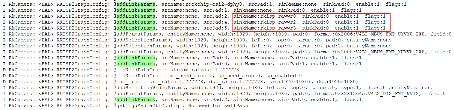
Original technical figure: EN V2.3, p107.
Editable transcription of fully visible screenshot text. Cropped edge characters are not reconstructed; fragments are not necessarily standalone executable examples.
I RkCamera: <HAL> RKISP2GraphConfig: @addLinkParams, srcName:rockchip-csi2-dphy0, srcPad:1, sinkName:none, sinkPad:0, enable:1, flags:1
I RkCamera: <HAL> RKISP2GraphConfig: @addLinkParams, srcName:none, srcPad:1, sinkName:none, sinkPad:0, enable:1, flags:1
I RkCamera: <HAL> RKISP2GraphConfig: @addLinkParams, srcName:none, srcPad:2, sinkName:rkisp_rawwr0, sinkPad:0, enable:1, flags:1
I RkCamera: <HAL> RKISP2GraphConfig: @addLinkParams, srcName:none, srcPad:4, sinkName:rkisp_rawwr2, sinkPad:0, enable:1, flags:1
I RkCamera: <HAL> RKISP2GraphConfig: @addLinkParams, srcName:none, srcPad:5, sinkName:rkisp_rawwr3, sinkPad:0, enable:1, flags:1
I RkCamera: <HAL> RKISP2GraphConfig: @addFormatParams, entityName:none, width:1920, height:1080, pad:0, format:0x2006:V4L2_MBUS_FMT_UYVY8_2X8, field:0
I RkCamera: <HAL> RKISP2GraphConfig: @addSelectionParams, width:1920, height:1080, left:0, top:0, target:0, pad:0, entityName:none
I RkCamera: <HAL> RKISP2GraphConfig: @addSelectionParams, width:1920, height:1080, left:0, top:0, target:0, pad:2, entityName:none
I RkCamera: <HAL> RKISP2GraphConfig: @addFormatParams, entityName:none, width:1920, height:1080, pad:2, format:0x2008:V4L2_MBUS_FMT_YUYV8_2X8, field:0
I RkCamera: <HAL> RKISP2GraphConfig: @addLinkParams, srcName:none, srcPad:3, sinkName:none, sinkPad:0, enable:1, flags:1
I RkCamera: <HAL> RKISP2GraphConfig: @addLinkParams, srcName:none, srcPad:0, sinkName:none, sinkPad:1, enable:1, flags:1
D RkCamera: <HAL> RKISP2GraphConfig: @ isNeedPathCrop : stream ratios: 1.777778
D RkCamera: <HAL> RKISP2GraphConfig: @ isNeedPathCrop : mp_need_crop 1, sp_need_crop 0, sp_enabled 0
D RkCamera: <HAL> RKISP2GraphConfig: @ calc_crop : src_ratio:1.777778, dst_ratio:1.777778, src(1920x1080), dst(1920x1080)
I RkCamera: <HAL> RKISP2GraphConfig: @addSelectionVideoParams, width:1920, height:1080, left:0, top:0, target:0, type:1, flags:0 entityName:none
I RkCamera: <HAL> RKISP2GraphConfig: @addFormatParams, entityName:none, width:1920, height:1080, pad:0, format:0x3231564e:V4L2_PIX_FMT_NV12, field:0
I RkCamera: <HAL> RKISP2GraphConfig: @addLinkParams, srcName:none, srcPad:2, sinkName:none, sinkPad:0, enable:1, flags:1
I RkCamera: <HAL> RKISP2GraphConfig: @getImguMediaCtlConfig : No need for selfPath
If the above log appears, cameraHAL has configured the corresponding pipeline to rkisp by default, whereas DTS configures it to rkcif. The source spells cameraHAL as ameraHAL here.
(3) Resolution
Add the following changes in hardware/rockchip/camera:
diff --git a/psl/rkisp2/RKISP2GraphConfig.cpp b/psl/rkisp2/RKISP2GraphConfig.cpp
index 2a5fa5a..3d2409c 100755
--- a/psl/rkisp2/RKISP2GraphConfig.cpp

+++ b/psl/rkisp2/RKISP2GraphConfig.cpp
@@ -76,6 +76,7 @@ const string MEDIACTL_POSTVIEWNAME = "postview";

 const string MEDIACTL_STATNAME = "rkisp1-statistics";
 const string MEDIACTL_VIDEONAME_CIF = "stream_cif_dvp_id0";
+const string MEDIACTL_VIDEONAME_CIF_MIPI_ID0 = "stream_cif_mipi_id0";

 RKISP2GraphConfig::RKISP2GraphConfig() :
      mManager(nullptr),
@@ -2620,6 +2621,13 @@ status_t RKISP2GraphConfig::getImguMediaCtlConfig(int32_t
cameraId,
            addLinkParams("rkisp-isp-subdev", 2, "rkisp_mainpath", 0, 1,
MEDIA_LNK_FL_ENABLED, mediaCtlConfig);

            addLinkParams("rkisp-isp-subdev", 2, "rkisp_selfpath", 0, 1,
MEDIA_LNK_FL_ENABLED, mediaCtlConfig);
         }
+     } else if(mipName2.find("mipi") != std::string::npos) {
+        addLinkParams(mipName, mipSrcPad, mipName2, csiSinkPad, 1,
MEDIA_LNK_FL_ENABLED, mediaCtlConfig);

+        addLinkParams(mipName2, 1, "stream_cif_mipi_id0", 0, 1,
MEDIA_LNK_FL_ENABLED, mediaCtlConfig);
+        addLinkParams(mipName2, 2, "stream_cif_mipi_id1", 0, 1,
MEDIA_LNK_FL_ENABLED, mediaCtlConfig);
+        addLinkParams(mipName2, 3, "stream_cif_mipi_id2", 0, 1,
MEDIA_LNK_FL_ENABLED, mediaCtlConfig);
+        addLinkParams(mipName2, 4, "stream_cif_mipi_id3", 0, 1,
MEDIA_LNK_FL_ENABLED, mediaCtlConfig);
+        mSensorLinkedToCIF = true;
      } else {
         addLinkParams(mipName, mipSrcPad, csiName, csiSinkPad, 1,
MEDIA_LNK_FL_ENABLED, mediaCtlConfig);

         addLinkParams(csiName, csiSrcPad, IspName, ispSinkPad, 1,
MEDIA_LNK_FL_ENABLED, mediaCtlConfig);
@@ -2628,6 +2636,12 @@ status_t RKISP2GraphConfig::getImguMediaCtlConfig(int32_t
cameraId,
         addLinkParams(csiName, 5, "rkisp_rawwr3", 0, 1,
MEDIA_LNK_FL_ENABLED, mediaCtlConfig);
      }
   }
+  if(mSensorLinkedToCIF){
+     addImguVideoNode(IMGU_NODE_VIDEO, MEDIACTL_VIDEONAME_CIF_MIPI_ID0,
mediaCtlConfig);
+     addFormatParams(MEDIACTL_VIDEONAME_CIF_MIPI_ID0, mCurSensorFormat.width,
mCurSensorFormat.height,

+           0, V4L2_PIX_FMT_NV12, 0, 0, mediaCtlConfig);
+     return OK;
+  }
   // isp input pad format and selection config
   addFormatParams(IspName, ispInWidth, ispInHeight, ispSinkPad, ispInFormat,
0, 0, mediaCtlConfig);
   addSelectionParams(IspName, ispInWidth, ispInHeight, 0, 0,
V4L2_SEL_TGT_CROP, ispSinkPad, mediaCtlConfig);
6.15.10 Operating RK628 GPIOs
Call the GPIO interface directly at the point where GPIO control is needed. This interface includes IOMUX selection, GPIO direction, and output-level configuration. For example, the following operations configure I2C_SDA_HDMI and I2C_SCL_HDMI as GPIOs.
rk628_gpio_direction_output(rk628, GPIO1_B1, GPIO_REG_HIGH);
rk628_gpio_direction_output(rk628, GPIO1_B2, GPIO_REG_HIGH);
To restore the original function, call the following interface:
rk628_pinctrl_set_mux(rk628, GPIO1_B1, DDCM0SDARX);
rk628_pinctrl_set_mux(rk628, GPIO1_B2, DDCM0SCLRX);
6.15.11 Sound-card registration failure
In the following example, the hdmiin sound card cannot be found after system startup:
# cat /proc/asound/cards
 1 [rockchiphdmiin ]: rockchip_hdmiin - rockchip,hdmiin
                rockchip,hdmiin
First check whether the soc dai and codec dai devices on which the sound card depends have loaded successfully:
rk3399:/ # cat /sys/kernel/debug/asoc/components
...
dummy-codec

ff8a0000.i2s
ff8a0000.i2s
ff880000.i2s
ff880000.i2s
...
rk3399:/ # cat /sys/kernel/debug/asoc/dais
...
ff8a0000.i2s
ff880000.i2s
dummy-codec
....
If these nodes fail to load, check defconfig and DTS.
If both soc dai and codec dai register successfully but the sound card does not, DMA resources may be insufficient. The source reports this especially frequently on RK3399. On kernels 4.19 and later, add the following property to the i2s node to address it:
--- a/arch/arm64/boot/dts/rockchip/rk3399.dtsi
+++ b/arch/arm64/boot/dts/rockchip/rk3399.dtsi

@@ -1788,6 +1788,7 @@
           clocks = <&cru SCLK_I2S2_8CH>, <&cru HCLK_I2S2_8CH>;
           resets = <&cru SRST_I2S2_8CH>, <&cru SRST_H_I2S2_8CH>;
           reset-names = "reset-m", "reset-h";
+          rockchip,capture-only;
           power-domains = <&power RK3399_PD_SDIOAUDIO>;
           status = "disabled";
7. Common requirements
7.1 Configuring an RK628 24M clock supplied by another SoC
The following examples describe configuration for several Rockchip host SoCs. All clocks configured in these DTS examples are assumed to be enabled in code. If they are not enabled, the 24M clock will be turned off after boot, causing I2C communication failures.
7.1.1 Adding 24M support on RK3399
(1) Reference the following configuration in the rk628 DTS:
pinctrl-names = "default";
pinctrl-0 = <&rk628_rst>, <&clk_testout2>;
assigned-clocks = <&cru SCLK_TESTCLKOUT2>;

assigned-clock-rates = <24000000>;
clocks = <&cru SCLK_TESTCLKOUT2>;
clock-names = "soc_24M";
(2) Add PINCTRL configuration for the I/O pins according to the actual hardware connections:
&pinctrl {
      test {
           clk_testout2: clk_testout2 {

           rockchip,pins = <0 8 RK_FUNC_3 &pcfg_pull_none>;
      };
};
7.1.2 Adding 24M support on RK3288
(1) Reference the following configuration in the rk628 DTS:
pinctrl-names = "default";
pinctrl-0 = <&test_clkout>;
assigned-clocks = <&cru SCLK_TESTOUT_SRC>;

assigned-clock-parents = <&xin24m>;
clocks = <&cru SCLK_TESTOUT>;
clock-names = "soc_24M";
(2) Add PINCTRL configuration for the I/O pins according to the actual hardware connections:
&pinctrl {
      test {
           test_clkout: test-clkout {

                 rockchip,pins = <0 17 RK_FUNC_1 &pcfg_pull_none>;
           };
      };
};
7.1.3 Adding 24M support on RK356X
RK356X has several pins capable of outputting 24 MHz, including REF_CLKOUT (clk_wifi/gpio0_a0), CAM_CLKOUT1 (clk_cam1_out/gpio4_b0), and ETH_REFCLK_25M_M0 (clk_mac1_out/gpio3_b0). The following example uses clk_wifi.
(1) Reference the following configuration in the rk628 DTS:
&i2c2_rk628 {
   pinctrl-names = "default";
   pinctrl-0 = <&rk628_reset &refclk_pins>;

   assigned-clocks = <&pmucru CLK_WIFI>;
   assigned-clock-rates = <24000000>;
   clocks = <&pmucru CLK_WIFI>;
   clock-names = "soc_24M";
};

&pinctrl {
   rk628 {
      rk628_reset: rk628-reset {
         rockchip,pins = <2 RK_PA2 RK_FUNC_GPIO &pcfg_pull_none>;
      };
   };

};
(2) The following configuration is already provided in rk3568-pinctrl.dtsi:
&pinctrl {
   ......

   refclk {
      /omit-if-no-ref/
      refclk_pins: refclk-pins {
         rockchip,pins =
           /* refclk_ou */
           <0 RK_PA0 1 &pcfg_pull_none>;
      };
   };
   ......
};
For Rockchip chips not listed here, refer to Rockchip_Develop_Guide_Gpio_Output_Clocks_CN.pdf for the 24M clock configuration.
7.2 Dual RK628 support
7.2.1 HDMI2CSI + HDMI2CSI support
7.2.1.1 Important considerations
(1) Two RK628 devices operate similarly to a dual-camera setup. For both RK628 devices to operate simultaneously, the host must support two ISP controllers that process two inputs concurrently, as on RK3399.
(2) In the hardware design, connect the two RK628 devices to different I2C buses, or to the same I2C bus with different I2C addresses.
(3) The DTS configuration must match the hardware design. Whether a particular RK628 is physically connected to mipi_phy_rx0 or mipi_phy_tx1rx1 must also be reflected in its DTS configuration.
(4) When using two RK628 devices for HDMI2CSI, their RESET and INT control I/Os must not be shared; otherwise operation will be abnormal.
7.2.1.2 Kernel DTS configuration
The following example configures two RK628 devices on RK3399.
(1) rk628 -> mipi_dphy_rx0 -> rkisp1_0: the first path has index 0 and facing set to back.
&i2c1 {
   status = "okay";


   rk628_csi_v4l2: rk628_csi_v4l2@50 {
      compatible = "rockchip,rk628-csi-v4l2";
      reg = <0x50>;
      //clocks = <&ext_cam_clk>;
      //clock-names = "xvclk";

      interrupt-parent = <&gpio4>;
      interrupts = <16 IRQ_TYPE_LEVEL_LOW>;
      pinctrl-names = "default";
      pinctrl-0 = <&rk628_irq>;
      //power-gpios = <&gpio0 RK_PD5 GPIO_ACTIVE_HIGH>;
      reset-gpios = <&gpio4 RK_PD2 GPIO_ACTIVE_LOW>;

      plugin-det-gpios = <&gpio0 RK_PD6 GPIO_ACTIVE_LOW>;
      rockchip,camera-module-index = <0>;
      rockchip,camera-module-facing = "back";
      rockchip,camera-module-name = "RK628-CSI";
      rockchip,camera-module-lens-name = "NC";
      port {
         rk628_out: endpoint {
           remote-endpoint = <&hdmi2mipi_in>;
           data-lanes = <1 2 3 4>;
         };
      };
   };

};

&mipi_dphy_rx0 {
   status = "okay";

   ports {
      #address-cells = <1>;
      #size-cells = <0>;

      port@0 {
         reg = <0>;
         #address-cells = <1>;
         #size-cells = <0>;


         hdmi2mipi_in: endpoint@1 {
           reg = <1>;
           remote-endpoint = <&rk628_out>;
           data-lanes = <1 2 3 4>;
         };
      };

      port@1 {
         reg = <1>;
         #address-cells = <1>;
         #size-cells = <0>;


         dphy_rx0_out: endpoint@0 {
           reg = <0>;
           remote-endpoint = <&isp0_mipi_in>;
         };
      };
   };
};

&rkisp1_0 {
   status = "okay";


   port {
      #address-cells = <1>;
      #size-cells = <0>;

      isp0_mipi_in: endpoint@0 {
         reg = <0>;
         remote-endpoint = <&dphy_rx0_out>;
      };
   };
};
(2) rk628 -> mipi_dphy_tx1rx1 -> rkisp1_1: the second path has index 1 and facing set to front.
&i2c4 {
   status = "okay";


   rk628_csi_v4l2_1: rk628_csi_v4l2_1@50 {
      compatible = "rockchip,rk628-csi-v4l2";
      reg = <0x50>;
      //clocks = <&ext_cam_clk>;
      //clock-names = "xvclk";

      interrupt-parent = <&gpio3>;
      interrupts = <12 IRQ_TYPE_LEVEL_LOW>;
      pinctrl-names = "default";
      pinctrl-0 = <&rk628_irq1>;
      //power-gpios = <&gpio0 RK_PD5 GPIO_ACTIVE_HIGH>;
      reset-gpios = <&gpio4 RK_PD3 GPIO_ACTIVE_LOW>;

      plugin-det-gpios = <&gpio0 RK_PD7 GPIO_ACTIVE_LOW>;
      rockchip,camera-module-index = <1>;
      rockchip,camera-module-facing = "front";
      rockchip,camera-module-name = "RK628-CSI";
      rockchip,camera-module-lens-name = "NC";
      port {
         rk628_out1: endpoint {
           remote-endpoint = <&hdmi2mipi_in1>;
           data-lanes = <1 2 3 4>;
         };
      };
   };
};

&mipi_dphy_tx1rx1 {

   status = "okay";

   ports {
      #address-cells = <1>;
      #size-cells = <0>;

      port@0 {
         reg = <0>;
         #address-cells = <1>;
         #size-cells = <0>;

         hdmi2mipi_in1: endpoint@1 {

           reg = <1>;
           remote-endpoint = <&rk628_out1>;
           data-lanes = <1 2 3 4>;
         };
      };

      port@1 {
         reg = <1>;
         #address-cells = <1>;
         #size-cells = <0>;

         dphy_tx1rx1_out: endpoint@0 {
           reg = <0>;

           remote-endpoint = <&isp1_mipi_in>;
         };
      };
   };
};

&rkisp1_1 {
   status = "okay";

   port {
      #address-cells = <1>;
      #size-cells = <0>;


      isp1_mipi_in: endpoint@0 {
         reg = <0>;
         remote-endpoint = <&dphy_tx1rx1_out>;
      };
   };
};
7.2.1.3 Android configuration
(1) Notes on camera3_profiles.xml configuration:
moduleId must match index in DTS.
First RK628:

Original technical figure: EN V2.3, p115.
Editable transcription of fully visible screenshot text. Cropped edge characters are not reconstructed; fragments are not necessarily standalone executable examples.
</Profiles>
<Profiles cameraId="0" name="rk628-csi" moduleId="m00">
    <Supported_hardware>
        <hwType value="SUPPORTED_HW_RKISP1"/>
    </Supported_hardware>
Second RK628:

Original technical figure: EN V2.3, p115.
Editable transcription of fully visible screenshot text. Cropped edge characters are not reconstructed; fragments are not necessarily standalone executable examples.
</Profiles>
<Profiles cameraId="1" name="rk628-csi" moduleId="m01">
    <Supported_hardware>
        <hwType value="SUPPORTED_HW_RKISP1"/>
    </Supported_hardware>
(2) To use both RK628 devices simultaneously, add cameraHAL support by making the following changes in SDK/hardware/rockchip/camera:
diff --git a/common/platformdata/PlatformData.cpp b/common/platformdata/PlatformData.cpp

index 36d2ac9..d3fcb4b 100755
--- a/common/platformdata/PlatformData.cpp
+++ b/common/platformdata/PlatformData.cpp
@@ -1047,7 +1047,7 @@ CameraHWInfo::CameraHWInfo() :
   mProductName = "<not_set>";
   mManufacturerName = "<not set>";
   mCameraDeviceAPIVersion = CAMERA_DEVICE_API_VERSION_3_3;
-  mSupportDualVideo = false;
+  mSupportDualVideo = true;
   mSupportExtendedMakernote = false;
   mSupportFullColorRange = true;
   mSupportIPUAcceleration = false;
7.2.2 HDMI2CSI + HDMI2DSI support
7.2.2.1 Kernel DTS configuration
In an HDMI2CSI + HDMI2DSI combination, one RK628 connects to the host through the camera framework, while the other RK628 connects to the display. The following example uses RK3399.
(1) HDMI2CSI configuration
Use rk628 -> mipi_phy_rx0 -> rkisp1_0 or rk628 -> mipi_dphy_tx1rx1 -> rkisp1_1. The example connects to rkisp1_0.
&i2c1 {
   status = "okay";


   rk628_csi_v4l2: rk628_csi_v4l2@50 {
      compatible = "rockchip,rk628-csi-v4l2";
      reg = <0x50>;
      //clocks = <&ext_cam_clk>;
      //clock-names = "xvclk";

      interrupt-parent = <&gpio4>;
      interrupts = <16 IRQ_TYPE_LEVEL_LOW>;
      pinctrl-names = "default";
      pinctrl-0 = <&rk628_irq>;
      //power-gpios = <&gpio0 RK_PD5 GPIO_ACTIVE_HIGH>;

      reset-gpios = <&gpio4 RK_PD2 GPIO_ACTIVE_LOW>;
      plugin-det-gpios = <&gpio0 RK_PD6 GPIO_ACTIVE_LOW>;
      rockchip,camera-module-index = <0>;
      rockchip,camera-module-facing = "back";
      rockchip,camera-module-name = "RK628-CSI";
      rockchip,camera-module-lens-name = "NC";
      port {
         rk628_out: endpoint {
            remote-endpoint = <&hdmi2mipi_in>;
            data-lanes = <1 2 3 4>;
         };
      };

   };
};

&mipi_dphy_rx0 {
   status = "okay";

   ports {
      #address-cells = <1>;
      #size-cells = <0>;

      port@0 {
         reg = <0>;
         #address-cells = <1>;

         #size-cells = <0>;

         hdmi2mipi_in: endpoint@1 {
            reg = <1>;
            remote-endpoint = <&rk628_out>;
            data-lanes = <1 2 3 4>;
         };
      };

      port@1 {
         reg = <1>;
         #address-cells = <1>;

         #size-cells = <0>;

         dphy_rx0_out: endpoint@0 {
            reg = <0>;
            remote-endpoint = <&isp0_mipi_in>;
         };
      };
   };
};

&rkisp1_0 {
   status = "okay";


   port {
      #address-cells = <1>;
      #size-cells = <0>;
      isp0_mipi_in: endpoint@0 {
         reg = <0>;

         remote-endpoint = <&dphy_rx0_out>;
      };
   };
};
(2) HDMI2DSI configuration
Refer directly to the HDMI2DSI conversion configuration in Section 2.4.5.
7.2.2.2 Android configuration
(1) HDMI2CSI: follow the configuration for a single RK628 HDMI2CSI path and configure camera3_profiles.xml correctly.
(2) HDMI2DSI: no Android-side configuration is required.