
This complete reference follows the 74-page Chinese V2.3.0 source, fully translated into English and Russian. No corresponding English PDF was supplied; all three versions use original Chinese-PDF figures, retaining their embedded labels. This is an ArmSoM platform reference. The source covers RK3576 Kernel 6.1 and RK3588 Kernel 5.10/6.1. Verify the actual board, SDK/BSP, panel, power sequencing and interface wiring. No board-level hardware validation was performed; universal ArmSoM board support is not claimed.
Examples, waveforms and measurements are from the source document, not ArmSoM tests. Register writes, PHY voltage/timing changes and patches can disrupt the display or system; no hardware commands were executed. Code, comments, commands and parameters retain the source text; source conflicts are not silently corrected.
Editorial notes · ArmSoM · Rockchip Linux
1. Introduction
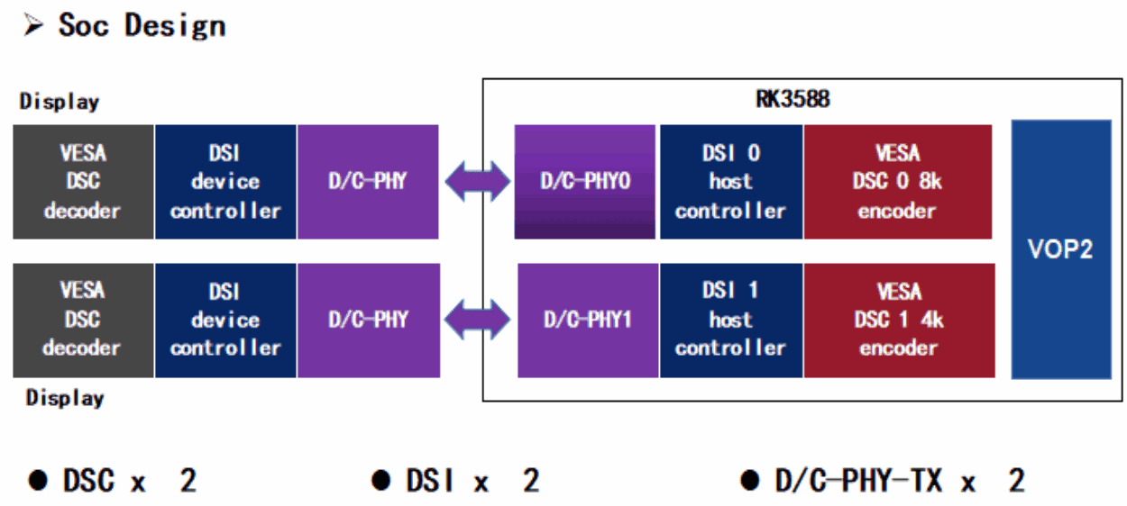
DSI-2 belongs to the set of communication protocols defined by the MIPI Alliance. DWC-MIPI-DSI2 is a digital controller core implementing all protocol functions defined in the MIPI-DSI2 specification. It supports the D-PHY and C-PHY physical interfaces and two Display Stream Compression (DSC) data paths.
2. MIPI-DSI2 Features
1. MIPI® Alliance Specification for Display Serial Interface 2 (DSI-2) Version 1.1
2. MIPI® Alliance Specification for Display Command Set (DCS) Version 1.4
3. MIPI® Alliance Specification for D-PHY v2.0
4. MIPI® Alliance Specification for C-PHY v1.1
5. Four data lanes on D-PHY and three data trios on C-PHY
6. Bidirectional communication and escape mode through data lane 0
7. Continuous and non-continuous clock modes on D-PHY and non-continuous clock mode on C-PHY
8. End of Transmission packet (EoTp)
9. Scrambling
10. VESA DSC 1.1/1.2a
11. Up to 4.5 Gbps per lane in D-PHY
12. Up to 2.0 Gsps per trio in C-PHY
3. Differences between the RK3576 and RK3588 DSI interfaces
| Feature | RK3576 | RK3588 |
|---|---|---|
| Dual channel | Not supported | Supported |
| Maximum resolution | 2560x1600@60Hz | 4096x2304@60Hz |
| Data lanes | 1/2/4 lanes | 1/2/4/8 lanes |
| Maximum lane rate | D-PHY: 2.5Gbps/lane C-PHY: 1.7Gsps/lane |
D-PHY: 4.5Gbps/lane C-PHY: 2.0Gsps/lane |
| Color format | RGB | RGB |
| Maximum color depth | 10 bit | 10 bit |
| DSC | Not supported | Supports VESA DSC 1.1/1.2a |
| C-PHY | Supported | Supported |
4. Differences between MIPI DSI-2 Host and MIPI DSI Host
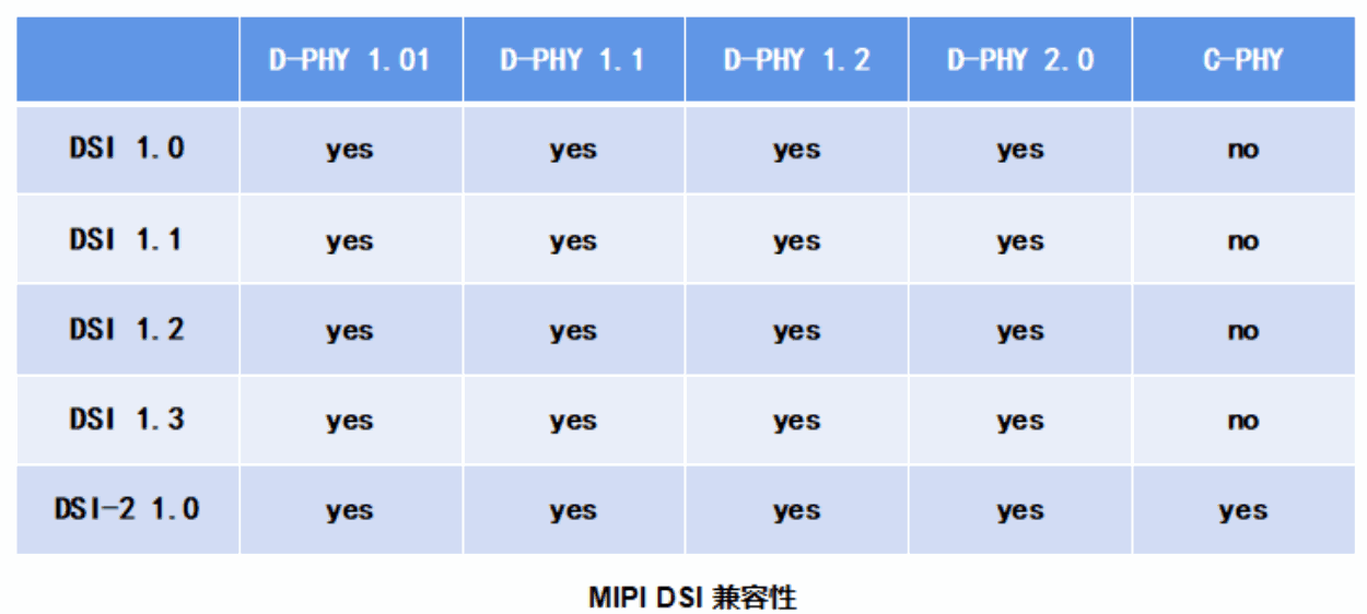
MIPI DSI-2 supports all MIPI DSI protocol functions and additionally supports MIPI C-PHY.
Editable transcription of the original figure:
| DSI | D-PHY 1.01 | D-PHY 1.1 | D-PHY 1.2 | D-PHY 2.0 | C-PHY 1.0 |
|---|---|---|---|---|---|
| DSI 1.0 | Yes | Yes | Yes | Yes | No |
| DSI 1.1 | Yes | Yes | Yes | Yes | No |
| DSI 1.2 | Yes | Yes | Yes | Yes | No |
| DSI 1.3 | Yes | Yes | Yes | Yes | No |
| DSI-2 1.0 | Yes | Yes | Yes | Yes | Yes |
5. MIPI DPHY differences
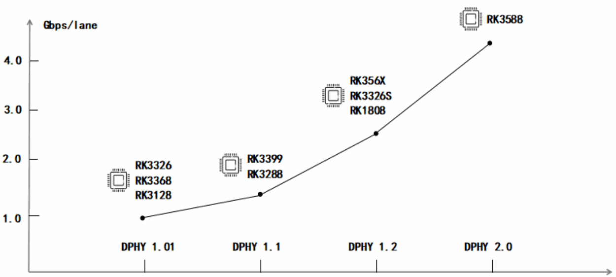
The RK3588 MIPI DPHY version differs from previous platforms and supports bandwidth up to 4.5 Gbps.
6. Applications
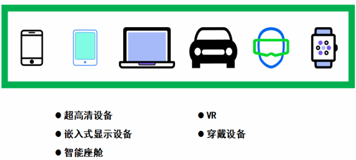
MIPI DSI uses differential signaling to reduce the pin count and hardware-design complexity while maintaining good hardware compatibility. IP based on MIPI DSI also features low power consumption and low EMI.
The following figure illustrates its application areas.
7. Driver code
7.1 U-Boot
7.1.1 Driver location
drivers/video/drm/dw_mipi_dsi2.c
drivers/video/drm/samsung_mipi_dcphy.c
7.1.2 Driver configuration
CONFIG_DRM_ROCKCHIP_DW_MIPI_DSI2=y
CONFIG_DRM_ROCKCHIP_SAMSUNG_MIPI_DCPHY=y
7.2 Kernel
7.2.1 Driver location
MIPI DSI-2 host controller:
drivers/gpu/drm/rockchip/dw-mipi-dsi2-rockchip.c
MIPI DCPHY:
drivers/phy/rockchip/phy-rockchip-samsung-dcphy.c
7.2.2 Driver configuration
cONFIG_ROCKCHIP_DW_MIPI_DSI=y
CONFIG_PHY_ROCKCHIP_SAMSUNG_DCPHY=y
7.2.3 Reference device trees
DTS paths:
arch/arm64/boot/dts/rockchip/rk3588-evb.dtsi
arch/arm64/boot/dts/rockchip/rk3588-evb1-lp4.dtsi
arch/arm64/boot/dts/rockchip/rk3588-evb2-lp4.dtsi
arch/arm64/boot/dts/rockchip/rk3588-evb3-lp5.dtsi
arch/arm64/boot/dts/rockchip/rk3588-evb4-lp4.dtsi
arch/arm64/boot/dts/rockchip/rk3588s-evb.dtsi
arch/arm64/boot/dts/rockchip/rk3588s-evb1-lp4x.dtsi
arch/arm64/boot/dts/rockchip/rk3588s-evb2-lp5.dtsi
arch/arm64/boot/dts/rockchip/rk3588s-evb4-lp4x.dtsi
DTS configuration scenarios:
rk3588-evb1: dsi0->dphy->1080p_panel && dsi1->dphy->1080p_panel;
rk3588-evb2: dsi1->dphy->1080p_panel;
rk3588-evb3: dsi0->dphy->1080p_panel && dsi1->cphy->cphy_panel;
rk3588-evb4: dsi0->dphy->1080p_panel;
rk3588s-evb1: dsi0->dphy->1080p_panel && dsi1->dphy->cmd_no_dsc_panel;
rk3588s-evb2: dsi0->cphy->cphy_panel & dsi1->dphy->1080p_panel;
rk3588s-evb4: dsi0->dphy->1080p_panel && dsi1->dphy->cmd_dsc_panel;
8. DSI controller and panel configuration
8.1 DTS configuration
&dsi0 {
    status = "okay";
    //rockchip,lane-rate = <1000>;
    //auto-calculation-mode;
    //disable-hold-mode;
    //support-psr;
};
&dsi0_panel {
    status = "okay";
    compatible = "simple-panel-dsi";
    reg = <0>;
    power-supply = <&vcc3v3_lcd_n>;
    backlight = <&backlight>;
    reset-gpios = <&gpio2 RK_PB4 GPIO_ACTIVE_LOW>;
    reset-delay-ms = <10>;
    enable-delay-ms = <10>;
    prepare-delay-ms = <10>;
    unprepare-delay-ms = <10>;
    disable-delay-ms = <60>;
    dsi,flags = <(MIPI_DSI_MODE_VIDEO | MIPI_DSI_MODE_VIDEO_BURST |
        MIPI_DSI_MODE_LPM | MIPI_DSI_MODE_EOT_PACKET)>;
    dsi,format = <MIPI_DSI_FMT_RGB888>;
    dsi,lanes = <4>;
    //phy-c-option;
    //compressed-data;
    //slice-width = <720>;
    //slice-height = <65>;
    //version-major = <1>;
    //version-minor = <1>;
    panel-init-sequence = [
        ...
        05 78 01 11
        05 00 01 29
    ];
    panel-exit-sequence = [
        05 00 01 28
        05 00 01 10
    ];
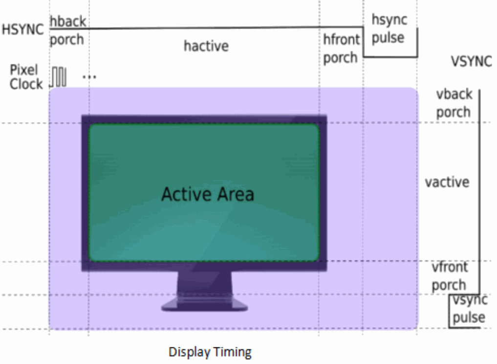
    disp_timings0: display-timings {
        native-mode = <&dsi0_timing0>;
        dsi0_timing0: timing0 {
            clock-frequency = <132000000>;
            hactive = <1080>;
            vactive = <1920>;
            hfront-porch = <15>;
            hsync-len = <4>;
            hback-porch = <30>;
            vfront-porch = <15>;
            vsync-len = <2>;
            vback-porch = <15>;
            hsync-active = <0>;
            vsync-active = <0>;
            de-active = <0>;
            pixelclk-active = <0>;
        };
    };
};
8.2 Configuration details
8.2.1 General configuration
| Property | Description | Value |
|---|---|---|
| rockchip,lane-rate | Manually specify the MIPI lane rate | Supported units: D-PHY: Mbps/lane or Kbps/lane C-PHY: Msps/lane or Ksps/lane For 800Mbps: rockchip,lane-rate = <800>; or rockchip,lane-rate = <800000>; |
| auto-calculation | Enable Auto-Calculation mode | Boolean-type string (source wording) |
| disable-hold-mode | Allow frame updates without configuring TE | Boolean-type string (source wording) |
| support-psr | Enable PSR | Boolean-type string (source wording) |
| compatible | compatible | simple-panel-dsi |
| power-supply | Panel power supply [optional] | Reference to the associated regulator |
| backlight | Backlight | Backlight reference |
| enable-gpios | Panel-enable GPIO [optional] | GPIO reference |
| reset-gpios | Panel-reset GPIO | GPIO reference |
| reset-delay-ms | panel sequence delay |
See the panel specification |
| enable-delay-ms | panel sequence delay |
See the panel specification |
| prepare-delay-ms | panel sequence delay |
See the panel specification |
| unprepare-delay-ms | panel sequence delay |
See the panel specification |
| disable-delay-ms | panel sequence delay |
See the panel specification |
| dsi,flags | DSI2 operating mode | cmd mode: MIPI_DSI_MODE_LPM | MIPI_DSI_MODE_EOT_PACKET |
| dsi,flags | DSI2 operating mode | video mode: MIPI_DSI_MODE_VIDEO | MIPI_DSI_MODE_VIDEO_BURST | MIPI_DSI_MODE_LPM | MIPI_DSI_MODE_EOT_PACKET |
| dsi,format | Pixel data format | MIPI_DSI_FMT_RGB888 |
| dsi,format | Pixel data format | MIPI_DSI_FMT_RGB666 |
| dsi,format | Pixel data format | MIPI_DSI_FMT_RGB666_PACKED |
| dsi,format | Pixel data format | MIPI_DSI_FMT_RGB565 |
| dsi,lanes | Number of MIPI data lanes | 1/2/3 trios [cphy] |
| dsi,lanes | Number of MIPI data lanes | 6 trios [dual-channel CPHY] |
| dsi,lanes | Number of MIPI data lanes | 1/2/3/4 lanes [dphy] |
| dsi,lanes | Number of MIPI data lanes | 8 lanes [dual-channel DPHY] |
| phy-c-option | C-PHY panel [option] | Boolean-type string (source wording) |
| compressed-data | Panel with DSC [optional] | Boolean-type string (source wording) |
| slice-width | DSC slice width [optional] | See the panel specification |
| slice-height | DSC slice height [optional] | See the panel specification |
| version-major | DSC version [optional] | See the panel specification |
| version-minor | DSC version [optional] | See the panel specification |
| panel-init-sequence | Panel power-on initialization sequence | [hex] data_type delay_ms payload_lenth payload |
| panel-exit-sequence | Panel power-off sequence | [hex] data_type delay_ms payload_lenth payload |
| display-timing | Panel timing | See the panel specification |
8.2.2 Display timing
8.2.3 dsi,flags
8.2.3.1 Clock type
Section 5.6.1, Clock Requirements, of the MIPI DSI specification states that every DSI transmitter and receiver must support continuous clock operation on the clock lane and may optionally support non-continuous operation. The peripheral requirements therefore determine whether the clock lane operates continuously or non-continuously in a display application.
By default, the MIPI DPHY clock lane operates continuously, a behavior supported by both master and slave in a DSI display system. If the peripheral relies on the host clock, the clock lane must operate continuously, as illustrated below.
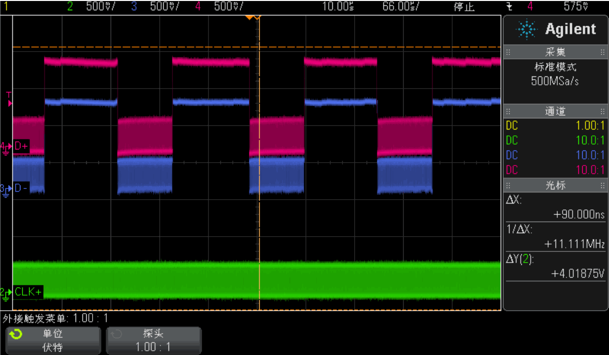
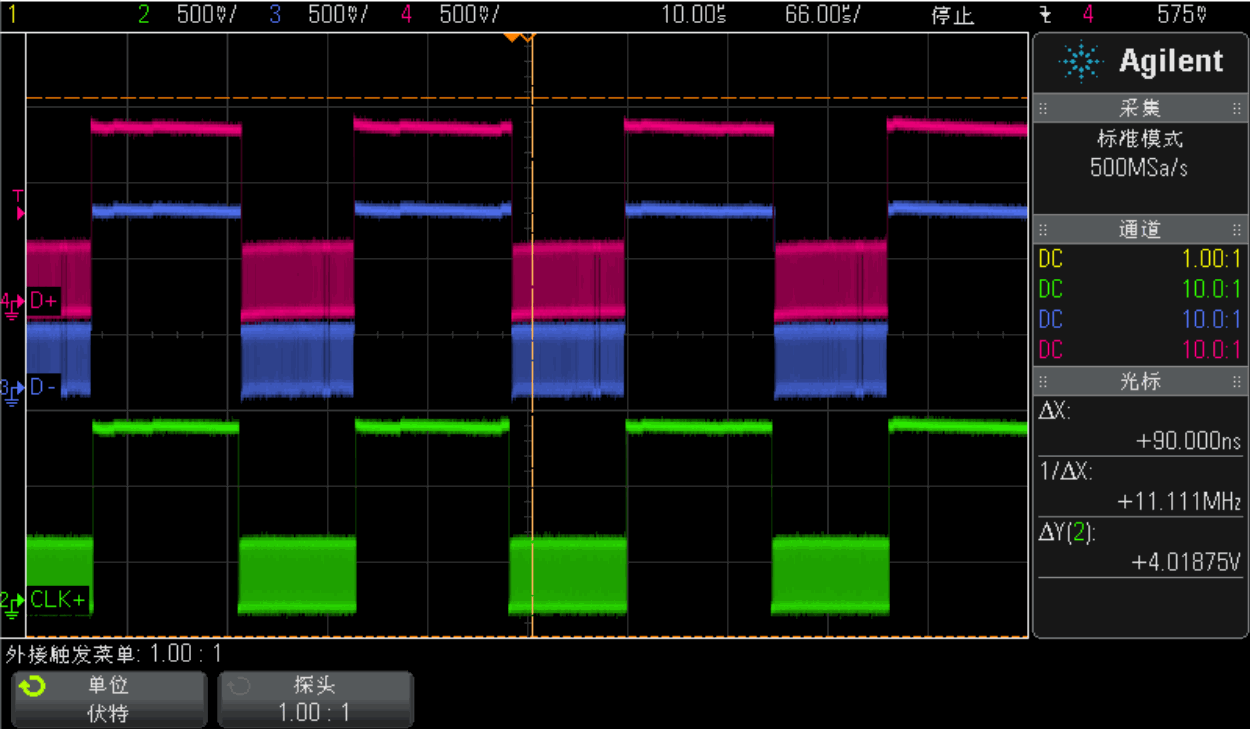
When saving power is important, particularly during transmission, non-continuous clock mode avoids wasting power when data transfer is unnecessary. Append MIPI_DSI_CLOCK_NON_CONTINUOUS to dsi,flags to configure the MIPI DPHY clock lane for non-continuous operation, as illustrated below.
8.2.3.2 Eotp
DSI specification V1.0 and earlier do not support Eotp. Devices conforming to specifications newer than V1.0 must support Eotp generation and detection. The source describes the RK3588/RK3576 DSI version here as V2.0. For interoperability with older devices, the host must be able to enable or disable generation and detection. Ultimately, whether to enable Eotp depends on panel support.
Eotp is a short packet indicating the end of high-speed transmission on the data link. Its main purpose is to improve the robustness of high-speed communication; DSI therefore need not send Eotp in LP mode.
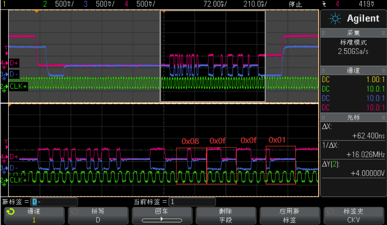
Unlike other DSI packets, Eotp has a fixed format:
Data Type = DI [5:0] = 0b001000
Virtual Channel = DI [7:6] = 0b00
Payload Data [15:0] = 0x0F0F
ECC [7:0] = 0x01
Appending MIPI_DSI_MODE_EOT_PACKET to dsi,flags controls whether the SoC MIPI DSI TX sends Eotp in high-speed mode. The following waveform captures Eotp in HSDT mode.
8.2.3.3 BLANK_HS_EN
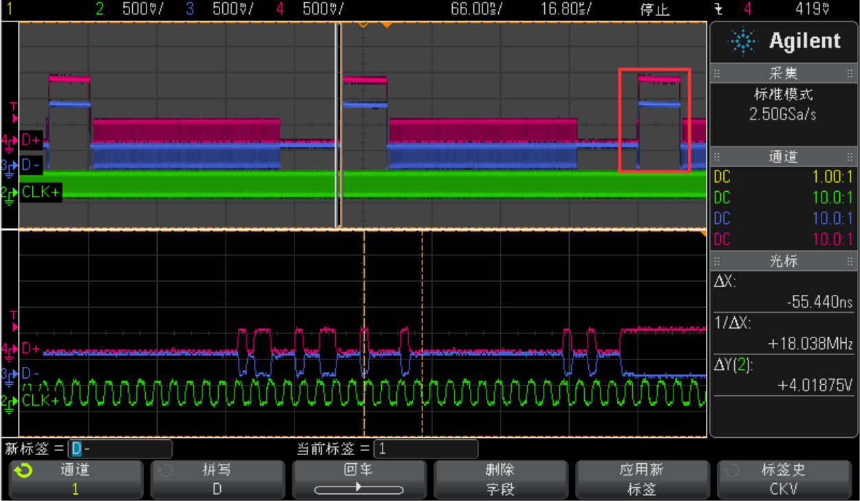
On a data lane, a line generally contains two LP11 blanking intervals, as shown below.
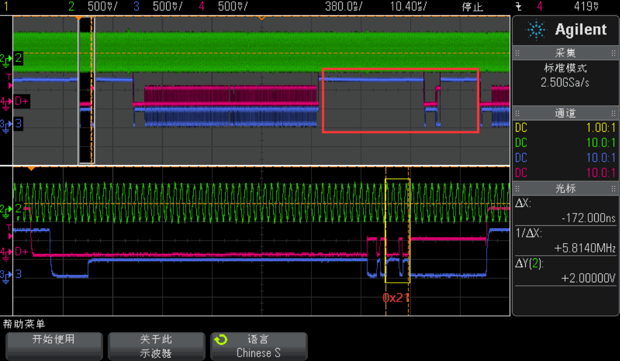
Some display modules or external MIPI bridge chips do not support two LP-11 intervals during Hblank. Append BLK_HFP_HS_EN or BLK_HBP_HS_EN to dsi,flags so that HFP or HBP remains in high-speed mode.
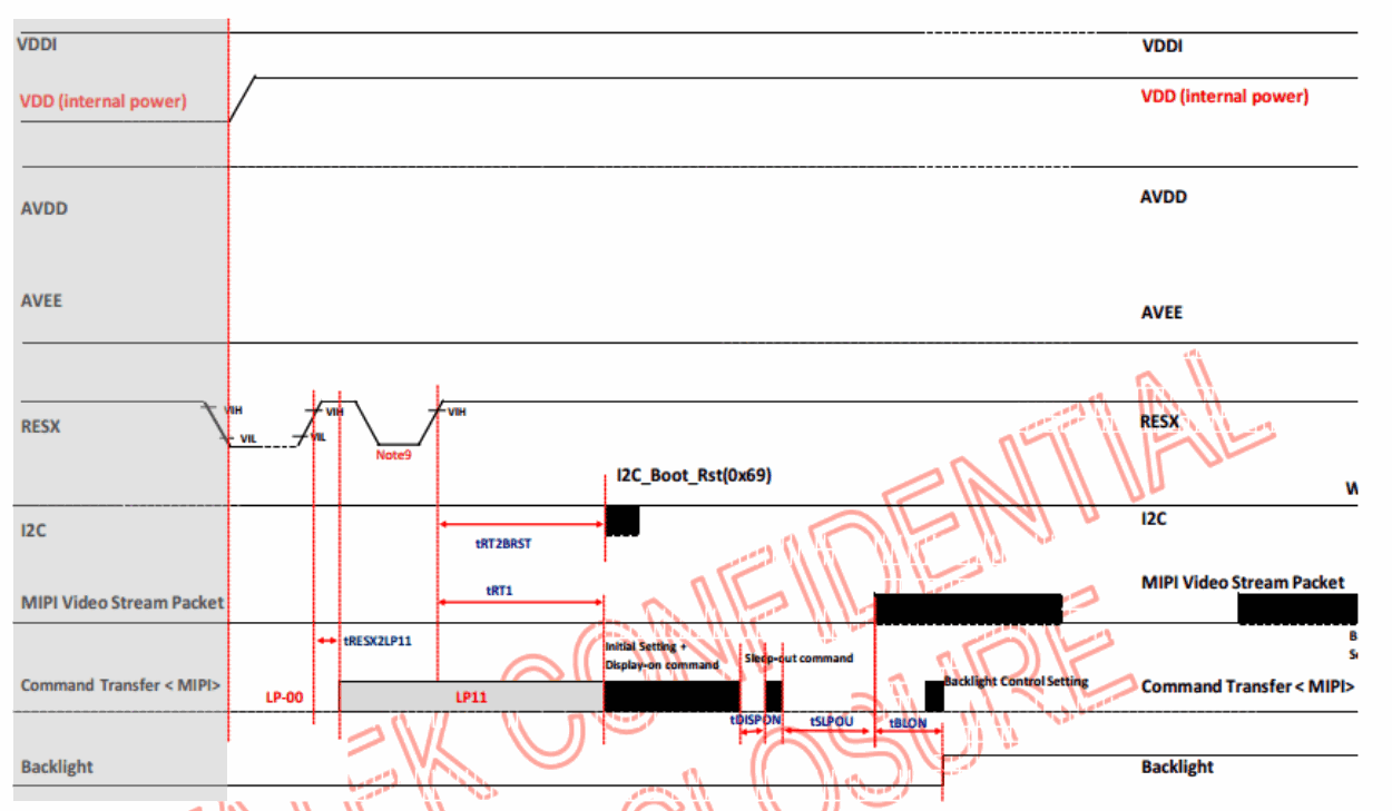
8.2.4 Panel power-on sequence
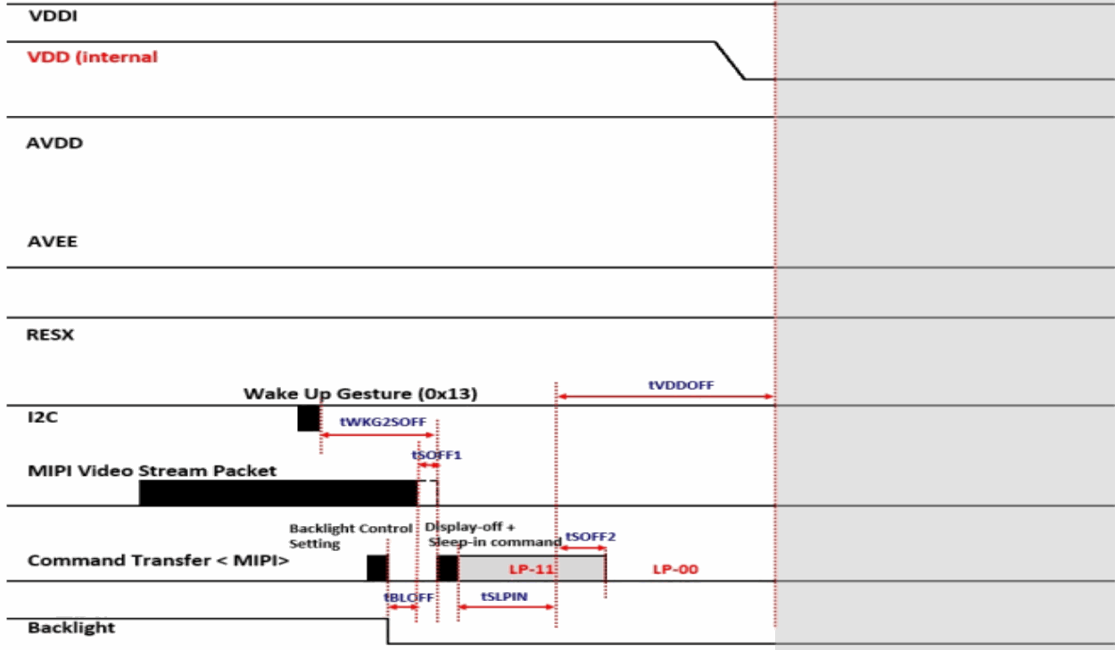
8.2.5 Panel power-off sequence
8.2.6 Common initialization-sequence data types
| Data type | Description | Packet size |
|---|---|---|
| 0x03 | Generic Short WRITE, no parameters | Short |
| 0x13 | Generic Short WRITE, 1 parameter | Short |
| 0x23 | Generic Short WRITE, 2 parameters | Short |
| 0x29 | Generic long WRITE | Long |
| 0x05 | DCS Short WRITE, no parameters | Short |
| 0x15 | DCS Short WRITE, 1 parameter | Short |
| 0x07 | DCS Short WRITE, 1 parameter, DSC EN | Short |
| 0x0a | DCS long WRITE, PPS, 128 bytes | Long |
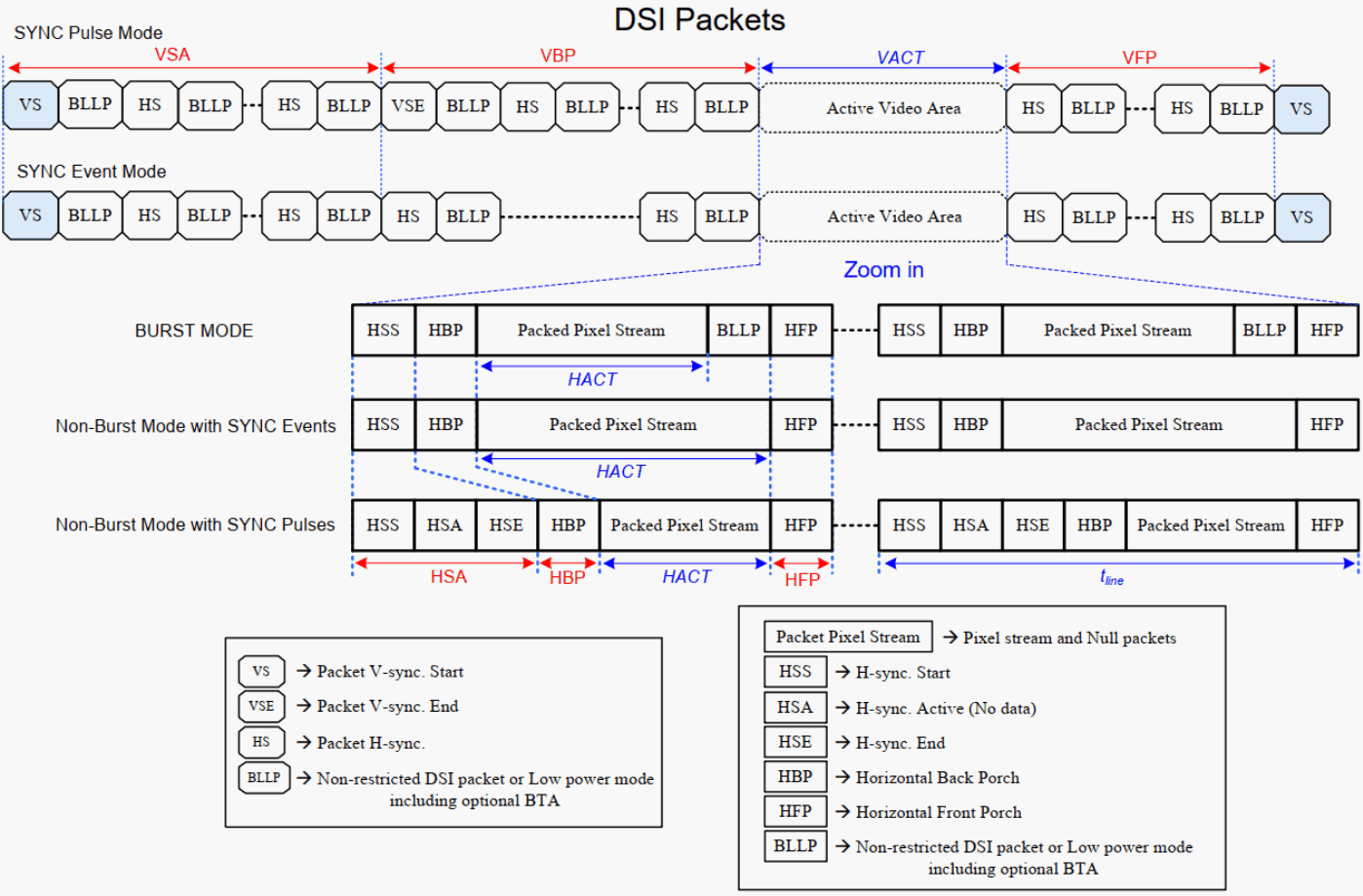
9. Timing for DSI video mode
10. Bandwidth
The MIPI DSI driver automatically calculates bandwidth for each operating mode using the following formulas. During debugging, use rockchip,lane-rate in the DTS dsi node to fine-tune the result. Units may be Kbps/Mbps for D-PHY or Ksps/Msps for C-PHY. The following examples show that RK3588 MIPI DSI DPHY can support 4K@60 without DSC, whereas CPHY slightly exceeds its maximum bandwidth.
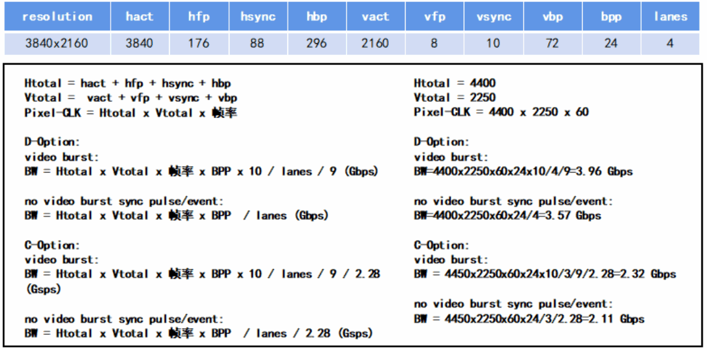
Editable transcription of the original figure:
| Parameter | Value |
|---|---|
| Resolution | 3840x2160 |
| hact / hfp / hsync / hbp | 3840 / 176 / 88 / 296 |
| vact / vfp / vsync / vbp | 2160 / 8 / 10 / 72 |
| bpp / lanes | 24 / 4 |
Htotal = hact + hfp + hsync + hbp = 4400
Vtotal = vact + vfp + vsync + vbp = 2250
Pixel-CLK = Htotal * Vtotal * framerate = 4400 * 2250 * 60
D-PHY Video Burst: BW = Htotal * Vtotal * framerate * BPP * 10 / lanes / 9
= 4400 * 2250 * 60 * 24 * 10 / 4 / 9 = 3.96 Gbps
D-PHY Non Burst Sync Pulse/Event: BW = Htotal * Vtotal * framerate * BPP / lanes
= 4400 * 2250 * 60 * 24 / 4 = 3.57 Gbps
C-PHY Video Burst: BW = Htotal * Vtotal * framerate * BPP * 10 / lanes / 9 / 2.28
= 4450 * 2250 * 60 * 24 * 10 / 3 / 9 / 2.28 = 2.32 Gbps
C-PHY Non Burst Sync Pulse/Event: BW = Htotal * Vtotal * framerate * BPP / lanes / 2.28
= 4450 * 2250 * 60 * 24 / 3 / 2.28 = 2.11 Gbps
The original C-PHY substitutions use 4450 rather than Htotal=4400. Their result unit is Gbps, while the text uses Gsps for C-PHY. Both discrepancies are preserved; these are neither measured results nor corrected calculations.
11. DSC
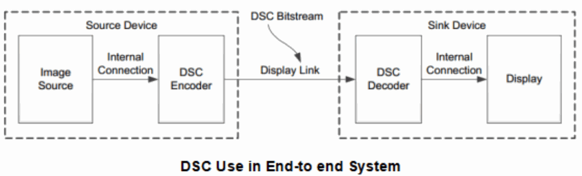
DSC means Display Stream Compression. The following diagram shows a complete DSC system operating in real time. Uncompressed pixels enter the encoder in raster-scan order; its output bitstream travels through the display link to the decoder in real time. The decoder reconstructs the video pixels and sends them to the display module. The decoded image has the same data format as the image entering the encoder. RK3588 has two DSC encoders, enabling high-resolution content to be transmitted at low bandwidth and low latency and allowing MIPI DSI to drive higher-resolution displays.
11.1 Slice
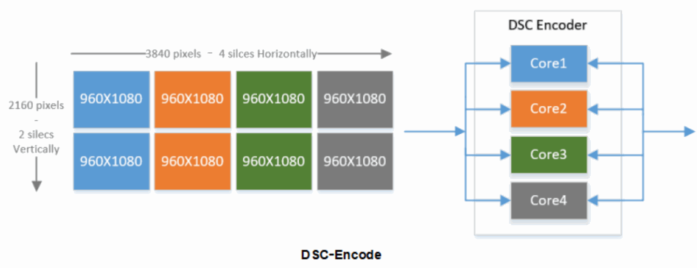
To accelerate encoding and reduce compression distortion, DSC divides every frame into slices that are encoded concurrently. It can support 1, 2, 4, 8 or more slices. The unit is slices/line: a line means one raster-scan line of pixels. Slice width and height may also vary. The upper-right and lower-right examples below both contain four slices per line, but the upper example uses long strips and the lower example shorter rectangles. Slice geometry depends on the slice counts supported by the source and sink DSC implementations and their compression/decompression rates. RK3588 DSC0 supports up to 8 slices and DSC1 up to 2 slices.
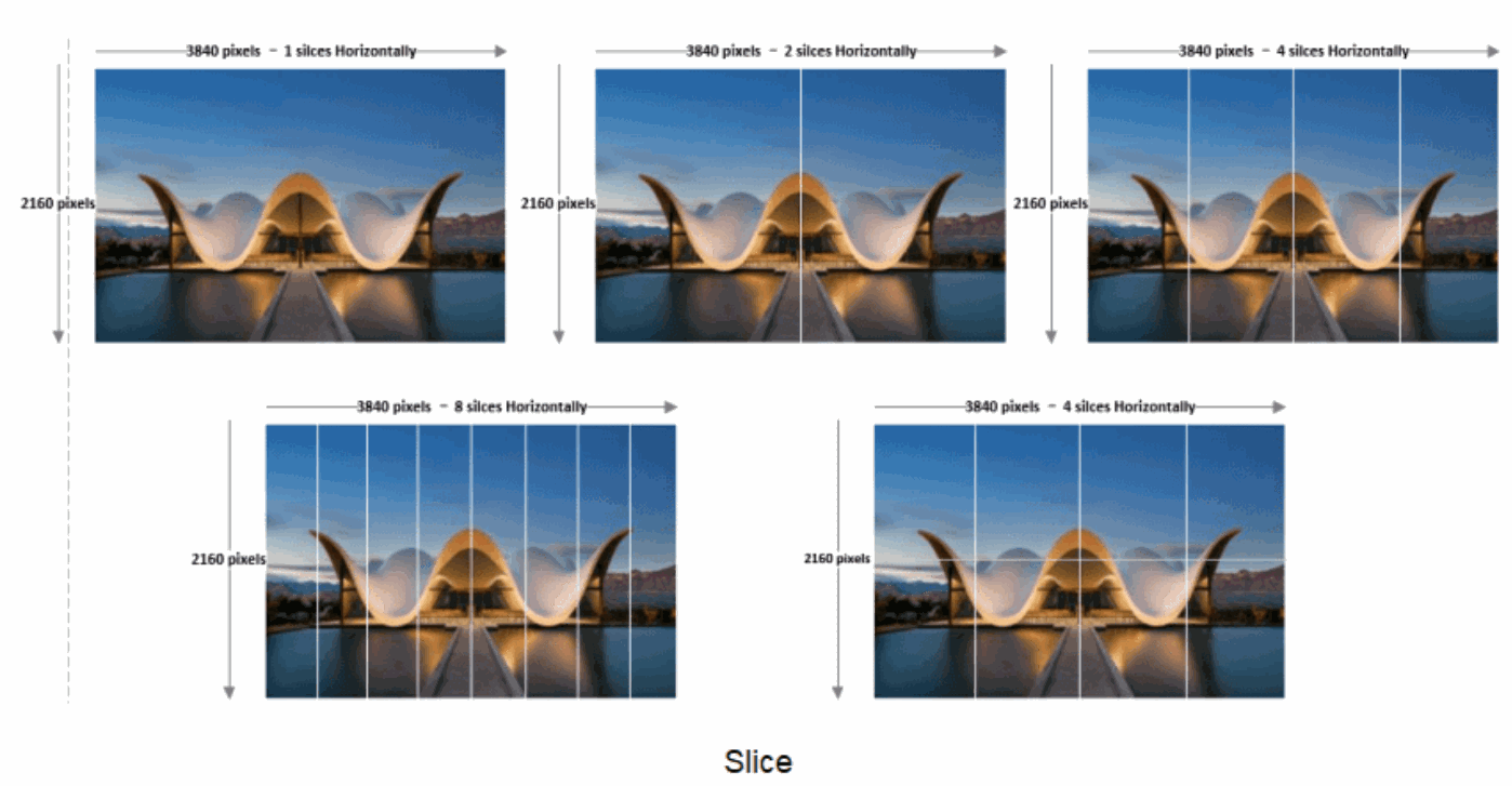
To determine whether RK3588 DSC supports a particular resolution and slice count, use the following formulas:
DSC_8K: active_slice_num * slice_width <= 960 * 8
DSC_4K: active_slice_num * slice_width <= 2048 * 2
11.2 DSC encoding
Before compression, the source and sink agree on a supported slice count and divide the image into equal grid regions. For a 3840x2160 image, if both devices support 8 slices, it can be divided into four columns and two rows. If the DSC encoder has four independent parallel compression cores, the eight slices shown on the left can be arranged into four groups and compressed concurrently, transmitting 4K content at low bandwidth and low latency.
11.3 DSC bandwidth
For 4Kp60, the following table compares MIPI D/C-PHY bandwidth before and after enabling DSC. DSC can reduce link bandwidth to one-third to one-half of the uncompressed requirement.
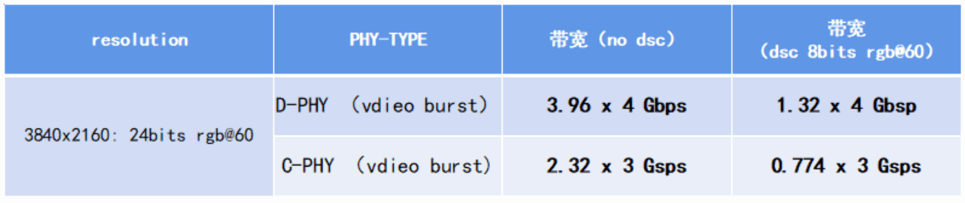
Editable transcription of the original figure:
| 3840x2160 / 60Hz | 24 bits RGB | DSC 8 bits RGB |
|---|---|---|
| D-PHY Video Burst | 3.96 x 4 Gbps | 1.32 x 4 Gbps |
| C-PHY Video Burst | 2.32 x 3 Gsps | 0.774 x 3 Gsps |
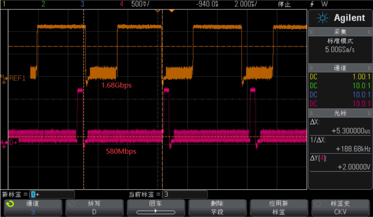
The following source waveforms were measured when RK3588 MIPI DSI drove a 1440x3120p60, 4-lane display module with DSC, using the original bandwidth and one-third of that bandwidth respectively.
11.4 PPS
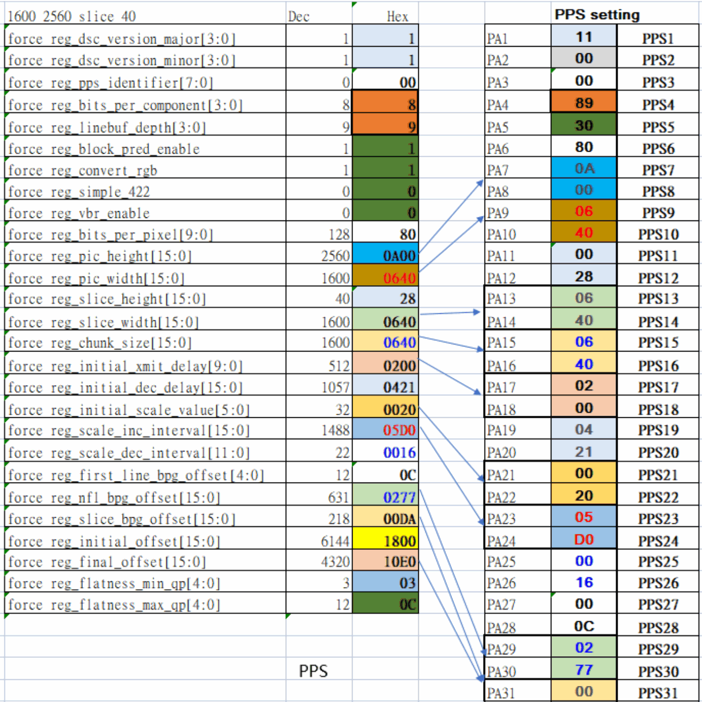
PPS is 128 bytes long. The following table describes important information required by the DSC system:
1. DSC version;
2. BPC before DSC compression;
3. BPP after DSC compression;
4. Original input-image width and height before compression;
5. DSC slice width and height.
Editable transcription of the original figure:
PPS example: 1600 × 2560, slice 40. The following transcribes all fully visible fields and PA1–PA31; subsequent PPS bytes absent from the source figure are not inferred.
| Field | Dec | Hex |
|---|---|---|
| force_reg_dsc_version_major[3:0] | 1 | 1 |
| force_reg_dsc_version_minor[3:0] | 1 | 1 |
| force_reg_pps_identifier[7:0] | 0 | 00 |
| force_reg_bits_per_component[3:0] | 8 | 8 |
| force_reg_linebuf_depth[3:0] | 9 | 9 |
| force_reg_block_pred_enable | 1 | 1 |
| force_reg_convert_rgb | 1 | 1 |
| force_reg_simple_422 | 0 | 0 |
| force_reg_vbr_enable | 0 | 0 |
| force_reg_bits_per_pixel[9:0] | 128 | 80 |
| force_reg_pic_height[15:0] | 2560 | 0A00 |
| force_reg_pic_width[15:0] | 1600 | 0640 |
| force_reg_slice_height[15:0] | 40 | 28 |
| force_reg_slice_width[15:0] | 1600 | 0640 |
| force_reg_chunk_size[15:0] | 1600 | 0640 |
| force_reg_initial_xmit_delay[9:0] | 512 | 0200 |
| force_reg_initial_dec_delay[15:0] | 1057 | 0421 |
| force_reg_initial_scale_value[5:0] | 32 | 0020 |
| force_reg_scale_inc_interval[15:0] | 1488 | 05D0 |
| force_reg_scale_dec_interval[11:0] | 22 | 0016 |
| force_reg_first_line_bpg_offset[4:0] | 12 | 0C |
| force_reg_nfl_bpg_offset[15:0] | 631 | 0277 |
| force_reg_slice_bpg_offset[15:0] | 218 | 00DA |
| force_reg_initial_offset[15:0] | 6144 | 1800 |
| force_reg_final_offset[15:0] | 4320 | 10E0 |
| force_reg_flatness_min_qp[4:0] | 3 | 03 |
| force_reg_flatness_max_qp[4:0] | 12 | 0C |
| PA | Hex | PPS |
|---|---|---|
| PA1 | 11 | PPS1 |
| PA2 | 00 | PPS2 |
| PA3 | 00 | PPS3 |
| PA4 | 89 | PPS4 |
| PA5 | 30 | PPS5 |
| PA6 | 80 | PPS6 |
| PA7 | 0A | PPS7 |
| PA8 | 00 | PPS8 |
| PA9 | 06 | PPS9 |
| PA10 | 40 | PPS10 |
| PA11 | 00 | PPS11 |
| PA12 | 28 | PPS12 |
| PA13 | 06 | PPS13 |
| PA14 | 40 | PPS14 |
| PA15 | 06 | PPS15 |
| PA16 | 40 | PPS16 |
| PA17 | 02 | PPS17 |
| PA18 | 00 | PPS18 |
| PA19 | 04 | PPS19 |
| PA20 | 21 | PPS20 |
| PA21 | 00 | PPS21 |
| PA22 | 20 | PPS22 |
| PA23 | 05 | PPS23 |
| PA24 | D0 | PPS24 |
| PA25 | 00 | PPS25 |
| PA26 | 16 | PPS26 |
| PA27 | 00 | PPS27 |
| PA28 | 0C | PPS28 |
| PA29 | 02 | PPS29 |
| PA30 | 77 | PPS30 |
| PA31 | 00 | PPS31 |
11.5 Examples
11.5.1 When to enable DSC
The following customer-provided display-module parameters illustrate when DSC can be enabled in a MIPI DSI display project:
1. The module has a DPHY interface with 4 data lanes, supporting up to 1Gbps/lane;
2. It uses Video Burst mode; original bandwidth: 1.866Gbps, 24-bit RGB, 60 frames/s;
3. It supports DSC with 1 slice;
4. Its target rate is 676Mbps/lane.
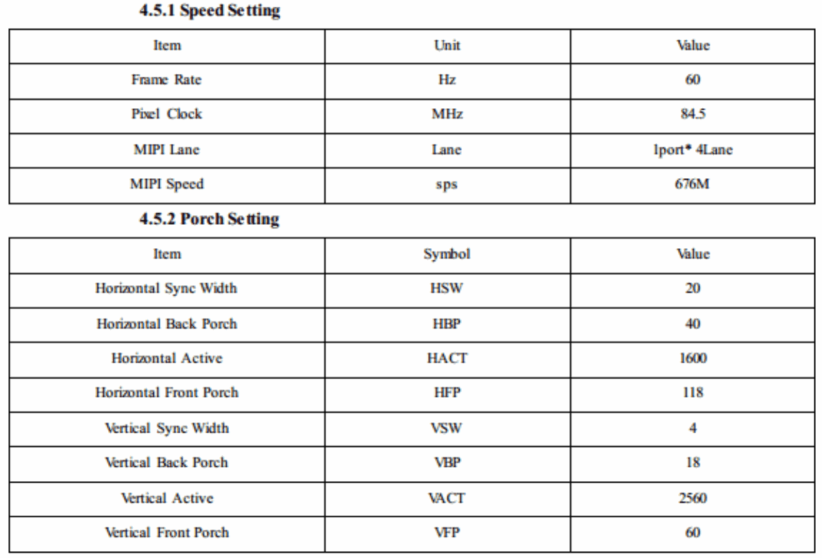
Editable transcription of the original figure:
| Parameter | Value |
|---|---|
| Frame Rate | 60 Hz |
| Pixel Clock | 84.5 MHz |
| MIPI Lane | 1 port * 4 Lane |
| MIPI Speed | 676 M sps |
| HSW / HBP / HACT / HFP | 20 / 40 / 1600 / 118 |
| VSW / VBP / VACT / VFP | 4 / 18 / 2560 / 60 |
11.5.2 Enabling DSC for dual-channel MIPI
The following diagram shows the display path in a customer design using a 2560x2560p120 dual-MIPI display module with DSC.
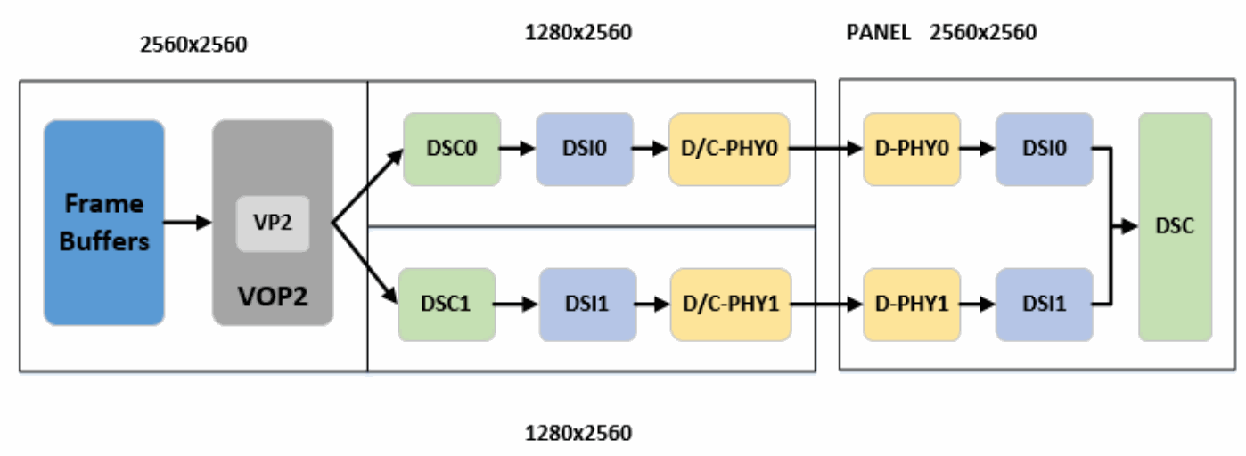
12. Display route
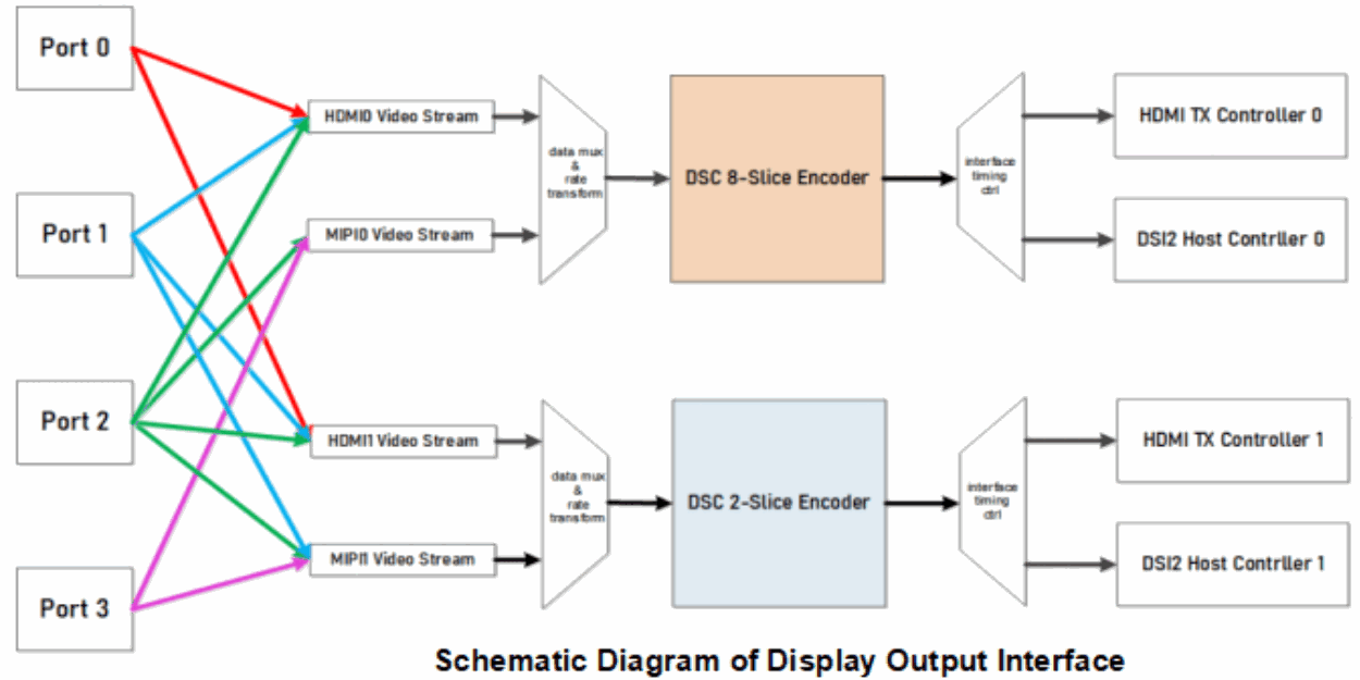
12.1 MIPI with DSC
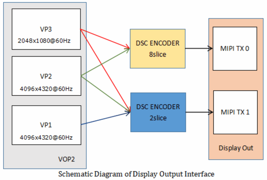
12.2 MIPI with DSC bypass
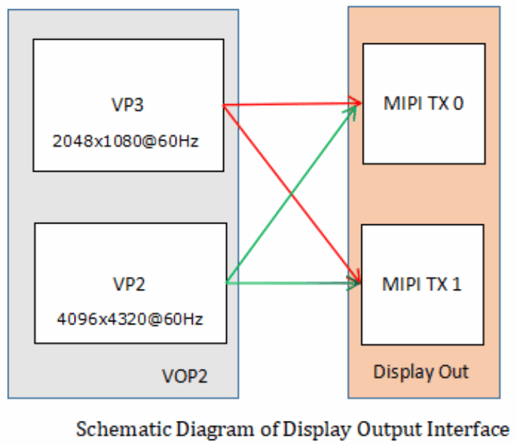
12.3 DTS configuration
Example: DSI0 attached to VP3:
&dsi0_in_vp2 {
    status = "disabled";
};
&dsi0_in_vp3 {
    status = "okay";
};
Example: DSI1 attached to VP2:
&dsi1_in_vp2 {
    status = "okay";
};
&dsi1_in_vp3 {
    status = "disabled";
};
13. Boot logo
13.1 route_dsi0
For example, vp3->dsi0 or vp3->dsc0->dsi0:
&route_dsi0 {
    status = "okay";
    connect = <&vp3_out_dsi0>;
};
13.2 route_dsi1
For example, vp2->dsi1 or vp2->dsc1->dsi1:
&route_dsi1 {
    status = "okay";
    connect = <&vp2_out_dsi1>;
};
13.3 route_dsi0 && route_dsi1
For example, (vp3->dsi0 or vp3->dsc0->dsi0) && (vp2->dsi1 or vp2->dsc1->dsi1):
&route_dsi0 {
    status = "okay";
    connect = <&vp3_out_dsi0>;
};
&route_dsi1 {
    status = "okay";
    connect = <&vp2_out_dsi1>;
};
14. DSI HOST
DSI supports Manual and Auto-Calculation modes. The driver defaults to Manual; users may choose Auto-Calculation, which has the following characteristics.
The host automatically extracts all necessary information and timing parameters from the IPI and PPI interfaces to satisfy video-mode frame timing. Auto-Calculation offers these advantages:
No register set needs to be configured by the user.
It simplifies configuration and reduces the likelihood of unexpected controller behavior.
It allows IPI frames to change dynamically while the controller adapts its output frames.
In the following examples, ports links the Display Interface to the panel. Refer to this document for configuration details:
Documentation/devicetree/bindings/graph.txt
14.1 Single DSI
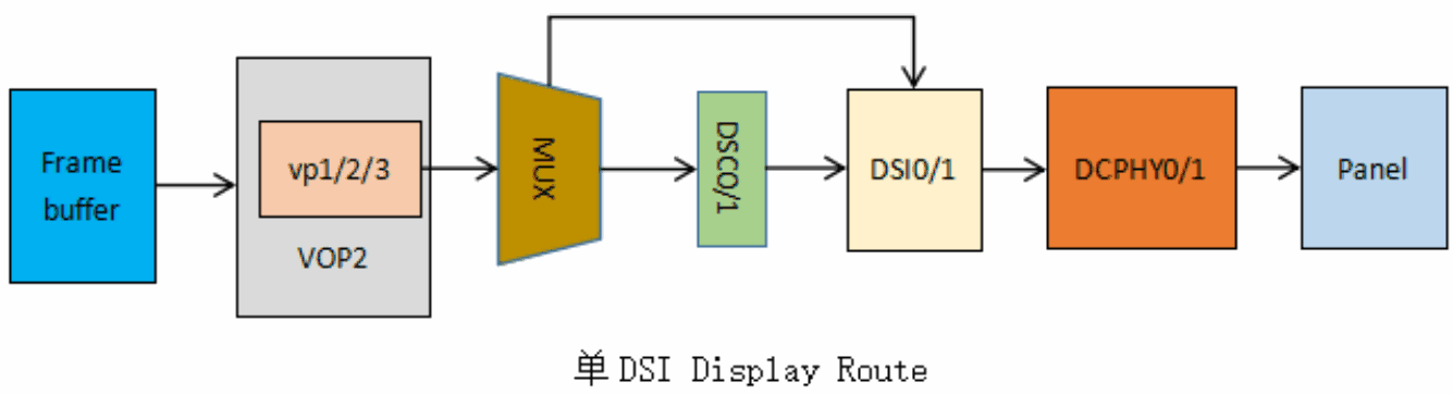
14.1.1 DSI0
&dsi0 {
    status = "okay";
    //rockchip,lane-rate = <1000>;
    //auto-calculation-mode;
    //disable-hold-mode;
    //support-psr;
    dsi0_panel: panel@0 {
        status = "okay";
        compatible = "simple-panel-dsi";
        ...
        ports {
            #address-cells = <1>;
            #size-cells = <0>;
            port@0 {
                reg = <0>;
                panel_in_dsi: endpoint {
                    remote-endpoint = <&dsi_out_panel>;
                };
            };
        };
    };
    ports {
        #address-cells = <1>;
        #size-cells = <0>;
        port@1 {
            reg = <1>;
            dsi_out_panel: endpoint {
                remote-endpoint = <&panel_in_dsi>;
            };
        };
    };
};
&mipi_dcphy0 {
    status = "okay";
};
14.1.2 DSI1
&dsi1 {
    status = "okay";
    //rockchip,lane-rate = <1000>;
    //auto-calculation-mode;
    //disable-hold-mode;
    //support-psr;
    dsi1_panel: panel@0 {
        status = "okay";
        compatible = "simple-panel-dsi";
        ...
        ports {
            #address-cells = <1>;
            #size-cells = <0>;
            port@0 {
                reg = <0>;
                panel_in_dsi1: endpoint {
                    remote-endpoint = <&dsi1_out_panel>;
                };
            };
        };
    };
    ports {
        #address-cells = <1>;
        #size-cells = <0>;
        port@1 {
            reg = <1>;
            dsi1_out_panel: endpoint {
                remote-endpoint = <&panel_in_dsi1>;
            };
        };
    };
};
&mipi_dcphy1 {
    status = "okay";
};
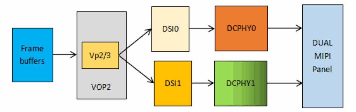
14.2 Dual-channel DSI
MODE1:
MODE2:
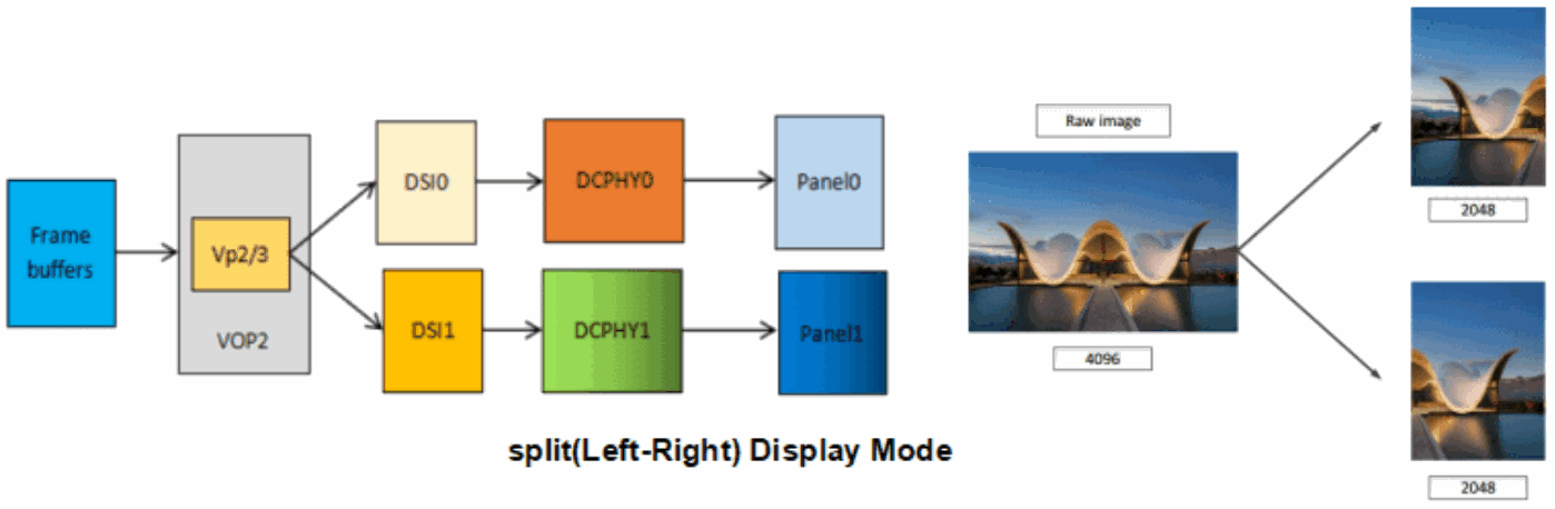
For dual-channel operation, note the highlighted properties: rockchip,dual-channel = <&dsi1> and dsi,lanes = <8>; for a DPHY panel. Set the lane count to 6 for a CPHY panel. The source’s complete DTS examples follow.
&dsi0 {
    status = "okay";
    rockchip,dual-channel = <&dsi1>;
    //auto-calculation-mode;
    //disable-hold-mode;
    //support-psr;
    dsi0_panel {
        status = "okay";
        compatible = "simple-panel-dsi";
        dsi,lanes = <8>;
        ...
        display-timings {
            native-mode = <&timing0>;
            timing0: timing0 {
                clock-frequency = <260000000>;
                hactive = <1440>;
                vactive = <2560>;
                hfront-porch = <150>;
                hsync-len = <30>;
                hback-porch = <60>;
                vfront-porch = <8>;
                vsync-len = <4>;
                vback-porch = <4>;
                hsync-active = <0>;
                vsync-active = <0>;
                de-active = <0>;
                pixelclk-active = <0>;
            };
        };
        ports {
            #address-cells = <1>;
            #size-cells = <0>;
            port@0 {
                reg = <0>;
                panel_in_dsi0: endpoint {
                    remote-endpoint = <&dsi0_out_panel>;
                };
            };
        };
    };
    ports {
        #address-cells = <1>;
        #size-cells = <0>;
        port@1 {
            reg = <1>;
            dsi0_out_panel: endpoint {
                remote-endpoint = <&panel_in_dsi0>;
            };
        };
    };
};
&dsi1 {
    status = "okay";
};
&mipi_dcphy0 {
    status = "okay";
};
&mipi_dcphy1 {
    status = "okay";
};
14.3 Dual-link DSI
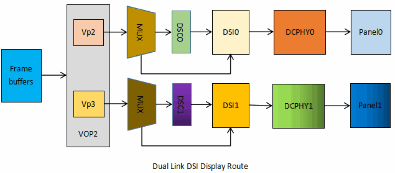
&dsi0 {
    status = "okay";
    //rockchip,lane-rate = <1000>;
    //auto-calculation-mode;
    //disable-hold-mode;
    //support-psr;
    dsi0_panel: panel@0 {
        status = "okay";
        compatible = "simple-panel-dsi";
        ...
        ports {
            #address-cells = <1>;
            #size-cells = <0>;
            port@0 {
                reg = <0>;
                panel_in_dsi: endpoint {
                    remote-endpoint = <&dsi_out_panel>;
                };
            };
        };
    };
    ports {
        #address-cells = <1>;
        #size-cells = <0>;
        port@1 {
            reg = <1>;
            dsi_out_panel: endpoint {
                remote-endpoint = <&panel_in_dsi>;
            };
        };
    };
};
&dsi1 {
    status = "okay";
    //rockchip,lane-rate = <1000>;
    //auto-calculation-mode;
    //disable-hold-mode;
    //support-psr;
    dsi1_panel: panel@0 {
        status = "okay";
        compatible = "simple-panel-dsi";
        ...
        ports {
            #address-cells = <1>;
            #size-cells = <0>;
            port@0 {
                reg = <0>;
                panel_in_dsi1: endpoint {
                    remote-endpoint = <&dsi1_out_panel>;
                };
            };
        };
    };
    ports {
        #address-cells = <1>;
        #size-cells = <0>;
        port@1 {
            reg = <1>;
            dsi1_out_panel: endpoint {
                remote-endpoint = <&panel_in_dsi1>;
            };
        };
    };
};
&mipi_dcphy0 {
    status = "okay";
};
&mipi_dcphy1 {
    status = "okay";
};
14.4 DSI application scenarios
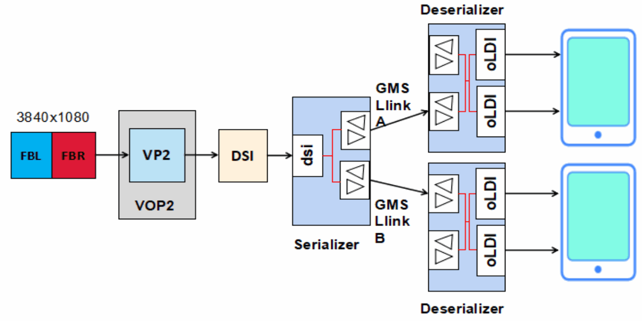
14.4.1 DSI + SerDer design
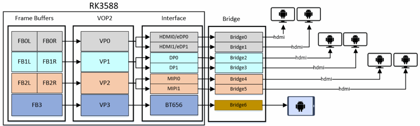
14.4.2 Multi-display composition
15. DC-PHY
The default configuration uses D-PHY. As explained in the panel configuration section, the following setting selects C-PHY:
dsi0_panel: panel@0 {
    ...
    phy-c-option;
    ...
};
15.1 D-PHY
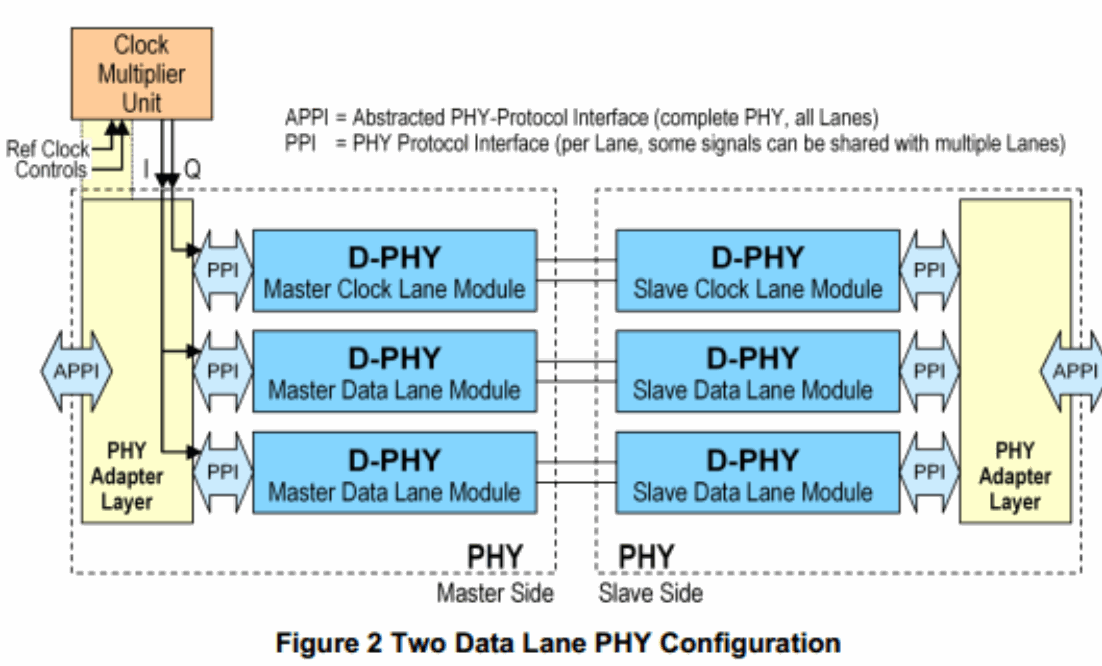
1. Up to 4.5 Gbps per lane in D-PHY;
2. A D-PHY port has up to 4 lanes, each consisting of two differential wires;
3. D denotes the Roman numeral 500. Initially D-PHY had a maximum data rate of 1G (DDR) and a corresponding 500MHz clock. Modern D-PHY rates exceed those values, so D no longer has that significance.
15.2 C-PHY
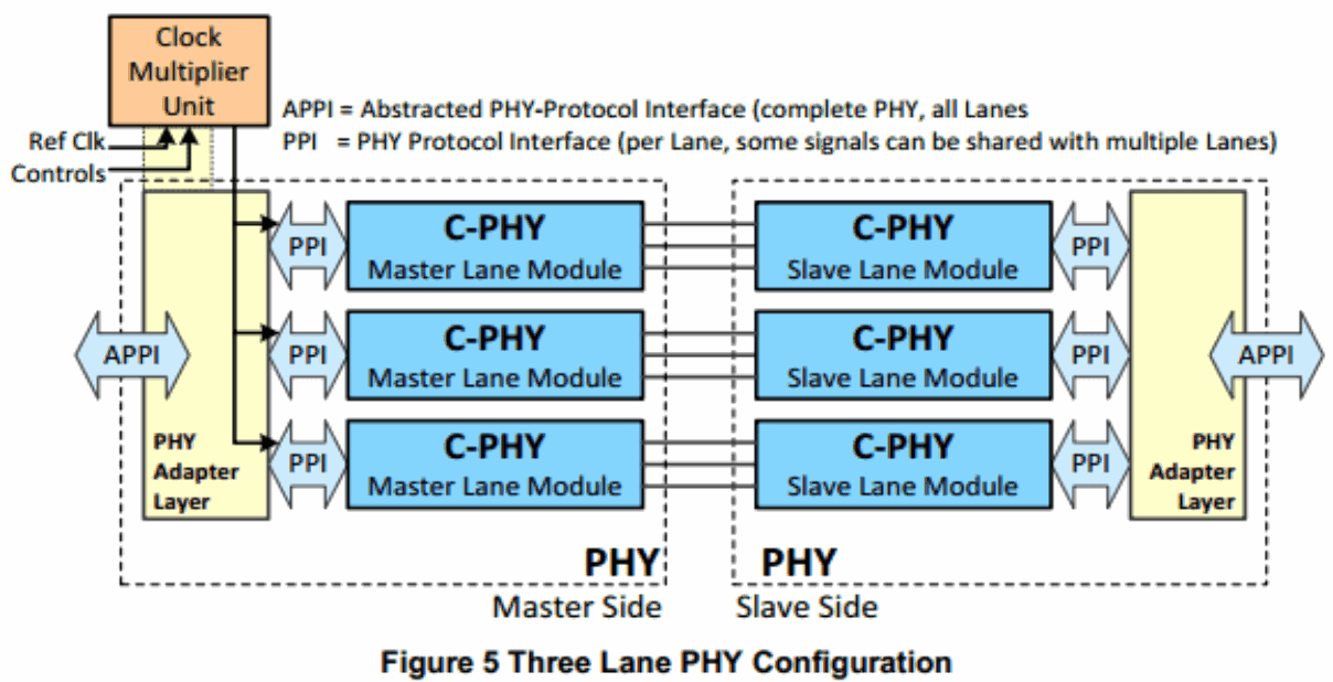
1. Up to 2.0 Gsps per trio in C-PHY;
2. A C-PHY port has up to 3 lanes, each consisting of a three-wire trio (the source spells this “tree-wire-trios”);
3. C-PHY has no separate clock lane; its clock is embedded in the communication timing;
4. C means Channel-limited: the number of channels is limited to 3. C-PHY has 3 lanes, each using three-wire transmission.
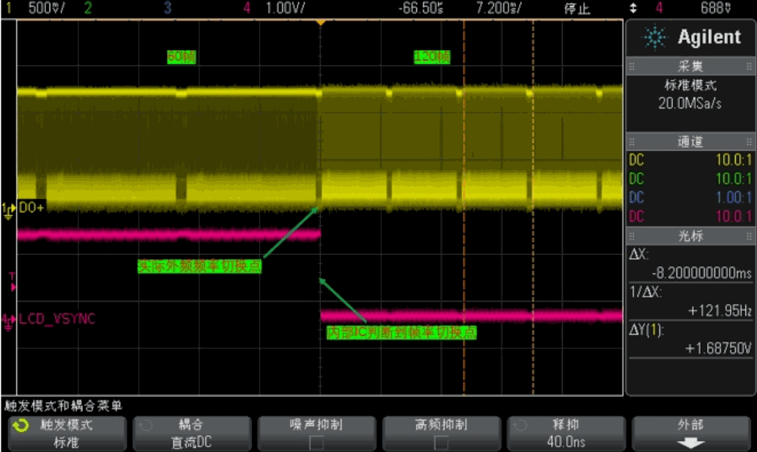
16. Dynamic frame-rate switching
MIPI DSI supports dynamic, seamless frame-rate switching, for example between 120fps and 60fps. Refer to Rockchip_RK3588_Developer_Guide_Vsync_Adjust_CN for details.
17. PSR
When MIPI DSI operates in COMMAND mode and the panel contains GRAM, the host DSI output may be disabled while displaying a static frame to reduce power consumption. The panel continues refreshing that frame from GRAM. Whenever a new frame changes any displayed content, the host must enable output and refresh the panel GRAM to update the display.
18. Protocol analysis
18.1 DSI layer definitions
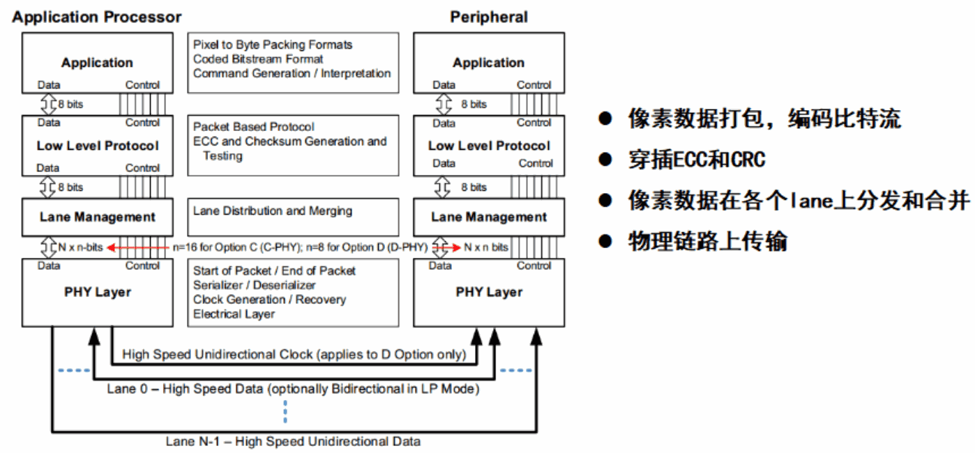
18.2 D Option
18.2.1 Lane states and line levels
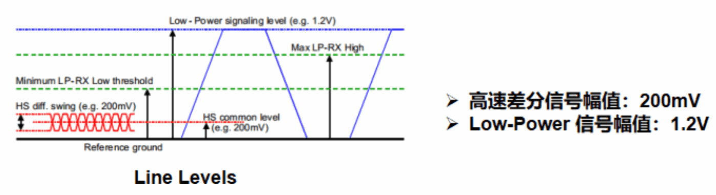
The following table lists all lane states that may occur during normal DPHY operation.
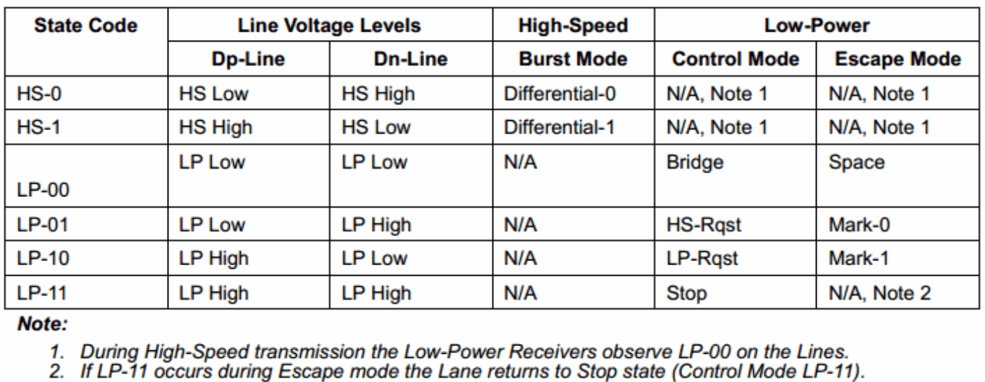
Editable transcription of the original figure:
| State | Dp-Line | Dn-Line | HS Burst | LP Control | LP Escape |
|---|---|---|---|---|---|
| HS-0 | HS Low | HS High | Differential-0 | N/A (1) | N/A (1) |
| HS-1 | HS High | HS Low | Differential-1 | N/A (1) | N/A (1) |
| LP-00 | LP Low | LP Low | N/A | Bridge | Space |
| LP-01 | LP Low | LP High | N/A | HS-Rqst | Mark-0 |
| LP-10 | LP High | LP Low | N/A | LP-Rqst | Mark-1 |
| LP-11 | LP High | LP High | N/A | Stop | N/A (2) |
(1) During high-speed transmission the low-power receivers observe LP-00. (2) LP-11 during Escape Mode returns the line to Stop (Control Mode LP-11).
18.2.2 Global operation flow diagram
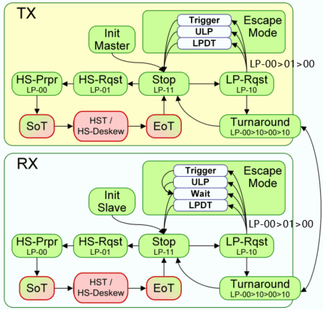
A DSI data lane may enter the following three modes:
1. Escape Mode (only Dp0/Dn0 operates in this mode);
2. Bus Turnaround Request (only Dp0/Dn0 operates in this mode);
3. High-Speed Data Transmission.
These modes and their entry sequences are defined below.

Editable transcription of the original figure:
| Mode | Entry | Exit |
|---|---|---|
| Escape Mode | LP-11 → LP-10 → LP-00 → LP-01 → LP-00 | LP-00 → LP-10 → LP-11 (Mark-1) |
| High-Speed Data Transmission | LP-11 → LP-01 → LP-00 → HS-0 | (HS-0 or HS-1) → LP-11 |
| Bus Turnaround Request | LP-11 → LP-10 → LP-00 → LP-10 → LP-00 | Hi-Z |
18.2.2.1 Escape modes
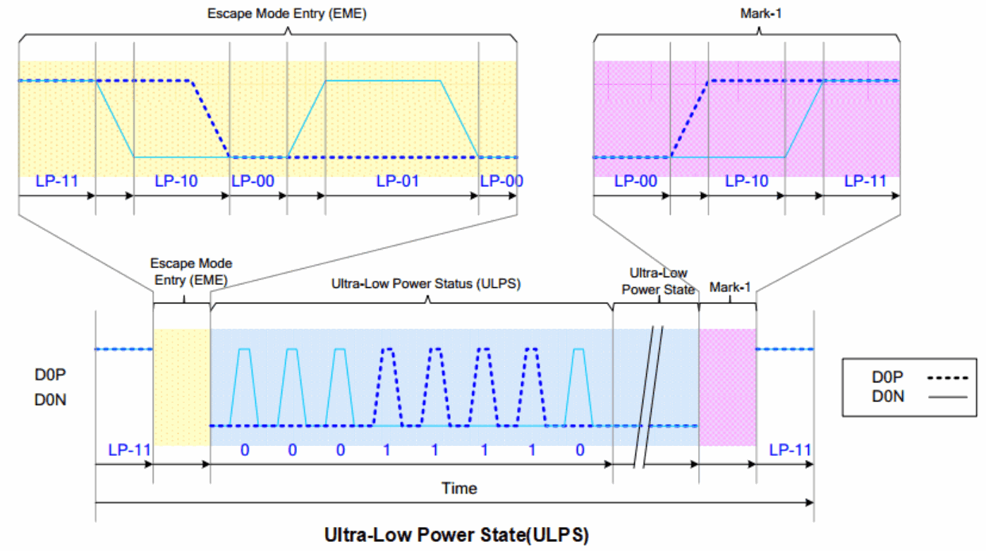
While data lanes operate in LP mode, data lane 0 is used for Escape Mode. It enters Escape Mode through LP-11->LP-10->LP-00->LP-01->LP-00 and exits through LP-00->LP-10->LP-11.
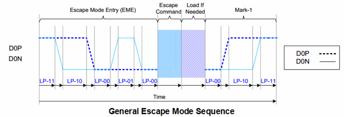
18.2.2.1.1 Escape commands
After the data lane enters Escape Mode, the transmitter sends an 8-bit Escape Command indicating the requested action. The commands are listed below.
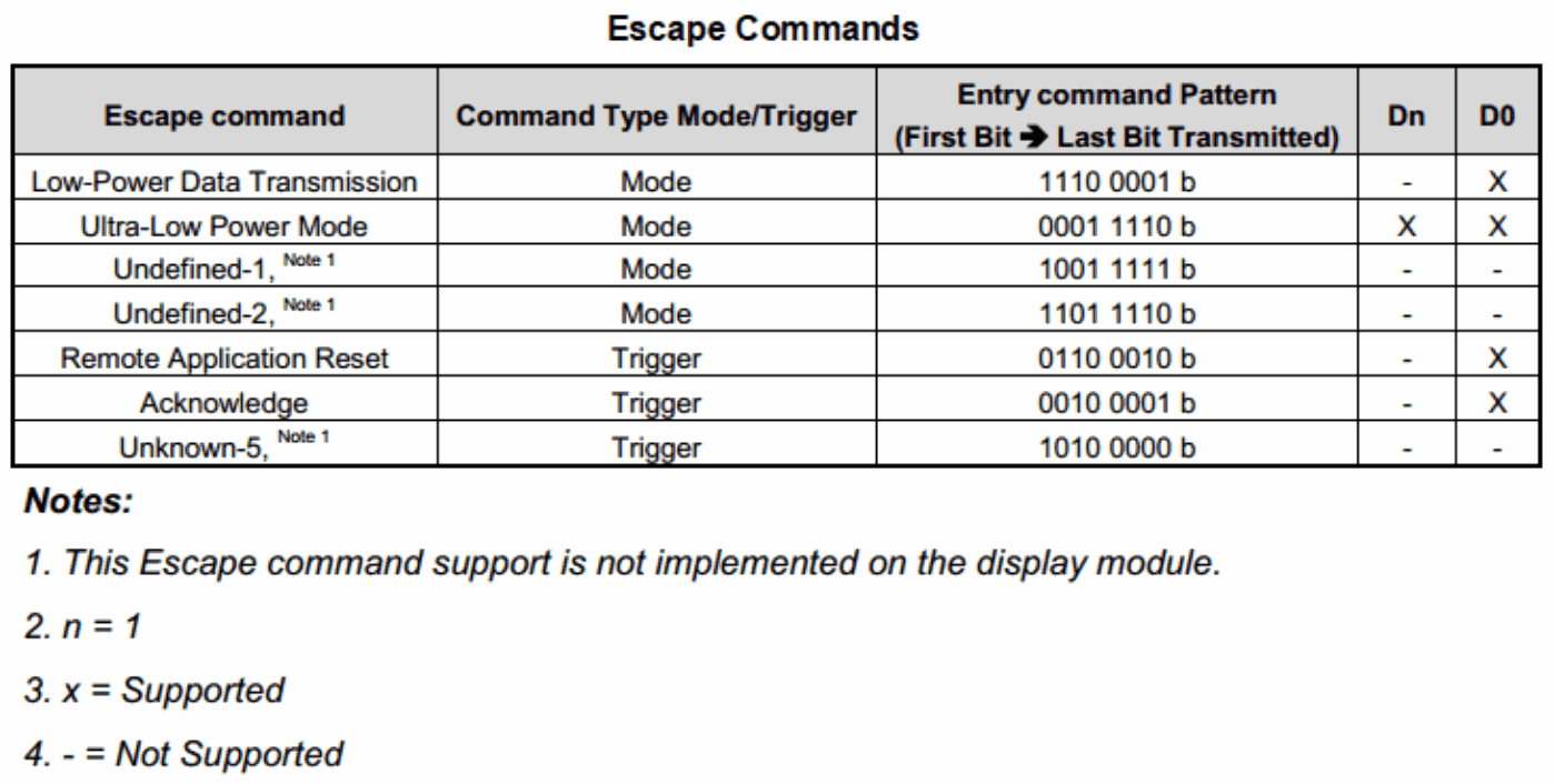
Editable transcription of the original figure:
| Escape command | Type | First → last bit transmitted | Dn | D0 |
|---|---|---|---|---|
| Low-Power Data Transmission | Mode | 1110 0001 b | - | X |
| Ultra-Low Power Mode | Mode | 0001 1110 b | X | X |
| Undefined-1 (1) | Mode | 1001 1111 b | - | - |
| Undefined-2 (1) | Mode | 1101 1110 b | - | - |
| Remote Application Reset | Trigger | 0110 0010 b | - | X |
| Acknowledge | Trigger | 0010 0001 b | - | X |
| Unknown-5 (1) | Trigger | 1010 0000 b | - | - |
(1) This Escape command is not implemented on the display module. n=1; X=supported; -=not supported.
18.2.2.1.2 LPDT
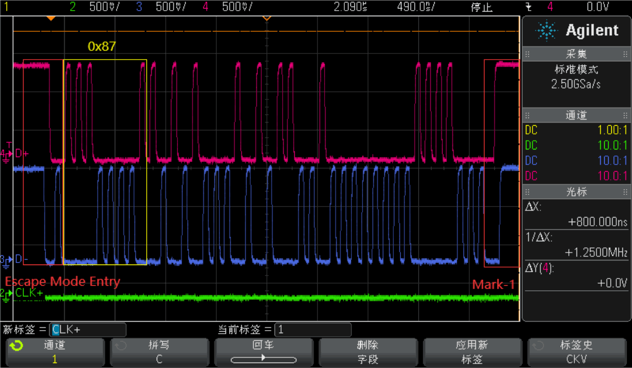
After the lane enters Escape Mode and sends the Low-Power Data Transmission (LPDT) sequence to the display module, the SoC MIPI DSI TX can send data in LPDT mode. This is generally how initialization sequences are downloaded to MIPI display modules.
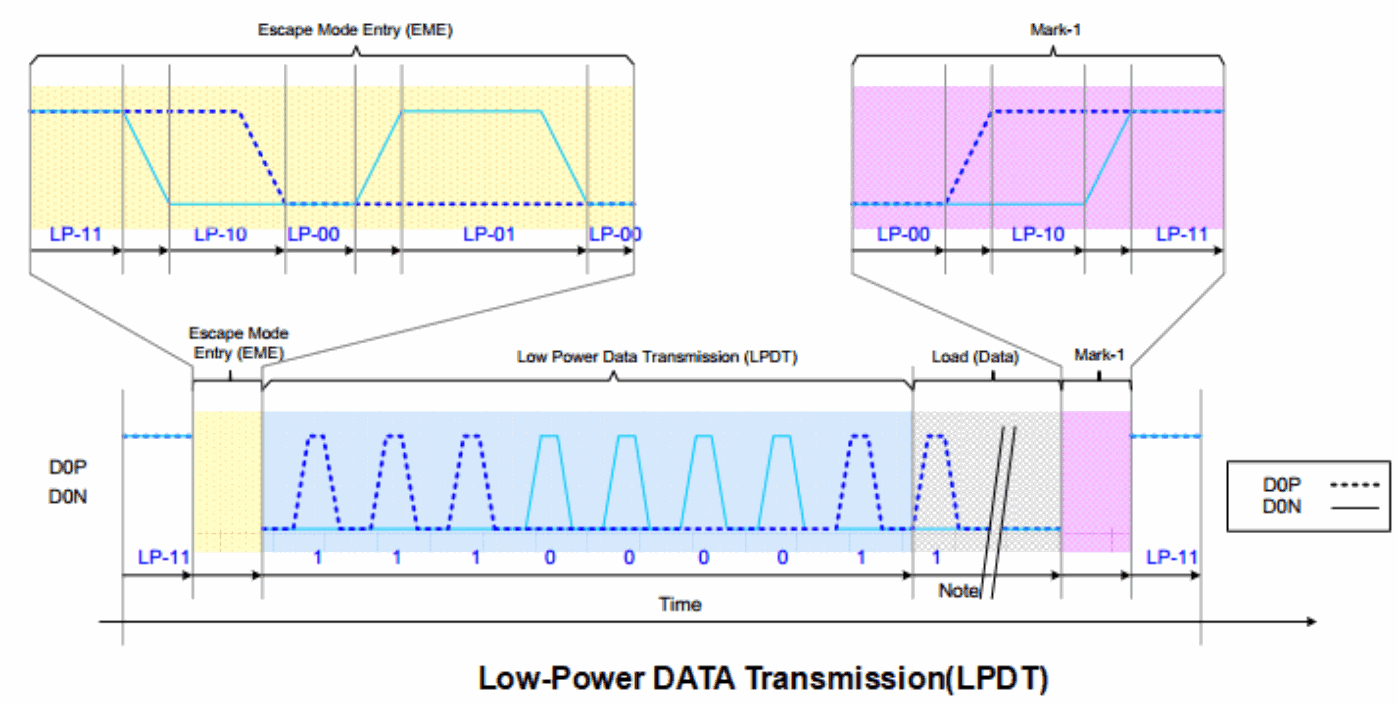
The following oscilloscope capture shows LPDT.
18.2.2.1.3 ULPS
18.2.2.2 HSDT
When the DPHY clock lane operates in high-speed clock mode, the display module can enter high-speed data transmission. All data lanes enter this mode simultaneously, but need not leave it simultaneously. The entry sequence is:
LP-11 -> LP-01 -> LP-00 -> HS-0 -> SoT(0001_1101).
1. Start: LP-11
2. HS-Request: LP-01
3. HS-Settle: LP-00 -> HS-0 (RX: Lane Termination Enable)
4. Rx Synchronization: SoT(0001_1101)
5. End: High-Speed Data Transmission (HSDT) - Ready to receive High-Speed Data Load
To exit high-speed data transmission, invert the differential state immediately after the last payload datum and hold that state for Ths-trail.
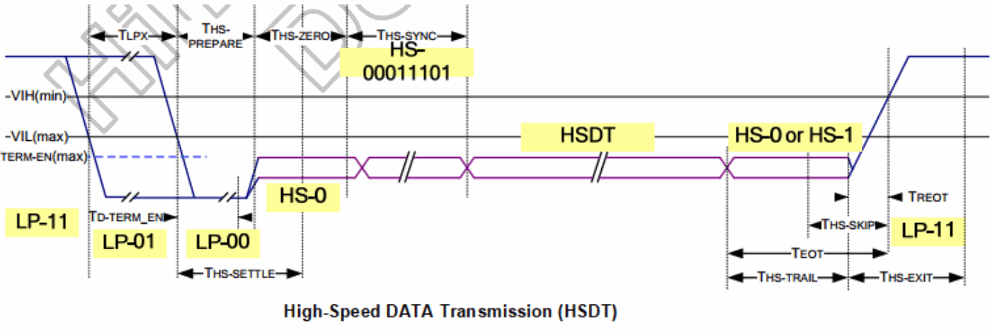
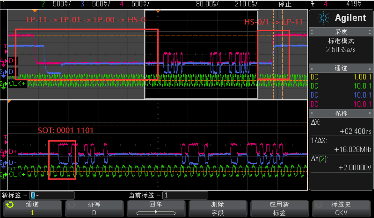
The following oscilloscope capture shows HSDT.
18.2.2.3 BTA
To obtain information from the display module, the first SoC DPHY data lane performs bus turnaround. The procedure is shown below.
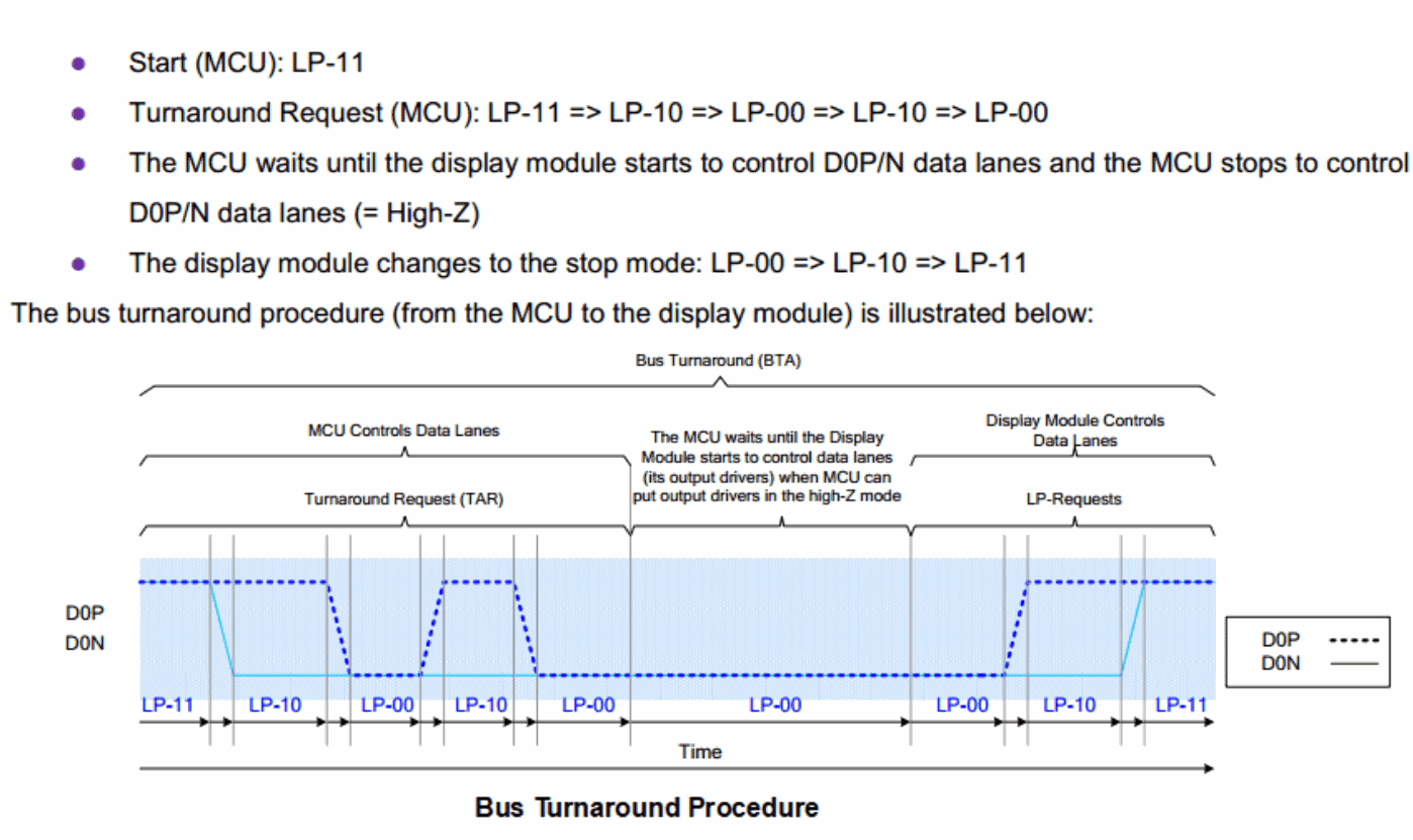
Editable transcription of the original figure:
BTA procedure: the MCU starts at LP-11 and requests turnaround with LP-11 → LP-10 → LP-00 → LP-10 → LP-00. It waits for the module to drive D0P/N, then stops driving those lanes (High-Z). The module enters Stop through LP-00 → LP-10 → LP-11.
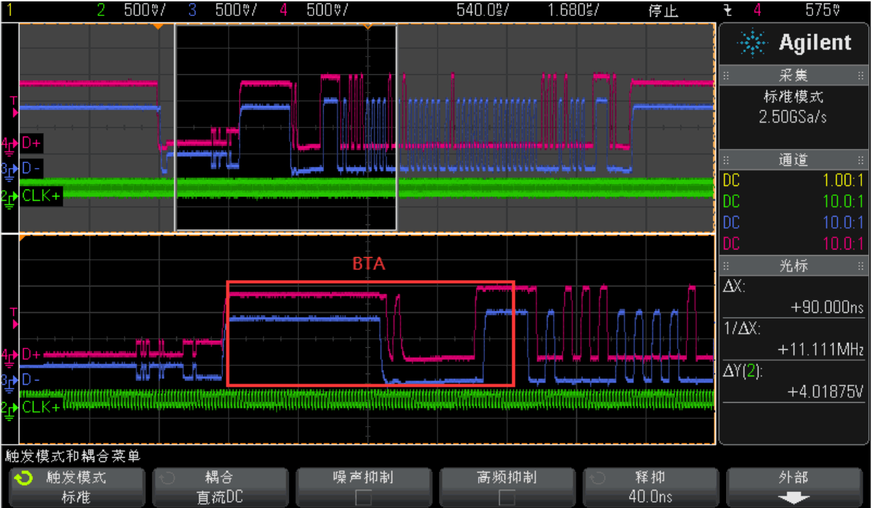
The following oscilloscope capture shows BTA while reading back from the display module during HSDT.
18.2.3 Endian policy
In both LP and HS data transmission, data is packaged into long and short packets and sent to the display module.
18.2.3.1 SPa
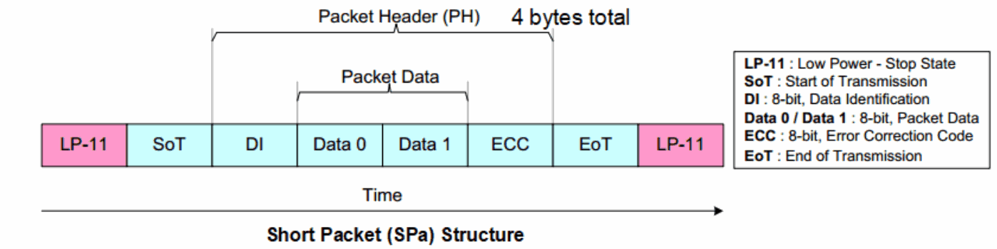
Example:
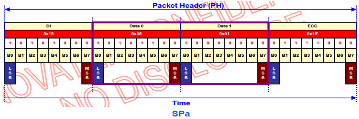
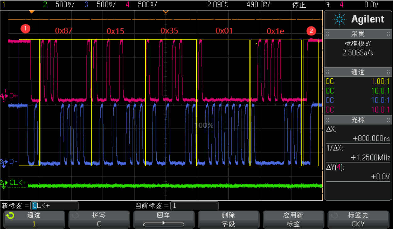
18.2.3.1.1 LPDT-SPa
The following oscilloscope capture shows the above SPa sent to the display module in LPDT mode.
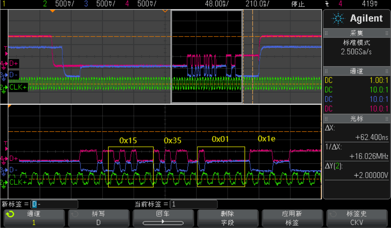
18.2.3.1.2 HSDT-SPa
The following oscilloscope capture shows the above SPa sent to the display module in HSDT mode.
18.2.3.2 LPa
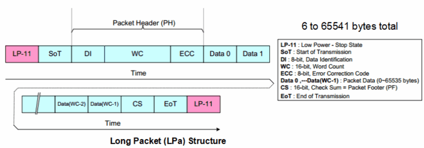
Example:
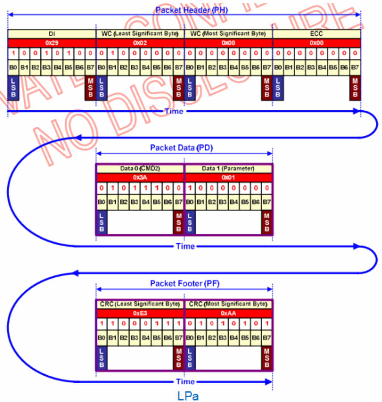
18.2.3.2.1 LPDT-LPa
The following oscilloscope capture shows the above LPa sent to the display module in LPDT mode.
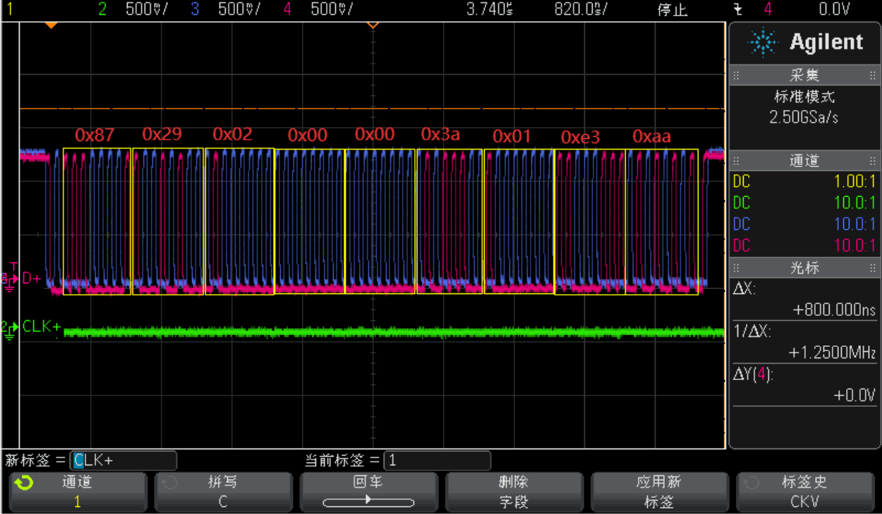
18.2.3.2.2 HSDT-LPa
The following oscilloscope capture shows the above LPa sent to the display module in HSDT mode.
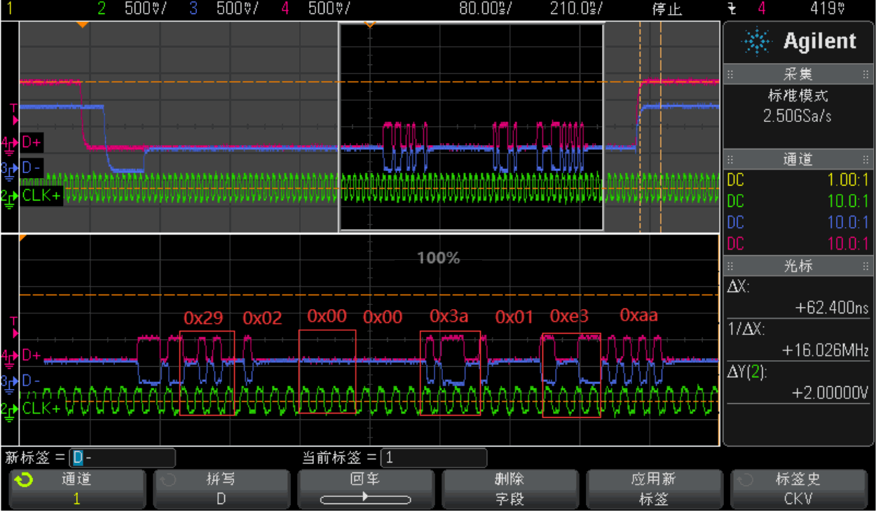
18.2.3.3 DI
Both SPa and LPa contain Data Identification (DI), which determines whether a packet is long or short. DI belongs to the packet header and consists of two parts:
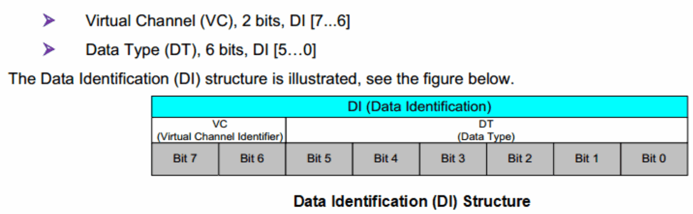
Editable transcription of the original figure:
| DI field | Bits | Width |
|---|---|---|
| VC (Virtual Channel) | DI[7:6] | 2 |
| DT (Data Type) | DI[5:0] | 6 |
Most data types currently defined by the MIPI protocol are listed below.
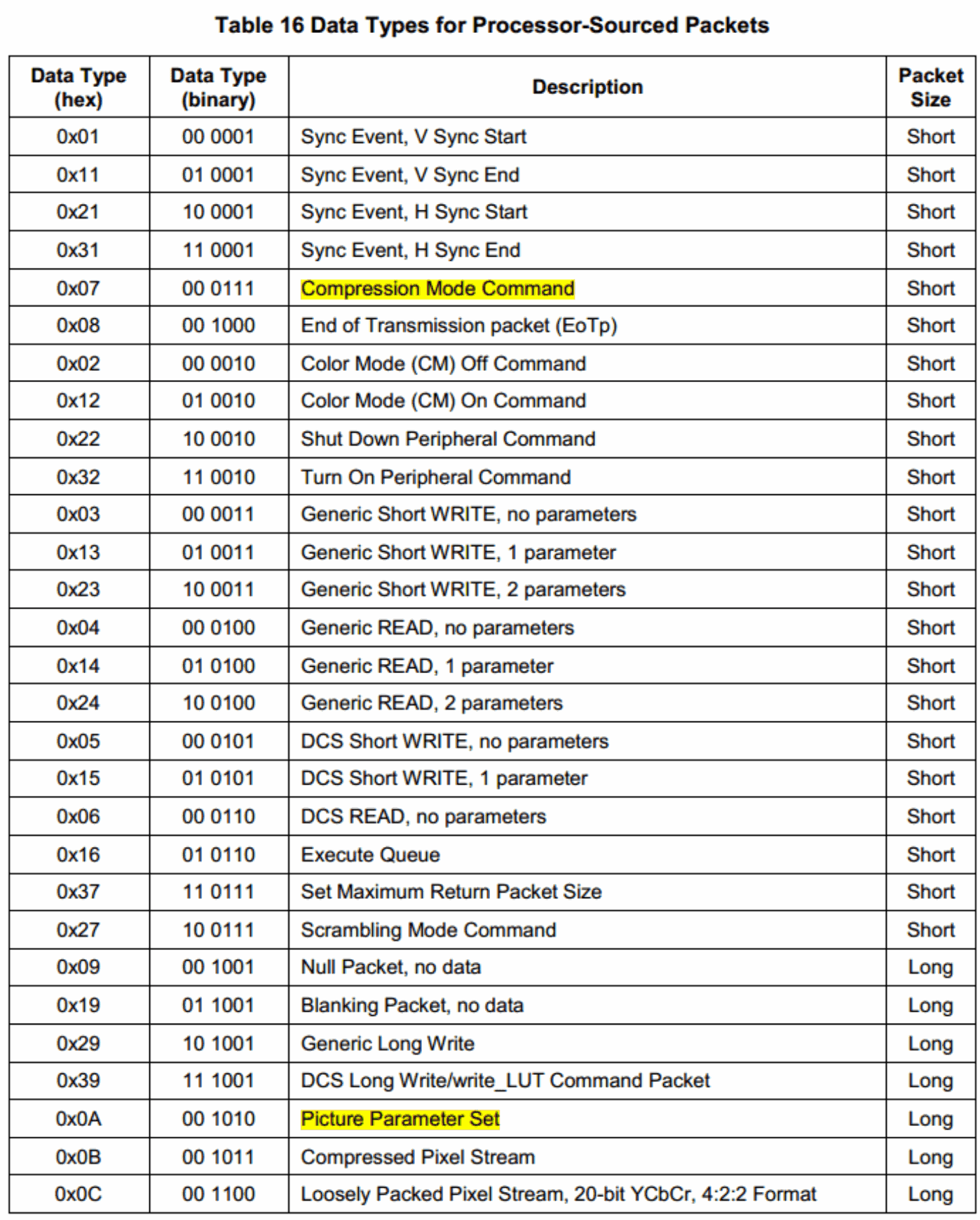
Editable transcription of the original figure:
| Data type (hex) | Binary | Description | Packet size |
|---|---|---|---|
| 0x01 | 00 0001 | Sync event: V Sync start | Short |
| 0x11 | 01 0001 | Sync event: V Sync end | Short |
| 0x21 | 10 0001 | Sync event: H Sync start | Short |
| 0x31 | 11 0001 | Sync event: H Sync end | Short |
| 0x07 | 00 0111 | Compression Mode Command | Short |
| 0x08 | 00 1000 | End of Transmission packet (EoTp) | Short |
| 0x02 | 00 0010 | Color Mode (CM) Off Command | Short |
| 0x12 | 01 0010 | Color Mode (CM) On Command | Short |
| 0x22 | 10 0010 | Shut Down Peripheral Command | Short |
| 0x32 | 11 0010 | Turn On Peripheral Command | Short |
| 0x03 | 00 0011 | Generic Short WRITE, no parameters | Short |
| 0x13 | 01 0011 | Generic Short WRITE, 1 parameter | Short |
| 0x23 | 10 0011 | Generic Short WRITE, 2 parameters | Short |
| 0x04 | 00 0100 | Generic READ, no parameters | Short |
| 0x14 | 01 0100 | Generic READ, 1 parameter | Short |
| 0x24 | 10 0100 | Generic READ, 2 parameters | Short |
| 0x05 | 00 0101 | DCS Short WRITE, no parameters | Short |
| 0x15 | 01 0101 | DCS Short WRITE, 1 parameter | Short |
| 0x06 | 00 0110 | DCS READ, no parameters | Short |
| 0x16 | 01 0110 | Execute Queue | Short |
| 0x37 | 11 0111 | Set Maximum Return Packet Size | Short |
| 0x27 | 10 0111 | Scrambling Mode Command | Short |
| 0x09 | 00 1001 | Null Packet, no data | Long |
| 0x19 | 01 1001 | Blanking Packet, no data | Long |
| 0x29 | 10 1001 | Generic Long Write | Long |
| 0x39 | 11 1001 | DCS Long Write/write_LUT Command Packet | Long |
| 0x0A | 00 1010 | Picture Parameter Set | Long |
| 0x0B | 00 1011 | Compressed Pixel Stream | Long |
| 0x0C | 00 1100 | Loosely Packed Pixel Stream, 20-bit YCbCr, 4:2:2 Format | Long |
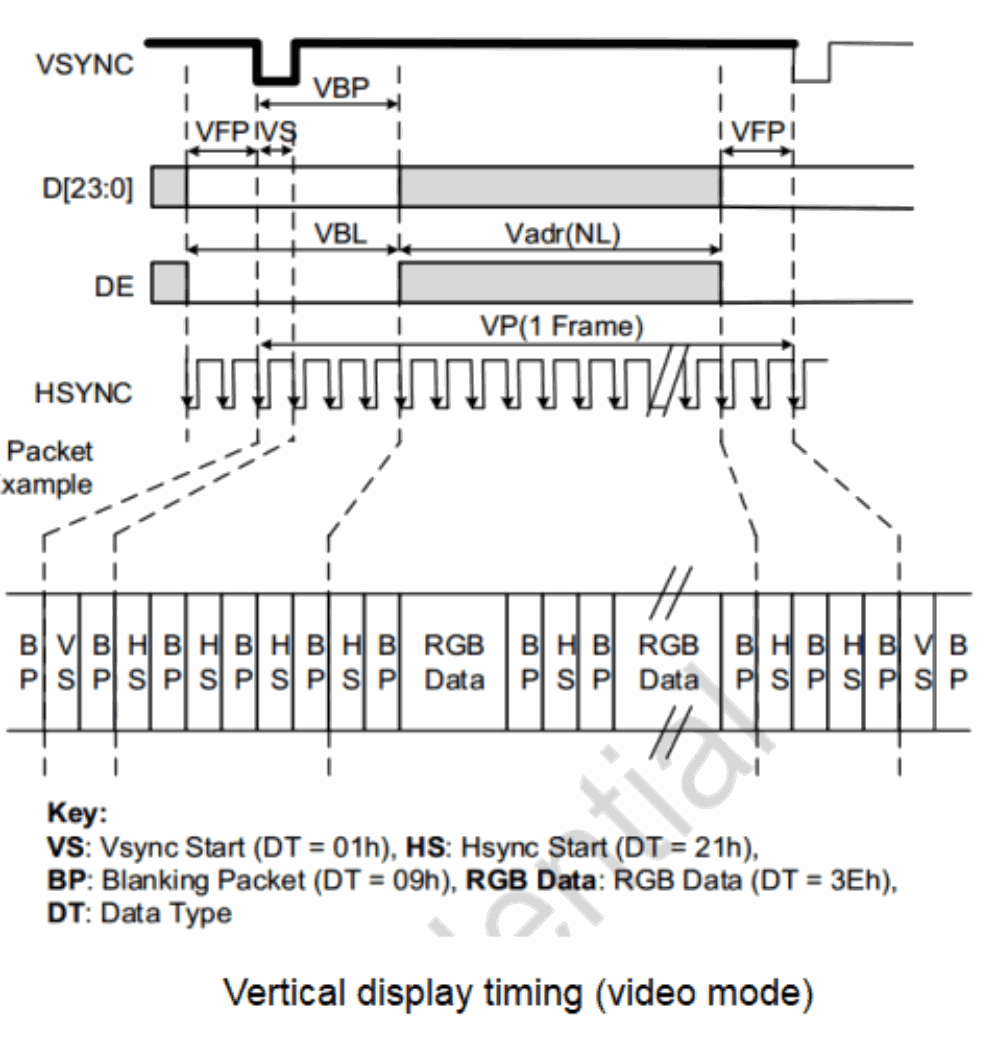
18.2.4 Video-mode interface timing
18.2.4.1 Vertical display timing (video mode)
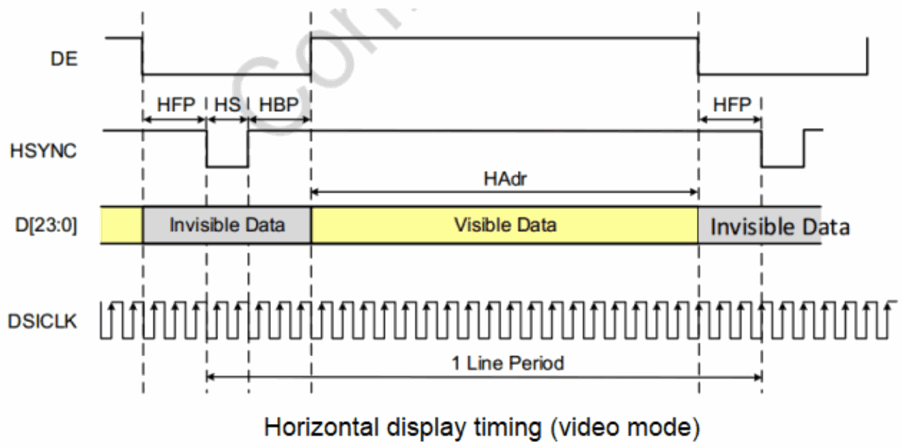
18.2.4.2 Horizontal display timing (video mode)
18.2.4.3 Non-burst mode with sync pulses
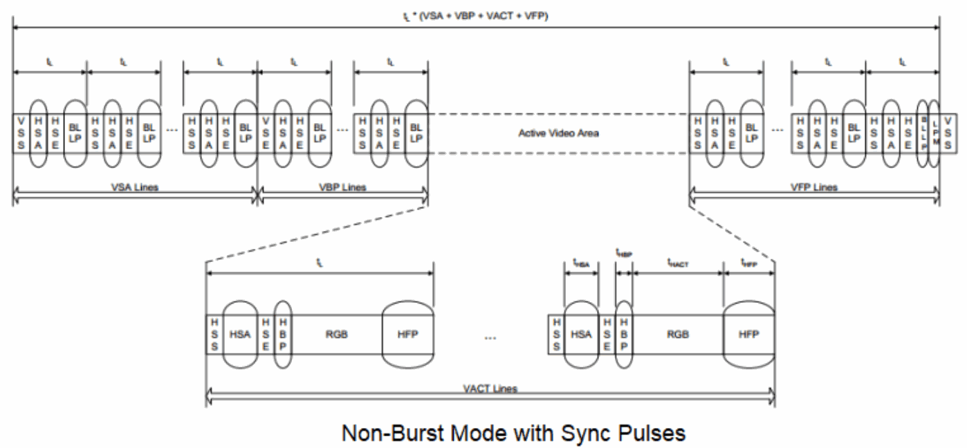
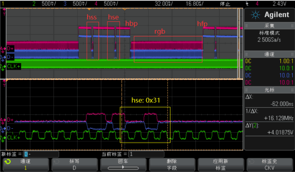
The following oscilloscope capture shows Non Burst Sync Pulse operation.
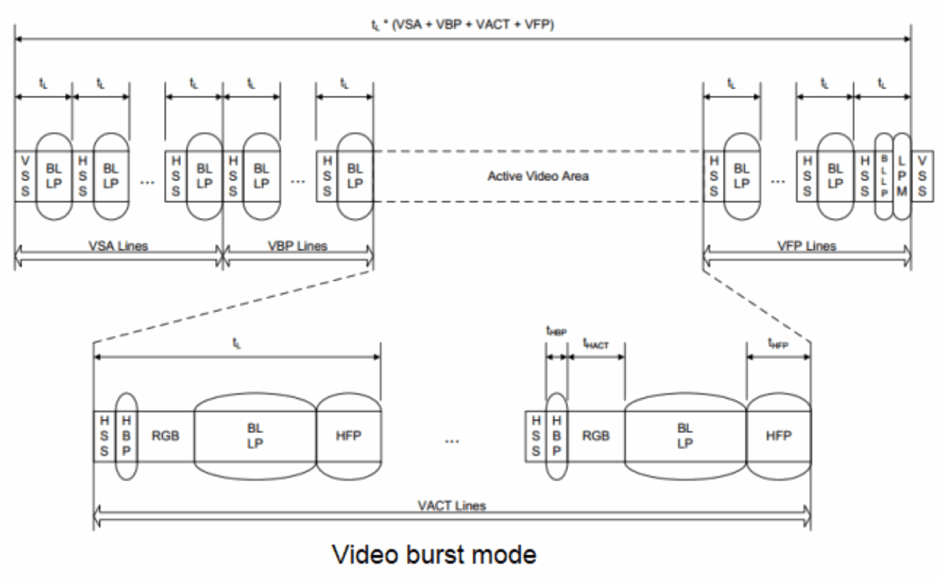
18.2.4.4 Burst mode
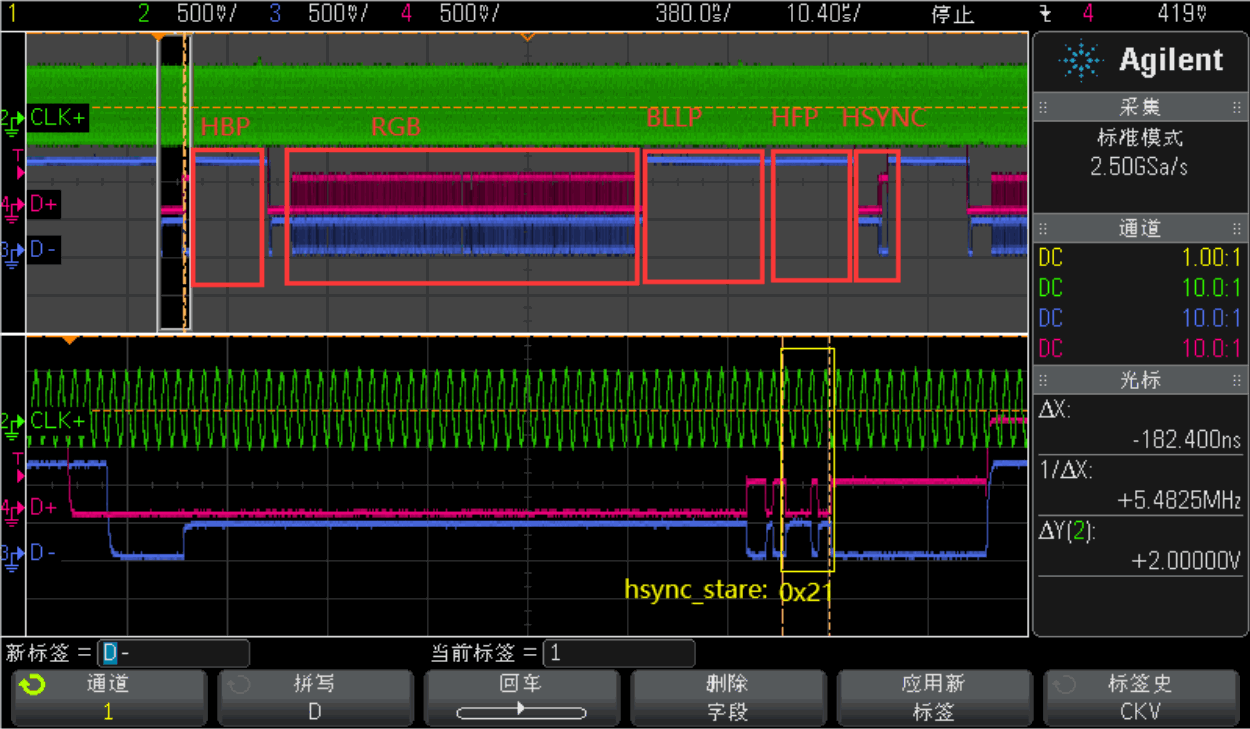
The following oscilloscope capture shows Video Burst operation.
19. Common issues
19.1 Inspecting VOP timing and connector information
console:/ # cat /d/dri/0/summary
Video Port0: DISABLED
Video Port1: DISABLED
Video Port2: DISABLED
Video Port3: ACTIVE
    Connector: DSI-2
        bus_format[100a]: RGB888_1X24
        overlay_mode[0] output_mode[0] color_space[0]
    Display mode: 1080x1920p60
        clk[132000] real_clk[132000] type[48] flag[a]
        H: 1080 1095 1099 1129
        V: 1920 1935 1937 1952
    Cluster3-win0: ACTIVE
        win_id: 6
        format: AB24 little-endian (0x34324241) SDR[0] color_space[0] glb_alpha[0xff]
        rotate: xmirror: 0 ymirror: 0 rotate_90: 0 rotate_270: 0
        csc: y2r[0] r2y[0] csc mode[0]
        zpos: 0
        src: pos[0, 0] rect[1080 x 1920]
        dst: pos[0, 0] rect[1080 x 1920]
        buf[0]: addr: 0x000000000376e000 pitch: 4352 offset: 0
19.2 Inspecting the DSI2 clock tree
When MIPI operates without DSC, its interface transfers 4 pixels per clock cycle. The clocks must satisfy:
video_timing_pixel_rate / 4 = mipi_pixel_clock × K = dclk_out × K = dclk_core
When MIPI operates with DSC, the clocks must satisfy:
mipi_pixel_clock = cds_clk / 2
Note: K = 1 by default; K = 2 for dual-channel MIPI display mode.
console:/ # cat /d/clk/clk_summary | grep vop
    clk_vop_pmu 0 0 0 24000000 0 0 50000
          dclk_vop3 1 2 0 33000000 0 0 50000
          dclk_vop1_src 0 1 0 594000000 0 0 50000
             dclk_vop1 0 1 0 594000000 0 0 50000
          dclk_vop0_src 0 1 0 594000000 0 0 50000
             dclk_vop0 0 1 0 594000000 0 0 50000
             aclk_vop_low_root 1 1 0 396000000 0 0 50000
             hclk_vop_root 2 4 0 198000000 0 0 50000
                hclk_vop 1 3 0 198000000 0 0 50000
          aclk_vop_root 1 1 0 500000000 0 0 50000
             aclk_vop_doby 0 0 0 500000000 0 0 50000
             aclk_vop_sub_src 1 1 0 500000000 0 0 50000
                aclk_vop 1 4 0 500000000 0 0 50000
             pclk_vop_root 3 5 0 100000000 0 0 50000
          dclk_vop2_src 1 1 0 148500000 0 0 50000
             dclk_vop2 1 2 0 148500000 0 0 50000
console:/ # cat /d/clk/clk_summary | grep dsi
                pclk_dsihost1 1 2 0 100000000 0 0 50000
                pclk_dsihost0 1 2 0 100000000 0 0 50000
    clk_dsihost1 1 2 0 351000000 0 0 50000
    clk_dsihost0 1 2 0 351000000 0 0 50000
console:/ # cat /d/clk/clk_summary | grep mipi
          mipi1_clk_src 0 0 0 33000000 0 0 50000
             mipi1_pixclk 0 0 0 33000000 0 0 50000
          mipi0_clk_src 0 0 0 148500000 0 0 50000
             mipi0_pixclk 0 0 0 148500000 0 0 50000
    clk_usbdpphy_mipidcpphy_ref 5 5 0 24000000 0 0 50000
    clk_mipi_camaraout_m4 0 0 0 24000000 0 0 50000
    clk_mipi_camaraout_m3 0 0 0 24000000 0 0 50000
    clk_mipi_camaraout_m2 0 0 0 24000000 0 0 50000
    clk_mipi_camaraout_m0 0 0 0 24000000 0 0 50000
          clk_mipi_camaraout_m1 0 0 0 37125000 0 0 50000
                pclk_mipi_dcphy1 1 1 0 100000000 0 0 50000
                pclk_mipi_dcphy0 1 1 0 100000000 0 0 50000
console:/ #
19.3 Inspecting the configured DSI lane rate
There are two ways to specify the DSI lane rate. One is automatic driver calculation:
dmesg | grep dsi
[ 77.369812] dw-mipi-dsi2 fde20000.dsi: [drm:dw_mipi_dsi2_encoder_enable] final DSI-Link
bandwidth: 879 x 4 Mbps
The other is to specify it manually with this property:
&dsi0 {
    ...
    rockchip,lane-rate = <1000>;
    ...
}
19.4 MIPI DSI2 HOST has no internal color-bar function; use VOP2 color bars with these commands
Select the appropriate command for the display route:
19.4.1 RK3588
vp0:
io -4 0xfdd90c08 0x1 && io -4 0xfdd90000 0xffffffff
vp1:
io -4 0xfdd90d08 0x1 && io -4 0xfdd90000 0xffffffff
vp2:
io -4 0xfdd90e08 0x1 && io -4 0xfdd90000 0xffffffff
vp3:
io -4 0xfdd90f08 0x1 && io -4 0xfdd90000 0xffffffff
19.4.2 RK3576
vp0:
io -4 0x27d00c08 0x1 && io -4 0x27d00000 0xffffffff
vp1:
io -4 0x27d00d08 0x1 && io -4 0x27d00000 0xffffffff
vp2:
io -4 0x27d00e08 0x1 && io -4 0x27d00000 0xffffffff
19.5 Checking MIPI DSI2–panel communication when display output is abnormal
U-Boot:
--- a/drivers/video/drm/rockchip_panel.c
+++ b/drivers/video/drm/rockchip_panel.c
@@ -260,6 +260,7 @@ static void panel_simple_prepare(struct rockchip_panel *panel)
    struct rockchip_panel_priv *priv = dev_get_priv(panel->dev);
    struct mipi_dsi_device *dsi = dev_get_parent_platdata(panel->dev);
    int ret;
+ u8 mode;
    if (priv->prepared)
        return;
@@ -285,6 +286,8 @@ static void panel_simple_prepare(struct rockchip_panel *panel)
    if (plat->delay.init)
        mdelay(plat->delay.init);
+ mipi_dsi_dcs_get_power_mode(dsi, &mode);
+ printf("===>mode: 0x%x\n", mode);
    if (plat->on_cmds) {
        if (priv->cmd_type == CMD_TYPE_SPI)
            ret = rockchip_panel_send_spi_cmds(panel->state,
@@ -298,6 +301,8 @@ static void panel_simple_prepare(struct rockchip_panel *panel)
            printf("failed to send on cmds: %d\n", ret);
    }
+ mipi_dsi_dcs_get_power_mode(dsi, &mode);
+ printf("===>mode: 0x%x\n", mode);
    priv->prepared = true;
 }
Kernel:
--- a/drivers/gpu/drm/panel/panel-simple.c
+++ b/drivers/gpu/drm/panel/panel-simple.c
@@ -506,6 +506,7 @@ static int panel_simple_prepare(struct drm_panel *panel)
    unsigned int delay;
    int err;
    int hpd_asserted;
+ u8 mode;
    if (p->prepared)
        return 0;
@@ -554,6 +555,8 @@ static int panel_simple_prepare(struct drm_panel *panel)
        }
    }
+ mipi_dsi_dcs_get_power_mode(p->dsi, &mode);
+ printk("===>mode: 0x%x\n", mode);
    if (p->desc->init_seq)
        if (p->dsi)
            panel_simple_xfer_dsi_cmd_seq(p, p->desc->init_seq);
@@ -561,6 +564,9 @@ static int panel_simple_prepare(struct drm_panel *panel)
    if (p->desc->delay.init)
        msleep(p->desc->delay.init);
+ mipi_dsi_dcs_get_power_mode(p->dsi, &mode);
+ printk("===>mode: 0x%x\n", mode);
+
    p->prepared = true;
    return 0;
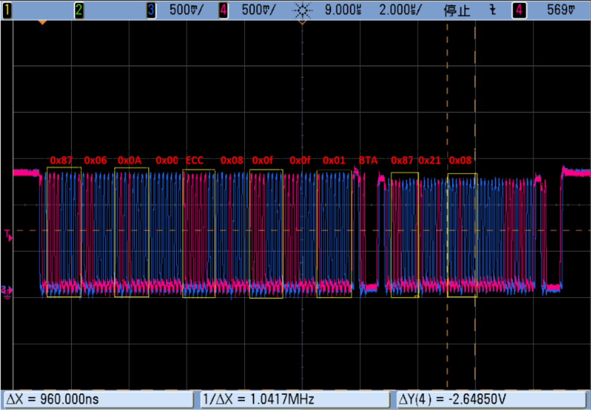
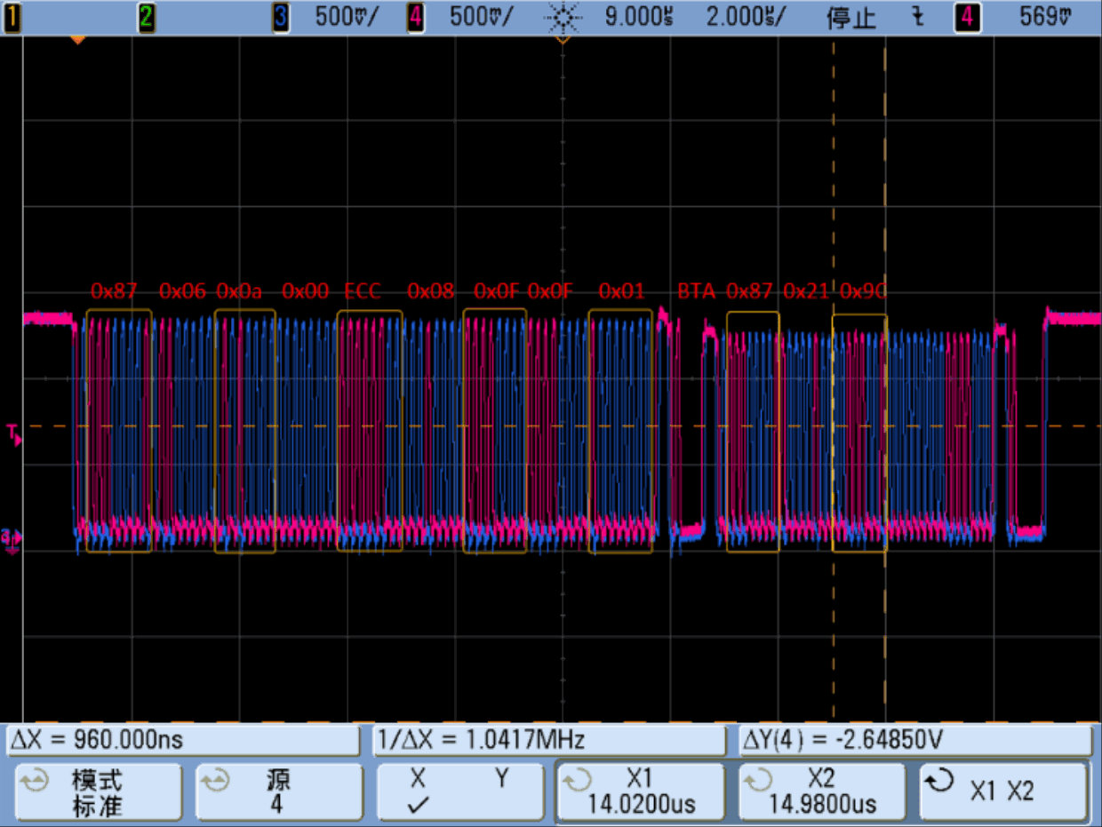
Normal communication produces the following messages. Otherwise, check panel timing and ensure the panel is ready:
===> mode: 0x8
===> mode: 0x9c
19.5.1 Two get_power_mode readback waveforms
19.5.1.1 Normal panel response 0x08 (0x11 and 0x29 not sent)
19.5.1.2 Normal panel response 0x9c (0x11 and 0x29 already sent)
19.6 DRM driver does not bind
Use this command to check whether a component failed to bind. For example, a disabled DP PHY can prevent DP from binding:
/sys/kernel/debug/device_component/display-subsystem <
master name status
-------------------------------------------------------------
display-subsystem bound
device name status
-------------------------------------------------------------
fdd90000.vop bound
fde20000.dsi bound
fde30000.dsi bound
fde50000.dp bound
19.7 Backlight driver probe failure
console:/ # dmesg | grep backlight
[ 3.164274] pwm-backlight: probe of backlight failed with error -16
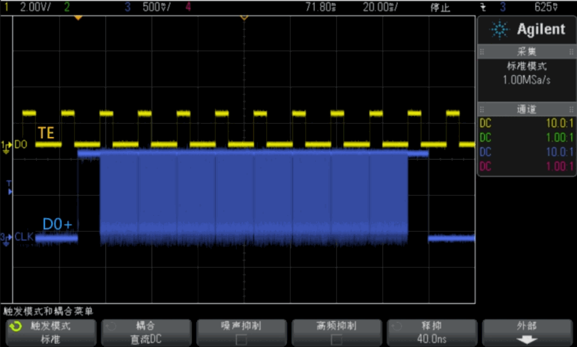
19.8 Configuring TE for a command-mode display module
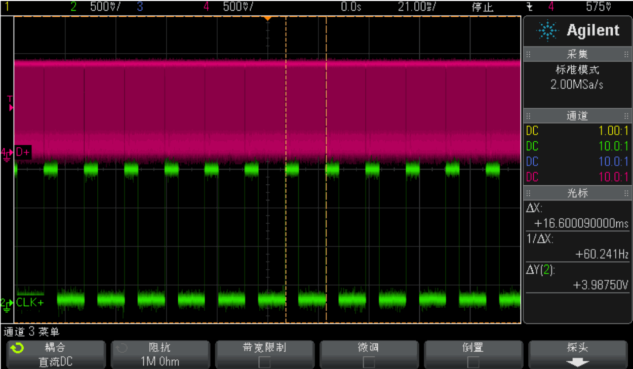
To prevent tearing, the display controller’s refresh rate should match the rate at which the display module reads images from GRAM. RK3588 and RK3576 support only external TE feedback from the display module.
19.8.1 Hardware TE
MIPI DSI has dedicated pins that can be multiplexed as TE.
&dsi0 {
    ...
    /* 显示模组TE信号连接到MIPI_TE0 */
    pinctrl-names = "default";
    pinctrl-0 = <&mipi_te0>;
    ...
};
&dsi1 {
    ...
    /* 显示模组TE信号连接到MIPI_TE1,only RK3588 support dsi1 */
    pinctrl-names = "default";
    pinctrl-0 = <&mipi_te1>;
    ...
};
19.8.2 Software TE
If the hardware TE pin is used for another function, another free GPIO can act as an input and notify the display system of TE interrupts.
&dsi0 {
    status = "okay";
    te-gpios = <&gpio0 RK_PC4 GPIO_ACTIVE_LOW>;
    pinctrl-names = "default";
    pinctrl-0 = <&lcd_te_gpio>;
};
The following capture shows the MIPI DSI data field rate matching the display module’s TE frequency:
19.9 Reversing master/slave order for dual-channel MIPI
If the two MIPI ports are reversed in the hardware design, correct their order in software with this configuration:
&dsi0 {
    ...
    rockchip,data-swap;
    rockchip,dual-channel = <&dsi1>;
    ...
};
&dsi1 {
    status = "okay";
};
19.10 Debug nodes
MIPI DSI signal testing may require signal adjustment. The relevant debug-node paths are:
dcphy0:
cd /sys/devices/platform/feda0000.phy/
dcphy1:
cd /sys/devices/platform/fedb0000.phy/
19.10.1 Patch
diff --git a/drivers/phy/rockchip/phy-rockchip-samsung-dcphy.c b/drivers/phy/rockchip/phy-rockchip-samsung-dcphy.c
index cd6b615228d9..26bb1d030d08 100644
--- a/drivers/phy/rockchip/phy-rockchip-samsung-dcphy.c
+++ b/drivers/phy/rockchip/phy-rockchip-samsung-dcphy.c
@@ -219,6 +219,25 @@
 #define RX_S0D3_DESKEW_CON4 (0xF50)
 #define RX_S0D3_ADI_STAT0 (0XFEC)
 #define MIPI_DCPHY_MAX_REGISGER RX_S0D3_ADI_STAT0
+#define REG_400M_MASK GENMASK(6, 4)
+#define REG_400M(x) UPDATE(x, 6, 4)
+#define REG_645M_MASK GENMASK(2, 0)
+#define REG_645M(x) UPDATE(x, 2, 0)
+
+#define BIAS_CON4 0x0010
+#define I_MUX_SEL_MASK GENMASK(6, 5)
+#define I_MUX_SEL(x) UPDATE(x, 6, 5)
+#define CAP_PEAKING_MASK GENMASK(14, 8)
+#define RES_UP_MASK GENMASK(7, 4)
+#define RES_UP(x) UPDATE(x, 7, 4)
+#define RES_DN_MASK GENMASK(3, 0)
+#define RES_DN(x) UPDATE(x, 3, 0)
+#define T_HS_ZERO_MASK GENMASK(15, 8)
+#define T_HS_PREPARE_MASK GENMASK(7, 0)
+#define T_HS_EXIT_MASK GENMASK(15, 8)
+#define T_HS_TRAIL_MASK GENMASK(7, 0)
+#define T_TA_GET_MASK GENMASK(7, 4)
+#define T_TA_GO_MASK GENMASK(3, 0)
 struct samsung_mipi_dphy_timing {
    unsigned int max_lane_mbps;
@@ -1780,10 +1799,10 @@ static struct v4l2_subdev *get_remote_sensor(struct v4l2_subdev *sd);
 static int samsung_mipi_dcphy_power_on(struct phy *phy)
 {
    struct samsung_mipi_dcphy *samsung = phy_get_drvdata(phy);
- enum phy_mode mode = phy_get_mode(phy);
    int on = 0;
    struct v4l2_subdev *sensor_sd = NULL;
+ samsung->mode = phy_get_mode(phy);
    pm_runtime_get_sync(samsung->dev);
    reset_control_assert(samsung->apb_rst);
    udelay(1);
@@ -1801,7 +1820,7 @@ static int samsung_mipi_dcphy_power_on(struct phy *phy)
                     RKMODULE_SET_QUICK_STREAM, &on);
    }
- switch (mode) {
+ switch (samsung->mode) {
    case PHY_MODE_MIPI_DPHY:
        samsung_mipi_dphy_power_on(samsung);
        break;
@@ -2381,6 +2400,467 @@ static const struct regmap_config samsung_mipi_dcphy_regmap_config = {
    .max_register = MIPI_DCPHY_MAX_REGISGER,
 };
+static ssize_t
+reg_645m_show(struct device *device, struct device_attribute *attr, char *buf)
+{
+ struct samsung_mipi_dcphy *samsung = dev_get_drvdata(device);
+ unsigned int val;
+ unsigned int level;
+
+ regmap_read(samsung->regmap, BIAS_CON2, &val);
+ level = (val & REG_645M_MASK) >> 4;
+
+ return sprintf(buf, "%d\n", level);
+
+}
+
+static ssize_t
+reg_645m_store(struct device *device, struct device_attribute *attr,
+ const char *buf, size_t count)
+{
+ struct samsung_mipi_dcphy *samsung = dev_get_drvdata(device);
+ unsigned long val;
+
+ if (kstrtoul(buf, 10, &val))
+ return -EINVAL;
+
+
+ if (val > 7)
+ val = 7;
+
+ regmap_update_bits(samsung->regmap, BIAS_CON2, REG_645M_MASK, REG_645M(val));
+
+ return count;
+}
+static DEVICE_ATTR_RW(reg_645m);
+
+static ssize_t
+reg_400m_show(struct device *device, struct device_attribute *attr, char *buf)
+{
+ struct samsung_mipi_dcphy *samsung = dev_get_drvdata(device);
+ unsigned int val;
+ unsigned int level;
+
+ regmap_read(samsung->regmap, BIAS_CON2, &val);
+ level = (val & REG_400M_MASK) >> 4;
+
+ return sprintf(buf, "%d\n", level);
+
+}
+
+static ssize_t
+reg_400m_store(struct device *device, struct device_attribute *attr,
+ const char *buf, size_t count)
+{
+ struct samsung_mipi_dcphy *samsung = dev_get_drvdata(device);
+ unsigned long val;
+
+ if (kstrtoul(buf, 10, &val))
+ return -EINVAL;
+
+
+ if (val > 7)
+ val = 7;
+
+ regmap_update_bits(samsung->regmap, BIAS_CON2, REG_400M_MASK, REG_400M(val));
+
+ return count;
+}
+static DEVICE_ATTR_RW(reg_400m);
+
+static ssize_t
+cap_peaking_show(struct device *device, struct device_attribute *attr, char *buf)
+{
+ struct samsung_mipi_dcphy *samsung = dev_get_drvdata(device);
+ unsigned int val;
+ unsigned int level;
+
+ regmap_read(samsung->regmap, COMBO_MD0_ANA_CON0, &val);
+ level = (val & CAP_PEAKING_MASK) >> 12;
+
+ return sprintf(buf, "%d\n", level);
+
+}
+
+static ssize_t
+cap_peaking_store(struct device *device, struct device_attribute *attr,
+ const char *buf, size_t count)
+{
+ struct samsung_mipi_dcphy *samsung = dev_get_drvdata(device);
+ unsigned long val;
+
+ if (kstrtoul(buf, 10, &val))
+ return -EINVAL;
+
+
+ if (val > 7)
+ val = 7;
+
+ regmap_update_bits(samsung->regmap, DPHY_MC_ANA_CON0, CAP_PEAKING_MASK,
+ EDGE_CON_DIR(samsung->mode == PHY_MODE_MIPI_DPHY ? 0 : 1) |
+ EDGE_CON(val) | EDGE_CON_EN);
+ regmap_update_bits(samsung->regmap, COMBO_MD0_ANA_CON0, CAP_PEAKING_MASK,
+ EDGE_CON_DIR(samsung->mode == PHY_MODE_MIPI_DPHY ? 0 : 1) |
+ EDGE_CON(val) | EDGE_CON_EN);
+ regmap_update_bits(samsung->regmap, COMBO_MD1_ANA_CON0, CAP_PEAKING_MASK,
+ EDGE_CON_DIR(samsung->mode == PHY_MODE_MIPI_DPHY ? 0 : 1) |
+ EDGE_CON(val) | EDGE_CON_EN);
+ regmap_update_bits(samsung->regmap, COMBO_MD2_ANA_CON0, CAP_PEAKING_MASK,
+ EDGE_CON_DIR(samsung->mode == PHY_MODE_MIPI_DPHY ? 0 : 1) |
+ EDGE_CON(val) | EDGE_CON_EN);
+ regmap_update_bits(samsung->regmap, DPHY_MD3_ANA_CON0, CAP_PEAKING_MASK,
+ EDGE_CON_DIR(samsung->mode == PHY_MODE_MIPI_DPHY ? 0 : 1) |
+ EDGE_CON(val) | EDGE_CON_EN);
+
+ return count;
+}
+static DEVICE_ATTR_RW(cap_peaking);
+
+static ssize_t
+res_up_show(struct device *device, struct device_attribute *attr, char *buf)
+{
+ struct samsung_mipi_dcphy *samsung = dev_get_drvdata(device);
+ unsigned int val;
+ unsigned int level;
+
+ regmap_read(samsung->regmap, COMBO_MD0_ANA_CON0, &val);
+ level = (val & RES_UP_MASK) >> 4;
+
+ return sprintf(buf, "%d\n", level);
+
+}
+
+static ssize_t
+res_up_store(struct device *device, struct device_attribute *attr,
+ const char *buf, size_t count)
+{
+ struct samsung_mipi_dcphy *samsung = dev_get_drvdata(device);
+ unsigned long val;
+
+ if (kstrtoul(buf, 10, &val))
+ return -EINVAL;
+
+
+ if (val > 15)
+ val = 15;
+
+ regmap_update_bits(samsung->regmap, DPHY_MC_ANA_CON0, RES_UP_MASK, RES_UP(val));
+ regmap_update_bits(samsung->regmap, COMBO_MD0_ANA_CON0, RES_UP_MASK, RES_UP(val));
+ regmap_update_bits(samsung->regmap, COMBO_MD1_ANA_CON0, RES_UP_MASK, RES_UP(val));
+ regmap_update_bits(samsung->regmap, COMBO_MD2_ANA_CON0, RES_UP_MASK, RES_UP(val));
+ regmap_update_bits(samsung->regmap, DPHY_MD3_ANA_CON0, RES_UP_MASK, RES_UP(val));
+
+ return count;
+}
+static DEVICE_ATTR_RW(res_up);
+
+static ssize_t
+res_dn_show(struct device *device, struct device_attribute *attr, char *buf)
+{
+ struct samsung_mipi_dcphy *samsung = dev_get_drvdata(device);
+ unsigned int val;
+ unsigned int level;
+
+ regmap_read(samsung->regmap, COMBO_MD0_ANA_CON0, &val);
+ level = (val & RES_DN_MASK);
+
+ return sprintf(buf, "%d\n", level);
+
+}
+
+static ssize_t
+res_dn_store(struct device *device, struct device_attribute *attr,
+ const char *buf, size_t count)
+{
+ struct samsung_mipi_dcphy *samsung = dev_get_drvdata(device);
+ unsigned long val;
+
+ if (kstrtoul(buf, 10, &val))
+ return -EINVAL;
+
+
+ if (val > 15)
+ val = 15;
+
+ regmap_update_bits(samsung->regmap, DPHY_MC_ANA_CON0, RES_DN_MASK, RES_DN(val));
+ regmap_update_bits(samsung->regmap, COMBO_MD0_ANA_CON0, RES_DN_MASK, RES_DN(val));
+ regmap_update_bits(samsung->regmap, COMBO_MD1_ANA_CON0, RES_DN_MASK, RES_DN(val));
+ regmap_update_bits(samsung->regmap, COMBO_MD2_ANA_CON0, RES_DN_MASK, RES_DN(val));
+ regmap_update_bits(samsung->regmap, DPHY_MD3_ANA_CON0, RES_DN_MASK, RES_DN(val));
+
+ return count;
+}
+static DEVICE_ATTR_RW(res_dn);
+
+static ssize_t
+output_voltage_show(struct device *device, struct device_attribute *attr, char *buf)
+{
+ struct samsung_mipi_dcphy *samsung = dev_get_drvdata(device);
+ unsigned int val;
+ unsigned int level;
+
+ regmap_read(samsung->regmap, BIAS_CON4, &val);
+ level = (val & I_MUX_SEL_MASK) >> 5;
+
+ return sprintf(buf, "%d\n", level);
+
+}
+
+static ssize_t
+output_voltage_store(struct device *device, struct device_attribute *attr,
+ const char *buf, size_t count)
+{
+ struct samsung_mipi_dcphy *samsung = dev_get_drvdata(device);
+ unsigned long val;
+
+ if (kstrtoul(buf, 10, &val))
+ return -EINVAL;
+
+
+ if (val > 3)
+ val = 3;
+
+ regmap_update_bits(samsung->regmap, BIAS_CON4,
+ I_MUX_SEL_MASK, I_MUX_SEL(val));
+
+ return count;
+}
+static DEVICE_ATTR_RW(output_voltage);
+
+static ssize_t
+hs_exit_show(struct device *device, struct device_attribute *attr, char *buf)
+{
+ struct samsung_mipi_dcphy *samsung = dev_get_drvdata(device);
+ unsigned int val;
+ unsigned int hs_exit;
+
+ regmap_read(samsung->regmap, COMBO_MD0_TIME_CON2, &val);
+ hs_exit = (val & GENMASK(15, 8)) >> 8;
+
+ return sprintf(buf, "%d\n", hs_exit);
+
+}
+
+static ssize_t hs_exit_store(struct device *device, struct device_attribute *attr,
+ const char *buf, size_t count)
+{
+ struct samsung_mipi_dcphy *samsung = dev_get_drvdata(device);
+ unsigned long val;
+ unsigned long hs_exit;
+
+ if (kstrtoul(buf, 10, &val))
+ return -EINVAL;
+
+ hs_exit = T_HS_EXIT(val);
+ regmap_update_bits(samsung->regmap, COMBO_MD0_TIME_CON2, T_HS_EXIT_MASK, hs_exit);
+ regmap_update_bits(samsung->regmap, COMBO_MD1_TIME_CON2, T_HS_EXIT_MASK, hs_exit);
+ regmap_update_bits(samsung->regmap, COMBO_MD2_TIME_CON2, T_HS_EXIT_MASK, hs_exit);
+
+ if (!samsung->c_option) {
+ regmap_update_bits(samsung->regmap, DPHY_MC_TIME_CON2, T_HS_EXIT_MASK, hs_exit);
+ regmap_update_bits(samsung->regmap, DPHY_MD3_TIME_CON2, T_HS_EXIT_MASK, hs_exit);
+ }
+
+ return count;
+}
+static DEVICE_ATTR_RW(hs_exit);
+
+static ssize_t
+hs_trail_or_post_3_show(struct device *device, struct device_attribute *attr, char *buf)
+{
+ struct samsung_mipi_dcphy *samsung = dev_get_drvdata(device);
+ unsigned int val;
+ unsigned int hs_trail;
+
+ regmap_read(samsung->regmap, COMBO_MD0_TIME_CON2, &val);
+ hs_trail = val & GENMASK(7, 0);
+
+ return sprintf(buf, "%d\n", hs_trail);
+
+}
+
+static ssize_t hs_trail_or_post_3_store(struct device *device, struct device_attribute *attr,
+ const char *buf, size_t count)
+{
+ struct samsung_mipi_dcphy *samsung = dev_get_drvdata(device);
+ unsigned long val;
+ unsigned long hs_trail;
+
+ if (kstrtoul(buf, 10, &val))
+ return -EINVAL;
+
+ hs_trail = T_HS_TRAIL(val);
+ regmap_update_bits(samsung->regmap, COMBO_MD0_TIME_CON2, T_HS_TRAIL_MASK, hs_trail);
+ regmap_update_bits(samsung->regmap, COMBO_MD1_TIME_CON2, T_HS_TRAIL_MASK, hs_trail);
+ regmap_update_bits(samsung->regmap, COMBO_MD2_TIME_CON2, T_HS_TRAIL_MASK, hs_trail);
+
+ if (!samsung->c_option) {
+ regmap_update_bits(samsung->regmap, DPHY_MC_TIME_CON2, T_HS_TRAIL_MASK, hs_trail);
+ regmap_update_bits(samsung->regmap, DPHY_MD3_TIME_CON2, T_HS_TRAIL_MASK, hs_trail);
+ }
+
+ return count;
+}
+static DEVICE_ATTR_RW(hs_trail_or_post_3);
+
+static ssize_t
+hs_zero_or_prebegin_3_show(struct device *device, struct device_attribute *attr, char *buf)
+{
+ struct samsung_mipi_dcphy *samsung = dev_get_drvdata(device);
+ unsigned int val;
+ unsigned int hs_zero;
+
+ regmap_read(samsung->regmap, COMBO_MD0_TIME_CON1, &val);
+ hs_zero = (val & GENMASK(15, 8)) >> 8;
+
+ return sprintf(buf, "%d\n", hs_zero);
+
+}
+
+static ssize_t hs_zero_or_prebegin_3_store(struct device *device, struct device_attribute *attr,
+ const char *buf, size_t count)
+{
+ struct samsung_mipi_dcphy *samsung = dev_get_drvdata(device);
+ unsigned long val;
+ unsigned long hs_zero;
+
+ if (kstrtoul(buf, 10, &val))
+ return -EINVAL;
+
+ hs_zero = T_HS_ZERO(val);
+ regmap_update_bits(samsung->regmap, COMBO_MD0_TIME_CON1,
+ T_HS_ZERO_MASK, hs_zero);
+ regmap_update_bits(samsung->regmap, COMBO_MD1_TIME_CON1,
+ T_HS_ZERO_MASK, hs_zero);
+ regmap_update_bits(samsung->regmap, COMBO_MD2_TIME_CON1,
+ T_HS_ZERO_MASK, hs_zero);
+
+ if (!samsung->c_option) {
+ regmap_update_bits(samsung->regmap, DPHY_MC_TIME_CON1,
+ T_HS_ZERO_MASK, hs_zero);
+ regmap_update_bits(samsung->regmap, DPHY_MD3_TIME_CON1,
+ T_HS_ZERO_MASK, hs_zero);
+ }
+
+ return count;
+}
+static DEVICE_ATTR_RW(hs_zero_or_prebegin_3);
+
+static ssize_t
+hs_prepare_or_prepare_3_show(struct device *device, struct device_attribute *attr, char *buf)
+{
+ struct samsung_mipi_dcphy *samsung = dev_get_drvdata(device);
+ unsigned int val;
+ unsigned int hs_prepare;
+
+ regmap_read(samsung->regmap, COMBO_MD0_TIME_CON1, &val);
+ hs_prepare = val & GENMASK(7, 0);
+
+ return sprintf(buf, "%d\n", hs_prepare);
+}
+
+static ssize_t hs_prepare_or_prepare_3_store(struct device *device, struct device_attribute *attr,
+ const char *buf, size_t count)
+{
+ struct samsung_mipi_dcphy *samsung = dev_get_drvdata(device);
+ unsigned long val;
+ unsigned long hs_prepare;
+
+ if (kstrtoul(buf, 10, &val))
+ return -EINVAL;
+
+ hs_prepare = T_HS_PREPARE(val);
+ regmap_update_bits(samsung->regmap, COMBO_MD0_TIME_CON1,
+ T_HS_PREPARE_MASK, hs_prepare);
+ regmap_update_bits(samsung->regmap, COMBO_MD1_TIME_CON1,
+ T_HS_PREPARE_MASK, hs_prepare);
+ regmap_update_bits(samsung->regmap, COMBO_MD2_TIME_CON1,
+ T_HS_PREPARE_MASK, hs_prepare);
+
+ if (!samsung->c_option) {
+ regmap_update_bits(samsung->regmap, DPHY_MC_TIME_CON1,
+ T_HS_PREPARE_MASK, hs_prepare);
+ regmap_update_bits(samsung->regmap, DPHY_MD3_TIME_CON1,
+ T_HS_PREPARE_MASK, hs_prepare);
+ }
+
+ return count;
+}
+static DEVICE_ATTR_RW(hs_prepare_or_prepare_3);
+
+static ssize_t
+lpx_show(struct device *device, struct device_attribute *attr, char *buf)
+{
+ struct samsung_mipi_dcphy *samsung = dev_get_drvdata(device);
+ unsigned int val;
+ unsigned int lpx;
+
+ regmap_read(samsung->regmap, COMBO_MD0_TIME_CON0, &val);
+ lpx = (val & GENMASK(11, 4)) >> 4;
+
+ return sprintf(buf, "%d\n", lpx);
+
+}
+
+static ssize_t lpx_store(struct device *device, struct device_attribute *attr,
+ const char *buf, size_t count)
+{
+ struct samsung_mipi_dcphy *samsung = dev_get_drvdata(device);
+ unsigned long val;
+ unsigned long lpx = 0;
+
+ if (kstrtoul(buf, 10, &val))
+ return -EINVAL;
+
+ lpx |= T_LPX(val);
+ /* T_LP_EXIT_SKEW/T_LP_ENTRY_SKEW unconfig */
+ regmap_write(samsung->regmap, COMBO_MD0_TIME_CON0, lpx);
+ regmap_write(samsung->regmap, COMBO_MD1_TIME_CON0, lpx);
+ regmap_write(samsung->regmap, COMBO_MD2_TIME_CON0, lpx);
+
+ if (!samsung->c_option) {
+ regmap_write(samsung->regmap, DPHY_MC_TIME_CON0, lpx);
+ regmap_write(samsung->regmap, DPHY_MD3_TIME_CON0, lpx);
+ }
+
+ return count;
+}
+static DEVICE_ATTR_RW(lpx);
+
+static struct attribute *samsung_mipi_dcphy_cts_attrs[] = {
+ &dev_attr_lpx.attr,
+ &dev_attr_hs_prepare_or_prepare_3.attr,
+ &dev_attr_hs_zero_or_prebegin_3.attr,
+ &dev_attr_hs_trail_or_post_3.attr,
+ &dev_attr_hs_exit.attr,
+ &dev_attr_output_voltage.attr,
+ &dev_attr_res_up.attr,
+ &dev_attr_res_dn.attr,
+ &dev_attr_cap_peaking.attr,
+ &dev_attr_reg_400m.attr,
+ &dev_attr_reg_645m.attr,
+ NULL
+};
+
+static const struct attribute_group samsung_mipi_dcphy_cts_attr_group = {
+ .attrs = samsung_mipi_dcphy_cts_attrs,
+};
+
+static int samsung_mipi_dcphy_cts_sysfs_add(struct samsung_mipi_dcphy *samsung)
+{
+ struct device *dev = samsung->dev;
+ int ret;
+
+ ret = sysfs_create_group(&dev->kobj, &samsung_mipi_dcphy_cts_attr_group);
+ if (ret) {
+ dev_err(dev, "failed to register sysfs. err: %d\n", ret);
+ return ret;
+ };
+
+ return 0;
+}
+
+
 static int samsung_mipi_dcphy_probe(struct platform_device *pdev)
 {
    struct device *dev = &pdev->dev;
@@ -2474,6 +2954,7 @@ static int samsung_mipi_dcphy_probe(struct platform_device *pdev)
    samsung->stream_off = samsung_dcphy_rx_stream_off;
    mutex_init(&samsung->mutex);
    pm_runtime_enable(dev);
+ samsung_mipi_dcphy_cts_sysfs_add(samsung);
    return 0;
 }
diff --git a/drivers/phy/rockchip/phy-rockchip-samsung-dcphy.h b/drivers/phy/rockchip/phy-rockchip-samsung-dcphy.h
index b5e827d7cfc1..a53356c0eed6 100644
--- a/drivers/phy/rockchip/phy-rockchip-samsung-dcphy.h
+++ b/drivers/phy/rockchip/phy-rockchip-samsung-dcphy.h
@@ -48,6 +48,7 @@ struct samsung_mipi_dcphy {
    struct clk *pclk;
    struct regmap *regmap;
    struct regmap *grf_regmap;
+ int mode;
    struct reset_control *m_phy_rst;
    struct reset_control *s_phy_rst;
    struct reset_control *apb_rst;
19.10.2 Drive strength
19.10.2.1 Output-voltage selection pin (400mV/200mV/530mV)
echo level > output_voltage
Driver defaults:
1. D-PHY: 2’b00
2. C-PHY: 2’b10
Level reference:
1. 2b’00 : 400mV
2. 2b’01 : 200mV
3. 2b’10 : 530mV
4. 2b’11 : 530mV
19.10.2.2 LP common-mode voltage
echo level > reg_645m
Level reference:
LP function control pin reference voltage: 645mV
1. 3’b000: 605mV
2. 3’b001: 625mV
3. 3’b010: 635mV
4. 3’b011: 645mV
5. 3’b100: 655mV
6. 3’b101: 665mV
7. 3’b110: 685mV
8. 3’b111: 725mV
19.10.2.3 HS common-mode voltage
echo level > reg_400m
Level reference:
1. 3’b000: 380mV / 230mV
2. 3’b001: 390mV / 220mV
3. 3’b010: 400mV / 210mV
4. 3’b011: 410mV / 200mV
5. 3’b100: 420mV / 190mV
6. 3’b101: 430mV / 180mV
7. 3’b110: 440mV / 170mV
8. 3’b111: 450mV / 160mV
19.10.2.4 HS differential-mode voltage
High-speed differential voltage is determined jointly by the configurable pull-up and pull-down resistors below:
VREG corresponds to the common-mode voltage (REG_400M register field).
19.10.2.4.1 High-speed driver pull-up resistor control
echo level > res_up
Level reference:
1. 4’b0000: 43 ohm
2. 4’b0001: 46 ohm
3. 4’b0010: 49 ohm
4. 4’b0011: 52 ohm
5. 4’b0100: 56 ohm
6. 4’b0101: 60 ohm
7. 4’b0110: 66 ohm
8. 4’b0111: 73 ohm
9. 4’b1000: 30 ohm
10. 4’b1001: 31.2 ohm
11. 4’b1010: 32.5 ohm
12. 4’b1011: 34 ohm
13. 4’b1100: 35.5 ohm
14. 4’b1101: 37 ohm
15. 4’b1110: 39 ohm
16. 4’b1111: 41 ohm
19.10.2.4.2 High-speed driver pull-down resistor control
echo level > res_dn
Level reference:
1. 4’b0000: 43 ohm
2. 4’b0001: 46 ohm
3. 4’b0010: 49 ohm
4. 4’b0011: 52 ohm
5. 4’b0100: 56 ohm
6. 4’b0101: 60 ohm
7. 4’b0110: 66 ohm
8. 4’b0111: 73 ohm
9. 4’b1000: 30 ohm
10. 4’b1001: 31.2 ohm
11. 4’b1010: 32.5 ohm
12. 4’b1011: 34 ohm
13. 4’b1100: 35.5 ohm
14. 4’b1101: 37 ohm
15. 4’b1110: 39 ohm
16. 4’b1111: 41 ohm
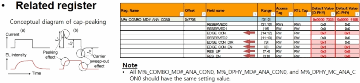
19.10.2.5 Cap peaking
Editable transcription of the original figure:
Related register: M%_COMBO_MD#_ANA_CON0, offset 0x0708, range [31:0], D-PHY default 0x0000_7333, C-PHY default 0x0000_1188.
| Field | Range | Access Tag | RTL Tag | D-PHY | C-PHY |
|---|---|---|---|---|---|
| RESERVED0 | [31:16] | RWi | RWi | 0x0 | 0x0 |
| RESERVED1 | [15] | R/W | 0x0 | 0x0 | |
| EDGE_CON | [14:12] | R/W | 0x7 | 0x1 | |
| RESERVED2 | [11:10] | R/W | 0x0 | 0x0 | |
| EDGE_CON_DIR | [9] | R/W | 0x1 | 0x0 | |
| EDGE_CON_EN | [8] | R/W | 0x1 | 0x1 | |
| RES_UP | [7:4] | R/W | 0x3 | 0x8 | |
| RES_DN | [3:0] | R/W | 0x3 | 0x8 |
Source note: all M%_COMBO_MD#_ANA_CON0, M%_DPHY_MD#_ANA_CON0 and M%_DPHY_MC_ANA_CON0 should use the same setting. The left conceptual diagram shows current, EL intensity, time, peaking effect and carrier sweep-out effect.
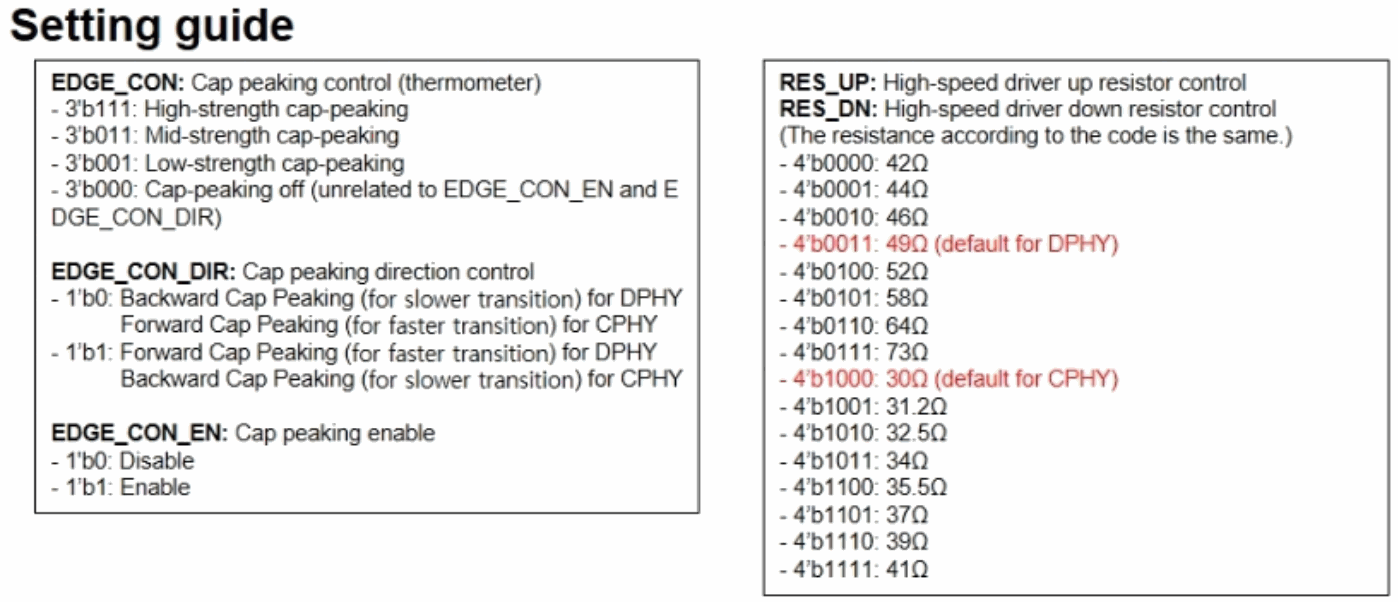
Editable transcription of the original figure:
| Field | Value | Meaning |
|---|---|---|
| EDGE_CON | 3’b111 | High-strength cap-peaking |
| EDGE_CON | 3’b011 | Mid-strength cap-peaking |
| EDGE_CON | 3’b001 | Low-strength cap-peaking |
| EDGE_CON | 3’b000 | Off, independent of EDGE_CON_EN/EDGE_CON_DIR |
| EDGE_CON_DIR | 1’b0 | D-PHY backward (slower transition); C-PHY forward (faster transition) |
| EDGE_CON_DIR | 1’b1 | D-PHY forward (faster transition); C-PHY backward (slower transition) |
| EDGE_CON_EN | 1’b0 | Disabled |
| EDGE_CON_EN | 1’b1 | Enabled |
EDGE_CON uses thermometer coding. RES_UP and RES_DN control high-speed pull-up/pull-down resistance; equal codes have equal resistance. The table preserves source-figure values, which differ from the body values 43/46/49/52/56/60/66 ohm at some levels. They are not silently reconciled.
| RES_UP / RES_DN | ohm | Default |
|---|---|---|
| 4’b0000 | 42 | |
| 4’b0001 | 44 | |
| 4’b0010 | 46 | |
| 4’b0011 | 49 | D-PHY |
| 4’b0100 | 52 | |
| 4’b0101 | 58 | |
| 4’b0110 | 64 | |
| 4’b0111 | 73 | |
| 4’b1000 | 30 | C-PHY |
| 4’b1001 | 31.2 | |
| 4’b1010 | 32.5 | |
| 4’b1011 | 34 | |
| 4’b1100 | 35.5 | |
| 4’b1101 | 37 | |
| 4’b1110 | 39 | |
| 4’b1111 | 41 |
echo level > cap_peaking
level: 0~7
19.10.3 Signal timing
The signal parameters in the red rectangles below can all be adjusted.
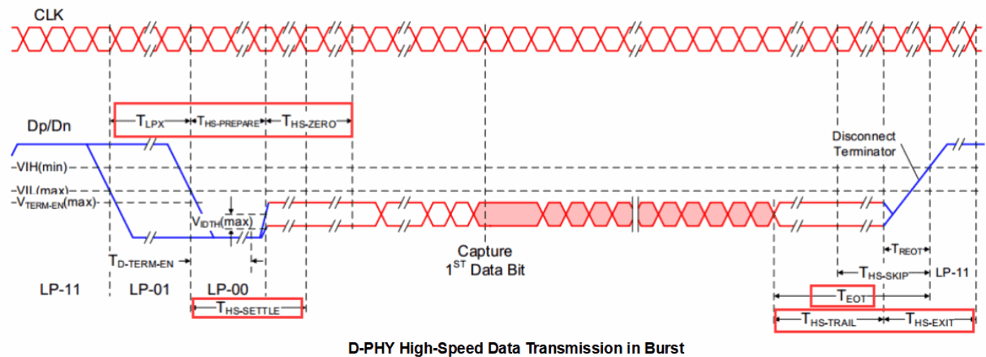
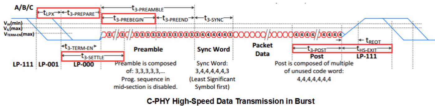
Adjust the signal count values relative to their readback values, for example Tlpx:
cat lpx
19.10.3.1 Tlpx
echo count > lpx
19.10.3.2 Ths_prepare_or_prepare_3
echo count > hs_prepare_or_prepare_3
19.10.3.3 Ths_zero_or_prebegin_3
echo count > hs_zero_or_prebegin_3
19.10.3.4 Ths_trail_or_post_3
echo count > hs_trail_or_post_3
19.10.3.5 Ths_exit
echo count > hs_exit