
Grundlage sind die chinesischen und englischen Rockchip-Dokumente V7.0.1 vom 2024-04-16. Alle technischen Inhalte der Kapitel 1–10, Konfigurationen, Codebeispiele, Testabbildungen und Tabellen bleiben erhalten. Kapitel 11 enthält nur FTP-Kontakt-/Anmeldedaten und entfällt. Diese ArmSoM-Referenz bestätigt nicht die Unterstützung aller Module auf jeder Platine: Prüfen Sie SoC, SDK/BSP, Kernel, Schaltplan, Versorgung und Modulfirmware. Befehle, Messwerte und Protokolle stammen aus der Quelle; es wurden keine Befehle oder Hardware-/RF-Tests ausgeführt.
Die jeweilige Quellnummerierung bleibt erhalten: Englisch ergänzt die Abbildungsüberschrift 2.2.4.1. Wi-Fi-/BT- und Antennenpunkte unter chinesisch 4.8.1 werden englisch 4.8.2/4.8.3; chinesische Testmethoden 4.8.2 entsprechen englisch 4.8.4. Einige Querverweise verwenden alte Nummern (7.1.1, 7.2, 8.1); suchen Sie nach dem Abschnittstitel. Schreibweisen Synopsys, Bcm44338a1.hcd/bcm43438a1.hcd, udhcpcd, reset gopios, GPIO-Polaritätskommentare und IRQ-CPU-Nummern müssen anhand SDK/Datenblatt geprüft werden. Code und Kommentare behalten die Quellsprache; Abbildungen sind Originale aus dem englischen Dokument.
Die Originalabbildungen enthalten gemischte chinesische und englische Beschriftungen. RF- und Antennenberichte sind zusätzlich als bearbeitbare Tabellen wiedergegeben.
| SoC | Linux |
|---|---|
| RK356X, RK3399, RK3326, RK3288, RK3308, RV1109, RV1126, PX30 | 4.4 / 4.19 |
| RK3588, RK3566, RK3568, RK3399, RV1106, RV1103 | 5.10 |
1. Vorwort
Dieses Dokument beschreibt Konfiguration, Fehlersuche, Entwicklung und Anwendung von Wi-Fi/BT einschließlich SDKs für Buildroot, IPC, stromsparende Produkte und Debian.
2. Wi-Fi-/BT-Konfiguration
2.1 SDK-Konfiguration
Wählen Sie zunächst Chip und Platine mit ./build.sh chip. Die Standardkonfiguration kann geändert werden; im Folgenden wird dieser deconfig angenommen:
SDK_ROOT/device/rockchip$
+++ b/rk3588/rockchip_rk3588_evb1_lp4_v10_defconfig
@@ -1,4 +1,5 @@
 RK_YOCTO_CFG="rockchip-rk3568-evb"
+RK_WIFIBT_CHIP="ALL_AP"   //Note the colon ""
 RK_KERNEL_DTS_NAME="rk3568-evb1-ddr4-v10-linux" //The specific dts file used
 RK_PARAMETER="parameter-buildroot-fit.txt"
Wählen Sie das Wi-Fi-Modell in make menuconfig über RK_WIFIBT_CHIP (Suche mit „/“). ALL_AP unterstützt alle im SDK enthaltenen Synopsys-(AMPAK)- und Realtek-Module; ALL_CY alle Infineon- und Realtek-Module. Einzelauswahl: AP6275/AP6358S/AP6212/AP6236 … RTL8723DS/RTL8822CS … CYW4354/CYW43438/CYW5557X_PCIE/CYW5557X_PCIE. Unterstützte Modelle:
device/rockchip/common/scripts/post-wifibt.sh
156:    if [[ "$RK_WIFIBT_CHIP" = "AP6275_PCIE" ]];then
167:    if [[ "$RK_WIFIBT_CHIP" = "CYW4354" ]];then
174:    if [[ "$RK_WIFIBT_CHIP" = "CYW4373" ]];then
181:    if [[ "$RK_WIFIBT_CHIP" = "CYW43438" ]];then
188:    if [[ "$RK_WIFIBT_CHIP" = "CYW43455" ]];then
195:    if [[ "$RK_WIFIBT_CHIP" = "CYW5557X" ]];then
202:    if [[ "$RK_WIFIBT_CHIP" = "CYW5557X_PCIE" ]];then
209:    if [[ "$RK_WIFIBT_CHIP" = "CYW54591" ]];then
216:    if [[ "$RK_WIFIBT_CHIP" = "CYW54591_PCIE" ]];then
223:    if [[ "$RK_WIFIBT_CHIP" = "RTL8188FU" ]];then
228:    if [[ "$RK_WIFIBT_CHIP" = "RTL8189FS" ]];then
233:    if [[ "$RK_WIFIBT_CHIP" = "RTL8723DS" ]];then
237:    if [[ "$RK_WIFIBT_CHIP" = "RTL8821CS" ]];then
241:    if [[ "$RK_WIFIBT_CHIP" = "RTL8822CS" ]];then
245:    if [[ "$RK_WIFIBT_CHIP" = "RTL8852BS" ]];then
249:    if [[ "$RK_WIFIBT_CHIP" = "RTL8852BE" ]];then
280:    if [[ "$RK_WIFIBT_CHIP" = "ALL_CY" ]];then
299:    if [[ "$RK_WIFIBT_CHIP" = "ALL_AP" ]];then
Weitere Modelle, etwa chinesische AIC- und ATBM-Module, werden durch Materialien auf dem FTP-Server unterstützt.
2.2 DTS-Konfiguration
Konfigurieren Sie DTS unbedingt anhand des Schaltplans.
2.2.1 SDIO-Wi-Fi-Konfiguration
Zwei Verfahren unterscheiden sich hauptsächlich bei Stromsteuerung und Erkennungszeitpunkt. Standardframework: Der einfache MMC-Power-Sequence-Provider unterstützt gemeinsame Eigenschaften verschiedener SoC-Designs, sodass derselbe Provider mehrfach verwendet werden kann (mmc-pwrseq-simple). Wi-Fi REG_ON wird vom mmc-Framework gesteuert; siehe kernel/drivers/mmc/core/pwrseq_simple.c. Vorteil: einheitliche Verwaltung aller Wi-Fi-Versorgungen durch mmc. Nachteil: erneute SDIO-Kartenerkennung wird nicht unterstützt.
/* System-on-Chip designs may specify a specific
   * MMC power sequence. To successfully detect an
   * SDIO card, that power sequence must be maintained
   * while initializing the card.
   */
sdio_pwrseq: sdio-pwrseq {
  compatible = "mmc-pwrseq-simple";
  pinctrl-names = "default";
  pinctrl-0 = <&wifi_enable_h>;

  /* reset-gpios:
   * contains a list of GPIO specifiers. The reset GPIOs are asserted
   * at initialization and prior we start the power up procedure of the
   * card. They will be de-asserted right after the power has been
   * provided to the card.
   *
   * Alias: WIFI_REG_ON/WL_REG_ON etc (schematic diagram)
   * Notes:
   * GPIO_ACTIVE_LOW: Active HIGH
   * GPIO_ACTIVE_LOW: Active LOW
   */
  reset-gpios = <&gpio0 RK_PA2 GPIO_ACTIVE_LOW>;

  /*
   * Default: disabled
   */
  //clocks = <&clk_32768_ck>;  //Handle for the entry in clock-names.
  //clock-names = "ext_clock"; //32.768K: External clock provided to the card.

  /* It's reused as a tunable delay waiting for I/O signaling
   * and card power supply to be stable, regardless of whether
   * pwrseq-simple is used. Default to 10ms if no available.
   *
   * Delay in ms after powering the card and de-asserting the
   * reset-gpios (if any).
   *
   * Default: disabled
   */
  //post-power-on-delay-ms = <200>;

  /* Delay in us after asserting the reset-gpios (if any)
   * during power off of the card.
   *
   * Default: disabled
   */
  //power-off-delay-us = <200>;
};

/* Related to reset-gpio above */
&pinctrl {
  sdio-pwrseq {
    wifi_enable_h: wifi-enable-h {
      rockchip,pins =
      <0 RK_PA2 RK_FUNC_GPIO &pcfg_pull_none>;
    };
  };
};

/* SDIO
 * https://elixir.bootlin.com/linux/latest/source/
 * Documentation/devicetree/bindings/mmc/mmc-controller.yaml
 */
&sdio {
  /*
   * Description:
   * Maximum operating frequency of the bus:
   *  - for SD/SDIO cards the SDR104 mode has a max supported
   *    frequency of 150 or 200MHz,
   * So, lets keep the maximum supported value here.
   */
  max-frequency = <150000000>;

  /* Number of data lines. */
  bus-width = <4>;

  /* SD high-speed timing is supported. */
  cap-sd-highspeed;

  /* SD UHS SDR104 speed is supported. */
  sd-uhs-sdr104;

  /*
   * Controller is limited to send SD commands during initialization.
   * Controller is limited to send MMC commands during initialization.
   */
  no-sd;
  no-mmc;

  /* Non-removable slot (like SDIO Wi-Fi); assume always present. */
  non-removable;

  /* enable SDIO IRQ signaling on this interface */
  cap-sdio-irq;

  /* SDIO only. Preserves card power during a suspend/resume cycle. */
  keep-power-in-suspend;

  /* Enable pwrseq*/
  mmc-pwrseq = <&sdio_pwrseq>;

  status = "okay";
};

/* Rockchip Soc Wi-Fi node */
wireless-wlan {
  compatible = "wlan-platdata";
  rockchip,grf = <&grf>;

  /* Attention: If the Wi-Fi module requires 32.768K and is supplied
   * by the Power Management Integrated Circuit (PMIC) as indicated
   * in the schematic, open the following properties and fill in the
   * relevant attributes according to the actual PMIC model used.
   */
  clocks = <&rk809 1>;  //RK809
  clocks = <&hym8563>;  //or hym8563
  clock-names = "ext_clock";

  /* The name of the Wi-Fi, without any specific constraints,
   * serves merely as a suggestive indicator.
   */
  wifi_chip_type = "ap6255";

  /* WIFI_WAKE_HOST: The Wi-Fi chip issues an interrupt notification
   * to the System on Chip (SOC) through this pin for further operations.
   * Special attention: Please verify the connection relationship between
   * this pin and the main controller(SOC); the configuration for a direct
   * connection is GPIO_ACTIVE_HIGH. If an inverted tube is introduced
   * in between, the configuration should be set to GPIO_ACTIVE_LOW.
   */
  WIFI,host_wake_irq = <&gpio0 RK_PA0 GPIO_ACTIVE_HIGH>;

  status = "okay";
};

wireless-wlan {
  /omit-if-no-ref/
  wifi_wake_host: wifi-wake-host {
    /* The initial state of the interrupt pin.*/
    rockchip,pins = <0 RK_PA0 0 &pcfg_pull_none>;
  };
};
Traditionelles Framework: net/rfkill/rfkill-wlan.c steuert Wi-Fi REG_ON. Mehrfaches rmmod/insmod des Treibers ist möglich; der KO-Modus-Patch ist erforderlich.
/* Wi-Fi */
wireless-wlan {
  compatible = "wlan-platdata";
  rockchip,grf = <&grf>;
  clocks = <&rk809 1>;  //RK809
  clocks = <&hym8563>;  //or hym8563
  clock-names = "ext_clock";
  wifi_chip_type = "ap6255";
  WIFI,host_wake_irq = <&gpio0 RK_PA0 GPIO_ACTIVE_HIGH>;
  WIFI,poweren_gpio = <&gpio0 RK_PA2 GPIO_ACTIVE_HIGH>;
  status = "okay";
};

&sdio {
  max-frequency = <150000000>;
  bus-width = <4>;
    cap-sd-highspeed;
  sd-uhs-sdr104;
    no-sd;
    no-mmc;
    cap-sdio-irq;
    keep-power-in-suspend;

  /* delete-property */
  /delete-property/ non-removable;
  /delete-property/ mmc-pwrseq = <&sdio_pwrseq>;

  status = "okay";
};

wireless-wlan {
  /omit-if-no-ref/
  wifi_wake_host: wifi-wake-host {
    rockchip,pins = <0 RK_PA0 0 &pcfg_pull_none>;
  };
};
2.2.2 Bluetooth-Konfiguration
Konfigurieren Sie die Pins des tatsächlich verwendeten UART-Ports. Verbinden Sie RTS/CTS unbedingt gemäß SDK; siehe Bluetooth-Hinweise. Besonders wichtig: Viele Initialisierungsfehler entstehen durch fehlende oder falsche Verbindung dieser beiden Pins. Das Beispiel verwendet UART4:
/* Note the following UART configurations: uart4_xfer/uart4_rts/uart4_ctsn
 * The names for each platform may vary, so you need to look for the
 * corresponding UART notation in the dts/dtsi of the specific chip platform,
 * such as uart4_ctsn,which may be named uart4_cts on some platforms.
 */
wireless-bluetooth {
    compatible = "bluetooth-platdata"

    /* Must be configured and ensure it is correct
     * Configure the RTS pin corresponding to the UART of the SoC here
     * The special configuration is because some Bluetooth chips need to keep
     * the CTS pin low before power-on, otherwise, they will enter test mode
     * or other abnormal working modes. Therefore, the driver will pull it low
     * before power-on,through pinctrl-1, and switch back to the RTS function
     * after power-on, through pinctrl-0;
     */
    uart_rts_gpios = <&gpio4 RK_PA7 GPIO_ACTIVE_LOW>;
    pinctrl-names = "default", "rts_gpio";
    pinctrl-0 = <&uart4_rts>;
    pinctrl-1 = <&uart4_rts_gpio>;

    /* BT_REG_ON Bluetooth power switch */
    BT,power_gpio = <&gpio4 RK_PB3 GPIO_ACTIVE_HIGH>;

    /* Linux platform: The following two configurations do not need to be set */
    //BT,wake_host_irq = <&gpio4 RK_PB4 GPIO_ACTIVE_HIGH>; /* BT_WAKE_HOST */
    //BT,wake_gpio = <&gpio4 31 GPIO_ACTIVE_HIGH>; /* HOST_WAKE_BT */
    status = "okay";
};

/* Open the corresponding UART configuration */
&uart4 {
    pinctrl-names = "default";
    /* Configure the TX/RX/CTS PINs corresponding to the UART of the SoC here, do
not configure the RTS PIN */
    pinctrl-0 = <&uart4_xfer &uart4_ctsn>;
    status = "okay";
};

/* uart4_rts_gpio */
&pinctrl {
    wireless-bluetooth {
        uart4_rts_gpio: uart4-rts-gpio {
            rockchip,pins = <4 RK_PA7 RK_FUNC_GPIO &pcfg_pull_none>;
        };
    };
};
Optionale Upstream-Konfiguration für Kernel 6.1 broadcom-bluetooth
# SPDX-License-Identifier: (GPL-2.0 OR BSD-2-Clause)
%YAML 1.2
---
$id: http://devicetree.org/schemas/net/broadcom-bluetooth.yaml#
$schema: http://devicetree.org/meta-schemas/core.yaml#

title: Broadcom Bluetooth Chips

maintainers:
  - Linus Walleij <linus.walleij@linaro.org>

description:
  This binding describes Broadcom UART-attached Bluetooth chips.

properties:
  compatible:
    enum:
      - brcm,bcm20702a1
      - brcm,bcm4329-bt
      - brcm,bcm4330-bt
      - brcm,bcm4334-bt
      - brcm,bcm43430a0-bt
      - brcm,bcm43430a1-bt
      - brcm,bcm43438-bt
      - brcm,bcm4345c5
      - brcm,bcm43540-bt
      - brcm,bcm4335a0
      - brcm,bcm4349-bt
      - cypress,cyw4373a0-bt
      - infineon,cyw55572-bt

  shutdown-gpios:
    maxItems: 1
    description: GPIO specifier for the line BT_REG_ON used to
      power on the BT module

  reset-gpios:
    maxItems: 1
    description: GPIO specifier for the line BT_RST_N used to
      reset the BT module. This should be marked as
      GPIO_ACTIVE_LOW.

  device-wakeup-gpios:
    maxItems: 1
    description: GPIO specifier for the line BT_WAKE used to
      wakeup the controller. This is using the BT_GPIO_0
      pin on the chip when in use.
host-wakeup-gpios:
  maxItems: 1
  deprecated: true
  description: GPIO specifier for the line HOST_WAKE used
    to wakeup the host processor. This is using he BT_GPIO_1
    pin on the chip when in use. This is deprecated and replaced
    by interrupts and "host-wakeup" interrupt-names

clocks:
  minItems: 1
  maxItems: 2
  description: 1 or 2 clocks as defined in clock-names below,
    in that order

clock-names:
  description: Names of the 1 to 2 supplied clocks
  oneOf:
    - const: extclk
      deprecated: true
      description: Deprecated in favor of txco

    - const: txco
      description: >
        external reference clock (not a standalone crystal)

    - const: lpo
      description: >
        external low power 32.768 kHz clock

    - items:
        - const: txco
        - const: lpo

vbat-supply:
  description: phandle to regulator supply for VBAT

vddio-supply:
  description: phandle to regulator supply for VDDIO

brcm,bt-pcm-int-params:
  $ref: /schemas/types.yaml#/definitions/uint8-array
  minItems: 5
  maxItems: 5
  description: |-
    configure PCM parameters via a 5-byte array:
     sco-routing: 0 = PCM, 1 = Transport, 2 = Codec, 3 = I2S
     pcm-interface-rate: 128KBps, 256KBps, 512KBps, 1024KBps, 2048KBps
     pcm-frame-type: short, long
     pcm-sync-mode: slave, master
     pcm-clock-mode: slave, master

brcm,requires-autobaud-mode:
  type: boolean
  description:
    Set this property if autobaud mode is required. Autobaud mode is required
      if the device's initial baud rate in normal mode is not supported by the
      host or if the device requires autobaud mode startup before loading FW.

  interrupts:
    items:
      - description: Handle to the line HOST_WAKE used to wake
          up the host processor. This uses the BT_GPIO_1 pin on
          the chip when in use.

  interrupt-names:
    items:
      - const: host-wakeup

  max-speed: true
  current-speed: true

required:
  - compatible

dependencies:
  brcm,requires-autobaud-mode: [ shutdown-gpios ]

if:
  not:
    properties:
      compatible:
        contains:
          enum:
            - brcm,bcm20702a1
            - brcm,bcm4329-bt
            - brcm,bcm4330-bt
then:
  properties:
    reset-gpios: false

additionalProperties: false

examples:
  - |
    #include <dt-bindings/gpio/gpio.h>
    #include <dt-bindings/interrupt-controller/irq.h>

    uart {
        uart-has-rtscts;

        bluetooth {
            compatible = "brcm,bcm4330-bt";
            max-speed = <921600>;
            brcm,bt-pcm-int-params = [01 02 00 01 01];
            shutdown-gpios = <&gpio 30 GPIO_ACTIVE_HIGH>;
            device-wakeup-gpios = <&gpio 7 GPIO_ACTIVE_HIGH>;
            reset-gpios = <&gpio 9 GPIO_ACTIVE_LOW>;
            interrupt-parent = <&gpio>;
            interrupts = <8 IRQ_TYPE_EDGE_FALLING>;
        };
    };
2.2.3 Konfiguration der IO-Spannungsdomäne
Wichtig: Beachten Sie die Spannungsdomänen-Anleitung des jeweiligen SDK. SDIO3.0-Geräte müssen mit folgender Spannung versorgt werden:
1,8 V.
//Note that the names of io_domains vary for each platform, some are written as
&pmu_io_domains;
&io_domains {
//or
&pmu_io_domains {
 /* VDDIO3_VDD references the voltage of vcc_1v8, if the hardware is connected to
3.3v, then change to vcc_3v3,
  * Note: The names vcc_1v8/vcc_3v3 should be adjusted according to the actual
dts/dtsi.
  */
 vccio3-supply = <&vcc_1v8>;
};

vcc_1v8: vcc_1v8: vcc-1v8 {
 compatible = "regulator-fixed";
 regulator-name = "vcc_1v8";
 regulator-always-on;
 regulator-boot-on;
 /* vcc_1v8 supplies 1.8v */
 regulator-min-microvolt = <1800000>;
 regulator-max-microvolt = <1800000>;
 vin-supply = <&vcc_io>;
};
2.2.4 PCIE-Wi-Fi-Konfiguration
Lesen Sie unbedingt die SDK-Dokumente docs\Common\PCIe\Rockchip_RK3399_Developer_Guide_PCIe_EN.pdf, docs\Common\PCIe\Rockchip_RK356X_Developer_Guide_PCIe_EN.pdf und docs\Common\PCIe\Rockchip_Developer_Guide_PCIe_EN.pdf. Ermitteln Sie drei Schlüsselsignale im Schaltplan. PCIe-Wi-Fi gibt es als aufgelötetes Modul oder M2; die Grundprinzipien sind gleich. VBAT/VCC3V3 ist die normalerweise dauerhafte 3,3-V-Versorgung. WIFI_REG_ON ist der beim Start auf High gehaltene SoC-Reset-/Enable-Pin. PCIE_PERST_L/PERSTO setzt den PCIe-Teil des SoC zurück und muss im entsprechenden PCIE-DTS-Knoten korrekt konfiguriert sein.
Konfigurieren Sie Controller und PHY anhand des Schaltplans und der drei genannten Dokumente. Einfaches Beispiel:
// PHY node, the name varies depending on the chip, some are called
&combphy2_psq, the actual name refers to the three documents above;
&pcieXXphy {
    status = "okay";
};

/* If using pcie2x1l2, sata0 and pcie2x1l2 share combphy0_ps,
/* it is necessary to ensure that it is disabled
 */
&sata0 {
    status = "disabled";
}

// Controller node, specifically which controller node to connect to
&pcixxx {
 /* This item sets the PERST# reset signal of the PCIe interface;
 /* whether it is a slot or a soldered device, please find the pin
 /* on the schematic and configure it correctly,
  * otherwise, the link establishment will not be completed.
  * Choose one of the following
  */
    ep-gpios = <&gpio3 13 GPIO_ACTIVE_HIGH>; // RK3399 platform
    reset-gpios = <&gpio4 RK_PA5 GPIO_ACTIVE_HIGH>; // RK356X/3588 platform

    num-lanes = <4>;
    rockchip,skip-scan-in-resume;
    rockchip,perst-inactive-ms = <500>;  /* Refer to the Wi-Fi module manual for
the required #PERST reset time */
    vpcie3v3-supply = <&vcc3v3_pcie20_wifi>;
    status = "okay";
};

// Configure the Wi-Fi REG ON of the PCIe Wi-Fi to pull high during the boot
identification phase
vcc3v3_pcie20_wifi: vcc3v3-pcie20-wifi {
    compatible = "regulator-fixed";
    regulator-name = "vcc3v3_pcie20_wifi";
    regulator-min-microvolt = <3300000>;
    regulator-max-microvolt = <3300000>;
    enable-active-high;
    /*
    * wifi_reg_on is enabled after vbat, vddio is stable, and before reset-gpios
is
    * pulled high, so it is placed in the PCIe power node to meet the module
timing,
    * referring to wifi_poweron_gpio.
    */
    pinctrl-0 = <&wifi_poweron_gpio>
    startup-delay-us = <5000>;
    vin-supply = <&vcc12v_dcin>;
};
// Wi-Fi node configuration
wireless_wlan: wireless-wlan {
    compatible = "wlan-platdata";
    wifi_chip_type = "ap6275p";
    // Configuration: WIFI_REG_ON, for use by the Wi-Fi driver
    WIFI,poweren_gpio = <&gpio0 RK_PA2 GPIO_ACTIVE_HIGH>;
    // Configuration: WIFI_HOST_WAKE, if any
    WIFI,host_wake_irq = <&gpio0 RK_PA0 GPIO_ACTIVE_HIGH>;
    status = "okay";
};

&pinctrl {
    wireless-wlan {
        wifi_poweren_gpio: wifi-poweren-gpio {
            //PCIE REG ON: 务必配置成上拉
            rockchip,pins = <0 RK_PA2 RK_FUNC_GPIO &pcfg_pull_up>;
        };
    };
};
2.2.4.1 Zuordnung von RK3588-Schaltplan und PCIE20-dtsi
//PCIE20_0 -> pcie2x1l2
PCIE20_0_REFCLKP
PCIE20_0_REFCLKN
PCIE20_0_TXP
PCIE20_0_TXN
PCIE20_0_RXP
PCIE20_0_RXN

&combphy0_ps {
 status = "okay";
};

//pcie@fe190000
&pcie2x1l2 {
    reset-gpios = <&gpio1 RK_PB4 GPIO_ACTIVE_HIGH>;
    status = "okay";
};

//PCIE20_1 -> pcie2x1l0
PCIE20_1_REFCLKP
PCIE20_1_REFCLKN
PCIE20_1_TXP
PCIE20_1_TXN
PCIE20_1_RXP
PCIE20_1_RXN

&combphy1_ps {
    status = "okay";
};

&pcie2x1l0 {   //pcie@fe170000
    reset-gpios = <&gpio1 RK_PB4 GPIO_ACTIVE_HIGH>;
    status = "okay";
};

//PCIE20_2 -> pcie2x1l1
PCIE20_2_REFCLKP
PCIE20_2_REFCLKN
PCIE20_2_TXP
PCIE20_2_TXN
PCIE20_2_RXP
PCIE20_2_RXN

&combphy2_psu {
    status = "okay";
};

&pcie2x1l1 { //pcie@fe180000
    reset-gpios = <&gpio1 RK_PB4 GPIO_ACTIVE_HIGH>;
    status = "okay";
};
2.2.5 USB-Wi-Fi-Konfiguration
Lesen Sie unbedingt docs\Common\USB\Rockchip_Developer_Guide_USB_EN.pdf. Die Wi-Fi-Knotenkonfiguration unterscheidet zwei Fälle:
// Case one: The .config file in the kernel directory *has* the
CONFIG_RFKILL/CONFIG_RFKILL_RK configuration option enabled:
wireless_wlan: wireless-wlan {
    compatible = "wlan-platdata";
    wifi_chip_type = "rtl8188fu";
    // Configuration: WIFI_REG_ON pin;
    WIFI,poweren_gpio = <&gpio0 RK_PA2 GPIO_ACTIVE_HIGH>;
    // Configuration: WIFI_HOST_WAKE, if available;
    WIFI,host_wake_irq = <&gpio0 RK_PA0 GPIO_ACTIVE_HIGH>;
    status = "okay";
};

// Case two: The .config file in the kernel directory *does not have* the
CONFIG_RFKILL/CONFIG_RFKILL_RK configuration option enabled:
// Configuration: WIFI_REG_ON pin
wifi_usb: wifi-usb {
    compatible = "regulator-fixed";
    regulator-name = "wifi_usb";
    regulator-min-microvolt = <3300000>;
    regulator-max-microvolt = <3300000>;
    regulator-boot-on;
    enable-active-high;  // Change to low if active low is required
    gpio = <&gpio0 RK_PA2 GPIO_ACTIVE_HIGH>; // WIFI_REG_ON PIN, change to LOW if
active low is required
};
Beispiel zur USB-Knotenkonfiguration:
/* Enable the corresponding controller and PHY
 * The following is a reference for RV1126/RV1109, please modify according to the
actual situation for other chips;
 * Note that USB has host/device/otg modes;
 * If you are unsure how to configure, please raise an issue on Rockchip redmine:
How to configure the USBXX port of the RKxxx chip as host mode
 * (usb module as device);
 */

/* USB connected to the HOST pin of the SoC */
&u2phy_host {
    status = "okay";
};

&u2phy1 {
    status = "okay";
};

&usb_host0_ehci {
    status = "okay";
};

&usb_host0_ohci {
    status = "okay";
};

/* Another option is to connect to OTG pin of the SOC */
&u2phy1 {
    status = "okay";
};

&usbdrd {
    status = "okay";
};

&usbdrd_dw3 {
    status = "okay";
};

&u2phy_otg {
    status = "okay";
};
2.3 Wi-Fi-Chip an SDMMC (SD-Kartenschnittstelle) anschließen
Besondere Anforderungen können den Anschluss von Wi-Fi an SDMMC erfordern. Ersetzen Sie in den folgenden beiden Konfigurationen &sdio durch &sdmmc und deaktivieren Sie ungenutzte Knoten. Wichtig: SDMMC_DET muss hardwareseitig auf Low gezogen werden.
&sdmmc {
    bus-width = <4>;
    cap-mmc-highspeed;
    cap-sd-highspeed;
    card-detect-delay = <200>;
    rockchip,default-sample-phase = <90>;
    supports-sd;
    sd-uhs-sdr12;
    sd-uhs-sdr25;
    sd-uhs-sdr104;
    vqmmc-supply = <&vccio_sd>;
-   status = "okay";
+   status = "disabled";
};

+&sdmmc {
-&sdio {
    max-frequency = <200000000>;
    bus-width = <4>;
    cap-sd-highspeed;
    cap-sdio-irq;
    keep-power-in-suspend;
    non-removable;
    rockchip,default-sample-phase = <90>;
    sd-uhs-sdr104;
    supports-sdio;
    mmc-pwrseq = <&sdio_pwrseq>; //sdio_pwrseq can only be referenced by one
node, it cannot be referenced by both sdmmc and sdio at the same time!
    status = "okay";
};

#RK3328 Platform:
&sdmmc {
     bus-width = <4>;
    cap-mmc-highspeed;
    cap-sd-highspeed;
    disable-wp;
    max-frequency = <150000000>;
    pinctrl-names = "default";
    pinctrl-0 = <&sdmmc0_clk &sdmmc0_cmd &sdmmc0_dectn &sdmmc0_bus4>;
    vmmc-supply = <&vcc_sd>;
    supports-sd;
-   status = "okay";
+   status = "disabled";
};

+&sdmmc {
-&sdio  {
    bus-width = <4>;
    cap-sd-highspeed;
    cap-sdio-irq;
    keep-power-in-suspend;
    max-frequency = <150000000>;
    supports-sdio;
    mmc-pwrseq = <&sdio_pwrseq>;
    non-removable;
    pinctrl-names = "default";
    pinctrl-0 = <&sdmmc1_bus4 &sdmmc1_cmd &sdmmc1_clk>;
    status = "okay";
};
2.4 Kernelkonfiguration
2.4.1 Wi-Fi-Kernelkonfiguration
Wi-Fi-Treiber wurden nach external/rkwifibt/drivers/ verschoben. Siehe Wi-Fi-/BT-Framework und Buildanleitung. Erforderliche Kernelkonfiguration, bei Bedarf auf Module umstellbar:
CONFIG_RFKILL=y
CONFIG_RFKILL_RK=y

CONFIG_MMC=y
CONFIG_PWRSEQ_SIMPLE=y

CONFIG_MMC_DW=y
CONFIG_MMC_DW_PLTFM=y
CONFIG_MMC_DW_ROCKCHIP=y

CONFIG_WIRELESS=y
CONFIG_WIRELESS_EXT=y
CONFIG_WEXT_CORE=y
CONFIG_WEXT_PROC=y
CONFIG_WEXT_PRIV=y
CONFIG_CFG80211=y
CONFIG_CFG80211_REQUIRE_SIGNED_REGDB=y
CONFIG_CFG80211_USE_KERNEL_REGDB_KEYS=y
CONFIG_CFG80211_DEFAULT_PS=y
CONFIG_CFG80211_CRDA_SUPPORT=y
# CONFIG_CFG80211_WEXT is not set
CONFIG_MAC80211=y
CONFIG_MAC80211_HAS_RC=y
CONFIG_MAC80211_RC_MINSTREL=y
CONFIG_MAC80211_RC_DEFAULT_MINSTREL=y
CONFIG_MAC80211_RC_DEFAULT="minstrel_ht"
CONFIG_MAC80211_STA_HASH_MAX_SIZE=0
2.4.2 Bluetooth-Kernelkonfiguration
Synopsys (AMPAK) und Infineon (Azurewave/CY) verwenden den Kernelstandardtreiber CONFIG_BT_HCIUART; Realtek verwendet eigene hci uart/hci_usb. Die Treiberquellverzeichnisse sind:
external\rkwifibt\realtek\bluetooth_uart_driver
external\rkwifibt\realtek\bluetooth_usb_driver
Die Treiber werden als ko geladen. Bei Realtek-Bluetooth muss daher CONFIG_BT_HCIUART deaktiviert sein: #CONFIG_BT_HCIUART is not set. Kernel-config-Einstellungen:
CONFIG_BT=y
CONFIG_BT_BREDR=y
CONFIG_BT_RFCOMM=y
# CONFIG_BT_RFCOMM_TTY is not set
# CONFIG_BT_BNEP is not set
CONFIG_BT_HIDP=y
# CONFIG_BT_HS is not set
CONFIG_BT_LE=y
CONFIG_BT_DEBUGFS=y
CONFIG_BT_HCIUART=y
CONFIG_BT_HCIUART_H4=y
3. Wi-Fi-/BT-Framework und Build Anleitung
3.1 Builddateien
Die Wi-Fi-/BT-Dateien werden nachfolgend beschrieben:
external/rkwifibt/drivers/
bcmdhd                          #Common driver of Synopsys/AMPAK modules
infineon                        #Common driver of Infineon (Cypress Azurewave)
modules
rtlxxx                          #Realtek modules are special, each model has a
separate driver
bluetooth_uart_driver           #UART interface driver of RTK's Bluetooth
bluetooth_usb_driver            #USB interface driver RTK's Bluetooth
bin/arm*/                       #Pre-installed vendor's bin tools, wl is AMPAK
module configuration tool, rtwpriv is rtk module's test tool
conf/*conf                      #Pre-configured wpa_supplicant.conf/dnsmasq.conf
for STA/AP mode
tools/brcm_tools rtk_hciattach  #Bluetooth initialization tools from various
manufacturers
debian wifibt-init.service      #Component for the Debian system
S36wifibt-init.sh script/*sh    #Wi-Fi/BT initialization scripts of Buildroot
system, including connection tests, etc.
firmware/*                      #Wi-Fi/BT firmware files for each manufacturer's
respective models
Wi-Fi-/BT-Firmwarenamen für AMPAK-/Infineon-Modelle:
├── AP6212A1
│   ├── bt                          #Bluetooth firmware
│   │   └── BCM43430A1.hcd
│   └── wifi                        #Wi-Fi firmware
│       ├── fw_bcm43438a0.bin
│       ├── fw_bcm43438a1.bin
│       ├── fw_bcm43438a1_mfg.bin
│       ├── nvram_ap6212a.txt
│       └── nvram_ap6212.txt
├── AP6236
│   ├── bt
│   │   └── BCM43430B0.hcd
│   └── wifi
│       ├── fw_bcm43436b0.bin
│       ├── fw_bcm43436b0_mfg.bin
│       └── nvram_ap6236.txt
├── AW-CM256
│   ├── bt
│   │   └── BCM4345C0.hcd
│   └── wifi
│       ├── fw_cyw43455.bin
│       └── nvram_azw256.txt
└── AW-NB197
    ├── bt
    │   └── BCM43430A1.hcd
    └── wifi
        ├── fw_cyw43438.bin
        └── nvram_azw372.txt
Realtek-BT-UART-/USB-Treiber und Firmware. Hinweis: Realtek-Wi-Fi benötigt keine Firmwaredatei; nur Bluetooth benötigt eine.
external/rkwifibt/drivers/bluetooth_uart_driver/    #Bluetooth UART driver
external/rkwifibt/drivers/bluetooth_usb_driver/     #Bluetooth USB driver
external/rkwifibt/tools/rtk_hciattach/              #Bluetooth initialization
program

external/rkwifibt/firmware/realtek/RTL8723DS/
rtl8723d_config                                     #Bluetooth config for 8723DS
rtl8723d_fw                                         #Bluetooth fw for 8723DS
3.2 Buildregeln
Entwickler sollten die folgenden Buildskripte sorgfältig lesen. Die Buildregeln sind zweigeteilt. Treiberbuild:
/*
 * It includes the compilation of drivers, WiFiBT's ko, and the copying of
firmware:
 * 1. ./build.sh or ./build.sh wifibt will call the following scripts
 * 2. The scripts will compile the drivers under the
external/rkwifibt/drivers/directory
 * and copy the corresponding firmware files to the file system
 */
device/rockchip/common/scripts/mk-wifibt.sh
device/rockchip/common/scripts/post-wifibt.sh
Werkzeugbuild einschließlich brcm_patchram_plus1/rtk_hciattach:
# Compilation Rules
buildroot/package/rockchip/rkwifibt/Config.in       # The rules are the same as
the regular Kconfig
buildroot/package/rockchip/rkwifibt/rkwifibt.mk     # Similar to a Makefile

# Bluetooth initialization tool compilation and copying, updated by ./build.sh or
make rkwifibt-rebuild
external/rkwifibt/meson.build
Wichtig ist das Lesen der Ausgabe von make rkwifibt-rebuild: Sie zeigt die Build-/Kopiervorgänge der genannten mk-Dateien und hilft bei Build- und Kopierfehlern.
3.3 Wi-Fi-/BT-Dateien und Speicherorte
Entwickler sollten Dateien und Speicherorte kennen. Bei Startproblemen von Wi-Fi/BT prüfen Sie, ob firmware/config vorhanden sind und zum Bluetooth-Modell passen. Beispiel AP6255: Firmwarepfade im SDK:
external/rkwifibt/firmware/broadcom/AP6255/
├── bt
│   └── BCM4345C0.hcd
└── wifi
    ├── fw_bcm43455c0_ag.bin
    ├── fw_bcm43455c0_ag_mfg.bin
    └── nvram_ap6255.txt
Nach dem Build werden die Dateien ins Projektausgabeverzeichnis kopiert; system/vendor verweist auf dasselbe Verzeichnis:
buildroot/output/rockchip_rk3xxxx/target/
# After burning the files to the device, the following files should be available,
otherwise, troubleshoot the configuration and compilation issues!!!
$ ls
/system(vendor)/lib/modules/bcmdhd.ko               # Driver ko (if compiled as
ko)
/system(vendor)/etc/firmware/fw_bcm43455c0_ag.bin   # Driver firmware file
location
/system(vendor)/etc/firmware/nvram_ap6255.txt       # Driver nvram file location
/system(vendor)/etc/firmware/BCM4345C0.hcd          # Bluetooth firmware file (if
Bluetooth functionality is present)
Realtek-Module, Beispiele RTL8723DS/RTL8821CU: Wi-Fi-/BT-Firmwarepfade im SDK:
external/rkwifibt/firmware/realtek$ tree
├── RTL8723DS
│   ├── mp_rtl8723d_config  # Bluetooth test config, obtain from the manufacturer
│   ├── mp_rtl8723d_fw      # Bluetooth test firmware, obtain from the
manufacturer
│   ├── rtl8723d_config     # Bluetooth config
│   └── rtl8723d_fw         # Bluetooth firmware
├── RTL8821CU
│   ├── rtl8821cu_config    # Bluetooth config
│   └── rtl8821cu_fw        # Bluetooth firmware
├── bluetooth_uart_driver   # Bluetooth UART driver for RTL8723DS, compiled into
hci_uart.ko
├── bluetooth_usb_driver    # Bluetooth USB driver for RTL8821CU, compiled into
rtk_btusb.ko
├── rtk_hciattach           # Bluetooth initialization program rtk_hciattach,
used only for UART interface BT, USB not required
Nach dem Build werden die Dateien ins Projektausgabeverzeichnis kopiert:
buildroot/output/rockchip_rk3xxxx/target/

# After burning the files to the device, the following files should be available,
troubleshoot the configuration and compilation issues!!!
$ ls
/system(vendor)/lib/modules/8723ds.ko   # Driver ko (if compiled as ko)
/system(vendor)/lib/modules/8821cu.ko   # Driver ko (if compiled as ko)
/usr/bin/rtk_hciattach                  # Bluetooth initialization program (UART
interface only)
/usr/lib/modules/hci_uart.ko            # UART Bluetooth ko
/usr/lib/modules/rtk_btusb.ko           # USB Bluetooth ko

# Remember that: for UART interface Bluetooth, firmware files will be copied to
the /lib/firmware/rtlbt/ directory
/lib/firmware/rtlbt/rtl8723d_config     # Bluetooth normal function fw/config
/lib/firmware/rtlbt/rtl8723d_fw

# Remember that: for USB interface Bluetooth, firmware files will be copied to
the /lib/firmware/ directory
/lib/firmware/rtl8821cu_config          # Bluetooth normal function fw/config
/lib/firmware/rtl8821cu_fw
3.4 Build aktualisieren
Buildbefehl:
# Rule: Prioritize the compilation parameters specified on the command line, if
no parameters are specified, they will be obtained from BoardXXX.mk
$ ./build.sh

# or
$ ./build.sh wifibt

# Packaging
$ ./build.sh rootfs && ./build.sh firmware
Beobachten Sie die Ausgabe von ./build.sh wifibt, um den gesamten Buildablauf zu sehen.
3.5 Wi-Fi/BT starten
Entwickler müssen die folgenden drei Skripte kennen; dies ist für die Fehlersuche entscheidend. Wi-Fi-/BT-Startregeln:
# booting script process:
# /etc/init.d/S36wifibt-init.sh
#  -> wifibt-init.sh
#    -> wifibt-util.sh
external/rkwifibt/scripts/S36wifibt-init.sh

external/rkwifibt/scripts/
# Automatically identify the Wi-Fi/BT model based on VID/PID
wifibt-util.sh

# Load the WiFi ko based on the identified model above and initialize Bluetooth
wifibt-init.sh #start_wifibt/start_bt_brcm/start_bt_rtk_usb&uart etc.
4. Hardware- und Softwarefunktionstests für Wi-Fi/BT Tests
4.1 Buildroot-System
4.1.1 Wi-Fi-STA-Test
Laden Sie den Treiber: insmod bcmdhd.ko/RTL8723DS.ko. Normalerweise zeigt ifconfig -a wlan0 an. Wi-Fi aktivieren: ifconfig wlan0 up. wpa_supplicant starten: wpa_supplicant -B -i wlan0 -c /data/cfg/wpa_supplicant.conf. Erläuterung der Konfigurationsdatei:
# ctrl_interface interface configuration
# If there are any modifications, the corresponding -p parameter of wpa_cli
command should be modified accordingly: wpa_cli –i wlan0 –p <ctrl_interface> xxx
$ vi /data/cfg/wpa_supplicant.conf
ctrl_interface=/var/run/wpa_supplicant  # It is not recommended to change by
default!
ap_scan=1
update_config=1 # This configuration allows the hotspot configured by the wpa_cli
command to be saved to the conf file (wpa_cli save_config)

# AP configuration items
network={
    ssid="WiFi-AP"       # Wi-Fi name
    psk="12345678"       # Wi-Fi password
    key_mgmt=WPA-PSK     # Encryption configuration, change to key_mgmt=NONE for
no encryption
}
Passen Sie den Pfad von wpa_supplicant.conf an den tatsächlichen Speicherort der Plattform an. Wi-Fi deaktivieren: ifconfig wlan0 down; killall wpa_supplicant.
4.1.2 Nahe APs suchen
wpa_cli kommuniziert mit dem Prozess wpa_supplicant; stellen Sie sicher, dass dieser läuft.
wpa_cli -i wlan0 -p /var/run/wpa_supplicant scan
wpa_cli -i wlan0 -p /var/run/wpa_supplicant scan_results
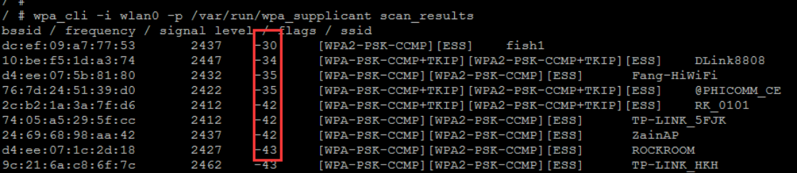
Vergleichen Sie die Zahl gefundener Hotspots mit der ungefähren Routeranzahl vor Ort und dem Smartphone-Scan. Unterstützt das Modul kein 5-GHz-Wi-Fi, vergleichen Sie nur 2,4 GHz. Prüfen Sie die Signalstärke des nächsten Routers. Ist er sehr nah, das Signal aber schwach (typisch gut: -20 bis -50; schwächer, aber akzeptabel: -50 bis -70; schlecht: -70 bis -90), prüfen Sie Antennenanschluss und RF-Konformität des Moduls. Siehe Wi-Fi-/BT-Hardware-RF-Spezifikationen.
4.1.3 Mit dem Router verbinden
Konfigurationsdatei ändern
# Add network configuration item in wpa_supplicant.conf
network={
    ssid="WiFi-AP"        # Wi-Fi Name
    psk="12345678"        # Wi-Fi Password
    key_mgmt=WPA-PSK      # Encryption configuration, change to key_mgmt=NONE for
no encryption
}

# Reload the above configuration for the wpa_supplicant process with the
following command:
wpa_cli -i wlan0 -p /var/run/wpa_supplicant reconfigure

# Initiate connection:
wpa_cli -i wlan0 -p /var/run/wpa_supplicant reconnect

# Connection Information
wpa_cli -i wlan0 -p /var/run/wpa_supplicant status
bssid=04:42:1a:b4:e7:7c
freq=5805
ssid=wwc3
id=0
mode=station
wifi_generation=6
pairwise_cipher=CCMP
group_cipher=CCMP
key_mgmt=SAE
pmf=2
mgmt_group_cipher=BIP
sae_group=19
sae_h2e=0
sae_pk=0
wpa_state=COMPLETED
ip_address=192.168.50.169
address=d4:9c:dd:f5:52:c4
uuid=47ed7266-da34-5c0b-884a-4fcc17648d87
ieee80211ac=1
4.2 Wi-Fi-AP-Hotspot prüfen
Das SDK enthält die benötigten Programme. softapDemo apName startet einen Hotspot namens apName, standardmäßig unverschlüsselt. Quellcode- und Builddateipfade:
/external/softapDemo/src/main.c
buildroot/package/rockchip/softap/Config.in softap.mk
make softap-dirclean
make softap
Fehlt der softapDemo-Quellcode, laden Sie ihn von folgender Adresse ins Verzeichnis external:
https://github.com/rockchip-linux/softapServer
Realtek: softap verwendet p2p0, das durch die Kerneltreiberkonfiguration erzeugt wird. Fehlt p2p0, prüfen Sie folgende Konfiguration:
+++ b/drivers/net/wireless/rockchip_wlan/rtl8xxx/Makefile
@@ -1593,7 +1593,7 @@ endif
ifeq ($(CONFIG_PLATFORM_ARM_RK3188), y)
EXTRA_CFLAGS += -DCONFIG_PLATFORM_ANDROID
+EXTRA_CFLAGS += -DCONFIG_CONCURRENT_MODE
AMPAK/Azurewave: softap verwendet wlan1. Erzeugen Sie den Knoten mit iw phy0 interface add wlan1 type managed. Fehlersuche und Anpassung:
// Here you can add encryption, modify IP addresses, and DNS, etc., which can be
modified by yourself
int wlan_accesspoint_start(const char* ssid, const char* password)
{
    // Create softap hotspot configuration
    create_hostapd_file(ssid, password);
    // softap_name: wlan1/p2p0
    sprintf(cmdline, "ifconfig %s up", softap_name);
    // Set custom IP address
    sprintf(cmdline, "ifconfig %s 192.168.88.1 netmask 255.255.255.0",
softap_name);

    // Create a configuration file for the DHCP address pool
    creat_dnsmasq_file();
    int dnsmasq_pid = get_dnsmasq_pid();
    if (dnsmasq_pid != 0) {
        memset(cmdline, 0, sizeof(cmdline));
        sprintf(cmdline, "kill %d", dnsmasq_pid);
        console_run(cmdline);
    }
    memset(cmdline, 0, sizeof(cmdline));
    // Use dnsmasq as a DHCP server to assign IP addresses to devices
    sprintf(cmdline, "dnsmasq -C %s --interface=%s", DNSMASQ_CONF_DIR,
softap_name);
    console_run(cmdline);

    memset(cmdline, 0, sizeof(cmdline));
    // Start softap hotspot mode
    sprintf(cmdline, "hostapd %s &", HOSTAPD_CONF_DIR);
    console_run(cmdline);
    return 1;
}

// Create a DHCP configuration file, which must be consistent with your custom IP
address, otherwise, it will cause the mobile phone to be unable to obtain an IP
bool creat_dnsmasq_file()
{
    FILE* fp;
    fp = fopen(DNSMASQ_CONF_DIR, "wt+");
    if (fp != 0) {
        fputs("user=root\n", fp);
        fputs("listen-address=", fp);
        fputs(SOFTAP_INTERFACE_STATIC_IP, fp);
        fputs("\n", fp);
        fputs("dhcp-range=192.168.88.50,192.168.88.150\n", fp);
        fputs("server=/google/8.8.8.8\n", fp);
        fclose(fp);
        return true;
    }
    DEBUG_ERR("---open dnsmasq configuration file failed!!---");
    return false;
}

// Create an AP hotspot configuration file, which can be consulted with the Wi-Fi
manufacturer, and the parameters here are greatly related to the chip
specifications
int create_hostapd_file(const char* name, const char* password)
{
    FILE* fp;
    char cmdline[256] = {0};
    fp = fopen(HOSTAPD_CONF_DIR, "wt+");

    if (fp != 0) {
        sprintf(cmdline, "interface=%s\n", softap_name);
        fputs(cmdline, fp);
        fputs("ctrl_interface=/var/run/hostapd\n", fp);
        fputs("driver=nl80211\n", fp);
        fputs("ssid=", fp);
        fputs(name, fp);
        fputs("\n", fp);
        fputs("channel=6\n", fp);  // Channel setting
        fputs("hw_mode=g\n", fp);  // 2.4/5G configuration
        fputs("ieee80211n=1\n", fp);
        fputs("ignore_broadcast_ssid=0\n", fp);
#if 0  // If encryption is chosen, modify here
        fputs("auth_algs=1\n", fp);
        fputs("wpa=3\n", fp);
        fputs("wpa_passphrase=", fp);
        fputs(password, fp);
        fputs("\n", fp);
        fputs("wpa_key_mgmt=WPA-PSK\n", fp);
        fputs("wpa_pairwise=TKIP\n", fp);
        fputs("rsn_pairwise=CCMP", fp);
#endif
        fclose(fp);
        return 0;
    }
    return -1;
}

int main(int argc, char **argv)
    // According to the Wi-Fi model, set the corresponding hotspot interface. The
4.4 kernel can automatically obtain the Wi-Fi model through the
"/sys/class/rkwifi/chip" node,
    // but the kernel version 4.19 and later does not have this node, and the Wi-
Fi model can be determined in the following way
    // AMPAK/Azurewave: Check for the directory sys/bus/sdio/drivers/bcmsdh_sdmmc
    // Realtek: Check for the directory sys/bus/sdio/drivers/rtl8723ds
    if (!strncmp(wifi_type, "RTL", 3))
        strcpy(softap_name, "p2p0"); // Realtek uses p2p0
    else
        strcpy(softap_name, "wlan1"); // AMPAK/Azurewave uses wlan1

    ... ...
    if (!strncmp(wifi_type, "RTL", 3)) {
        // Realtek module automatically generates the p2p0 node after enabling
coexistence mode
        console_run("ifconfig p2p0 down");
        console_run("rm -rf /userdata/bin/p2p0");
        wlan_accesspoint_start(apName, NULL);
    } else {
        console_run("ifconfig wlan1 down");
        console_run("rm -rf /userdata/bin/wlan1");
        console_run("iw dev wlan1 del");
        console_run("ifconfig wlan0 up");
        // AP module needs the iw command to generate the wlan1 node for softap
use
        console_run("iw phy0 interface add wlan1 type managed");
        wlan_accesspoint_start(apName, NULL);
    }
Nach dem Befehl sollte der AP in den Wi-Fi-Einstellungen des Telefons erscheinen. Andernfalls prüfen Sie zuerst die genannten Konfigurationsdateien, dann wlan1 oder p2p0 in ifconfig und den erfolgreichen Start von hostapd/dnsmasq.
4.3 BT-Funktionstest
Prüfen Sie zunächst DTS/Buildroot gemäß 2/3/7.2. Dieser Abschnitt behandelt zwei verbreitete BT-Modultypen. Bei korrekter Konfiguration entsteht bt_pcba_test, in neueren SDKs bt_init.sh. REALTEK-Modul:
# UART Interface:
/ # cat usr/bin/bt_pcba_test (bt_init.sh)
#!/bin/sh

killall rtk_hciattach

echo 0 > /sys/class/rfkill/rfkill0/state   # Power down
echo 0 > /proc/bluetooth/sleep/btwrite
sleep 1
echo 1 > /sys/class/rfkill/rfkill0/state   # Power up
echo 1 > /proc/bluetooth/sleep/btwrite
sleep 1
insmod /usr/lib/modules/hci_uart.ko           # REALTEK module requires loading
the UART driver
rtk_hciattach -n -s 115200 /dev/ttyS4 rtk_h5 &   # The blue reference indicates
which UART port the Bluetooth is using

# Note: Kill the rtk_hciattach process before starting the test each time.

# Note: For USB interface Bluetooth, there is no sh script. Execute the following
manually:
echo 0 > /sys/class/rfkill/rfkill0/state   # Power down
echo 0 > /proc/bluetooth/sleep/btwrite
sleep 1
echo 1 > /sys/class/rfkill/rfkill0/state   # Power up
echo 1 > /proc/bluetooth/sleep/btwrite
sleep 1
insmod /usr/lib/modules/rtk_btusb.ko          # REALTEK module requires loading
the USB driver
AMPAK-/Azurewave-Modul
/ # cat usr/bin/bt_pcba_test (bt_init.sh)
#!/bin/sh

killall brcm_patchram_plus1

echo 0 > /sys/class/rfkill/rfkill0/state  # Power down
echo 0 > /proc/bluetooth/sleep/btwrite
sleep 2
echo 1 > /sys/class/rfkill/rfkill0/state  # Power up
echo 1 > /proc/bluetooth/sleep/btwrite
sleep 2

brcm_patchram_plus1 --bd_addr_rand --enable_hci --no2bytes --
use_baudrate_for_download --tosleep 200000 --baudrate 1500000 --patchram
/system/etc/firmware/bcm43438a1.hcd /dev/ttyS4 &

# Note: Kill the brcm_patchram_plus1 process before starting the test each time.
Bcm44338a1.hcd bezeichnet die Firmware des BT-Modells, /dev/ttyS4 den verwendeten UART. rtk_hciattach, hci_uart.ko und bcm43438a1.hcd entstehen nur bei korrekter Wi-Fi-/BT-Modulauswahl in Buildroot gemäß Abschnitt 2. Fehlen Dateien, prüfen Sie die Konfiguration (Abschnitt 3). Führen Sie nach dem Skript die folgenden Befehle aus. Fehlt hciconfig, aktivieren Sie BR2_PACKAGE_BLUEZ5_UTILS in Buildroot, bauen und aktualisieren Sie das System. Führen Sie hciconfig hci0 up und hciconfig –a aus. Normalerweise erscheint folgende Ausgabe:
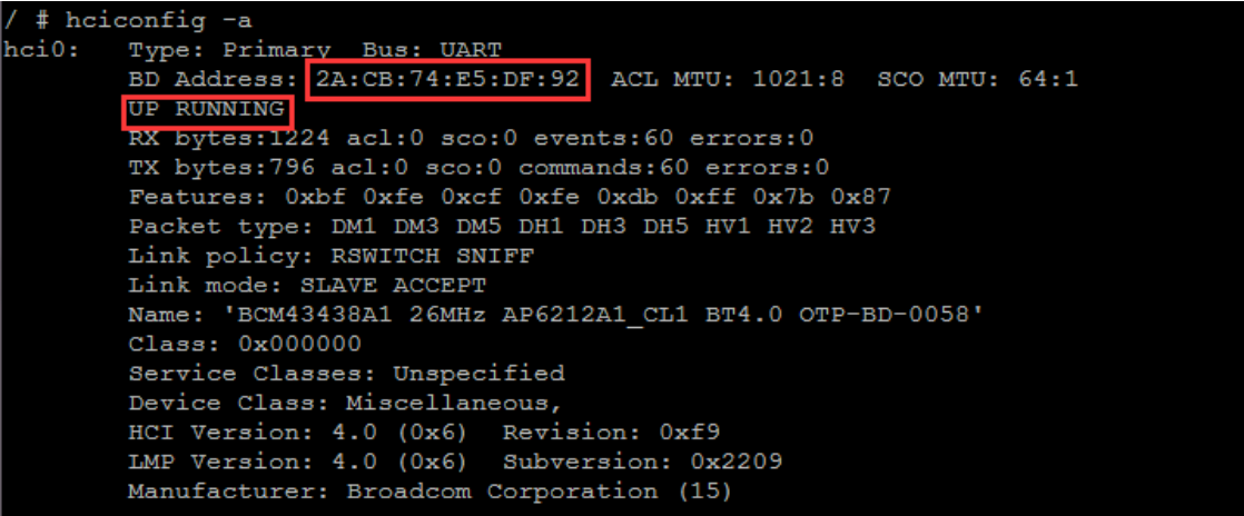
BT-Scan: hcitool scan
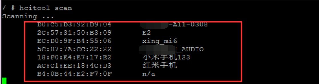
Bei Fehlern siehe die Fehlersuche in Abschnitt 7.2.
4.4 Aufwecken über Wi-Fi (WoL)
Wi-Fi unterstützt Netzwerkaufwecken: Ein mit einem AP verbundenes Gerät mit IP-Adresse kann nach dem Einschlafen durch ein Funkpaket, etwa Ping, geweckt werden. Grundsätzlich kann jedes an das Gerät gerichtete Netzwerkpaket aufwecken. Ergänzen Sie wpa_supplicant.conf:
wpa_supplicant.conf
ctrl_interface=/var/run/wpa_supplicant
update_config=1
ap_scan=1
+wowlan_triggers=any # Add this configuration
Prüfen Sie bei Realtek-Wi-Fi folgende Einstellungen im Treiber-Makefile:
kernel/drivers/net/wireless/rockchip_wlan/rtl8xxx/Makefile
+CONFIG_WOWLAN = y
+CONFIG_GPIO_WAKEUP = y
DTS: Stellen Sie anhand des Schaltplans sicher, dass WIFI_WAKE_HOST beziehungsweise WL_HOST_WAKE mit dem SoC verbunden ist, und prüfen Sie folgende Konfiguration:
WIFI,host_wake_irq = <&gpio0 RK_PA0 GPIO_ACTIVE_HIGH>;
Standby von System und Wi-Fi testen:
dhd_priv setsuspendmode 1  # Only for AMPAK Azurewave modules, Realtek does not
require this command
echo mem > /sys/power/state
Geräte im selben LAN können nun Ping senden; normalerweise wacht das System dadurch auf. Stellen Sie anschließend den normalen Wi-Fi-Betrieb wieder her:
dhd_priv setsuspendmode 0 # Only for AMPAK Azurewave modules, Realtek does not
require this command
Fehlersuche: Bleibt das Aufwecken aus, prüfen Sie Wake-Pin, Pegel und ob der 32,768-kHz-Takt abgeschaltet wird.
4.5 Wi-Fi-MONITOR-Modus
AMPAK-/Azurewave-Wi-Fi
# Set the monitor channel:
dhd_priv channel 6  // channel numbers

# Enable monitor mode:
dhd_priv monitor 1

# Disable monitor mode:
dhd_priv monitor 0
Realtek-Wi-Fi
# The driver Makefile needs to enable:
+ CONFIG_WIFI_MONITOR = y

# Bring up wlan0 and bring down p2p0
ifconfig wlan0 up
ifconfig p2p0 down

# Enable monitor mode
iwconfig wlan0 mode monitor
or
iw dev wlan0 set type monitor

# Switch to a specific channel
echo "<chan> 0 0" > /proc/net/<rtk_module>/wlan0/monitor // <rtk_module> is the
Realtek Wi-Fi module name, such as rtl8812au, rtl8188eu, etc.
4.6 Wi-Fi-P2P-Prüfung
# Create a new configuration file: p2p_supplicant.conf
ctrl_interface=/var/run/wpa_supplicant
update_config=1
device_name=p2p_device_name
device_type=10-0050F204-5
config_methods=display push_button keypad virtual_push_button physical_display
p2p_add_cli_chan=1
pmf=1
# Start: (kill the previous one first)
wpa_supplicant -B -i wlan0 -c /tmp/p2p_supplicant.conf
wpa_cli
> p2p_find
>

# At this point, open the P2P on the mobile device and you can search for the
device name specified above as device_name=p2p_device_name and click to connect

# At this point, the device side will display // Below is the test mobile device
> <3>P2P-PROV-DISC-PBC-REQ 26:31:54:8e:14:e7 p2p_dev_addr=26:31:54:8e:14:e7
pri_dev_type=10-0050F204-5 name='www' config_methods=0x188 dev_capab=0x25
group_capab=0x0

# The device side responds and sends a connection command, make sure the MAC
address matches the one above
>p2p_connect 26:31:54:8e:14:e7 pbc go_intent=1

> p2p_connect 26:31:54:8e:14:e7 pbc go_intent=1
OK
<3>P2P-FIND-STOPPED
<3>P2P-GO-NEG-SUCCESS role=client freq=5200 ht40=0 peer_dev=26:31:54:8e:14:e7
peer_iface=26:31:54:8e:94:e7 wps_method=PBC
<3>P2P-GROUP-FORMATION-SUCCESS
<3>P2P-GROUP-STARTED p2p-wlan0-2 client ssid="DIRECT-24-www" freq=5200
psk=3d67671b71f7a171118c1ace34ae5e4bcc8e17394394e258be91f55b7ab63748
go_dev_addr=26:31:54:8e:14:e7 [PERSISTENT]
> # At this point, the connection is successful
> quit

ifconfig
p2p-wlan0-2 Link encap:Ethernet  HWaddr 82:C5:F2:2E:7F:89
          inet addr:192.168.49.220  Bcast:192.168.49.255  Mask:255.255.255.0
          UP BROADCAST RUNNING MULTICAST  MTU:1500   Metric:1
          RX packets:470 errors:0 dropped:0 overruns:0 frame:0
          TX packets:344 errors:0 dropped:0 overruns:0 carrier:0
          collisions:0 txqueuelen:1000
          RX bytes:71779 (70.0 KiB)  TX bytes:33829 (33.0 KiB)
# It can be seen that the device is connected to the mobile phone, and if they
can ping each other, it indicates that it is normal.
4.7 Netzwerkschnittstellen überbrücken
Szenario: wlan0 verbindet sich mit einem erreichbaren AP; wlan1 oder p2p0 wird gemäß Abschnitt 4.2 als Hotspot gestartet, damit ein Smartphone darüber ins Internet gelangt. Aktivieren Sie folgende Kernelkonfiguration:
+CONFIG_NETFILTER=y
+CONFIG_NF_CONNTRACK=y
+CONFIG_NF_TABLES=y
+CONFIG_NF_TABLES_INET=y
+CONFIG_NF_CONNTRACK_IPV4=y
+CONFIG_IP_NF_IPTABLES=y
+CONFIG_IP_NF_NAT=y
+CONFIG_IP_NF_TARGET_MASQUERADE=y
+CONFIG_BRIDGE=y
Führen Sie die folgenden beiden Befehle mit der beim softap-Start konfigurierten IP-Adresse aus:
iptables -t nat -A POSTROUTING -s 192.168.43.0/24 -o wlan0 -j MASQUERADE
echo "1" > /proc/sys/net/ipv4/ip_forward
4.8 Wi-Fi-/BT-Hardware-RF-Spezifikationen
4.8.1 Testpunkte
4.8.2 Wi-Fi-/BT-Teil
Beispielsweise Sendeleistung, EVM, Quarzfrequenzabweichung und Empfangsempfindlichkeit. Beispiel für b/g/n/ac:
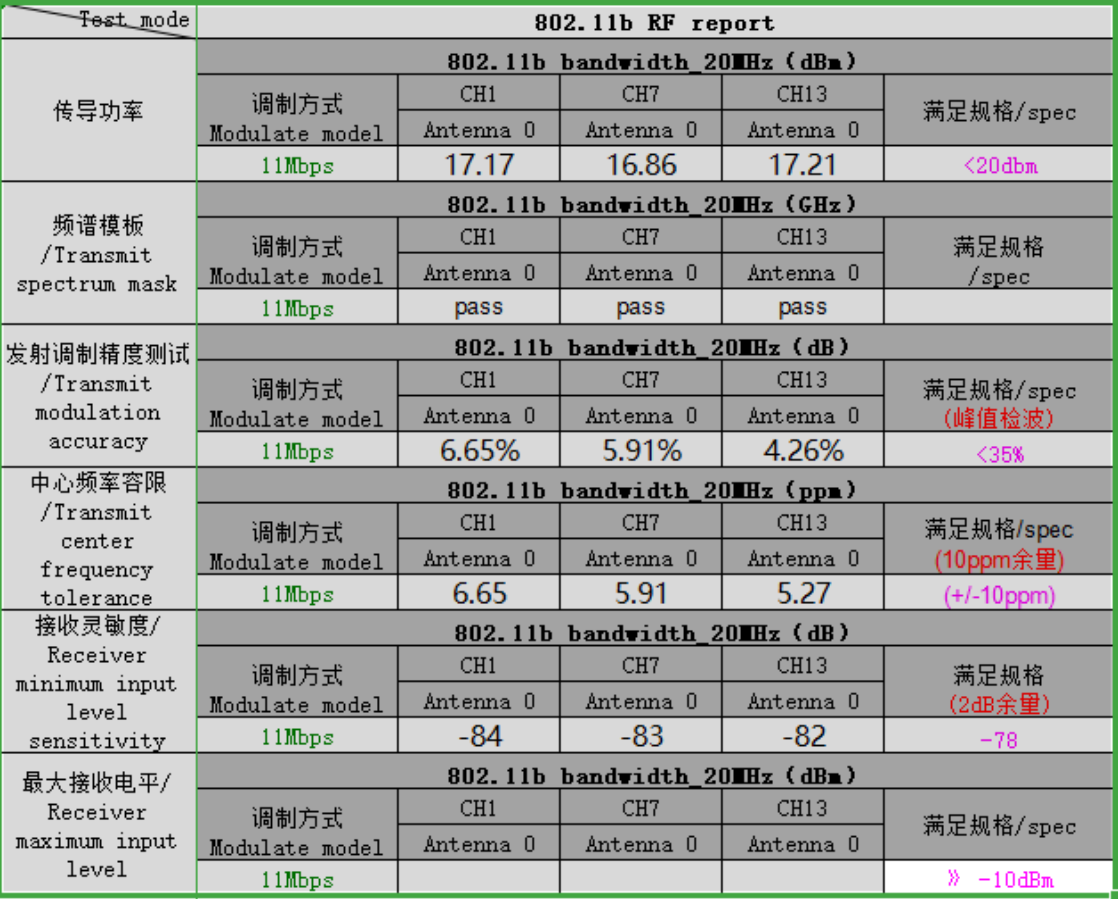
802.11b / 20 MHz / 11 Mbps / Antenna 0
| Messgröße | Einheit | CH1 | CH7 | CH13 | Vorgabe |
|---|---|---|---|---|---|
| Leitungsgebundene Leistung | dBm | 17.17 | 16.86 | 17.21 | <20 dBm |
| Sendespektrummaske | GHz | bestanden | bestanden | bestanden | |
| Sendemodulationsgenauigkeit | dB / % | 6.65% | 5.91% | 4.26% | <35%; Spitzenerkennung |
| Mittenfrequenztoleranz | ppm | 6.65 | 5.91 | 5.27 | ±10 ppm; 10 ppm Reserve |
| Minimale Empfangsempfindlichkeit | dB | -84 | -83 | -82 | -78; 2 dB Reserve |
| Maximaler Empfangseingangspegel | dBm | » -10 dBm |
4.8.3 Antenne
Passive S11- und aktive OTA-Tests der Wi-Fi-Antenne im Gerät. Beispiel:

Wi-Fi 2G TRP
| Modus | Kanal | Frequenz (MHz) | Mittlere Sendeleistung (dBm) | Mittlere Empfindlichkeit (dBm) |
|---|---|---|---|---|
| 80211b: 11MBps | 1 | 2412 | 11.12 | -80.8 |
| 80211b: 11MBps | 7 | 2442 | 14.39 | -80.62 |
| 80211b: 11MBps | 13 | 2472 | 13.79 | -80.54 |
| 80211g: 54MBps | 1 | 2412 | 12.4 | -67.25 |
| 80211g: 54MBps | 7 | 2442 | 15.07 | -66.49 |
| 80211g: 54MBps | 13 | 2472 | 14.45 | -65.66 |
Fassen Sie die genannten Tests in einem formellen Bericht zusammen.
4.8.4 Testwerkzeuge und -methoden
Die nachfolgend genannten PDF-/TXT-Dateien liegen unter docs/linux/wifibt. Fehlen professionelle Messgeräte oder bestehen Fragen, wenden Sie sich an den Modulhersteller. Für icomm-semi/altobeam/AIC und weitere Plattformen beziehen Sie Werkzeuge und Verfahren vom jeweiligen Modul- oder Chiphersteller.
4.8.4.1 Realtek-Tests
Unterschieden werden gewöhnlich COB und Module. Module werden vom Hersteller umfassend geprüft und normalerweise mit Kalibrierdaten in efuse geliefert; Kunden müssen die Leistungswerte verifizieren. Bei COB werden Wi-Fi-Außenbeschaltung und Bauteile selbst entworfen. Deshalb ist eine vollständige RF-Kalibrierung mit Realtek erforderlich; die Daten werden in efuse geschrieben oder über den Treiber geladen. Einzelheiten beim Modulhersteller erfragen. Wi-Fi-Tests:
Refer to the Quick_Start_Guide_V6.txt, pay special attention to the command
iwpriv which should be uniformly replaced with rtwpriv.
BT-Tests: Siehe „MP tool user guide for linux20180319.pdf“; konkrete Verfahren beim Modulhersteller oder Lieferanten erfragen. Für die Messung ist spezielle Bluetooth-Testfirmware des Herstellers erforderlich, die im vorgegebenen Verzeichnis abgelegt werden muss.
# Note: Before performing the test, please turn on the BT power
echo 0 > sys/class/rfkill/rfkill0/state
echo 0 > /proc/bluetooth/sleep/btwrite
sleep 1
echo 1 > sys/class/rfkill/rfkill0/state
echo 1 > /proc/bluetooth/sleep/btwrite
# Special attention: The rtk_hciattach process should not run, if it does, please
terminate it with killall rtk_hciattach

///////////
/ #
/ # rtlbtmp
:::::::::::::::::::::::::::::::::::::::::::::::::
:::::::: Bluetooth MP Test Tool Starting ::::::::

>
>
>enable uart:/dev/ttyS4   # Note: ttySX corresponds to the actual hardware
connected uart port
>
>> > enable[Success:0]
4.8.4.2 Synopsys-/Infineon-Chips testen
Wi-Fi-Tests: Zuerst die Testfirmware installieren. Jedes AP-Modul benötigt eine passende Testfirmware, beispielsweise:
AP6236 -> fw_bcm43436b0_mfg.bin
AP6212A -> fw_bcm43438a1_mfg.bin
fw_bcmxxx_mfg.bin und APxxxx müssen zum Modulmodell passen, sonst ist kein Test möglich. Prüfen Sie zuerst die passende Firmware und beziehen Sie fehlende Dateien vom Hersteller. Neuere SDKs enthalten Testfirmware für unterstützte Modelle; das integrierte Skript schaltet Wi-Fi direkt in den RF-Testmodus.
external\rkwifibt\wifi_ap6xxx_rftest.sh
#!/bin/sh
killall ipc-daemon netserver connmand wpa_supplicant

# Reset
echo 0 > /sys/class/rfkill/rfkill0/state
sleep 1
echo 1 > /sys/class/rfkill/rfkill1/state
sleep 1

# Set to update the test firmware
echo /vendor/etc/firmware/fw_bcmdhd_mfg.bin >
/sys/module/bcmdhd/parameters/firmware_path
sleep 1

# Restart wlan0
ifconfig wlan0 down
ifconfig wlan0 up
sleep 1
# Confirm whether it has entered the test mode
echo "wl ver"
wl ver
Ältere SDKs enthalten keine Testfirmware; verwenden Sie folgendes Beispiel:
# AP6236
# Push fw_bcm43436b0_mfg.bin to the data or other writable partition, then
execute the following commands: (Note the path below)
mount --bind /data/fw_bcm43436b0_mfg.bin /system/etc/firmware/fw_bcm43436b0.bin
ifconfig wlan0 down
ifconfig wlan0 up
wl ver

# CYW43438
echo /data/cyw43438-7.46.58.25-mfgtest.bin >
/sys/module/cywdhd/parameters/firmware_path
ifconfig wlan0 down
ifconfig wlan0 up
wl ver
Bei korrekter Einrichtung gibt wl ver eine Zeichenfolge mit „WL_TEST“ aus und bestätigt damit den Testmodus. Ausführliche Testanleitung:
Wi-Fi RF Test Commands for Linux-v03.pdf
Bluetooth-Tests: Führen Sie nach dem integrierten bt_init.sh-Skript (Abschnitt 3.3) Folgendes aus. Fehlt hciconfig, aktivieren Sie BR2_PACKAGE_BLUEZ5_UTILS in Buildroot, bauen und aktualisieren Sie das Testsystem.
hciconfig hci0 up
hciconfig -a
Ein hci0-Knoten zeigt die abgeschlossene Initialisierung an. Fehlt er, kommen zwei Ursachen infrage:
- Fehlerhaftes Bluetooth-DTS, Hardwarefehler oder falscher UART verhindern die Initialisierung.
- Bluetooth-Firmware falsch konfiguriert oder nicht vorhanden. Zur Fehlersuche siehe die BT-Abschnitte 2/3. Konkrete Testanleitungen:
BT RF Test Commands for Linux-v05.pdf #The test steps 1/2 are already executed in
the script, no need to execute them again
4.9 Wi-Fi-Leistungstests
Beachten Sie bei iperf zwei Einflussfaktoren. Schließen Sie vor Leistungsmessungen Wi-Fi-RF- und Antennen-OTA-Tests mit normalen Werten ab; andernfalls sind die Ergebnisse wenig aussagekräftig. Bei starken Schwankungen testen Sie an einem störungsarmen Ort, etwa im Freien oder Keller, vorzugsweise in einer Schirmkammer. Wegen hoher Störpegel in offenen Umgebungen wird die Kammer empfohlen. Prüfen Sie zunächst die normale AP-Verbindung und den IP-Bezug. Messen Sie Durchsatz, Stabilität und Schwankungen. Testen Sie niedrige, mittlere und hohe Routerkanäle, beispielsweise 1/6/11. Befehle stehen in „iPerf - iPerf3 and iPerf2 user documentation“, iperf2 / iperf3 (es.net). Aktivieren Sie für die Platine BR2_PACKAGE_IPERF = y und BR2_PACKAGE_IPERF3 = y in Buildroot.
5. Wi-Fi-/BT-Fehlersuche
Wichtig: Immer zuerst das Protokoll prüfen und Fehler daraus ableiten! Wi-Fi-/BT-Probleme fallen gewöhnlich in drei Gruppen: SDIO-/USB-/PCIE-Gerät nicht erkannt; SDIO-Karte erkannt, aber Firmwareladen fehlgeschlagen; Leistungsprobleme wie keine Verbindung, wenige Scanergebnisse oder sporadische Abbrüche.
5.1 Überblick zur Wi-Fi-Erkennung
SDIO: Beim Start erkennt das MMC-Framework des Kernels die Karte. Zunächst wertet es den GPIO der reset-gopios-Eigenschaft des DTS-Knotens sdio_pwrseq aus; dies ist WL_REG_ON, das auf High gesetzt wird. Danach folgen Initialisierungsbefehle über SDIO_CLK/CMD/DATA. Anfangs werden 400/300/200K verwendet, um Grunddaten zu ermitteln: SDIO2.0 (maximal CLK 50M) oder 3.0 (208M), Vier- oder Ein-Leitungs-Unterstützung usw. Anschließend steigt SDIO_CLK entsprechend den Fähigkeiten auf 50M/150M und die Grundinitialisierung endet. Protokoll:
# Note that the number 0 in mmc0 is not fixed, it could also be 0/1/2; ff4a0000:
represents the address of the controller, which is also different from platforms
# Parse the mmc-pwrseq node in the dts, to obtain WL_REG_ON
dwmmc_rockchip ff4a0000.dwmmc: allocated mmc-pwrseq
# Low-frequency initialization
mmc_host mmc0: Bus speed (slot 0) = 400000Hz (... actual 400000HZ div = 0)
# High-frequency operation mode
mmc_host mmc0: Bus speed (slot 0) = 50000000Hz (... actual 50000000HZ div = 0)
# SDIO 2.0
mmc0: new high speed SDIO card at address 0001
# SDIO 3.0
mmcx: new ultra high speed SDR104 SDIO card at address 0001
USB/PCIE: Die Erkennung ist komplexer; siehe die entsprechenden Dokumente im doc-Verzeichnis. Nach erfolgreicher USB-Erkennung zeigt lsusb Informationen wie die folgenden:
Bus 001 Device 002: ID 0bda:f179 Realtek Semiconductor Corp. RTL8188FTV
802.11b/g/n 1T1R 2.4G WLAN Adapter
Prüfen Sie USB alternativ mit dmesg | grep usb. Nach erfolgreicher PCIE-Erkennung zeigt lspci:
0002:21:00.0 Network controller: Broadcom Inc. and subsidiaries Device 449d (rev
02)
Alle genannten Erkennungsverfahren laufen beim Systemstart. Der Wi-Fi-Treiber wird erst nach erfolgreicher Erkennung des passenden Geräts korrekt geladen!
5.2 Wi-Fi-Fehlersuche
Bei SDIO-Wi-Fi gibt es gewöhnlich zwei Fälle. Suchen Sie zuerst die folgenden Kernelmeldungen. Fehlen sie, wurde die SDIO-Karte nicht erkannt; siehe Abschnitt 7.1.1.
mmc0: new high speed SDIO card at address 0001
# or
mmcx: new ultra high speed SDR104 SDIO card at address 0001
SDIO wird laut Protokoll korrekt erkannt, aber wlan0 fehlt oder lässt sich nicht aktivieren.
5.2.1 Wi-Fi-Störung: SDIO nicht erkannt
Prüfen Sie zunächst unbedingt DTS/KERNEL aus Kapitel 2 erneut sorgfältig! Gehen Sie anschließend anhand des Kernelprotokolls der Reihe nach vor:
5.2.1.1 Spannungen messen
Messen Sie Pegel und CLK-Frequenz an den markierten Pins. SDIO 3.0 erfordert unbedingt 1,8 V.
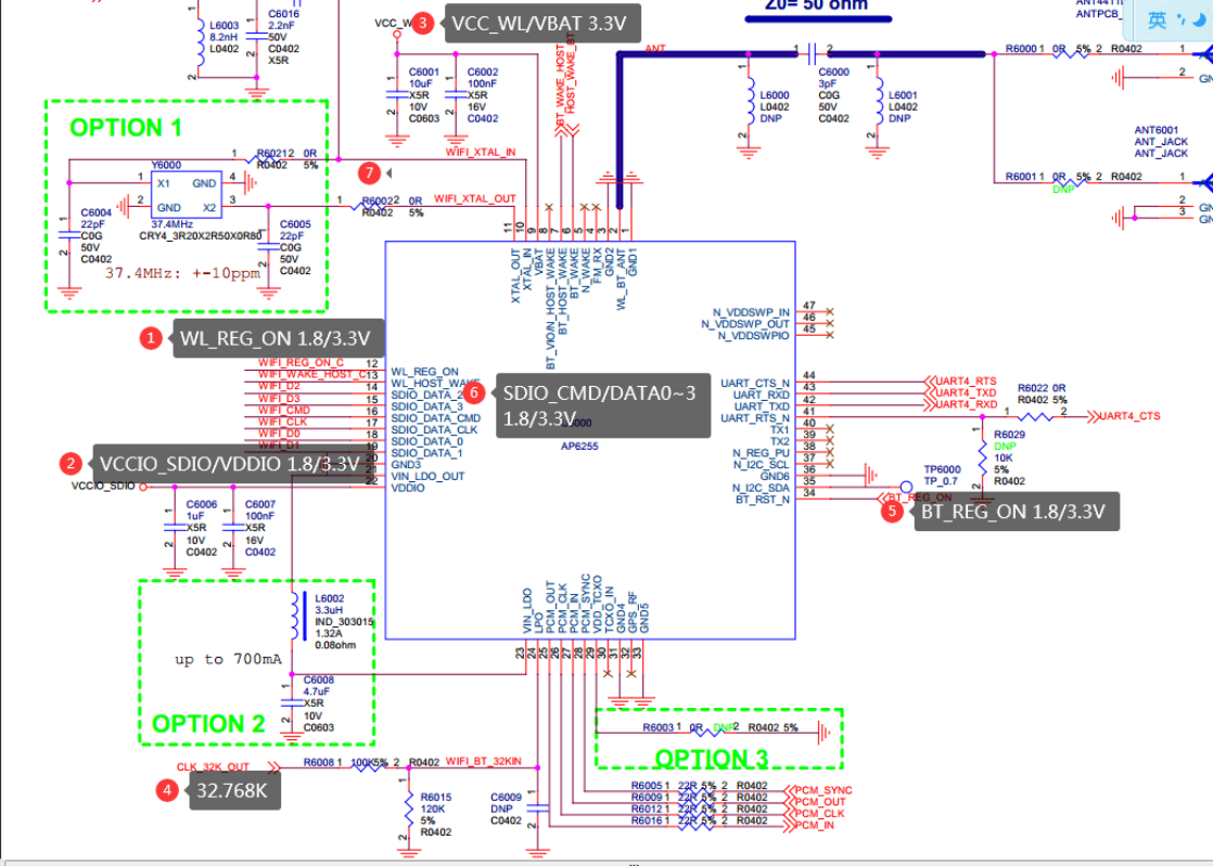
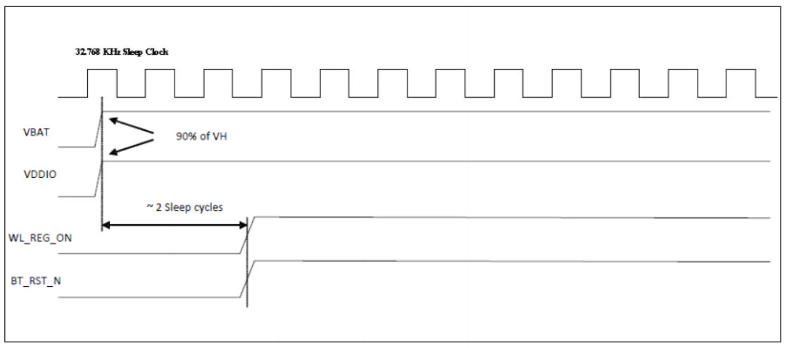
Messen Sie VBAT/VDDIO/WL_REG_ON mit dem Oszilloskop und prüfen Sie folgende Timinganforderungen:
5.2.1.2 Zeitlicher Ablauf
Nachfolgend stehen AMPAK-Anforderungen. Prüfen Sie das Timingdiagramm des tatsächlich verwendeten Moduls, insbesondere VDDIO.
5.2.1.3 Falsches WL_REG_ON im DTS
Der Wi-Fi-Enable-Pin wird nicht High. Prüfen Sie mit dem Oszilloskop Pegelwechsel und Amplitude von 1,8/3,3 V. Wiederholte High-/Low-Wechsel sind normal, da SDIO mehrfach initialisiert wird. Bei Erfolg bleibt WL_REG_ON High, bei Fehler wird es Low. Dauerhaft Low deutet auf falsches DTS hin. Wird das Gerät bei direkt hardwareseitig erzwungenem High erkannt, spricht dies ebenfalls für falsches WL_REG_ON im DTS.
mmcX: Bus speed (slot 0) = 300000Hz (slot req 300000Hz, actual 300000HZ div =
0)
mmcX: Bus speed (slot 0) = 200000Hz (slot req 200000Hz, actual 200000HZ div =
0)
mmcX: Bus speed (slot 0) = 100000Hz (slot req 100000Hz, actual 100000HZ div =
0)
5.2.1.4 Falsches WL_REG_ON im DTS
5.2.1.5 VDDIO-/SDIO-/IO-Spannungsdomäne
VDDIO an PIN12 muss 3,3/1,8 V betragen; SDIO_CMD/SDIO_DATA0~3 müssen entsprechend ebenfalls 3,3 oder 1,8 V haben. Prüfen Sie, ob VDDIO zur DTS-Spannungsdomänenkonfiguration passt.
5.2.1.6 Kein SDIO_CLK-Signal
Falsche IO-Spannungsdomäneneinstellungen können CLK verhindern. Prüfen Sie einen vorhandenen CLK-Pull-up und testen Sie ohne ihn. Stellen Sie zum Erfassen des CLK-Signals den Oszilloskoptrigger ein.
5.2.1.7 Unzureichende Versorgung oder starke Spannungsschwankungen
VCC_WL/VBAT/VDDIO_SDIO: unzureichende Versorgung oder starke Spannungsschwankungen.
# Realtek Modules
RTL871X: ### rtw_hal_ops_check - Error : Please hook HalFunc.read_chip_version
###
RTL871X: ### rtw_hal_ops_check - Error : Please hook HalFunc.init_default_value
###
5.2.1.8 32.768K
Externer Takt: LPO-Signaleigenschaften
| Parameter | Spezifikation | Einheiten |
|---|---|---|
| Nominelle Eingangsfrequenz | 32.768 | kHz |
| Frequenzgenauigkeit | ± 30 | ppm |
| Tastgrad | 30 - 70 | % |
| Eingangssignalamplitude | 400 bis 1800 | mV, Spitze-Spitze |
| Signaltyp | Rechteck | - |
| Eingangsimpedanz | >100k <5 | Ω pF |
| Taktjitter (integriert über 300 Hz – 15 kHz) | <1 | Hz |
| Ausgangsspannung bei High-Pegel | 0.7Vio - Vio | V |
CLK_32K_OUT: Das 32,768-kHz-Signal fehlt oder seine Genauigkeit erfüllt die Anforderungen der obigen Tabelle nicht!
# For AMPAK/Azurewave modules, the abnormal log for 32k:
[11.068180] dhdsdio_htclk: HT Avail timeout (1000000): clkctl 0x50
[11.074372] dhd_bus_init: clock state is wrong. state = 1
[12.078468] dhdsdio_htclk: HT Avail timeout (1000000): clkctl 0x50
[12.086051] dhd_net_bus_devreset: dhd_bus_devreset: -1
5.2.1.9 Ungeeignetes PCB-Routing, Kapazitäten oder Induktivitäten
SDIO_CLK/CMD/DATAX: Fehlerhaftes PCB-Routing, ungeeignete Kondensatoren/Induktivitäten, schlechte Kontakte oder Lötstellen können Initialisierungsfehler oder Probleme bei hohen Frequenzen verursachen. Senken Sie zur Prüfung max-frequency im &sdio-Knoten. Hilft dies, müssen Hardwareentwickler die Signale messen und die CLK/CMD/DATA-Timinganforderungen des Wi-Fi-Moduldatenblatts prüfen. Frequenzänderung:
&sdio {
+  max-frequency = <10000000>;   # Modify here to limit the frequency
5.2.1.10 io_domain-Konfiguration
Prüfen Sie, ob die Spannungen von Wi-Fi und SDIO-Hostcontroller übereinstimmen und die Softwarekonfiguration von io_domain zur Hardware passt (Abschnitt 2.2.3).
// Abnormal log 1
mmc_host mmc1: Bus speed(slot0)=100000000Hz(slotreq 100000000Hz,actual
100000000HZ div=0)
dwmmc_rockchip ff0d0000.dwmmc: All phases bad!
mmc1: tuning execution failed
mmc1: error -5 whilst initialising SDIO card

// Abnormal log 2, such as logs for data communication exceptions like firmware
download failure:
sdioh_buffer_tofrom_bus: TX FAILED ede95000, addr=0x08000, pkt_len=1968, ERR=-84
_dhdsdio_download_firmware: dongle image file download failed
dhd_bus_devreset Failed to download binary to the donglesdio

// Abnormal log 3
dwmmc_rockchip 30120000.rksdmmc: Busy; trying anyway
sdioh_buffer_tofrom_bus: RX FAILED c52ce000, addr=0x0f154, pkt_len=3752, ERR=-5
dhdsdio_membytes: membytes transfer failed
bcmsdh_sdmmc: Failed to Write byte F1:@0x1000a=00, Err: -5
dhdsdio_membytes: FAILED to set window back to 0x18100000
5.2.1.11 WL_HOST_WAKE
WLAN weckt den RK HOST über WL_HOST_WAKE. Falsche Pinkonfiguration, instabile Pegel oder schlechte Lötstellen können folgende Fehler oder Systemstillstände verursachen:
# AMPAK Azurewave module, exception log:
dhd_bus_rxctl: resumed on timeout, INT status=0x208000C0
dhd_bus_rxctl: rxcnt_timeout=1, rxlen=0
5.2.1.12 Schlechte Lötstellen an SDIO_D1~3
Wenn folgende Protokolle erscheinen und das Problem auch bei max-frequency unter 10 MHz bestehen bleibt:
[ 22.484301] mmc3: queuing unknown CIS tuple 0x80 (7 bytes)
[ 22.598965] xxx 148500000Hz (slot req 150000000Hz, actual 148500000HZ div = 0)
[ 23.466816] dwmmc_rockchip fe000000.dwmmc: Unexpected xfer timeout, state 3
[ 24.370310] dwmmc_rockchip fe000000.dwmmc: All phases bad!
[ 24.370391] mmc3: tuning execution failed: -5
Testen Sie anschließend den 1-Leitungs-Modus:
&sdio {
+  bus-width = <1>;   /* Adjust to 1-line mode for testing */
Hilft dies, liegt ein Hardwareproblem an einem der Pins SDIOD1~3 vor, etwa eine schlechte Lötstelle oder falsche Verbindung.
5.2.1.13 Defektes Modul oder defekter Chip
Mit geringer Wahrscheinlichkeit ist der Hauptchip oder das Wi-Fi-Modul defekt. Prüfen Sie mehrere Exemplare.
5.2.1.14 IOMUX-Multiplexierungsfehler
pinctrl: pin gpio3-4 already requested by ff120000.serial; cannot claim for
ff5f0000.dwmmc
pinctrl: pin-100 (ff5f0000.dwmmc) status -22
pinctrl: could not request pin 100 (gpio3-4) from group sdmmc0ext-bus4 on device
dwmmc_rockchip ff5f0000.dwmmc: Error applying setting, reverse things
5.2.1.15 Weitere Informationen
Falls die bisherigen Prüfungen nicht helfen, laden Sie dts/dtsi-Konfiguration, vollständiges dmesg-Kernelprotokoll und PDF-Schaltpläne in Redmine hoch. Ergänzen Sie Einschaltoszillogramme von WIFI_REG_ON, Wi-Fi_CLK und Wi-Fi CMD.
5.2.2 USB-Wi-Fi-Fehlersuche
Ein USB-Wi-Fi-Gerät zeigt normalerweise Informationen wie die folgenden an; andernfalls wird der Wi-Fi-Treiber nicht geladen!
# USB device detected
usb 2-1: new high-speed USB device number 2 using ehci-platform
# Manufacturer's PID/VID
usb 2-1: New USB device found, idVendor=0bda, idProduct=b82c
usb 2-1: New USB device strings: Mfr=1, Product=2, SerialNumber=3
usb 2-1: Product: 802.11ac NIC
Fehlen diese Informationen, prüfen Sie gemäß Abschnitt 2.2 den High-Pegel von VBAT/WL_REG_ON und die USB-Konfiguration. Hinweis: Bei RV1106/1103 muss zur Erkennung manchmal manuell echo 1 > /sys/devices/platform/ff3e0000.usb2-phy/otg_mode ausgeführt werden.
5.2.3 Hinweise zu Realtek Wi-Fi
5.2.3.1 WLAN0 erkannt, aber fehlerhafter Scan
FN-Link-Module: PIN25 (Pin 22 des COB-Chips) ist intern multiplexiert. Eine Funktion ist PCM_OUT, verbunden mit PCM_IN des Rockchip-SoC für Bluetooth-PCM-Telefonie; die andere ist LDO_SPS_SEL des Wi-Fi-IC zur SPS/LDO-Auswahl. Low bedeutet SPS, High bedeutet LDO. Der Pin muss einen eindeutigen High- oder Low-Pegel haben. Ein Zwischenpegel kann Wi-Fi stören, sodass SDIO oder APs nicht erkannt werden. Bei Zwischenpegel ist ein Hardware-Pull-up vorzusehen. LB-LINK-Module: PIN7 muss mit einem Pull-down-Widerstand verbunden sein.
5.2.3.2 Realtek-Unterstützung für SDIO 3.0
Bei leistungsfähigen 3.0-Modulen wie RTL8821CS kann die Initialisierung mit folgendem Fehlerprotokoll scheitern:
mmc_host mmc1: Bus speed (slot 0) = 400000Hz (slot req 400000Hz, actual 400000HZ
div = 0)
mmc_host mmc1: Voltage change didn't complete
mmc1: error -5 whilst initialising SDIO card
Ergänzen Sie folgenden Patch:
diff --git a/drivers/mmc/core/sdio.c b/drivers/mmc/core/sdio.c
index 2046eff..6626752 100644
--- a/drivers/mmc/core/sdio.c
+++ b/drivers/mmc/core/sdio.c
@@ -646,7 +646,7 @@ static int mmc_sdio_init_card(struct mmc_host *host, u32 ocr,
* try to init uhs card. sdio_read_cccr will take over this task
* to make sure which speed mode should work.
*/
- if (!powered_resume && (rocr & ocr & R4_18V_PRESENT)) {
+ /*if (!powered_resume && (rocr & ocr & R4_18V_PRESENT)) {
  err = mmc_set_uhs_voltage(host, ocr_card);
  if (err == -EAGAIN) {
   mmc_sdio_resend_if_cond(host, card);
@@ -655,7 +655,10 @@ static int mmc_sdio_init_card(struct mmc_host *host, u32
ocr,
  } else if (err) {
   ocr &= ~R4_18V_PRESENT;
  }
- }
+ }*/
+
+ ocr &= R4_18V_PRESENT;
5.2.4 SDIO-Wi-Fi-Karte erkannt, aber wlan0 lässt sich nicht aktivieren
Die folgenden kmesg-Meldungen bedeuten, dass die SDIO-Karte erkannt wurde, Wi-Fi aber weiterhin nicht funktioniert.
mmcx: new high speed SDR104 SDIO card at address 0001
# or
mmcx: new ultra high speed SDR104 SDIO card at address 0001
Die Firmwaredatei fehlt oder ihr Name passt nicht zum Modulmodell (nur AMPAK und Azurewave).
[dhd] dhd_conf_set_path_params : Final
clm_path=/vendor/etc/firmware/clm_bcm43438a1.blob
[dhd] dhd_conf_set_path_params : Final conf_path=/vendor/etc/firmware/config.txt
  dhdsdio_download_code_file: Open firmware file failed
/vendor/etc/firmware/fw_bcm43438a1.bin
_dhdsdio_download_firmware: dongle image file download failed
Die Stromversorgung des Wi-Fi-Moduls ist instabil.
[ 14.059448] RTW: ERROR sd_write8: FAIL!(-110) addr=0x10080 val=0x00
[ 14.059602] RTW: ERROR _sd_cmd52_read: FAIL!(-110) addr=0x00086
[ 14.059615] RTW: ERROR sdio_chk_hci_resume((null)) err:-110
Das Realtek-Modul scannt fehlerhaft und erkennt beispielsweise keinen AP.
[ 43.860022] RTW: sdio_power_on_check: 0x1B8 test Pass.
[ 43.860115] RTW: _InitPowerOn_8723DS: Test Mode
[ 43.860156] RTW: _InitPowerOn_8723DS: SPS Mode
Built-in- und KO-Modus gleichzeitig gewählt oder unpassende Kernelkonfiguration
Der Wi-Fi-Treiber wird zu früh geladen: Laut Protokoll innerhalb der ersten Sekunde, bevor das sdio/usb-Gerät enumeriert wurde. Prüfen Sie den Abschnitt zur Kernelkonfiguration. Ein weiterer Fehler entsteht, wenn bcmdhd.ko und 88xx.ko gleichzeitig geladen werden. Die Ursache ist in Abschnitt 3 zur Kompilierung beschrieben.
5.2.5 SDIO-Wi-Fi-Störung nach längerer Laufzeit
SDIO_CLK/CMD/DATAX: Fehlerhaftes PCB-Routing, ungeeignete Kondensatoren/Induktivitäten, schlechte Kontakte oder Lötstellen können die Initialisierung oder den Hochfrequenzbetrieb stören. Senken Sie zur Prüfung max-frequency im &sdio-Knoten. Hilft dies, messen Sie die Signale und prüfen Sie CLK/CMD/DATA anhand des Moduldatenblatts. SDIO2.0: SDIO High Speed Mode Timing (CLK <= 50M); SDIO3.0: SDIO Bus Timing Specifications in SDR Modes (SDR104/DDR50), 50M < CLK <= 208M.
&sdio {
+  max-frequency = <10000000>;   # Modify this to limit the frequency
Fall 2: Die Wi-Fi- und SoC-SDIO-Spannungen passen nicht zusammen. Prüfen Sie, ob die io_domian-Softwarekonfiguration zur Hardware passt (Abschnitt 2.2.3).
5.2.6 Wi-Fi: AP-Verbindung fehlgeschlagen, instabil oder langsam Verbindung
Zunächst der Verbindungsablauf:
- SSID suchen und konfigurieren. Wird die gewünschte SSID nicht gefunden, wird der Scan bis zur Erkennung wiederholt.
- Verbindung starten und den Vier-Wege-Handshake abschließen.
- IP-Adresse per DHCP beziehen. Solche Probleme entstehen meist durch unzureichende RF- oder Antennenwerte des Wi-Fi-Chips/Moduls. Führen Sie zunächst den einfachen Software-Verbindungstest aus Abschnitt 4.1 durch. RF-Spezifikation: Legen Sie einen RF-Testbericht der Platine vor; fehlt er, beginnen Sie mit den Grundparametern. Prüfen Sie bei einem fertigen Gerät mit Gehäuse, ob OTA-Antennentests vorliegen; andernfalls haben diese Vorrang. Die Wi-Fi-RF- und Antennen-OTA-Berichte des vollständigen Geräts müssen die Hardwarewerte bestätigen: Sendeleistung, EVM, Quarzfrequenzabweichung und Empfangsempfindlichkeit.
Scanvergleich: Platzieren Sie Prüfling und Smartphone gleich weit vom Router entfernt; vergleichen Sie AP-Anzahl und Signalstärke mit dem Telefon oder einem vergleichbaren Produkt. Das Scanverfahren steht in Abschnitt 4.1. Aktivieren Sie auf Android in den Entwickleroptionen die ausführliche WLAN-Protokollierung und öffnen Sie erneut WLAN, um AP-Details einschließlich RSSI zu sehen. AP-Anzahl und Signalstärke erlauben eine erste Hardwarebewertung. Störungen: Schließen Sie Einflüsse vieler gleichzeitig aktiver 2,4-/5-GHz-Geräte aus. Platzieren Sie Prüfling und Referenztelefon am selben Ort: Sind beide gestört, spricht dies für Interferenz; funktioniert das Telefon normal, sind Hardwarewerte verdächtig. Entfernung: Schwache Signale, etwa -70 bis -90 laut wpa_cli scan/scan_r, können die Kommunikation verhindern; verringern Sie testweise den Abstand. Routerkompatibilität: Testen Sie verschiedene Hersteller und Modelle. Konsistenz: Vergleichen Sie zwei bis drei Platinen, um einen Einzelfehler auszuschließen. Herstellerhilfe: Modul- oder Wi-Fi-Hersteller verfügen über professionelle Funksniffer und können die Ursache rasch eingrenzen. Die Umgebung kann auch im in der Quelle genannten Büro in Shenzhen nachgestellt werden.
5.2.7 Datendurchsatz unter den Erwartungen
Bei SDIO unterstützt die RK-Plattformschnittstelle bis 150M, das Protokoll jedoch bis 208M; gewisse Leistungsverluste sind daher hardwarebedingt. Prüfen Sie zunächst die RF-Werte und legen Sie bei Bedarf RF- und Antennen-OTA-Berichte vor. Testen Sie anschließend in einer abgeschirmten Kammer oder störungsarmen Umgebung wie einer Tiefgarage, um Interferenzen auszuschließen. Abschließend kann mit festen CPU-/DDR-Frequenzen geprüft werden.
# DDR
cat /sys/devices/platform/dmc/devfreq/dmc/available_frequencies
echo userspace > /sys/devices/platform/dmc/devfreq/dmc/governor
echo 1560000000 > /sys/devices/platform/dmc/devfreq/dmc/min_freq
cat /sys/devices/platform/dmc/devfreq/dmc/cur_freq

# CPU
cat /sys/devices/system/cpu/cpu0/cpufreq/scaling_available_frequencies
cat /sys/devices/system/cpu/cpu0/cpufreq/scaling_available_governors
echo userspace > /sys/devices/system/cpu/cpu0/cpufreq/scaling_governor
echo 1992000 > /sys/devices/system/cpu/cpu0/cpufreq/scaling_min_freq
cat /sys/devices/system/cpu/cpu0/cpufreq/scaling_cur_freq

# Move the dw-mmc interrupt to another CPU core for verification

#References:
#For switching CPU core interrupt verification.
cat /proc/interrupts to view the corresponding interrupt number
echo 5 > /proc/irq/38/smp_affinity_list // Move the interrupt to CPU core 2 for
execution
cat /proc/interrupts // Check the count
5.2.8 IP-Probleme
Wenn keine IP-Adresse bezogen wird oder Adresskonflikte auftreten, prüfen Sie dhcpcd beziehungsweise udhcpc. dhcpcd ist der vollständigere, im SDK standardmäßig beim Systemstart gestartete DHCP-Client. udhcpcd ist ein schlanker busybox-DHCP-Client. Starten Sie nicht beide Prozesse gleichzeitig, sondern nur einen!
5.2.9 Fehlerhaftes Aufwachen aus Standby
Weckt Wi-Fi das Gerät nach dem Einschlafen häufig, schließen Sie Folgendes aus: Der 32,768-kHz-Takt des Moduls wird abgeschaltet; WIFI_REG_ON wird Low; WIFI_WAKE_HOST ist hardwareseitig instabil (normalerweise Low, Auslösung bei High); das AP/CY-Modul führt vor und nach dem Wi-Fi-Standby die folgenden Broadcast-/Multicast-Filterbefehle nicht aus:
# Execute before sleep:
dhd_priv setsuspendmode 1
# Execute after wake-up:
dhd_priv setsuspendmode 0
5.2.10 PING nicht erreichbar oder häufig stark verzögert
RF-/Antennenwerte wurden nicht gemessen; wahrscheinlich führt Wi-Fi gerade einen Scan aus, der die Ping-Latenz erhöht; die Router- oder PC-Firewall kann Ping blockieren.
5.2.11 Kundenspezifische Änderungen
Teilen Sie dem Support unbedingt mit, wenn Sie Treibercode geändert haben. Ungewöhnliche Probleme stellen sich häufig als Folge kundenseitiger Änderungen an Wi-Fi-/BT-Treiberkonfigurationen heraus.
5.2.12 wlan0 funktioniert, findet aber keinen AP
Prüfen Sie, ob der Quarz den Chipanforderungen entspricht, etwa ob statt erforderlicher 24M ein 37M-Quarz angeschlossen ist. Prüfen Sie außerdem die Genauigkeit des 32,768-kHz-Takts.
5.2.13 Icomm-semi-Wi-Fi-Störung
Auf RV1109/1126 wurde SDIO erkannt, es traten jedoch Lese-/Schreibfehler auf. Folgende Änderung wurde versucht:
&sdio {
 //rockchip,default-sample-phase = <90>; # Remove this configuration option
}
5.2.14 iPhone-Probleme
Problem: Nach der Hotspotverbindung wird ein iOS-Gerät nach ungefähr 10 Sekunden getrennt und automatisch erneut verbunden. Lösung: Die DHCP-Leasedatei des iOS-Geräts liegt temporär und geht beim Neustart verloren. Geben Sie beim Start von dnsmasq zur IP-Vergabe -l, –dhcp-leasefile=<path> an; der Pfad muss stromausfallsicher persistent sein.
5.2.15 Probleme mit AMPAK-/Infineon-/Azurewave-/Synopsys-Modulen
Häufige Ursachen: falsche WIFI_REG_ON-Konfiguration;
32,768-kHz-Signal fehlt oder erfüllt die Anforderungen nicht;
WIFI_WAKE_HOST: Falscher Pin oder Pegel verursacht Initialisierungsfehler oder hohe CPU-Last durch dhd_dpc; siehe DTS-Konfiguration.
/* Pin control configuration for WIFI_WAKE_HOST */
wireless-wlan {
    /omit-if-no-ref/
    wifi_wake_host: wifi-wake-host {
        /* Note that the Wi-Fi wake host pin is typically triggered by a high
level,
         * so it should be configured as pulled down here by default; if the
customer's
         * hardware design is inverse, it should be changed to pulled up, in any
case,
         * it should be initialized to a state opposite to the trigger level.
         */
        rockchip,pins = <0 RK_PA0 0 &pcfg_pull_down>;
    };
};
Im Standby werden 32,768-kHz-Signal oder WIFI_REG_ON abgeschaltet; firmware/nvram fehlen, Dateiladefehler sind im Protokoll deutlich sichtbar; AMPAK (bcmdhd.ko) und Azurewave (cywdhd.ko) sind nicht austauschbar — wählen Sie den richtigen Treiber.
5.2.16 PCIe-Wi-Fi wird nicht erkannt
Prüfen Sie alle Einstellungen aus dem Abschnitt zur PCIE-Wi-Fi-Konfiguration und messen Sie unbedingt die betreffenden Versorgungsspannungen!
5.3 Bluetooth-Probleme
Bei fehlgeschlagenen Bluetooth-Tests oder BT-Störungen in rkwifibt-app-test prüfen Sie Folgendes. Bei Realtek muss CONFIG_BT_HCIUART=n deaktiviert sein; siehe Bluetooth-Kernelkonfiguration. Prüfen Sie den DTS-BT-Stromfreigabepin (BT_RST_N), siehe Bluetooth-Konfiguration. Zur Prüfung dienen folgende Befehle:
echo 0 > sys/class/rfkill/rfkill0/state # Pull down BT_REG_ON, measure the
corresponding PIN with a multimeter
echo 0 > /proc/bluetooth/sleep/btwrite

echo 1 > sys/class/rfkill/rfkill0/state # Pull up BT_REG_ON, measure the
corresponding PIN with a multimeter
echo 1 > /proc/bluetooth/sleep/btwrite
Falsche UART-Konfiguration — siehe 2.2.2/2.4.2/2.5. Realtek benötigt rtk_hciattach / hci_uart.ko / rtk_btusb.ko; prüfen Sie Build und Kernelkonfiguration, siehe Abschnitte
2.5/3.3;
# Initialize Bluetooth, only for UART module use
/usr/bin/rtk_hciattach

# Check if the kernel's CONFIG_BT_HCIUART configuration has been removed, and
whether the corresponding ko file has been generated
/usr/lib/modules/hci_uart.ko

# Whether the USB interface has generated the corresponding USB driver
/usr/lib/modules/rtk_btusb.ko
Bluetooth-firmware/config fehlt oder passt nicht zum Modulmodell, siehe 3.3;
# AMPAK Azurewave module, for example: AP6212A: The corresponding file is
bcm43438a1.hcd
/system(vendor)/etc/firmware/BCMxxxx.hcd

# RTL SDIO interface RTL8723DS corresponding file
/lib/firmware/rtlbt/rtl8723d_fw
/lib/firmware/rtlbt/rtl8723d_config

# RTL USB interface RTL8821CU corresponding file
/lib/firmware/rtl8821cu_fw
/lib/firmware/rtl8821cu_config
Falsche Hardwareverdrahtung von BT UART RTS/CTS stört die Initialisierung und Erkennung.
# AMPAK, Azurewave module, all 4 lines must be connected to the main control
host tx  - controller rx
host rx  - controller tx
host rts - controller cts
host cts - controller rts

# Realtek module
# For COB chips that directly use Realtek Bluetooth: The hardware wiring of
the UART interface is as follows:
host tx  - controller rx
host rx  - controller tx
host rts - controller cts
host cts - ground # The main control cts should be grounded

# For the RTL8822C chip, which is special, all 4 lines must be connected to
the main control
host tx  - controller rx
host rx  - controller tx
host rts - controller cts
host cts - controller rts
# For modules, the module factory generally internally grounds the controller
rts, so there is no need for the main control to ground it, just connect it
directly to the controller
# rts; Pay special attention: Realtek has a large number of agents, and each
module may be different, so it is necessary to confirm with the module
factory, if
# the controller rts is not grounded, then the main control needs to ground
it.
host tx  - controller rx
host rx  - controller tx
host rts - controller cts
host cts - controller rts
6. Neue Wi-Fi-/BT-Module portieren und Treiber aktualisieren
Wichtig: Machen Sie sich mit den Dateiablage- und Buildregeln aus Kapitel 3 vertraut; sie sind für die Portierung entscheidend. Bei Treiberupdates können je nach Situation einige folgende Schritte entfallen.
6.1 Realtek-Modul
6.1.1 Wi-Fi-Teil
Beispiel RTL8821CS: Beziehen Sie vom Modul- oder Chiphersteller ein Portierungspaket, etwa 20171225_RTL8821CS_WiFi_linux_v5.2.18_25830_BT_ANDROID_UART_COEX_8821CS-B1d1d_COEX20170908-1f1f. Wechseln Sie für den Wi-Fi-Treiber nach WiFi\RTL8821CS_WiFi_linux_v5.2.18_25830_COEX20170908-1f1f.20171225\driver. Buildkonfiguration ergänzen: Treiber nach drivers/net/wireless/rockchip_wlan/ kopieren, Verzeichnis in rtl8821cs umbenennen und Makefile/Kconfig erweitern. Bei einem bestehenden Treiberupdate entfällt dieser Schritt.
drivers/net/wireless/rockchip_wlan/Makefile
+ obj-$(CONFIG_RTL8821CS) += rtl8821cs/

drivers/net/wireless/rockchip_wlan/Kconfig
+ source "drivers/net/wireless/rockchip_wlan/rtl8821cs/Kconfig"
Makefile ändern
# Change to RK platform:
CONFIG_PLATFORM_I386_PC = n
CONFIG_PLATFORM_ARM_RK3188 = y

# RK platform needs to remove the following configuration:
ifeq ($(CONFIG_PLATFORM_ARM_RK3188), y)
-EXTRA_CFLAGS += -DRTW_ENABLE_WIFI_CONTROL_FUNC # Remove this configuration if it
exists
# Modify the ko name to be consistent with the BR2_PACKAGE_RKWIFIBT_WIFI_KO
configuration in the following Buildroot config.in!
MODULE_NAME := 8821cs

# If there is a need for Wi-Fi sleep to maintain connection (WOWLAN), enable the
following configurations:
CONFIG_WOWLAN = y
CONFIG_GPIO_WAKEUP = y
Falls WOWLAN benötigt wird, ergänzen Sie die IRQ-Ermittlungsfunktion für WL_HOST_WAKE.
# Modify platform\platform_ops.c
+#include <linux/rfkill-wlan.h>
+extern unsigned int oob_irq;
int platform_wifi_power_on(void)
{
    int ret = 0;

+    oob_irq = rockchip_wifi_get_oob_irq();   // This corresponds to the
WIFI_WAKE_HOST PIN in the dts

    return ret;
}
Benutzerdefinierte MAC-Adresse
# Modify: core\rtw_ieee80211.c
+include <linux/rfkill-wlan.h> // Add header file
# Find the rtw_macaddr_cfg function
void rtw_macaddr_cfg(u8 *out, const u8 *hw_mac_addr)
-/* Use the mac address stored in the Efuse */
-if (hw_mac_addr) {
-    rtw_memcpy(mac, hw_mac_addr, ETH_ALEN);
-    goto err_chk;
-}

+ /* Use the mac address stored in the Efuse */
+ if (hw_mac_addr) {
+     _rtw_memcpy(mac, hw_mac_addr, ETH_ALEN);
+ }

+ if (!rockchip_wifi_mac_addr(mac)) {
+     printk("get mac address from flash=[%02x:%02x:%02x:%02x:%02x:%02x]\n",
mac[0], mac[1],
+         mac[2], mac[3], mac[4], mac[5]);
+     }
+ }
Treibereinstieg zum Laden ergänzen
/* SDIO Interface: os_dep\linux\sdio_intf.c */
/* USB Interface: os_dep\linux\usb_intf.c */
/* PCIE Interface: os_dep\linux\pci_intf.c */

// At the end of this file, add the following code:
#include "rtw_version.h"
#include <linux/rfkill-wlan.h>
extern int get_wifi_chip_type(void);
extern int rockchip_wifi_power(int on);
extern int rockchip_wifi_set_carddetect(int val);

int rockchip_wifi_init_module_rtkwifi(void)
{
    rockchip_wifi_power(1);
    rockchip_wifi_set_carddetect(1);
    return rtw_drv_entry();
}

void rockchip_wifi_exit_module_rtkwifi(void)
{
    rtw_drv_halt();
    rockchip_wifi_set_carddetect(0);
    rockchip_wifi_power(0);
}

// For KO mode
module_init(rockchip_wifi_init_module_rtkwifi);
module_exit(rockchip_wifi_exit_module_rtkwifi);

// Comment out the following, and make sure to remove the __init __exit entries
for the two functions below
//module_init(rtw_drv_entry);
//module_exit(rtw_drv_halt);
Mögliche Buildfehler beheben
rtl8xxx\os_dep\linux\rtw_android.c // Comment out the following two lines
#if (LINUX_VERSION_CODE >= KERNEL_VERSION(2, 6, 39)) ||
defined(COMPAT_KERNEL_RELEASE)
void *wifi_get_country_code(char *ccode)
{
    RTW_INFO("%s\n", __FUNCTION__);
    if (!ccode)
        return NULL;
-    if (wifi_control_data && wifi_control_data->get_country_code)
-        return wifi_control_data->get_country_code(ccode);
    return NULL;
}
#endif /* (LINUX_VERSION_CODE >= KERNEL_VERSION(2, 6, 39)) */
6.1.2 Bluetooth-/BT-Teil
UART-Schnittstelle: Unterstützt das Modul Bluetooth, beziehen Sie vom Hersteller ein Softwarepaket wie das folgende:
20201130_ANDROID_BT_DRIVER_RTL8822C_COEX_v1c1c.tar.xx
Am Beispiel RTL8821CS (beim Treiberupdate genügt der Austausch der entsprechenden Dateien):
# Place or update the Bluetooth firmware and configuration files in the following
directory:
ls external/rkwifibt/realtek/
# The structure is as follows:
external/rkwifibt/realtek/RTL8821CS # Create a new directory if it does not exist
├── rtl8821cs_config
└── rtl8821cs_fw

# Note: The name of the RTL8821CS directory must match the configuration in the
Buildroot rkwifibt Config.in:
# BR2_PACKAGE_RKWIFIBT_"RTL8821CS"
USB-Schnittstelle: Für USB-Bluetooth stellt der Hersteller ein ähnliches Portierungspaket bereit; Beispiel RTL8821CU:
# tree
Linux_BT_USB_v3.10_20190430_8821CU_BTCOEX_20190509-4139.tar.xx
or
20201130_ANDROID_BT_DRIVER_RTL8821CU_COEX_v1c1c.tar.xx
|-8821CU                  # Firmware file
|-bluetooth_usb_driver    # USB driver

# Copy or update to the external/rkwifibt/realtek/ directory, the result is as
follows:
# external/rkwifibt/realtek$ tree
├── RTL8821CU
│   ├── rtl8821cu_config   # Bluetooth config
│   └── rtl8821cu_fw    # Bluetooth firmware
├── bluetooth_usb_driver   # RTL8821CU Bluetooth USB driver, compiled into
rtk_btusb.ko
    ├── Makefile
    ├── rtk_bt.c
    ├── rtk_bt.h
    ├── rtk_coex.c
    ├── rtk_coex.h
    ├── rtk_misc.c
    └── rtk_misc.h
6.2 AMPAK-Modul
Beispiel AP6256: Fordern Sie beim Modulhersteller das Wi-Fi-/BT-Firmwarepaket für AP6256 an; bei Updates genügt der Austausch der betreffenden Dateien.
external\rkwifibt\firmware\broadcom//Create a folder named AP6256 in this
directory and store the files as follows:
external/rkwifibt/firmware/broadcom/AP6256$ tree
├── bt
│   └── BCM4345C5.hcd
└── wifi
    ├── fw_bcm43456c5_ag.bin
    ├── fw_bcm43456c5_ag_mfg.bin
    └── nvram_ap6256.txt
//Note the name of the AP6256 directory should match the configuration in the
following wifi Config.in: BR2_PACKAGE_RKWIFIBT_AP6256
Der Kerneltreiber muss nicht geändert werden; er ist weitgehend mit allen AP-Modulen kompatibel. Standardmäßig wird CONFIG_AP6XXX verwendet.
6.3 Drittanbieter-Wi-Fi-Treiber portieren
Für ein vom SDK nicht unterstütztes Modul gelten folgende Hinweise. DTS gemäß Abschnitt 2.2 konfigurieren: WIFI_REG_ON ist der Stromversorgungspin; WIFI_WAKE_HOST weckt den Hostcontroller durch das Wi-Fi-Modul (optional, meist Broadcom/Realtek). net/rfkill/rfkill-wlan.c im Kernel wertet die GPIO-Konfiguration aus und stellt dem Wi-Fi-Treiber folgende Schnittstellen bereit:
/* SDIO card detection function */
int rockchip_wifi_set_carddetect(int val)

/* Wi-Fi driver to obtain the GPIO pin for the wake-up interrupt of the host
controller, optional */
int rockchip_wifi_get_oob_irq(void)
/* The trigger level of the interrupt, used in conjunction with the above API */
int rockchip_wifi_get_oob_irq_flag(void)

/* Wi-Fi power on and off functions */
int rockchip_wifi_power(int on)
Der Wi-Fi-Treiber ruft diese Schnittstellen nach Bedarf auf. Geben Sie für den Treiberbuild das Kernelverzeichnis und den passenden RK-Compiler an:
# The variable names below should be modified according to the actual situation:
diff --git a/Makefile b/Makefile
index 649da3c..d0b128d 100644
--- a/Makefile
+++ b/Makefile

+KDIR=/home/rk/kernel/
+ARCH=arm or arm64
+CROSS_COMPILE=SDK/prebuilts/gcc/linux-x86/arm/gcc-linaro-6.3.1-2017.05-
x86_64_arm-linux-gnueabihf/bin/arm-linux-gnueabihf-
7. Häufige Funktionen und Konfiguration
Anleitung
7.1 Wi-Fi-/BT-Anpassung für Debian und andere Drittanbietersysteme
Debian/Kylin/UOS besitzen vollständige Wi-Fi-/BT-Anwendungen wie NetworkManager/blumeman/gnome-bluetooth. Vor dem Systemstart müssen nur die Schnittstellen initialisiert werden: ifconfig soll wlan0 und hciconfig soll hci0 anzeigen. Die DTS-/Kernelkonfiguration für Wi-Fi/BT ist systemunabhängig; verwenden Sie Abschnitt 2. Nachfolgend wird die Schnittstelleninitialisierung erläutert. Unter Yocto und Buildroot-ähnlichen Systemen müssen die Stacks wpa_supplicant/bluez für die entsprechenden Wi-Fi-/Bluetooth-Funktionen aktiviert werden.
# After compilation, binaries such as bluetoothd/bluetoothctl/hciconfig will be
generated
$ bluetoothd -ndC &    # Start bluetoothd
$ bluetoothctl    # Enter interactive mode
[bluetooth]# power on
[bluetooth]# scan on
[bluetooth]# help  # View more commands
Anwendungswerkzeuge und Buildverfahren entnehmen Sie der Dokumentation des jeweiligen Systems.
7.1.1 Beispiel zur Anpassung eines AMPAK-Moduls
### Example with AP6275P, obtain the three files from the AMPAK module
manufacturer
# Bluetooth Initialization File: brcm_patchram_plus1.c, compile it with the
system's compiler into an executable file brcm_patchram_plus1 and place it into
the system
external/rkwifibt/brcm_tools/brcm_patchram_plus1.c # If there is RKSDK, it can be
obtained from this directory

# BT firmware file: Store according to the actual system requirements, no special
requirements, the following brcm_patchram_plus1 Bluetooth initialization program
will require specifying the firmware path;
BCM4362A2.hcd

# Wi-Fi firmware file: Store according to the actual system requirements
clm_bcm43752a2_pcie_ag.blob
fw_bcm43752a2_pcie_ag.bin
fw_bcm43752a2_pcie_ag_apsta.bin
nvram_AP6275P.txt

### Configuration
# Check the kernel Wi-Fi configuration and enable the following configurations:
CONFIG_WL_ROCKCHIP=y
CONFIG_WIFI_BUILD_MODULE=y
CONFIG_BCMDHD=y
CONFIG_AP6XXX=m
CONFIG_BCMDHD_PCIE=y #PCIE interface, mutually exclusive with SDIO, do not
configure if not PCIE
CONFIG_BCMDHD_SDIO=y #SDIO interface, mutually exclusive with PCIE

### Wi-Fi Interface Initialization
# After compiling with make, a ko file will be generated, store this file
according to your actual needs and load the Wi-Fi by opening this ko;
drivers/net/wireless/rockchip_wlan/rkwifi/bcmdhd/bcmdhd.ko

# Enable Wi-Fi: Load the ko first, and specify the firmware/nvram path when
insmod, change xx_path to the actual path used:
insmod /ko_path/bcmdhd.ko firmware_path=/fw_path/ nvram_path=/nvram_path/
ifconfig -a    #Normally, you can see wlan0, if not, refer to Chapter 2 and
Chapter 7 for troubleshooting

### Bluetooth Interface Initialization
# To enable Bluetooth, reset the BT power first:
echo 0 > /sys/class/rfkill/rfkill0/state   #Turn off BT power, equivalent to
rfkill block operation
echo 0 > /proc/bluetooth/sleep/btwrite
sleep 0.2
echo 1 > /sys/class/rfkill/rfkill0/state   #Turn on BT power, equivalent to
rfkill unblock operation
echo 1 > /proc/bluetooth/sleep/btwrite
sleep 0.2
# Initialize Bluetooth command, --patchram specifies the path of the Bluetooth
firmware file (modify according to the actual situation), /dev/ttyS8 is the
corresponding hardware serial port (modify according to the actual situation)
brcm_patchram_plus1 --bd_addr_rand --enable_hci --no2bytes --
use_baudrate_for_download --tosleep 200000 --baudrate 1500000 --patchram
/system/etc/firmware/BCM4362A2.hcd /dev/ttyS8 &
# If the system has installed the bluez protocol stack, use the hciconfig
command, you can see the hci0 node
hciconfig -a

# Disable Bluetooth
echo 0 > /sys/class/rfkill/rfkill0/state   #Turn off BT power, equivalent to
rfkill block operation
echo 0 > /proc/bluetooth/sleep/btwrite

# Be sure to kill the brcm_patchram_plus1 process, because it will be executed
again when turned on, otherwise it will conflict;
killall brcm_patchram_plus1

# The above enable/disable operations should be ported to your system according
to the actual situation;

# Note: If the application layer turns on/off Bluetooth by calling rfkill block
to turn off Bluetooth power, then when unblocking to turn on Bluetooth power
again, you must execute the brcm_patchram_plus1 Bluetooth initialization command
again, otherwise Bluetooth cannot be used; if the upper layer is only hciconfig
hci0 down/up, there is no need to call the repeated initialization;
7.1.2 Beispiel zur Anpassung eines Realtek-Moduls
Wi-Fi-Anpassung: Beziehen Sie am Beispiel RTL8822CS zuerst das Treiberpaket des betreffenden Moduls vom Modulhersteller.
# For Wi-Fi: RTL8822CS_WiFi_linux_v5.12.1.5-1-g0e1519e_COEX20210504-2323.20210527
# For BT: 20201202_LINUX_BT_DRIVER_RTL8822C_COEX_v1c1c

### Wi-Fi Adaptation
# Refer to Section 8.1 for porting the Wi-Fi driver to the RK platform, and refer
to Section 2 for basic dts and kernel configuration
# After compiling with make, a ko file will be generated. Place this file
according to your actual needs and load the Wi-Fi with this ko file;
drivers/net/wireless/rockchip_wlan/rkwifi/rtl8822cs/8822cs.ko

# Realtek does not require firmware/nvram files, the timing of insmod execution
should be adjusted according to the system requirements;
insmod /ko_path/88xxxx.ko
# Normally, you should see wlan0, if not, refer to Section 2 and Section 7 for
troubleshooting
ifconfig -a

### Bluetooth Adaptation
# fw/config file explanation:
# Only Bluetooth requires fw/config files (found in the driver package), and the
storage location is related to the interface
# For RTL UART interface, the corresponding file for RTL8822CS should be placed
in the following location
/lib/firmware/rtlbt/rtl8822cs_fw
/lib/firmware/rtlbt/rtl8822cs_config
# Copy the correct FW file and config file to the correct path. (Copy the
firmware/config file)
$ sudo mkdir -p /lib/firmware/rtlbt/
$ sudo cp rtkbt-firmware/lib/firmware/rtlbt/rtl8xxxx_fw /lib/firmware/rtlbt/
$ sudo cp rtkbt-firmware/lib/firmware/rtlbt/rtl8xxxx_config /lib/firmware/rtlbt/

# For RTL USB interface, the corresponding file for RTL8822CU (copy the
corresponding fw/config files to the system's corresponding location)
/lib/firmware/rtl8822cu_fw
/lib/firmware/rtl8822cu_config
# Copy the correct FW file and config file to the correct path.
$ sudo cp rtkbt-firmware/lib/firmware/rtl8xxxxx_fw /lib/firmware/
$ sudo cp rtkbt-firmware/lib/firmware/rtl8xxxxx_config /lib/firmware/

# rtk_hciattach/hci_uart/usb.ko file explanation

# hci_uart/usb.ko file explanation, Realtek does not use the built-in interface
driver of the kernel, the kernel must first remove the following two
configurations:
CONFIG_BT_HCIBTUSB
CONFIG_BT_HCIUART

### Initialization Instructions
# UART Interface:
killall rtk_hciattach # First, make sure to stop this process if it was
previously started (if applicable)
echo 0 > /sys/class/rfkill/rfkill0/state # Power off
echo 0 > /proc/bluetooth/sleep/btwrite
sleep 0.5
echo 1 > /sys/class/rfkill/rfkill0/state # Power on
echo 1 > /proc/bluetooth/sleep/btwrite
sleep 0.5
insmod /usr/lib/modules/hci_uart.ko    # Realtek module requires loading the uart
driver
rtk_hciattach -n -s 115200 /dev/ttyS4 rtk_h5 & # ttySX refers to which uart port
the Bluetooth is using

# If the system has the bluez protocol stack installed, use the hciconfig command
hciconfig -a # Normally, you should see the hci0 node, if not, refer to Section 2
and Section 7 for troubleshooting

# USB Interface:
echo 0 > /sys/class/rfkill/rfkill0/state # Power off
echo 0 > /proc/bluetooth/sleep/btwrite
sleep 0.5
echo 1 > /sys/class/rfkill/rfkill0/state # Power on
echo 1 > /proc/bluetooth/sleep/btwrite
sleep 0.5
insmod /usr/lib/modules/rtk_btusb.ko   # Realtek module requires loading the usb
driver
# If the system has the bluez protocol stack installed, use the hciconfig
command, and you should normally see hci0
hciconfig -a
Bluetooth-Treiber und rtk_hciattach bauen
### Realtek UART/USB Bluetooth Driver ko Driver Compilation:
$ make -C /home/rk/rk3xxx/kernel/
 CROSS_COMPILE=/home/rk/rk3xxx/prebuilts/gcc/linux-x86/aarch64/gcc-arm-10.3-
2021.07-x86_64-aarch64-none-linux-gnu/bin/aarch64-none-linux-gnu- ARCH=arm64
M=/home/rk/rk3xxx/usb(uart)/bluetooth_usb(uart)_driver/
# -C specifies the kernel directory
# CROSS_COMPILE specifies the path to the cross-compiler toolchain
# ARCH specifies the system platform
# M specifies the path to the uart/usb driver
# Note that the paths must be absolute
# After a successful compilation,

# rtk_hciattach UART Initialization Program Compilation:
$ make CROSS_COMPILE=/home/rk/rk3xxx/prebuilts/gcc/linux-x86/aarch64/gcc-arm-
10.3-2021.07-x86_64-aarch64-none-linux-gnu/bin/aarch64-none-linux-gnu- -C
/home/rk/rk3xxx/uart/rtk_hciattach/
# -C specifies the kernel directory
# CROSS_COMPILE specifies the path to the cross-compiler toolchain
7.1.3 Benötigte Dateien automatisch integrieren
Die beschriebene Anpassung erfolgt durch manuellen Build oder Kopieren. Vereinfachen Sie nach der Fehlersuche die automatische Installation. Bei kommerziellen Systemen wie UOS/Kylin/UnionTech gelten die Verfahren des Anbieters; fragen Sie dort nach. Für freies Debian: Methode 1 — die genannten Dateien als deb-Paket erstellen und installieren; Paketierungs- und Installationsdokumentation: https://www.debian.org/doc/. Methode 2 — das Debian-Paketierungsskript der RK-Plattform direkt ändern.
#Debian version
debian/mk-rootfs-bullseye.sh
or
debian/mk-rootfs-buster.sh

#Create the relevant directories
sudo mkdir -p $TARGET_ROOTFS_DIR/system/lib/modules/
sudo mkdir -p $TARGET_ROOTFS_DIR/lib/firmware/rtl/
#Copy the relevant binaries
sudo cp /actual bin directory/rtk_hcixxx or brcmxxx
$TARGET_ROOTFS_DIR/usr/bin/
#Copy the ko file
sudo cp /actual ko directory/wifi.ko $TARGET_ROOTFS_DIR/system/lib/modules/
#Copy the firmware
sudo cp /actual firmware directory/fwXXX
$TARGET_ROOTFS_DIR/vendor/etc/firmware/

#Finally, repackage
Bei Yocto-/Buildroot-ähnlichen Systemen gelten deren jeweilige Buildregeln und -verfahren.
7.2 DHCP-Client
Das SDK verwendet standardmäßig dhcpcd, einen vollständigen DHCP-Client, der beim Systemstart startet. udhcpc ist der schlanke busybox-Client. Aktivieren Sie nicht beide Prozesse gleichzeitig, sondern nur einen! Für einen schnelleren IP-Bezug mit dhcpcd ändern Sie Folgendes:
# Modify the S41dhcpcd file
index a2e87ca054..f8b924ab0f 100755
/buildroot/package/dhcpcd/S41dhcpcd
@@ -13,7 +13,7 @@ PIDFILE=/var/run/dhcpcd.pid
 case "$1" in
    start)
        echo "Starting dhcpcd..."
-        start-stop-daemon -S -x "$DAEMON" -p "$PIDFILE" -- -f "$CONFIG"
+        start-stop-daemon -S -x "$DAEMON" -p "$PIDFILE" -- -AL -f "$CONFIG"
        ;;

// Rebuild the firmware
make dhcpcd-dirclean
make dhcpcd-rebuild
7.3 Wi-Fi-/BT-MAC-Adresse
Normalerweise ist die Wi-Fi-/BT-MAC-Adresse im Chip hinterlegt. Eine eigene Adresse wird mit einem RK-Werkzeug in die benutzerdefinierte vendor-Partition des Flashs geschrieben; das Verfahren steht in separater Dokumentation und wird hier nicht beschrieben. Ergänzen Sie für Azurewave-Wi-Fi folgende Konfiguration im Makefile:
+ -DGET_CUSTOM_MAC_ENABLE
- -DGET_OTP_MAC_ENABLE
7.4 Wi-Fi-Ländercodes
Realtek: Ergänzen Sie im Treiber-Makefile folgende Zeile bei den Plattform-Buildoptionen.
+++ b/drivers/net/wireless/rockchip_wlan/rtlxxx/Makefile
@@ -1270,6 +1270,7 @@ EXTRA_CFLAGS += -DCONFIG_LITTLE_ENDIAN -
DCONFIG_PLATFORM_ANDROID -DCONFIG_PLATFO
 # default setting for Android 4.1, 4.2, 4.3, 4.4
 EXTRA_CFLAGS += -DCONFIG_IOCTL_CFG80211 -DRTW_USE_CFG80211_STA_EVENT
 EXTRA_CFLAGS += -DCONFIG_CONCURRENT_MODE
+EXTRA_CFLAGS += -DCONFIG_RTW_IOCTL_SET_COUNTRY
 # default setting for Power control
 #EXTRA_CFLAGS += -DRTW_ENABLE_WIFI_CONTROL_FUNC
 #EXTRA_CFLAGS += -DRTW_SUPPORT_PLATFORM_SHUTDOWN
Über proc: echo X > /proc/net/rtlxxx/wlan0/country_code, beispielsweise echo CN > /proc/net/rtlxxx/wlan0/country_code. In wpa_supplicant.conf setzen Sie country=X; bei softap in hostapd.conf country_code=X. X finden Sie etwa unter https://countrycode.org/: Verwenden Sie den ISO-Code aus zwei Großbuchstaben. AMPAK/Azurewave: dhd_priv country XX.
7.5 Wi-Fi im KO-Modus dynamisch laden und entladen
Für mehrfaches Laden/Entladen von Wi-Fi im KO-Modus wenden Sie folgenden Patch für Kernel 4.19 an:
--- a/arch/arm64/boot/dts/rockchip/rk3xxx.dts
+++ b/arch/arm64/boot/dts/rockchip/rk3xxx.dts
@@ -112,6 +112,7 @@
    wireless-wlan {
        rockchip,grf = <&grf>;
        wifi_chip_type = "ap6354";
        sdio_vref = <1800>;
+        WIFI,poweren_gpio = <&gpio1 18 GPIO_ACTIVE_HIGH>; //Configure the
corresponding PIN for WIFI_REG_ON
        WIFI,host_wake_irq = <&gpio1 19 GPIO_ACTIVE_HIGH>;
        status = "okay";
    };

sdio_pwrseq: sdio-pwrseq {
+    status = "disabled"; //Disable this node
};

&sdio { //Remove the following two configurations
    disable-wp;
    keep-power-in-suspend;
    max-frequency = <150000000>;
-    mmc-pwrseq = <&sdio_pwrseq>;
-    non-removable;
    num-slots = <1>;
}

diff --git a/drivers/mmc/host/dw_mmc.c b/drivers/mmc/host/dw_mmc.c
index 8730e2e..04b9cb8 100644
--- a/drivers/mmc/host/dw_mmc.c
+++ b/drivers/mmc/host/dw_mmc.c
@@ -1518,6 +1518,9 @@ static int dw_mci_get_cd(struct mmc_host *mmc)
    struct dw_mci *host = slot->host;
    int gpio_cd = mmc_gpio_get_cd(mmc);
+   if (mmc->restrict_caps & RESTRICT_CARD_TYPE_SDIO)
+        return test_bit(DW_MMC_CARD_PRESENT, &slot->flags);
+
    /* Use platform get_cd function, else try onboard card detect */
    if ((brd->quirks & DW_MCI_QUIRK_BROKEN_CARD_DETECTION) ||
        (mmc->caps & MMC_CAP_NONREMOVABLE))
@@ -2755,6 +2758,9 @@ static int dw_mci_init_slot(struct dw_mci *host, unsigned
int id)
    dw_mci_get_cd(mmc);
+    if (mmc->restrict_caps & RESTRICT_CARD_TYPE_SDIO)
+        clear_bit(DW_MMC_CARD_PRESENT, &slot->flags);
+
    ret = mmc_add_host(mmc);
    if (ret)
        goto err_host_allocated;

--- a/drivers/mmc/core/sdio.c
+++ b/drivers/mmc/core/sdio.c
@@ -996,9 +996,7 @@ static int mmc_sdio_resume(struct mmc_host *host)
        }

        /* No need to reinitialize powered-resumed nonremovable cards */
-        if (mmc_card_is_removable(host) || !mmc_card_keep_power(host)) {
-            err = mmc_sdio_reinit_card(host, mmc_card_keep_power(host));
-        } else if (mmc_card_keep_power(host) && mmc_card_wake_sdio_irq(host)) {
+        if (mmc_card_keep_power(host) && mmc_card_wake_sdio_irq(host)) {
            /* We may have switched to 1-bit mode during suspend */
            err = sdio_enable_4bit_bus(host->card);
        }
7.6 Ablauf der Netzwerkfehlersuche
7.6.1 Netzwerküberlastung oder zu geringe Datenrate
1. Ethernet: Replace the Ethernet cable to confirm
2. Use tcpdump to capture packets to confirm packet loss
3. If it's UDP+RTP, you can use the RTP sequence number to confirm
4. If there is no packet loss, it may be due to the application layer not
receiving packets in time, causing packet loss. You can use netstat to check the
TCP/IP layer buffer data situation to confirm
netstat -n -t -u
5. Disable gro to confirm
ethtool -K eth0 gro off
ethtool -S eth0/wlan0
6. Increase CPU frequency to the highest to confirm
echo "performance" > /sys/devices/system/cpu/cpu0/cpufreq/scaling_governor
7. Confirm the size of the TCP/IP cache buffer, the unit is bytes. The size of
the receive buffer area, the buffer that stores data received from the other end,
which will later be read by the application
echo "524288 1048576 2097152" > /proc/sys/net/ipv4/tcp_rmem
echo 2097152 > /proc/sys/net/core/rmem_max
echo 2097152 > /proc/sys/net/core/rmem_default
8. Use busybox ifconfig to check for packet loss statistics
9. Video playback: TCP packet loss causes stuttering, UDP packet loss causes
screen tearing
10. For Wi-Fi or Ethernet UDP packet loss rate anomalies, the following
modifications can be made for verification:
Note: The maximum cache used for data transmission for each socket (unit: bytes).
After HRTIMER is turned on, the CPU is frequently interrupted by the timer, which
is equivalent to the UDP transmission slowing down, and the buffer will not
overflow (you can see that it is interrupted by the timer 3-4 times every 1ms)
echo 12582912 > /proc/sys/net/core/wmem_max   #Change to 12M
echo 2097152 > /proc/sys/net/core/wmem_default  #Change to 2M

echo 1048576 > /proc/sys/net/core/rmem_max

11. netdev_max_backlog indicates the backlog of the network card device. Because
the network card receives data packets at a speed much faster than the kernel can
process these data packets, a backlog of the network card device occurs.
echo 65535 >  /proc/sys/net/core/netdev_max_backlog

12. Apply network parameters for high data performance.
echo 327680 > /proc/sys/net/core/rmem_default
echo 8388608 > /proc/sys/net/core/rmem_max
echo 327680 > /proc/sys/net/core/wmem_default
echo 8388608  /proc/sys/net/core/wmem_max

echo 20480 > /proc/sys/net/core/optmem_max
echo 10000 > /proc/sys/net/core/netdev_max_backlog
echo "2097152 4194304 8388608" > /proc/sys/net/ipv4/tcp_rmem
echo "262144 524288 8388608" > /proc/sys/net/ipv4/tcp_wmem
echo "44259 59012 88518" > /proc/sys/net/ipv4/tcp_mem
echo "88518 118025 177036" > /proc/sys/net/ipv4/udp_mem
7.6.2 Einfache Prüfung der Paketverarbeitungszeit im Netzwerkstack
Schreiben Sie ein übliches Netzwerk-Echoprogramm und zeichnen Sie Pakete mit tcpdump auf. An den beiden gelben Markierungen der folgenden Abbildung lässt sich die Paketverarbeitungszeit im Stack berechnen.
7.7 wpa_supplicant/hostapd aktualisieren
# The current version of the SDK is 2.6, which addresses the WPA2 key
reinstallation vulnerability
# Patch details and address:
# https://w1.fi/security/2017-1/wpa-packet-number-reuse-with-replayed-
messages.txt

# If you need to update to a newer version, follow these steps:
# Go to the official GitHub website and find the Buildroot repository, then
navigate to the following directory:
https://github.com/buildroot/buildroot/tree/master/package/
... ...
# Locate the directories for wpa_supplicant and hostapd, and download them to
your local machine:
wpa_supplicant
hostapd
... ...

# Navigate to the SDK directory:
# RK3XXX_SDK: buildroot/package/
# Replace the existing wpa_supplicant and hostapd directories with the new
versions you downloaded earlier;

# Compilation and update method:
make wpa_supplicant-dirclean && make wpa_supplicant
make hostapd-dirclean && make hostapd
./build.sh rootfs
7.8 Debugkonfiguration für Treiber und Anwendungen
7.8.1 Paketerfassung mit TCPDUMP
Netzwerkanwendungsprobleme erfordern manchmal Paketaufzeichnungen. Aktivieren Sie die Konfiguration, bauen Sie tcpdump und verwenden Sie folgende Befehle:
Select the appropriate configuration for Buildroot BR2_PACKAGE_TCPDUMP
tcpdump -h
tcpdump -i wlan0 -w /data/xxxx.pcap
7.8.2 wpa_supplicant debuggen
Probleme mit wpa_supplicant müssen manchmal anhand seiner Protokolle untersucht werden.
Open the following configuration in Buildroot
Remember to save the configuration with make savedefconfig
+ BR2_PACKAGE_WPA_SUPPLICANT_DEBUG_SYSLOG

# Rebuild
make wpa_supplicant-dirclean
make wpa_supplicant-rebuild

When starting wpa_supplicant, add the -s parameter so that the logs are output to
the /var/log/messages file
-s = log output to syslog instead of stdout

-d to print more logs
-d = increase debugging verbosity (-dd for even more)

Since wpa logs are extensive and the messages file is quite small, you can modify
the following configuration to increase the file size
buildroot/package/busybox/S01logging
SYSLOGD_ARGS=-n
Change to
SYSLOGD_ARGS="-n -s 8192"

Rebuild busybox
make busybox-dirclean
make busybox-rebuild

Finally, repackage
./build.sh

Start wpa_supplicant and add -s -d and other debug options
wpa_supplicant -B -i wlan0 -c /xxx/wpa_supplicant.conf -s -ddd
8. Wi-Fi im IPC-SDK der RV-Serie
8.1 Konfigurationsanleitung
Systemkonfiguration: Aktivieren Sie Wi-Fi gemäß der IPC-SDK-Konfigurations- und Buildanleitung im doc-Verzeichnis des RV1106/1103-SDK. Im Beispiel wird BoardConfig-EMMC-NONE-EVB1_V10-IPC.mk verwendet:
# project/cfg$
BoardConfig-EMMC-NONE-EVB1_V10-IPC.mk

# Kernel defconfig fragment
# rv1106-xxx.config is the default configuration for the selected configuration,
which determines the type of Wi-Fi interface. Depending on the type, add the
following configurations:
# For USB interface Wi-Fi, add the following configuration: rv1106-usbwifi.config
+export RK_KERNEL_DEFCONFIG_FRAGMENT="rv1106-xxx.config rv1106-usbwifi.config"
# For SDIO interface Wi-Fi, add the following configuration: rv1106-
sdiowifi.config
+export RK_KERNEL_DEFCONFIG_FRAGMENT="rv1106-xxx.config rv1106-sdiowifi.config"

# Enable Wi-Fi functionality, support for
SSV6X5X/RTL8189FS/RTL8188FTV/ATBM603X/ATBM6441/HI3861L
+export RK_ENABLE_WIFI_CHIP="RTL8189FS"
+export RK_ENABLE_WIFI=y
DTS: Siehe DTS-Konfiguration. USB-Module werden gewöhnlich dauerhaft versorgt und benötigen keine Leistungssteuerung. SDIO-Module besitzen meist WL_REG_ON (Name modulabhängig), wofür ein GPIO im DTS festzulegen ist. Im Kernel müssen insbesondere CONFIG_RFKILL=y und CONFIG_RFKILL_RK=y aktiviert sein. Build: ./build.sh erzeugt das Wi-Fi-KO und wpa_supplicant/wpa_cli. Laufzeitpfade: /oem/usr/ko/wifi_xxx.ko, /usr/bin/wpa_supplicant, /usr/bin/wpa_cli.
8.2 Wi-Fi-bezogene Dateien
Quellcodeverzeichnis des Wi-Fi-Treibers:
# ls sysdrv/drv_ko/wifi/
hichannel        # Hisilicon Hi3861L, Low Power Wi-Fi
rtl8188ftv       # Realtek RTL8188FU USB
rtl8189fs        # Realtek RTL8189FS/FTV SDIO
ssv6x5x          # SSV6155P USB
atbm             # ATBM620x SDIO
atbm6441         # ATBM6441 Low Power WiFi SDIO
insmod_wifi.sh   # Driver ko loading script
Unterstützt werden RTL8188FU/8189FS, Hi3861L, SSV6155P, ATBM6XX, ATBM6441 und weitere. Quellcodeverzeichnis von wpa_supplicant:
#wpa_supplicant
wpa_supplicant-2.6

# Default configuration file
wpa_supplicant.conf
Das SDK enthält das Netzwerkskript insmod_wifi.sh. Es bestimmt das Modell anhand VID:PID und lädt automatisch den Wi-Fi-Treiber samt Abhängigkeiten:
#!/bin/sh

#hi3861L (Low Power Wi-Fi, refer to the Low Power section)
cat /sys/bus/sdio/devices/*/uevent | grep "0296:5347"
if [ $? -eq 0 ];then
   insmod $(pwd)/hichannel.ko
   sleep 0.5
   vlink_hichannel_main &
fi

#rtl8189fs
cat /sys/bus/sdio/devices/*/uevent | grep "024C:F179"
if [ $? -eq 0 ];then
   insmod $(pwd)/8189fs.ko
fi

#usb wi-Fi
echo 1 > /sys/devices/platform/ff3e0000.usb2-phy/otg_mode
sleep 0.8

#rtl18188fu
cat /sys/bus/usb/devices/*/uevent | grep "bda/f179"
if [ $? -eq 0 ];then
   insmod $(pwd)/8188fu.ko
fi
#ssv6x5x
cat /sys/bus/usb/devices/*/uevent | grep "8065/6000"
if [ $? -eq 0 ];then
   insmod $(pwd)/cfg80211.ko
   insmod $(pwd)/libarc4.ko
   insmod $(pwd)/mac80211.ko
   insmod $(pwd)/ctr.ko
   insmod $(pwd)/ccm.ko
   insmod $(pwd)/libaes.ko
   insmod $(pwd)/aes_generic.ko
   insmod $(pwd)/ssv6x5x.ko
fi
Der icomm-semi-Wi-Fi-Treiber benötigt die zugehörigen cfg/mac80211-Treiber.
8.3 Anwendungsentwicklung
Das standardmäßige RK-Demo vereinfacht die Wi-Fi-Anwendungsentwicklung und liegt unter project/app/wifi_app/wifi/. Es dient nur als Referenz; für ein stabiles Serienprodukt müssen Funktionen nach Bedarf überarbeitet, ergänzt oder entfernt werden. Verwendung:
# First, check if the rkwifi_server is running using the 'ps' command. If it's
not running, you must start the background service first.
# rkwifi_server start &

# Start the client
# rkwifi_server -h
[Usage]:
        "rkwifi_server close"
        "rkwifi_server scan"
        "rkwifi_server connect ssid password"
        "rkwifi_server disconnect"
        "rkwifi_server getinfo"
        "rkwifi_server deepsleep [ONLY LOW POWER]"
        "rkwifi_server reconnect ssid"
        "rkwifi_server forget ssid"
        "rkwifi_server getSavedInfo"
        "rkwifi_server cancel"
        "rkwifi_server reset"
        "rkwifi_server onoff_test"
        "rkwifi_server ap_cfg"
        "rkwifi_server ap_cfg_clr"
        "rkwifi_server setpir <0/1> = disable/enable PIR"
        "rkwifi_server ota"
        "rkwifi_server start_kp <ip:port:expire>"
        "rkwifi_server stop_kp"
8.4 Drittanbieteranwendungen portieren
Einzelheiten finden Sie in der IPC-SDK-Dokumentation.
8.5 Neuen Treiber portieren
Falls das SDK den benötigten Wi-Fi-Chip noch nicht unterstützt, portieren Sie ihn wie folgt. Am Beispiel altobeam ATBM6301 kopieren Sie zunächst den Herstellertreiber atbm in sysdrv/drv_ko/wifi/ des SDK:
ls sysdrv\drv_ko\wifi
atbm
Ändern Sie anschließend im Treiber-Makefile hauptsächlich drei Systemumgebungsvariablen:
ARCH=$(ARCH)   // RV1106 is 32-bit
CROSS_COMPILE=$(CROSS_COMPILE)   // Cross-compiler toolchain
$(KERNEL_DIR) // Kernel directory
Suchen und ändern Sie die entsprechenden Makefile-Zeilen:
install:
    @echo "make PLATFORM_CROSS=$(platform)"
-    $(MAKE) ARCH=$(ARCH) CROSS_COMPILE=$(CROSS_COMPILE) -C $(KERNEL_DIR)
M=$(shell pwd) modules -j12
+    $(MAKE) all -f $(MAKEFILE_SUB) ARCH=$(ARCH)  CROSS_COMPILE=$(CROSS_COMPILE)
KDIR=$(KERNEL_DIR) SYS=$(sys) PLAT=$(platform) -j8
+  # Strip ko is to reduce ko size
+    $(CROSS_COMPILE)strip --strip-debug $(shell pwd)/driver_install/atbm603x_.ko
+   # Copy to the out directory, the system will automatically copy it to the
oem/usr/ko/ directory
+    cp $(shell pwd)/driver_install/atbm603x_.ko $(M_OUT_DIR)
Der Hersteller muss einen Wi-Fi-Treiber für Kernel 5.10 liefern! Ergänzen Sie abschließend insmod_wifi.sh nach dem Muster der anderen enthaltenen Projekte um die passenden insmod-Befehle.
8.6 Fehlersuche und RF-Tests
Siehe die vorherigen Abschnitte zur Wi-Fi-/BT-Fehlersuche und zu RF-Werten. Für RF-Tests muss der Chip- oder Modulhersteller Testverfahren und Testprogramm bereitstellen. Statisch gelinkte Programme sind vorzuziehen, da sie sonst möglicherweise nicht ausführbar sind. Stellen Sie dem Hersteller in diesem Fall die SDK-Cross-Toolchain arm-rockchip830-linux-uclibcgnueabihf- bereit,
damit er das Testprogramm neu kompiliert.
9. Entwicklung stromsparender Wi-Fi-Lösungen der RV-Serie
Ausführliche Dokumentation: https://docs.qq.com/doc/p/ad70d285112c58d5aa09b08eb2d93cf96d85c591
10. Anwendungsentwicklung
Die folgende Bibliothek kapselt komplexe Wi-Fi-/BT-Operationen von wpa_supplicant/bluez/bsa und stellt eine benutzerfreundliche Anwendungsschnittstelle bereit. Sie ist für das native Buildroot-System vorgesehen. Debian/Kylin/UOS besitzen bereits vollständige Wi-Fi-/BT-Anwendungen und benötigen diese Schnittstelle nicht. RKWIFIBT-APP-Entwicklungs- und Testanleitung: https://docs.qq.com/doc/p/a9dd00348639929fc080d20dbbdc4feea89c4983