
Based on the Chinese and English Rockchip V7.0.1 sources (2024-04-16), retaining all technical material in chapters 1–10, configurations, code, test figures and parameter tables. Chapter 11 contains only FTP contact/login information and is excluded. This ArmSoM reference does not establish support for every module on every board: check the actual SoC, SDK/BSP, kernel, schematic, power supply and module firmware. Commands, measurements and logs are source examples; no commands or hardware/RF tests were executed.
Each source keeps its numbering: English adds the 2.2.4.1 illustration heading. The Wi-Fi/BT and antenna items under Chinese 4.8.1 become English 4.8.2/4.8.3; Chinese testing methods 4.8.2 correspond to English 4.8.4. Some source cross-references still point to older numbering (for example 7.1.1, 7.2 and 8.1); locate the section by title. Source spellings Synopsys, Bcm44338a1.hcd/bcm43438a1.hcd, udhcpcd, reset gopios, GPIO polarity comments and IRQ CPU numbers require verification against the SDK/data sheet. Code and its comments retain the source language; all illustrations are original technical figures.
The original figures contain mixed Chinese and English labels. Editable transcriptions accompany the RF and antenna report images.
| SoC | Linux |
|---|---|
| RK356X, RK3399, RK3326, RK3288, RK3308, RV1109, RV1126, PX30 | 4.4 / 4.19 |
| RK3588, RK3566, RK3568, RK3399, RV1106, RV1103 | 5.10 |
1. Preface
This document primarily provides guidance on the configuration, debugging, development, and application of Wi-Fi/BT, including SDKs for Buildroot, IPC and low power products, and Debian.
2. Wi-Fi/BT Configuration
2.1 SDK Configuration Guide
First, configure the chip and board model with the command: ./build.sh chip You can modify the default configuration, assuming the following deconfig is used:
SDK_ROOT/device/rockchip$
+++ b/rk3588/rockchip_rk3588_evb1_lp4_v10_defconfig
@@ -1,4 +1,5 @@
 RK_YOCTO_CFG="rockchip-rk3568-evb"
+RK_WIFIBT_CHIP="ALL_AP"   //Note the colon ""
 RK_KERNEL_DTS_NAME="rk3568-evb1-ddr4-v10-linux" //The specific dts file used
 RK_PARAMETER="parameter-buildroot-fit.txt"
Configure the Wi-Fi model through make menuconfig by setting the RK_WIFIBT_CHIP (search for RK_WIFIBT_CHIP by typing “/”): ALL_AP: Supports all Synopsys (AMPAK) and Realtek modules included in the SDK ALL_CY: Supports all Infineon and Realtek modules included in the SDK Specify the models: AP6275/AP6358S/AP6212/AP6236 … … RTL8723DS/RTL8822CS … … CYW4354/CYW43438/CYW5557X_PCIE/CYW5557X_PCIE The supported models are as follows:
device/rockchip/common/scripts/post-wifibt.sh
156:    if [[ "$RK_WIFIBT_CHIP" = "AP6275_PCIE" ]];then
167:    if [[ "$RK_WIFIBT_CHIP" = "CYW4354" ]];then
174:    if [[ "$RK_WIFIBT_CHIP" = "CYW4373" ]];then
181:    if [[ "$RK_WIFIBT_CHIP" = "CYW43438" ]];then
188:    if [[ "$RK_WIFIBT_CHIP" = "CYW43455" ]];then
195:    if [[ "$RK_WIFIBT_CHIP" = "CYW5557X" ]];then
202:    if [[ "$RK_WIFIBT_CHIP" = "CYW5557X_PCIE" ]];then
209:    if [[ "$RK_WIFIBT_CHIP" = "CYW54591" ]];then
216:    if [[ "$RK_WIFIBT_CHIP" = "CYW54591_PCIE" ]];then
223:    if [[ "$RK_WIFIBT_CHIP" = "RTL8188FU" ]];then
228:    if [[ "$RK_WIFIBT_CHIP" = "RTL8189FS" ]];then
233:    if [[ "$RK_WIFIBT_CHIP" = "RTL8723DS" ]];then
237:    if [[ "$RK_WIFIBT_CHIP" = "RTL8821CS" ]];then
241:    if [[ "$RK_WIFIBT_CHIP" = "RTL8822CS" ]];then
245:    if [[ "$RK_WIFIBT_CHIP" = "RTL8852BS" ]];then
249:    if [[ "$RK_WIFIBT_CHIP" = "RTL8852BE" ]];then
280:    if [[ "$RK_WIFIBT_CHIP" = "ALL_CY" ]];then
299:    if [[ "$RK_WIFIBT_CHIP" = "ALL_AP" ]];then
Other models supported: For example, domestic modules such as AIC and ATBM, support can be obtained from the FTP server.
2.2 DTS Configuration
Be sure to configure DTS according to the schematic diagram.·
2.2.1 SDIO Wi-Fi Configuration
Supports two methods, mainly differing in power control and when will the card be recognized. Standard Framework Principle references: The purpose of the simple MMC power sequence provider is to support a set of common properties between various SOC designs. It thus enables us to use the same provider for several SOC designs.mmc-pwrseq-simple The REG_ON of Wi-Fi is supported by the mmc framework, reference code: kernel/drivers/mmc/core/pwrseq_simple.c Advantage: All Wi-Fi power supplies are uniformly managed by the mmc framework Disadvantage: Does not support re-recognition of the SDIO card
/* System-on-Chip designs may specify a specific
   * MMC power sequence. To successfully detect an
   * SDIO card, that power sequence must be maintained
   * while initializing the card.
   */
sdio_pwrseq: sdio-pwrseq {
  compatible = "mmc-pwrseq-simple";
  pinctrl-names = "default";
  pinctrl-0 = <&wifi_enable_h>;

  /* reset-gpios:
   * contains a list of GPIO specifiers. The reset GPIOs are asserted
   * at initialization and prior we start the power up procedure of the
   * card. They will be de-asserted right after the power has been
   * provided to the card.
   *
   * Alias: WIFI_REG_ON/WL_REG_ON etc (schematic diagram)
   * Notes:
   * GPIO_ACTIVE_LOW: Active HIGH
   * GPIO_ACTIVE_LOW: Active LOW
   */
  reset-gpios = <&gpio0 RK_PA2 GPIO_ACTIVE_LOW>;

  /*
   * Default: disabled
   */
  //clocks = <&clk_32768_ck>;  //Handle for the entry in clock-names.
  //clock-names = "ext_clock"; //32.768K: External clock provided to the card.

  /* It's reused as a tunable delay waiting for I/O signaling
   * and card power supply to be stable, regardless of whether
   * pwrseq-simple is used. Default to 10ms if no available.
   *
   * Delay in ms after powering the card and de-asserting the
   * reset-gpios (if any).
   *
   * Default: disabled
   */
  //post-power-on-delay-ms = <200>;

  /* Delay in us after asserting the reset-gpios (if any)
   * during power off of the card.
   *
   * Default: disabled
   */
  //power-off-delay-us = <200>;
};

/* Related to reset-gpio above */
&pinctrl {
  sdio-pwrseq {
    wifi_enable_h: wifi-enable-h {
      rockchip,pins =
      <0 RK_PA2 RK_FUNC_GPIO &pcfg_pull_none>;
    };
  };
};

/* SDIO
 * https://elixir.bootlin.com/linux/latest/source/
 * Documentation/devicetree/bindings/mmc/mmc-controller.yaml
 */
&sdio {
  /*
   * Description:
   * Maximum operating frequency of the bus:
   *  - for SD/SDIO cards the SDR104 mode has a max supported
   *    frequency of 150 or 200MHz,
   * So, lets keep the maximum supported value here.
   */
  max-frequency = <150000000>;

  /* Number of data lines. */
  bus-width = <4>;

  /* SD high-speed timing is supported. */
  cap-sd-highspeed;

  /* SD UHS SDR104 speed is supported. */
  sd-uhs-sdr104;

  /*
   * Controller is limited to send SD commands during initialization.
   * Controller is limited to send MMC commands during initialization.
   */
  no-sd;
  no-mmc;

  /* Non-removable slot (like SDIO Wi-Fi); assume always present. */
  non-removable;

  /* enable SDIO IRQ signaling on this interface */
  cap-sdio-irq;

  /* SDIO only. Preserves card power during a suspend/resume cycle. */
  keep-power-in-suspend;

  /* Enable pwrseq*/
  mmc-pwrseq = <&sdio_pwrseq>;

  status = "okay";
};

/* Rockchip Soc Wi-Fi node */
wireless-wlan {
  compatible = "wlan-platdata";
  rockchip,grf = <&grf>;

  /* Attention: If the Wi-Fi module requires 32.768K and is supplied
   * by the Power Management Integrated Circuit (PMIC) as indicated
   * in the schematic, open the following properties and fill in the
   * relevant attributes according to the actual PMIC model used.
   */
  clocks = <&rk809 1>;  //RK809
  clocks = <&hym8563>;  //or hym8563
  clock-names = "ext_clock";

  /* The name of the Wi-Fi, without any specific constraints,
   * serves merely as a suggestive indicator.
   */
  wifi_chip_type = "ap6255";

  /* WIFI_WAKE_HOST: The Wi-Fi chip issues an interrupt notification
   * to the System on Chip (SOC) through this pin for further operations.
   * Special attention: Please verify the connection relationship between
   * this pin and the main controller(SOC); the configuration for a direct
   * connection is GPIO_ACTIVE_HIGH. If an inverted tube is introduced
   * in between, the configuration should be set to GPIO_ACTIVE_LOW.
   */
  WIFI,host_wake_irq = <&gpio0 RK_PA0 GPIO_ACTIVE_HIGH>;

  status = "okay";
};

wireless-wlan {
  /omit-if-no-ref/
  wifi_wake_host: wifi-wake-host {
    /* The initial state of the interrupt pin.*/
    rockchip,pins = <0 RK_PA0 0 &pcfg_pull_none>;
  };
};
Traditional Framework The REG_ON of Wi-Fi is controlled by net/rfkill/rfkill-wlan.c Multiple rmmod/insmod of the Wi-Fi driver is possible, patches required: KO Mode Patch
/* Wi-Fi */
wireless-wlan {
  compatible = "wlan-platdata";
  rockchip,grf = <&grf>;
  clocks = <&rk809 1>;  //RK809
  clocks = <&hym8563>;  //or hym8563
  clock-names = "ext_clock";
  wifi_chip_type = "ap6255";
  WIFI,host_wake_irq = <&gpio0 RK_PA0 GPIO_ACTIVE_HIGH>;
  WIFI,poweren_gpio = <&gpio0 RK_PA2 GPIO_ACTIVE_HIGH>;
  status = "okay";
};

&sdio {
  max-frequency = <150000000>;
  bus-width = <4>;
    cap-sd-highspeed;
  sd-uhs-sdr104;
    no-sd;
    no-mmc;
    cap-sdio-irq;
    keep-power-in-suspend;

  /* delete-property */
  /delete-property/ non-removable;
  /delete-property/ mmc-pwrseq = <&sdio_pwrseq>;

  status = "okay";
};

wireless-wlan {
  /omit-if-no-ref/
  wifi_wake_host: wifi-wake-host {
    rockchip,pins = <0 RK_PA0 0 &pcfg_pull_none>;
  };
};
2.2.2 Bluetooth Configuration
UART-related configurations should be set to the corresponding PINs of the actual UART port used. Be sure to connect the RTS/CTS PINs as designed in the SDK! Refer to Bluetooth Precautions. Special Attention: Many anomalies are caused by these two PINs not being connected or not being connected as required, leading to initialization exceptions! Assuming Bluetooth uses UART4 below:
/* Note the following UART configurations: uart4_xfer/uart4_rts/uart4_ctsn
 * The names for each platform may vary, so you need to look for the
 * corresponding UART notation in the dts/dtsi of the specific chip platform,
 * such as uart4_ctsn,which may be named uart4_cts on some platforms.
 */
wireless-bluetooth {
    compatible = "bluetooth-platdata"

    /* Must be configured and ensure it is correct
     * Configure the RTS pin corresponding to the UART of the SoC here
     * The special configuration is because some Bluetooth chips need to keep
     * the CTS pin low before power-on, otherwise, they will enter test mode
     * or other abnormal working modes. Therefore, the driver will pull it low
     * before power-on,through pinctrl-1, and switch back to the RTS function
     * after power-on, through pinctrl-0;
     */
    uart_rts_gpios = <&gpio4 RK_PA7 GPIO_ACTIVE_LOW>;
    pinctrl-names = "default", "rts_gpio";
    pinctrl-0 = <&uart4_rts>;
    pinctrl-1 = <&uart4_rts_gpio>;

    /* BT_REG_ON Bluetooth power switch */
    BT,power_gpio = <&gpio4 RK_PB3 GPIO_ACTIVE_HIGH>;

    /* Linux platform: The following two configurations do not need to be set */
    //BT,wake_host_irq = <&gpio4 RK_PB4 GPIO_ACTIVE_HIGH>; /* BT_WAKE_HOST */
    //BT,wake_gpio = <&gpio4 31 GPIO_ACTIVE_HIGH>; /* HOST_WAKE_BT */
    status = "okay";
};

/* Open the corresponding UART configuration */
&uart4 {
    pinctrl-names = "default";
    /* Configure the TX/RX/CTS PINs corresponding to the UART of the SoC here, do
not configure the RTS PIN */
    pinctrl-0 = <&uart4_xfer &uart4_ctsn>;
    status = "okay";
};

/* uart4_rts_gpio */
&pinctrl {
    wireless-bluetooth {
        uart4_rts_gpio: uart4-rts-gpio {
            rockchip,pins = <4 RK_PA7 RK_FUNC_GPIO &pcfg_pull_none>;
        };
    };
};
Optional Upstream Configuration for Kernel 6.1 broadcom-bluetooth
# SPDX-License-Identifier: (GPL-2.0 OR BSD-2-Clause)
%YAML 1.2
---
$id: http://devicetree.org/schemas/net/broadcom-bluetooth.yaml#
$schema: http://devicetree.org/meta-schemas/core.yaml#

title: Broadcom Bluetooth Chips

maintainers:
  - Linus Walleij <linus.walleij@linaro.org>

description:
  This binding describes Broadcom UART-attached Bluetooth chips.

properties:
  compatible:
    enum:
      - brcm,bcm20702a1
      - brcm,bcm4329-bt
      - brcm,bcm4330-bt
      - brcm,bcm4334-bt
      - brcm,bcm43430a0-bt
      - brcm,bcm43430a1-bt
      - brcm,bcm43438-bt
      - brcm,bcm4345c5
      - brcm,bcm43540-bt
      - brcm,bcm4335a0
      - brcm,bcm4349-bt
      - cypress,cyw4373a0-bt
      - infineon,cyw55572-bt

  shutdown-gpios:
    maxItems: 1
    description: GPIO specifier for the line BT_REG_ON used to
      power on the BT module

  reset-gpios:
    maxItems: 1
    description: GPIO specifier for the line BT_RST_N used to
      reset the BT module. This should be marked as
      GPIO_ACTIVE_LOW.

  device-wakeup-gpios:
    maxItems: 1
    description: GPIO specifier for the line BT_WAKE used to
      wakeup the controller. This is using the BT_GPIO_0
      pin on the chip when in use.
host-wakeup-gpios:
  maxItems: 1
  deprecated: true
  description: GPIO specifier for the line HOST_WAKE used
    to wakeup the host processor. This is using he BT_GPIO_1
    pin on the chip when in use. This is deprecated and replaced
    by interrupts and "host-wakeup" interrupt-names

clocks:
  minItems: 1
  maxItems: 2
  description: 1 or 2 clocks as defined in clock-names below,
    in that order

clock-names:
  description: Names of the 1 to 2 supplied clocks
  oneOf:
    - const: extclk
      deprecated: true
      description: Deprecated in favor of txco

    - const: txco
      description: >
        external reference clock (not a standalone crystal)

    - const: lpo
      description: >
        external low power 32.768 kHz clock

    - items:
        - const: txco
        - const: lpo

vbat-supply:
  description: phandle to regulator supply for VBAT

vddio-supply:
  description: phandle to regulator supply for VDDIO

brcm,bt-pcm-int-params:
  $ref: /schemas/types.yaml#/definitions/uint8-array
  minItems: 5
  maxItems: 5
  description: |-
    configure PCM parameters via a 5-byte array:
     sco-routing: 0 = PCM, 1 = Transport, 2 = Codec, 3 = I2S
     pcm-interface-rate: 128KBps, 256KBps, 512KBps, 1024KBps, 2048KBps
     pcm-frame-type: short, long
     pcm-sync-mode: slave, master
     pcm-clock-mode: slave, master

brcm,requires-autobaud-mode:
  type: boolean
  description:
    Set this property if autobaud mode is required. Autobaud mode is required
      if the device's initial baud rate in normal mode is not supported by the
      host or if the device requires autobaud mode startup before loading FW.

  interrupts:
    items:
      - description: Handle to the line HOST_WAKE used to wake
          up the host processor. This uses the BT_GPIO_1 pin on
          the chip when in use.

  interrupt-names:
    items:
      - const: host-wakeup

  max-speed: true
  current-speed: true

required:
  - compatible

dependencies:
  brcm,requires-autobaud-mode: [ shutdown-gpios ]

if:
  not:
    properties:
      compatible:
        contains:
          enum:
            - brcm,bcm20702a1
            - brcm,bcm4329-bt
            - brcm,bcm4330-bt
then:
  properties:
    reset-gpios: false

additionalProperties: false

examples:
  - |
    #include <dt-bindings/gpio/gpio.h>
    #include <dt-bindings/interrupt-controller/irq.h>

    uart {
        uart-has-rtscts;

        bluetooth {
            compatible = "brcm,bcm4330-bt";
            max-speed = <921600>;
            brcm,bt-pcm-int-params = [01 02 00 01 01];
            shutdown-gpios = <&gpio 30 GPIO_ACTIVE_HIGH>;
            device-wakeup-gpios = <&gpio 7 GPIO_ACTIVE_HIGH>;
            reset-gpios = <&gpio 9 GPIO_ACTIVE_LOW>;
            interrupt-parent = <&gpio>;
            interrupts = <8 IRQ_TYPE_EDGE_FALLING>;
        };
    };
2.2.3 IO Power Domain Configuration
Important: Refer to the power domain configuration instructions corresponding to the SDK Refer to the following, it should be pointed out that devices with SDIO3.0 must be supplied with
1.8v.
//Note that the names of io_domains vary for each platform, some are written as
&pmu_io_domains;
&io_domains {
//or
&pmu_io_domains {
 /* VDDIO3_VDD references the voltage of vcc_1v8, if the hardware is connected to
3.3v, then change to vcc_3v3,
  * Note: The names vcc_1v8/vcc_3v3 should be adjusted according to the actual
dts/dtsi.
  */
 vccio3-supply = <&vcc_1v8>;
};

vcc_1v8: vcc_1v8: vcc-1v8 {
 compatible = "regulator-fixed";
 regulator-name = "vcc_1v8";
 regulator-always-on;
 regulator-boot-on;
 /* vcc_1v8 supplies 1.8v */
 regulator-min-microvolt = <1800000>;
 regulator-max-microvolt = <1800000>;
 vin-supply = <&vcc_io>;
};
2.2.4 PCIE Wi-Fi Configuration
It is strongly recommended to read the following documents in the SDK directory: docs\Common\PCIe\Rockchip_RK3399_Developer_Guide_PCIe_EN.pdf docs\Common\PCIe\Rockchip_RK356X_Developer_Guide_PCIe_EN.pdf docs\Common\PCIe\Rockchip_Developer_Guide_PCIe_EN.pdf The following three key points are found according to the schematic: There are two basic types of Wi-Fi with PCIe interface: modules attached to the board and M2 interface, but their key points are the same: VBAT/VCC3V3: The total power supply is 3.3V, usually, it is constant power supply; WIFI_REG_ON: The reset/enable pin of the SoC, which is kept high during boot; PCIE_PERST_L/PERSTO: The reset pin of the PCIe part of the SoC, which must be correctly configured under the corresponding PCIE node in DTS.
Configure the Controller and PHY correctly according to the schematic, and refer to the three documents mentioned above. Here is a simple example:
// PHY node, the name varies depending on the chip, some are called
&combphy2_psq, the actual name refers to the three documents above;
&pcieXXphy {
    status = "okay";
};

/* If using pcie2x1l2, sata0 and pcie2x1l2 share combphy0_ps,
/* it is necessary to ensure that it is disabled
 */
&sata0 {
    status = "disabled";
}

// Controller node, specifically which controller node to connect to
&pcixxx {
 /* This item sets the PERST# reset signal of the PCIe interface;
 /* whether it is a slot or a soldered device, please find the pin
 /* on the schematic and configure it correctly,
  * otherwise, the link establishment will not be completed.
  * Choose one of the following
  */
    ep-gpios = <&gpio3 13 GPIO_ACTIVE_HIGH>; // RK3399 platform
    reset-gpios = <&gpio4 RK_PA5 GPIO_ACTIVE_HIGH>; // RK356X/3588 platform

    num-lanes = <4>;
    rockchip,skip-scan-in-resume;
    rockchip,perst-inactive-ms = <500>;  /* Refer to the Wi-Fi module manual for
the required #PERST reset time */
    vpcie3v3-supply = <&vcc3v3_pcie20_wifi>;
    status = "okay";
};

// Configure the Wi-Fi REG ON of the PCIe Wi-Fi to pull high during the boot
identification phase
vcc3v3_pcie20_wifi: vcc3v3-pcie20-wifi {
    compatible = "regulator-fixed";
    regulator-name = "vcc3v3_pcie20_wifi";
    regulator-min-microvolt = <3300000>;
    regulator-max-microvolt = <3300000>;
    enable-active-high;
    /*
    * wifi_reg_on is enabled after vbat, vddio is stable, and before reset-gpios
is
    * pulled high, so it is placed in the PCIe power node to meet the module
timing,
    * referring to wifi_poweron_gpio.
    */
    pinctrl-0 = <&wifi_poweron_gpio>
    startup-delay-us = <5000>;
    vin-supply = <&vcc12v_dcin>;
};
// Wi-Fi node configuration
wireless_wlan: wireless-wlan {
    compatible = "wlan-platdata";
    wifi_chip_type = "ap6275p";
    // Configuration: WIFI_REG_ON, for use by the Wi-Fi driver
    WIFI,poweren_gpio = <&gpio0 RK_PA2 GPIO_ACTIVE_HIGH>;
    // Configuration: WIFI_HOST_WAKE, if any
    WIFI,host_wake_irq = <&gpio0 RK_PA0 GPIO_ACTIVE_HIGH>;
    status = "okay";
};

&pinctrl {
    wireless-wlan {
        wifi_poweren_gpio: wifi-poweren-gpio {
            //PCIE REG ON: 务必配置成上拉
            rockchip,pins = <0 RK_PA2 RK_FUNC_GPIO &pcfg_pull_up>;
        };
    };
};
2.2.4.1 Correspondence between RK3588 Schematic and PCIE20 dtsi
//PCIE20_0 -> pcie2x1l2
PCIE20_0_REFCLKP
PCIE20_0_REFCLKN
PCIE20_0_TXP
PCIE20_0_TXN
PCIE20_0_RXP
PCIE20_0_RXN

&combphy0_ps {
 status = "okay";
};

//pcie@fe190000
&pcie2x1l2 {
    reset-gpios = <&gpio1 RK_PB4 GPIO_ACTIVE_HIGH>;
    status = "okay";
};

//PCIE20_1 -> pcie2x1l0
PCIE20_1_REFCLKP
PCIE20_1_REFCLKN
PCIE20_1_TXP
PCIE20_1_TXN
PCIE20_1_RXP
PCIE20_1_RXN

&combphy1_ps {
    status = "okay";
};

&pcie2x1l0 {   //pcie@fe170000
    reset-gpios = <&gpio1 RK_PB4 GPIO_ACTIVE_HIGH>;
    status = "okay";
};

//PCIE20_2 -> pcie2x1l1
PCIE20_2_REFCLKP
PCIE20_2_REFCLKN
PCIE20_2_TXP
PCIE20_2_TXN
PCIE20_2_RXP
PCIE20_2_RXN

&combphy2_psu {
    status = "okay";
};

&pcie2x1l1 { //pcie@fe180000
    reset-gpios = <&gpio1 RK_PB4 GPIO_ACTIVE_HIGH>;
    status = "okay";
};
2.2.5 USB Wi-Fi Configuration
It is strongly recommended to read the following USB-related reference documents: docs\Common\USB\Rockchip_Developer_Guide_USB_EN.pdf. Wi-Fi node configuration is divided into the following two scenarios:
// Case one: The .config file in the kernel directory *has* the
CONFIG_RFKILL/CONFIG_RFKILL_RK configuration option enabled:
wireless_wlan: wireless-wlan {
    compatible = "wlan-platdata";
    wifi_chip_type = "rtl8188fu";
    // Configuration: WIFI_REG_ON pin;
    WIFI,poweren_gpio = <&gpio0 RK_PA2 GPIO_ACTIVE_HIGH>;
    // Configuration: WIFI_HOST_WAKE, if available;
    WIFI,host_wake_irq = <&gpio0 RK_PA0 GPIO_ACTIVE_HIGH>;
    status = "okay";
};

// Case two: The .config file in the kernel directory *does not have* the
CONFIG_RFKILL/CONFIG_RFKILL_RK configuration option enabled:
// Configuration: WIFI_REG_ON pin
wifi_usb: wifi-usb {
    compatible = "regulator-fixed";
    regulator-name = "wifi_usb";
    regulator-min-microvolt = <3300000>;
    regulator-max-microvolt = <3300000>;
    regulator-boot-on;
    enable-active-high;  // Change to low if active low is required
    gpio = <&gpio0 RK_PA2 GPIO_ACTIVE_HIGH>; // WIFI_REG_ON PIN, change to LOW if
active low is required
};
USB node configuration reference is as follows:
/* Enable the corresponding controller and PHY
 * The following is a reference for RV1126/RV1109, please modify according to the
actual situation for other chips;
 * Note that USB has host/device/otg modes;
 * If you are unsure how to configure, please raise an issue on Rockchip redmine:
How to configure the USBXX port of the RKxxx chip as host mode
 * (usb module as device);
 */

/* USB connected to the HOST pin of the SoC */
&u2phy_host {
    status = "okay";
};

&u2phy1 {
    status = "okay";
};

&usb_host0_ehci {
    status = "okay";
};

&usb_host0_ohci {
    status = "okay";
};

/* Another option is to connect to OTG pin of the SOC */
&u2phy1 {
    status = "okay";
};

&usbdrd {
    status = "okay";
};

&usbdrd_dw3 {
    status = "okay";
};

&u2phy_otg {
    status = "okay";
};
2.3 SDMMC (SD Card Interface) Connected to Wi-Fi Chip
Sometimes, due to special requirements, it is necessary to connect the Wi-Fi chip to the SDMMC interface. Find the following two configurations and change &sdio to &sdmmc and disable the unused nodes; Special attention: The SDMMC_DET pin must be pulled low on the hardware.
&sdmmc {
    bus-width = <4>;
    cap-mmc-highspeed;
    cap-sd-highspeed;
    card-detect-delay = <200>;
    rockchip,default-sample-phase = <90>;
    supports-sd;
    sd-uhs-sdr12;
    sd-uhs-sdr25;
    sd-uhs-sdr104;
    vqmmc-supply = <&vccio_sd>;
-   status = "okay";
+   status = "disabled";
};

+&sdmmc {
-&sdio {
    max-frequency = <200000000>;
    bus-width = <4>;
    cap-sd-highspeed;
    cap-sdio-irq;
    keep-power-in-suspend;
    non-removable;
    rockchip,default-sample-phase = <90>;
    sd-uhs-sdr104;
    supports-sdio;
    mmc-pwrseq = <&sdio_pwrseq>; //sdio_pwrseq can only be referenced by one
node, it cannot be referenced by both sdmmc and sdio at the same time!
    status = "okay";
};

#RK3328 Platform:
&sdmmc {
     bus-width = <4>;
    cap-mmc-highspeed;
    cap-sd-highspeed;
    disable-wp;
    max-frequency = <150000000>;
    pinctrl-names = "default";
    pinctrl-0 = <&sdmmc0_clk &sdmmc0_cmd &sdmmc0_dectn &sdmmc0_bus4>;
    vmmc-supply = <&vcc_sd>;
    supports-sd;
-   status = "okay";
+   status = "disabled";
};

+&sdmmc {
-&sdio  {
    bus-width = <4>;
    cap-sd-highspeed;
    cap-sdio-irq;
    keep-power-in-suspend;
    max-frequency = <150000000>;
    supports-sdio;
    mmc-pwrseq = <&sdio_pwrseq>;
    non-removable;
    pinctrl-names = "default";
    pinctrl-0 = <&sdmmc1_bus4 &sdmmc1_cmd &sdmmc1_clk>;
    status = "okay";
};
2.4 Kernel Configuration
2.4.1 Wi-Fi Kernel Configuration
The Wi-Fi drivers have been moved to the external/rkwifibt/drivers/ directory. For reference, please refer to the Wi-Fi/BT Framework and Compilation Instructions. Necessary kernel configuration (can be modified to module according to your actual situation):
CONFIG_RFKILL=y
CONFIG_RFKILL_RK=y

CONFIG_MMC=y
CONFIG_PWRSEQ_SIMPLE=y

CONFIG_MMC_DW=y
CONFIG_MMC_DW_PLTFM=y
CONFIG_MMC_DW_ROCKCHIP=y

CONFIG_WIRELESS=y
CONFIG_WIRELESS_EXT=y
CONFIG_WEXT_CORE=y
CONFIG_WEXT_PROC=y
CONFIG_WEXT_PRIV=y
CONFIG_CFG80211=y
CONFIG_CFG80211_REQUIRE_SIGNED_REGDB=y
CONFIG_CFG80211_USE_KERNEL_REGDB_KEYS=y
CONFIG_CFG80211_DEFAULT_PS=y
CONFIG_CFG80211_CRDA_SUPPORT=y
# CONFIG_CFG80211_WEXT is not set
CONFIG_MAC80211=y
CONFIG_MAC80211_HAS_RC=y
CONFIG_MAC80211_RC_MINSTREL=y
CONFIG_MAC80211_RC_DEFAULT_MINSTREL=y
CONFIG_MAC80211_RC_DEFAULT="minstrel_ht"
CONFIG_MAC80211_STA_HASH_MAX_SIZE=0
2.4.2 Bluetooth Kernel Configuration
Synopsys (AMPAK) and Infineon (Azurewave/CY) modules use the default CONFIG_BT_HCIUART driver of kernel; Realtek uses its own hci uart/hci_usb drivers, with the corresponding driver source code directories being:
external\rkwifibt\realtek\bluetooth_uart_driver
external\rkwifibt\realtek\bluetooth_usb_driver
Load in ko mode, so when using Realtek Bluetooth, it is essential to turn off the CONFIG_BT_HCIUART configuration of kernel! #CONFIG_BT_HCIUART is not set Kernel config settings
CONFIG_BT=y
CONFIG_BT_BREDR=y
CONFIG_BT_RFCOMM=y
# CONFIG_BT_RFCOMM_TTY is not set
# CONFIG_BT_BNEP is not set
CONFIG_BT_HIDP=y
# CONFIG_BT_HS is not set
CONFIG_BT_LE=y
CONFIG_BT_DEBUGFS=y
CONFIG_BT_HCIUART=y
CONFIG_BT_HCIUART_H4=y
3. Wi-Fi/BT Framework and Compilation Instructions
3.1 Compilation Files
The files involved in Wi-Fi/BT are described as follows:
external/rkwifibt/drivers/
bcmdhd                          #Common driver of Synopsys/AMPAK modules
infineon                        #Common driver of Infineon (Cypress Azurewave)
modules
rtlxxx                          #Realtek modules are special, each model has a
separate driver
bluetooth_uart_driver           #UART interface driver of RTK's Bluetooth
bluetooth_usb_driver            #USB interface driver RTK's Bluetooth
bin/arm*/                       #Pre-installed vendor's bin tools, wl is AMPAK
module configuration tool, rtwpriv is rtk module's test tool
conf/*conf                      #Pre-configured wpa_supplicant.conf/dnsmasq.conf
for STA/AP mode
tools/brcm_tools rtk_hciattach  #Bluetooth initialization tools from various
manufacturers
debian wifibt-init.service      #Component for the Debian system
S36wifibt-init.sh script/*sh    #Wi-Fi/BT initialization scripts of Buildroot
system, including connection tests, etc.
firmware/*                      #Wi-Fi/BT firmware files for each manufacturer's
respective models
The corresponding Wi-Fi/BT firmware names for AMPAK/Infineon models are:
├── AP6212A1
│   ├── bt                          #Bluetooth firmware
│   │   └── BCM43430A1.hcd
│   └── wifi                        #Wi-Fi firmware
│       ├── fw_bcm43438a0.bin
│       ├── fw_bcm43438a1.bin
│       ├── fw_bcm43438a1_mfg.bin
│       ├── nvram_ap6212a.txt
│       └── nvram_ap6212.txt
├── AP6236
│   ├── bt
│   │   └── BCM43430B0.hcd
│   └── wifi
│       ├── fw_bcm43436b0.bin
│       ├── fw_bcm43436b0_mfg.bin
│       └── nvram_ap6236.txt
├── AW-CM256
│   ├── bt
│   │   └── BCM4345C0.hcd
│   └── wifi
│       ├── fw_cyw43455.bin
│       └── nvram_azw256.txt
└── AW-NB197
    ├── bt
    │   └── BCM43430A1.hcd
    └── wifi
        ├── fw_cyw43438.bin
        └── nvram_azw372.txt
Realtek BT UART/USB Drivers and Firmware: (Note: Realtek Wi-Fi does not require a firmware file, only Bluetooth does)
external/rkwifibt/drivers/bluetooth_uart_driver/    #Bluetooth UART driver
external/rkwifibt/drivers/bluetooth_usb_driver/     #Bluetooth USB driver
external/rkwifibt/tools/rtk_hciattach/              #Bluetooth initialization
program

external/rkwifibt/firmware/realtek/RTL8723DS/
rtl8723d_config                                     #Bluetooth config for 8723DS
rtl8723d_fw                                         #Bluetooth fw for 8723DS
3.2 Compilation Rules
It is recommended that developers carefully read the following compilation scripts! The corresponding compilation rule files are divided into two parts: Driver Compilation
/*
 * It includes the compilation of drivers, WiFiBT's ko, and the copying of
firmware:
 * 1. ./build.sh or ./build.sh wifibt will call the following scripts
 * 2. The scripts will compile the drivers under the
external/rkwifibt/drivers/directory
 * and copy the corresponding firmware files to the file system
 */
device/rockchip/common/scripts/mk-wifibt.sh
device/rockchip/common/scripts/post-wifibt.sh
Tools Compilation (including brcm_patchram_plus1/rtk_hciattach)
# Compilation Rules
buildroot/package/rockchip/rkwifibt/Config.in       # The rules are the same as
the regular Kconfig
buildroot/package/rockchip/rkwifibt/rkwifibt.mk     # Similar to a Makefile

# Bluetooth initialization tool compilation and copying, updated by ./build.sh or
make rkwifibt-rebuild
external/rkwifibt/meson.build
Note: It is important to learn to read the log output printed during the compilation of make rkwifibt-rebuild , which includes the compilation/copying process of the above mk files, and is helpful for analyzing and solving compilation errors/copying issues.
3.3 Wi-Fi/BT Files and Their Locations
Developers should be familiar with the files and locations used by Wi-Fi/BT. When encountering issues with Wi-Fi/BT booting abnormally, it is necessary to confirm the existence of the Wi-Fi/BT firmware/config files and whether they match the Bluetooth model. Taking AP6255 as an example The location of Wi-Fi/BT firmware in the SDK:
external/rkwifibt/firmware/broadcom/AP6255/
├── bt
│   └── BCM4345C0.hcd
└── wifi
    ├── fw_bcm43455c0_ag.bin
    ├── fw_bcm43455c0_ag_mfg.bin
    └── nvram_ap6255.txt
After compiling according to the compilation rules, the corresponding files are copied to the project’s output directory: (system/vendor is a link to the same directory)
buildroot/output/rockchip_rk3xxxx/target/
# After burning the files to the device, the following files should be available,
otherwise, troubleshoot the configuration and compilation issues!!!
$ ls
/system(vendor)/lib/modules/bcmdhd.ko               # Driver ko (if compiled as
ko)
/system(vendor)/etc/firmware/fw_bcm43455c0_ag.bin   # Driver firmware file
location
/system(vendor)/etc/firmware/nvram_ap6255.txt       # Driver nvram file location
/system(vendor)/etc/firmware/BCM4345C0.hcd          # Bluetooth firmware file (if
Bluetooth functionality is present)
Realtek modules, taking RTL8723DS/RTL8821CU as examples The location of Wi-Fi/BT firmware in the SDK:
external/rkwifibt/firmware/realtek$ tree
├── RTL8723DS
│   ├── mp_rtl8723d_config  # Bluetooth test config, obtain from the manufacturer
│   ├── mp_rtl8723d_fw      # Bluetooth test firmware, obtain from the
manufacturer
│   ├── rtl8723d_config     # Bluetooth config
│   └── rtl8723d_fw         # Bluetooth firmware
├── RTL8821CU
│   ├── rtl8821cu_config    # Bluetooth config
│   └── rtl8821cu_fw        # Bluetooth firmware
├── bluetooth_uart_driver   # Bluetooth UART driver for RTL8723DS, compiled into
hci_uart.ko
├── bluetooth_usb_driver    # Bluetooth USB driver for RTL8821CU, compiled into
rtk_btusb.ko
├── rtk_hciattach           # Bluetooth initialization program rtk_hciattach,
used only for UART interface BT, USB not required
After compilation, the corresponding files are copied to the project output directory:
buildroot/output/rockchip_rk3xxxx/target/

# After burning the files to the device, the following files should be available,
troubleshoot the configuration and compilation issues!!!
$ ls
/system(vendor)/lib/modules/8723ds.ko   # Driver ko (if compiled as ko)
/system(vendor)/lib/modules/8821cu.ko   # Driver ko (if compiled as ko)
/usr/bin/rtk_hciattach                  # Bluetooth initialization program (UART
interface only)
/usr/lib/modules/hci_uart.ko            # UART Bluetooth ko
/usr/lib/modules/rtk_btusb.ko           # USB Bluetooth ko

# Remember that: for UART interface Bluetooth, firmware files will be copied to
the /lib/firmware/rtlbt/ directory
/lib/firmware/rtlbt/rtl8723d_config     # Bluetooth normal function fw/config
/lib/firmware/rtlbt/rtl8723d_fw

# Remember that: for USB interface Bluetooth, firmware files will be copied to
the /lib/firmware/ directory
/lib/firmware/rtl8821cu_config          # Bluetooth normal function fw/config
/lib/firmware/rtl8821cu_fw
3.4 Compilation Update
The compilation command is as follows:
# Rule: Prioritize the compilation parameters specified on the command line, if
no parameters are specified, they will be obtained from BoardXXX.mk
$ ./build.sh

# or
$ ./build.sh wifibt

# Packaging
$ ./build.sh rootfs && ./build.sh firmware
Note: Observe the output of ./build.sh wifibt to see the entire compilation process.
3.5 Wi-Fi/BT Operation Instructions
Developers must be familiar with the content of the following three scripts, which is crucial for troubleshooting issues! The rules for booting Wi-Fi/BT are as follows:
# booting script process:
# /etc/init.d/S36wifibt-init.sh
#  -> wifibt-init.sh
#    -> wifibt-util.sh
external/rkwifibt/scripts/S36wifibt-init.sh

external/rkwifibt/scripts/
# Automatically identify the Wi-Fi/BT model based on VID/PID
wifibt-util.sh

# Load the WiFi ko based on the identified model above and initialize Bluetooth
wifibt-init.sh #start_wifibt/start_bt_brcm/start_bt_rtk_usb&uart etc.
4. Wi-Fi/BT Hardware and Software Functional Testing
4.1 Buildroot System
4.1.1 Wi-Fi STA Testing
Load the driver, normally, ifconfig -a will display wlan0. insmod bcmdhd.ko/RTL8723DS.ko Enable Wi-Fi ifconfig wlan0 up Start wpa_supplicant wpa_supplicant -B -i wlan0 -c /data/cfg/wpa_supplicant.conf Configuration file parsing:
# ctrl_interface interface configuration
# If there are any modifications, the corresponding -p parameter of wpa_cli
command should be modified accordingly: wpa_cli –i wlan0 –p <ctrl_interface> xxx
$ vi /data/cfg/wpa_supplicant.conf
ctrl_interface=/var/run/wpa_supplicant  # It is not recommended to change by
default!
ap_scan=1
update_config=1 # This configuration allows the hotspot configured by the wpa_cli
command to be saved to the conf file (wpa_cli save_config)

# AP configuration items
network={
    ssid="WiFi-AP"       # Wi-Fi name
    psk="12345678"       # Wi-Fi password
    key_mgmt=WPA-PSK     # Encryption configuration, change to key_mgmt=NONE for
no encryption
}
Note: The wpa_supplicant.conf file should be modified according to the storage location of the platform you actually used . Disable Wi-Fi ifconfig wlan0 down killall wpa_supplicant
4.1.2 Scanning for Nearby APs
The wpa_cli command communicates with the wpa_supplicant process, so ensure that the wpa_supplicant process is running.
wpa_cli -i wlan0 -p /var/run/wpa_supplicant scan
wpa_cli -i wlan0 -p /var/run/wpa_supplicant scan_results
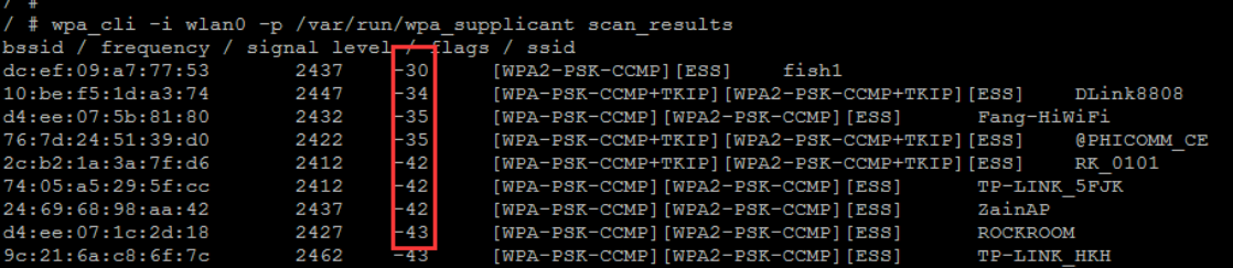
Note: Check if the number of scanned hotspots matches the approximate number of routers around you, and compare it with the Wi-Fi scan on your mobile device (if the customer’s module does not support 5G Wi-Fi, only compare the number of 2.4G Wi-Fi). Additionally, verify the signal strength of the router closest to the tester. If the router is very close to the tester but the signal strength is very weak (typically, good: -20 to -50, slightly weak but acceptable: -50 to -70, poor: -70 to -90), it is necessary to check whether the Wi-Fi module is connected to an antenna, and whether the module’s RF specifications are compliant, etc. Refer to Wi-Fi/BT Hardware RF Specifications.
4.1.3 Connect to Router
Modify Configuration File
# Add network configuration item in wpa_supplicant.conf
network={
    ssid="WiFi-AP"        # Wi-Fi Name
    psk="12345678"        # Wi-Fi Password
    key_mgmt=WPA-PSK      # Encryption configuration, change to key_mgmt=NONE for
no encryption
}

# Reload the above configuration for the wpa_supplicant process with the
following command:
wpa_cli -i wlan0 -p /var/run/wpa_supplicant reconfigure

# Initiate connection:
wpa_cli -i wlan0 -p /var/run/wpa_supplicant reconnect

# Connection Information
wpa_cli -i wlan0 -p /var/run/wpa_supplicant status
bssid=04:42:1a:b4:e7:7c
freq=5805
ssid=wwc3
id=0
mode=station
wifi_generation=6
pairwise_cipher=CCMP
group_cipher=CCMP
key_mgmt=SAE
pmf=2
mgmt_group_cipher=BIP
sae_group=19
sae_h2e=0
sae_pk=0
wpa_state=COMPLETED
ip_address=192.168.50.169
address=d4:9c:dd:f5:52:c4
uuid=47ed7266-da34-5c0b-884a-4fcc17648d87
ieee80211ac=1
4.2 Wi-Fi AP Hotspot Verification
The SDK integrates the relevant programs, and by executing softapDemo apName (to start a hotspot named apName with default no encryption), the hotspot mode can be activated. The location of the code and the compiled files are:
/external/softapDemo/src/main.c
buildroot/package/rockchip/softap/Config.in softap.mk
make softap-dirclean
make softap
If the softapDemo source code is not found, it can be downloaded from the following address to the external directory:
https://github.com/rockchip-linux/softapServer
Realtek Module: Use p2p0 for the softap function, and generate p2p0 through the kernel driver configuration. If there is no p2p0 node, please check the configuration here:
+++ b/drivers/net/wireless/rockchip_wlan/rtl8xxx/Makefile
@@ -1593,7 +1593,7 @@ endif
ifeq ($(CONFIG_PLATFORM_ARM_RK3188), y)
EXTRA_CFLAGS += -DCONFIG_PLATFORM_ANDROID
+EXTRA_CFLAGS += -DCONFIG_CONCURRENT_MODE
AMPAK/Azurewave Module: Use wlan1 as the softap function, and use the iw command to generate the wlan1 node. iw phy0 interface add wlan1 type managed Debugging and Customization Modification:
// Here you can add encryption, modify IP addresses, and DNS, etc., which can be
modified by yourself
int wlan_accesspoint_start(const char* ssid, const char* password)
{
    // Create softap hotspot configuration
    create_hostapd_file(ssid, password);
    // softap_name: wlan1/p2p0
    sprintf(cmdline, "ifconfig %s up", softap_name);
    // Set custom IP address
    sprintf(cmdline, "ifconfig %s 192.168.88.1 netmask 255.255.255.0",
softap_name);

    // Create a configuration file for the DHCP address pool
    creat_dnsmasq_file();
    int dnsmasq_pid = get_dnsmasq_pid();
    if (dnsmasq_pid != 0) {
        memset(cmdline, 0, sizeof(cmdline));
        sprintf(cmdline, "kill %d", dnsmasq_pid);
        console_run(cmdline);
    }
    memset(cmdline, 0, sizeof(cmdline));
    // Use dnsmasq as a DHCP server to assign IP addresses to devices
    sprintf(cmdline, "dnsmasq -C %s --interface=%s", DNSMASQ_CONF_DIR,
softap_name);
    console_run(cmdline);

    memset(cmdline, 0, sizeof(cmdline));
    // Start softap hotspot mode
    sprintf(cmdline, "hostapd %s &", HOSTAPD_CONF_DIR);
    console_run(cmdline);
    return 1;
}

// Create a DHCP configuration file, which must be consistent with your custom IP
address, otherwise, it will cause the mobile phone to be unable to obtain an IP
bool creat_dnsmasq_file()
{
    FILE* fp;
    fp = fopen(DNSMASQ_CONF_DIR, "wt+");
    if (fp != 0) {
        fputs("user=root\n", fp);
        fputs("listen-address=", fp);
        fputs(SOFTAP_INTERFACE_STATIC_IP, fp);
        fputs("\n", fp);
        fputs("dhcp-range=192.168.88.50,192.168.88.150\n", fp);
        fputs("server=/google/8.8.8.8\n", fp);
        fclose(fp);
        return true;
    }
    DEBUG_ERR("---open dnsmasq configuration file failed!!---");
    return false;
}

// Create an AP hotspot configuration file, which can be consulted with the Wi-Fi
manufacturer, and the parameters here are greatly related to the chip
specifications
int create_hostapd_file(const char* name, const char* password)
{
    FILE* fp;
    char cmdline[256] = {0};
    fp = fopen(HOSTAPD_CONF_DIR, "wt+");

    if (fp != 0) {
        sprintf(cmdline, "interface=%s\n", softap_name);
        fputs(cmdline, fp);
        fputs("ctrl_interface=/var/run/hostapd\n", fp);
        fputs("driver=nl80211\n", fp);
        fputs("ssid=", fp);
        fputs(name, fp);
        fputs("\n", fp);
        fputs("channel=6\n", fp);  // Channel setting
        fputs("hw_mode=g\n", fp);  // 2.4/5G configuration
        fputs("ieee80211n=1\n", fp);
        fputs("ignore_broadcast_ssid=0\n", fp);
#if 0  // If encryption is chosen, modify here
        fputs("auth_algs=1\n", fp);
        fputs("wpa=3\n", fp);
        fputs("wpa_passphrase=", fp);
        fputs(password, fp);
        fputs("\n", fp);
        fputs("wpa_key_mgmt=WPA-PSK\n", fp);
        fputs("wpa_pairwise=TKIP\n", fp);
        fputs("rsn_pairwise=CCMP", fp);
#endif
        fclose(fp);
        return 0;
    }
    return -1;
}

int main(int argc, char **argv)
    // According to the Wi-Fi model, set the corresponding hotspot interface. The
4.4 kernel can automatically obtain the Wi-Fi model through the
"/sys/class/rkwifi/chip" node,
    // but the kernel version 4.19 and later does not have this node, and the Wi-
Fi model can be determined in the following way
    // AMPAK/Azurewave: Check for the directory sys/bus/sdio/drivers/bcmsdh_sdmmc
    // Realtek: Check for the directory sys/bus/sdio/drivers/rtl8723ds
    if (!strncmp(wifi_type, "RTL", 3))
        strcpy(softap_name, "p2p0"); // Realtek uses p2p0
    else
        strcpy(softap_name, "wlan1"); // AMPAK/Azurewave uses wlan1

    ... ...
    if (!strncmp(wifi_type, "RTL", 3)) {
        // Realtek module automatically generates the p2p0 node after enabling
coexistence mode
        console_run("ifconfig p2p0 down");
        console_run("rm -rf /userdata/bin/p2p0");
        wlan_accesspoint_start(apName, NULL);
    } else {
        console_run("ifconfig wlan1 down");
        console_run("rm -rf /userdata/bin/wlan1");
        console_run("iw dev wlan1 del");
        console_run("ifconfig wlan0 up");
        // AP module needs the iw command to generate the wlan1 node for softap
use
        console_run("iw phy0 interface add wlan1 type managed");
        wlan_accesspoint_start(apName, NULL);
    }
After executing the command, you can see the corresponding AP on the Wi-Fi setting interface of the mobile phone. If not, please troubleshoot: First, ensure that the above-mentioned configuration files are set correctly; Confirm whether the ifconfig has seen the wlan1 or p2p0 node; Check if the hostapd/dnsmasq processes have started successfully;
4.3 BT Verification Test
First, ensure that the dts/Buildroot is configured correctly, refer to sections 2/3/7.2. This section provides instructions for two commonly used types of BT modules. With the correct configuration, the system will generate a script named bt_pcba_test (or in the latest SDK, a script named bt_init.sh). REALTEK Module
# UART Interface:
/ # cat usr/bin/bt_pcba_test (bt_init.sh)
#!/bin/sh

killall rtk_hciattach

echo 0 > /sys/class/rfkill/rfkill0/state   # Power down
echo 0 > /proc/bluetooth/sleep/btwrite
sleep 1
echo 1 > /sys/class/rfkill/rfkill0/state   # Power up
echo 1 > /proc/bluetooth/sleep/btwrite
sleep 1
insmod /usr/lib/modules/hci_uart.ko           # REALTEK module requires loading
the UART driver
rtk_hciattach -n -s 115200 /dev/ttyS4 rtk_h5 &   # The blue reference indicates
which UART port the Bluetooth is using

# Note: Kill the rtk_hciattach process before starting the test each time.

# Note: For USB interface Bluetooth, there is no sh script. Execute the following
manually:
echo 0 > /sys/class/rfkill/rfkill0/state   # Power down
echo 0 > /proc/bluetooth/sleep/btwrite
sleep 1
echo 1 > /sys/class/rfkill/rfkill0/state   # Power up
echo 1 > /proc/bluetooth/sleep/btwrite
sleep 1
insmod /usr/lib/modules/rtk_btusb.ko          # REALTEK module requires loading
the USB driver
AMPAK/Azurewave Module
/ # cat usr/bin/bt_pcba_test (bt_init.sh)
#!/bin/sh

killall brcm_patchram_plus1

echo 0 > /sys/class/rfkill/rfkill0/state  # Power down
echo 0 > /proc/bluetooth/sleep/btwrite
sleep 2
echo 1 > /sys/class/rfkill/rfkill0/state  # Power up
echo 1 > /proc/bluetooth/sleep/btwrite
sleep 2

brcm_patchram_plus1 --bd_addr_rand --enable_hci --no2bytes --
use_baudrate_for_download --tosleep 200000 --baudrate 1500000 --patchram
/system/etc/firmware/bcm43438a1.hcd /dev/ttyS4 &

# Note: Kill the brcm_patchram_plus1 process before starting the test each time.
Bcm44338a1.hcd represents the firmware file for the corresponding model of BT, /dev/ttyS4 indicates which UART port the Bluetooth is using. Note: Files such as rtk_hciattach , hci_uart.ko , bcm43438a1.hcd are only generated when the correct Wi-Fi/BT module is selected in the Buildroot configuration as described in section 2. If these files are missing, please check the configuration (refer to section 3). After executing the script, run as follows: Note: If the hciconfig command is not available, select BR2_PACKAGE_BLUEZ5_UTILS in the Buildroot configuration, compile, and update for testing hciconfig hci0 up hciconfig –a Normally, the following should be available:
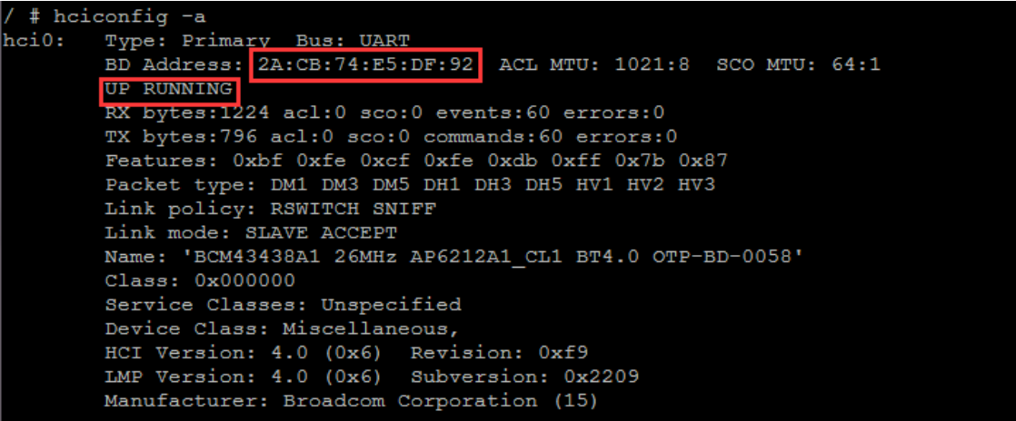
BT Scan: hcitool scan
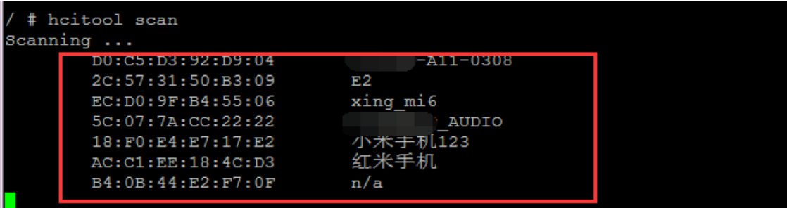
For abnormal situations, please refer to section 7.2 for troubleshooting.
4.4 Wi-Fi Wake on LAN (WoL)
Currently, Wi Fi supports network wake-up function, which means that once a device is connected to an Access Point (AP) and has obtained an IP address, it can be awakened by a wireless network packet (ping) after the device has been sleep. The general rule is that any network packet sent to the device can wake up the system. Modify the wpa_supplicant.conf file and add the following configuration:
wpa_supplicant.conf
ctrl_interface=/var/run/wpa_supplicant
update_config=1
ap_scan=1
+wowlan_triggers=any # Add this configuration
For Realtek Wi-Fi, please check the following configurations of the corresponding Makefile in the driver:
kernel/drivers/net/wireless/rockchip_wlan/rtl8xxx/Makefile
+CONFIG_WOWLAN = y
+CONFIG_GPIO_WAKEUP = y
DTS Configuration: Ensure that the schematics show that the WIFI_WAKE_HOST (or WL_HOST_WAKE) PIN is connected to the SoC, and then verify that the following DTS configuration is correct:
WIFI,host_wake_irq = <&gpio0 RK_PA0 GPIO_ACTIVE_HIGH>;
Test the system and Wi-Fi sleep:
dhd_priv setsuspendmode 1  # Only for AMPAK Azurewave modules, Realtek does not
require this command
echo mem > /sys/power/state
At this point, devices within the same local area network can ping this device, and normally, you will find the system has been awakened. Note that after the system wakes up, it is necessary to restore Wi-Fi in the normal working state:
dhd_priv setsuspendmode 0 # Only for AMPAK Azurewave modules, Realtek does not
require this command
Troubleshooting: If the system does not wake up as expected, please check whether the wake pin is configured correctly and whether the voltage level is correct, and whether the 32.768k has been turned off, etc.
4.5 Wi-Fi MONITOR Mode
AMPAK/Azurewave Wi-Fi
# Set the monitor channel:
dhd_priv channel 6  // channel numbers

# Enable monitor mode:
dhd_priv monitor 1

# Disable monitor mode:
dhd_priv monitor 0
Realtek Wi-Fi
# The driver Makefile needs to enable:
+ CONFIG_WIFI_MONITOR = y

# Bring up wlan0 and bring down p2p0
ifconfig wlan0 up
ifconfig p2p0 down

# Enable monitor mode
iwconfig wlan0 mode monitor
or
iw dev wlan0 set type monitor

# Switch to a specific channel
echo "<chan> 0 0" > /proc/net/<rtk_module>/wlan0/monitor // <rtk_module> is the
Realtek Wi-Fi module name, such as rtl8812au, rtl8188eu, etc.
4.6 Wi-Fi P2P Verification
# Create a new configuration file: p2p_supplicant.conf
ctrl_interface=/var/run/wpa_supplicant
update_config=1
device_name=p2p_device_name
device_type=10-0050F204-5
config_methods=display push_button keypad virtual_push_button physical_display
p2p_add_cli_chan=1
pmf=1
# Start: (kill the previous one first)
wpa_supplicant -B -i wlan0 -c /tmp/p2p_supplicant.conf
wpa_cli
> p2p_find
>

# At this point, open the P2P on the mobile device and you can search for the
device name specified above as device_name=p2p_device_name and click to connect

# At this point, the device side will display // Below is the test mobile device
> <3>P2P-PROV-DISC-PBC-REQ 26:31:54:8e:14:e7 p2p_dev_addr=26:31:54:8e:14:e7
pri_dev_type=10-0050F204-5 name='www' config_methods=0x188 dev_capab=0x25
group_capab=0x0

# The device side responds and sends a connection command, make sure the MAC
address matches the one above
>p2p_connect 26:31:54:8e:14:e7 pbc go_intent=1

> p2p_connect 26:31:54:8e:14:e7 pbc go_intent=1
OK
<3>P2P-FIND-STOPPED
<3>P2P-GO-NEG-SUCCESS role=client freq=5200 ht40=0 peer_dev=26:31:54:8e:14:e7
peer_iface=26:31:54:8e:94:e7 wps_method=PBC
<3>P2P-GROUP-FORMATION-SUCCESS
<3>P2P-GROUP-STARTED p2p-wlan0-2 client ssid="DIRECT-24-www" freq=5200
psk=3d67671b71f7a171118c1ace34ae5e4bcc8e17394394e258be91f55b7ab63748
go_dev_addr=26:31:54:8e:14:e7 [PERSISTENT]
> # At this point, the connection is successful
> quit

ifconfig
p2p-wlan0-2 Link encap:Ethernet  HWaddr 82:C5:F2:2E:7F:89
          inet addr:192.168.49.220  Bcast:192.168.49.255  Mask:255.255.255.0
          UP BROADCAST RUNNING MULTICAST  MTU:1500   Metric:1
          RX packets:470 errors:0 dropped:0 overruns:0 frame:0
          TX packets:344 errors:0 dropped:0 overruns:0 carrier:0
          collisions:0 txqueuelen:1000
          RX bytes:71779 (70.0 KiB)  TX bytes:33829 (33.0 KiB)
# It can be seen that the device is connected to the mobile phone, and if they
can ping each other, it indicates that it is normal.
4.7 Network Card Bridging Function
Scenario: Wi-Fi initiates wlan0 to connect to an accessible AP, and in conjunction with Section 4.2, it starts wlan1 or p2p0 as a hotspot, allowing a smartphone to connect to the hotspot and access the internet. The configuration is as follows, and the kernel has the following settings enabled:
+CONFIG_NETFILTER=y
+CONFIG_NF_CONNTRACK=y
+CONFIG_NF_TABLES=y
+CONFIG_NF_TABLES_INET=y
+CONFIG_NF_CONNTRACK_IPV4=y
+CONFIG_IP_NF_IPTABLES=y
+CONFIG_IP_NF_NAT=y
+CONFIG_IP_NF_TARGET_MASQUERADE=y
+CONFIG_BRIDGE=y
Execute the following two commands, with the IP address being the one configured when starting the softap:
iptables -t nat -A POSTROUTING -s 192.168.43.0/24 -o wlan0 -j MASQUERADE
echo "1" > /proc/sys/net/ipv4/ip_forward
4.8 Wi-Fi/BT Hardware RF Specifications
4.8.1 Testing Items
4.8.2 Wi-Fi/BT Section
Such as: Transmit Power, EVM, Crystal Frequency Deviation, Receiver Sensitivity, etc. Example: (b/g/n/ac)
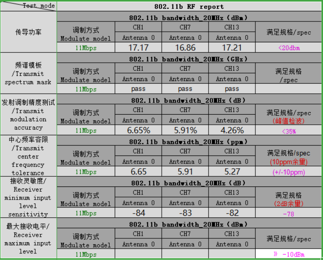
802.11b / 20 MHz / 11 Mbps / Antenna 0
| Metric | Unit | CH1 | CH7 | CH13 | Specification |
|---|---|---|---|---|---|
| Conducted power | dBm | 17.17 | 16.86 | 17.21 | <20 dBm |
| Transmit spectrum mask | GHz | pass | pass | pass | |
| Transmit modulation accuracy | dB / % | 6.65% | 5.91% | 4.26% | <35%; peak detection |
| Transmit center frequency tolerance | ppm | 6.65 | 5.91 | 5.27 | ±10 ppm; 10 ppm margin |
| Receiver minimum input level sensitivity | dB | -84 | -83 | -82 | -78; 2 dB margin |
| Receiver maximum input level | dBm | » -10 dBm |
4.8.3 Antenna Section
Passive S11 and active OTA testing of Wi-Fi Antennas in Devices Example:

Wi-Fi 2G TRP
| Mode | Channel | Frequency (MHz) | Tx average (dBm) | Sensitivity average (dBm) |
|---|---|---|---|---|
| 80211b: 11MBps | 1 | 2412 | 11.12 | -80.8 |
| 80211b: 11MBps | 7 | 2442 | 14.39 | -80.62 |
| 80211b: 11MBps | 13 | 2472 | 13.79 | -80.54 |
| 80211g: 54MBps | 1 | 2412 | 12.4 | -67.25 |
| 80211g: 54MBps | 7 | 2442 | 15.07 | -66.49 |
| 80211g: 54MBps | 13 | 2472 | 14.45 | -65.66 |
And organize the above tests into a formal report.
4.8.4 Testing Tools and Methods
The PDF/TXT documents mentioned below can be found in the docs/linux/wifibt directory. If the customer does not have professional testing equipment or has questions about testing, please contact the module manufacturer for assistance. For other platforms such as icomm-semi/altobeam/AIC, please seek the corresponding module manufacturer or original equipment manufacturer for testing tools and methods.
4.8.4.1 Realtek Testing
Generally, it divided into two types: COB and modules. Modules are usually strictly tested by the module manufacturer and come with pre-burned calibration data to the internal efuse by default. Customers only need to test and verify whether the performance indicators are qualified. However, COB requires the design of Wi-Fi peripheral circuits and the addition of components, so it is necessary to cooperate with Realtek for a complete RF calibration test, and integrate the calibrated data into the chip’s efuse or load it through the driver. For details, please consult the module manufacturer directly. Wi-Fi Testing
Refer to the Quick_Start_Guide_V6.txt, pay special attention to the command
iwpriv which should be uniformly replaced with rtwpriv.
BT Testing Refer to the “MP tool user guide for linux20180319.pdf ” (please consult the module manufacturer or the vendors for specific test content). It is particularly important to note that the test requires a dedicated Bluetooth firmware file provided by the module manufacturer for testing, and it must be placed in the specified directory to test the Bluetooth indicators.
# Note: Before performing the test, please turn on the BT power
echo 0 > sys/class/rfkill/rfkill0/state
echo 0 > /proc/bluetooth/sleep/btwrite
sleep 1
echo 1 > sys/class/rfkill/rfkill0/state
echo 1 > /proc/bluetooth/sleep/btwrite
# Special attention: The rtk_hciattach process should not run, if it does, please
terminate it with killall rtk_hciattach

///////////
/ #
/ # rtlbtmp
:::::::::::::::::::::::::::::::::::::::::::::::::
:::::::: Bluetooth MP Test Tool Starting ::::::::

>
>
>enable uart:/dev/ttyS4   # Note: ttySX corresponds to the actual hardware
connected uart port
>
>> > enable[Success:0]
4.8.4.2 Synopsys/Infineon Chip Testing
Wi-Fi Testing Firstly, it is necessary to replace with the test firmware: Each AP module corresponds to a different test firmware, for example:
AP6236 -> fw_bcm43436b0_mfg.bin
AP6212A -> fw_bcm43438a1_mfg.bin
The fw_bcmxxx_mfg.bin and APxxxx must match your module model, otherwise, it cannot be tested! Therefore, first confirm whether there is a test firmware of the corresponding model, and if not, obtain it from the module manufacturer. The latest SDK has built-in test firmware for supported models, so use the built-in test script directly to put Wi-Fi into RF test mode:
external\rkwifibt\wifi_ap6xxx_rftest.sh
#!/bin/sh
killall ipc-daemon netserver connmand wpa_supplicant

# Reset
echo 0 > /sys/class/rfkill/rfkill0/state
sleep 1
echo 1 > /sys/class/rfkill/rfkill1/state
sleep 1

# Set to update the test firmware
echo /vendor/etc/firmware/fw_bcmdhd_mfg.bin >
/sys/module/bcmdhd/parameters/firmware_path
sleep 1

# Restart wlan0
ifconfig wlan0 down
ifconfig wlan0 up
sleep 1
# Confirm whether it has entered the test mode
echo "wl ver"
wl ver
The outdated SDKs do not have built-in test firmware, and please refer to the following example:
# AP6236
# Push fw_bcm43436b0_mfg.bin to the data or other writable partition, then
execute the following commands: (Note the path below)
mount --bind /data/fw_bcm43436b0_mfg.bin /system/etc/firmware/fw_bcm43436b0.bin
ifconfig wlan0 down
ifconfig wlan0 up
wl ver

# CYW43438
echo /data/cyw43438-7.46.58.25-mfgtest.bin >
/sys/module/cywdhd/parameters/firmware_path
ifconfig wlan0 down
ifconfig wlan0 up
wl ver
If done correctly, executing wl ver will print a string containing the “WL_TEST” characters, indicating that it has entered the test mode. For detailed testing, please refer to:
Wi-Fi RF Test Commands for Linux-v03.pdf
Bluetooth Testing After executing the bt_init.sh script (SDK built-in script, refer to section 3.3), execute the following: (Note: If the hciconfig command is not available, please select BR2_PACKAGE_BLUEZ5_UTILS in Buildroot configuration to compile and update the test)
hciconfig hci0 up
hciconfig -a
If a hci0 node appears, it indicates that the initialization is complete. If it does not appear, there are two possibilities:
- The Bluetooth DTS configuration is abnormal, or there is a hardware anomaly, or the UART port configuration is incorrect, causing the initialization to fail;
- The Bluetooth firmware file configuration is incorrect or the file is missing; For the above two issues, please refer to sections 2/3 for BT-related troubleshooting; For specific test instructions, please refer to:
BT RF Test Commands for Linux-v05.pdf #The test steps 1/2 are already executed in
the script, no need to execute them again
4.9 Wi-Fi Performance Testing
Using iperf to test performance, please note: Two Points Affecting Performance It is essential to complete Wi-Fi RF testing and antenna OTA testing to ensure that the metrics are normal before testing performance; otherwise, it is meaningless. If significant data fluctuations are observed, please confirm in a location with minimal interference, such as an open space or basement (it is best to test in a shielded room). Testing Environment Due to the high level of interference in open environments, it is recommended to test in a shielded room environment, first ensuring that Wi-Fi can connect normally to the AP and obtain an IP address. Test Points The size of the throughput, as well as its stability and any fluctuations. Router Channels Tests should be conducted on low, medium, and high channels, such as channels 1/6/11: Test Commands Please refer to the document linked below for detailed instructions iPerf - iPerf3 and iPerf2 user documentation iperf2 / iperf3 (es.net) Note: The iperf command for the board needs to be configured in Buildroot: BR2_PACKAGE_IPERF = y BR2_PACKAGE_IPERF3 = y
5. Wi-Fi/BT Troubleshooting
Important: Always check the logs first and troubleshoot any anomalies based on the log!!! Wi-Fi/BT issues can generally be categorized into three types: SDIO/USB/PCIE devices not recognized; SDIO card recognized, but firmware loading failed; Performance issues, such as inability to connect/few scans/probable disconnections, etc.;
5.1 Brief Description of Wi-Fi Identification Process
SDIO Interface: During booting, the kernel MMC framework will recognize the SDIO card, first by parsing the GPIO configured by reset gopios attribute of the sdio_pwrseq node in dts, the GPIO is the WL_REG_ON, and then pulling it high. It then sends initialization commands to the module via SDIO_CLK/CMD/DATA. Initially, SDIO_CLK will send commands to the Wi-Fi module at a low frequency of 400/300/200K to obtain basic information about the Wi-Fi SDIO, such as whether it is SDIO2.0 (The maximum CLK is 50M) or 3.0 (The maximum CLK is 208M), and whether it supports 4 wires or 1 wire, etc. Then, according to the supported specifications, the SDIO_CLK frequency is increased to the corresponding high frequency of 50M/150M, and the basic initialization is completed. You can see the following log:
# Note that the number 0 in mmc0 is not fixed, it could also be 0/1/2; ff4a0000:
represents the address of the controller, which is also different from platforms
# Parse the mmc-pwrseq node in the dts, to obtain WL_REG_ON
dwmmc_rockchip ff4a0000.dwmmc: allocated mmc-pwrseq
# Low-frequency initialization
mmc_host mmc0: Bus speed (slot 0) = 400000Hz (... actual 400000HZ div = 0)
# High-frequency operation mode
mmc_host mmc0: Bus speed (slot 0) = 50000000Hz (... actual 50000000HZ div = 0)
# SDIO 2.0
mmc0: new high speed SDIO card at address 0001
# SDIO 3.0
mmcx: new ultra high speed SDR104 SDIO card at address 0001
USB/PCIE Interface: The identification process for these two interfaces is more complex. Please refer to the USB/PCIE related documents in the doc directory. After the identification is completed: USB Interface: If recognized normally, executing lsusb will show the following information:
Bus 001 Device 002: ID 0bda:f179 Realtek Semiconductor Corp. RTL8188FTV
802.11b/g/n 1T1R 2.4G WLAN Adapter
Or dmesg | grep usb to see if the USB device has been recognized. PCIE Interface: If recognized normally, executing lspci will show the following information:
0002:21:00.0 Network controller: Broadcom Inc. and subsidiaries Device 449d (rev
02)
Note: The above identification processes are all done during the boot process, and only after the correct device is recognized will the Wi-Fi driver be correctly loaded!
5.2 Troubleshooting Wi-Fi Issues
Wi-Fi is an SDIO Interface: There are generally two cases: First, confirm by checking the kernel log for the following LOG. If no, it indicates that the SDIO card has not been recognized. For such issues, refer to Section 7.1.1.
mmc0: new high speed SDIO card at address 0001
# or
mmcx: new ultra high speed SDR104 SDIO card at address 0001
If the normal recognition of the SDIO is seen in the LOG, but wlan0 is not present or fails to come up.
5.2.1 Wi-Fi Abnormality: SDIO Not Recognized
Firstly, it is strongly recommended to carefully re-examine the DTS/KERNEL configuration in Chapter 2!!! Follow these steps to troubleshoot in sequence according to the kernel LOG:
5.2.1.1 Measure Voltage
Measure the voltage levels and CLK frequency of the corresponding PINs according to the labels to ensure they are correct (Note: SDIO 3.0 mode must be 1.8V).
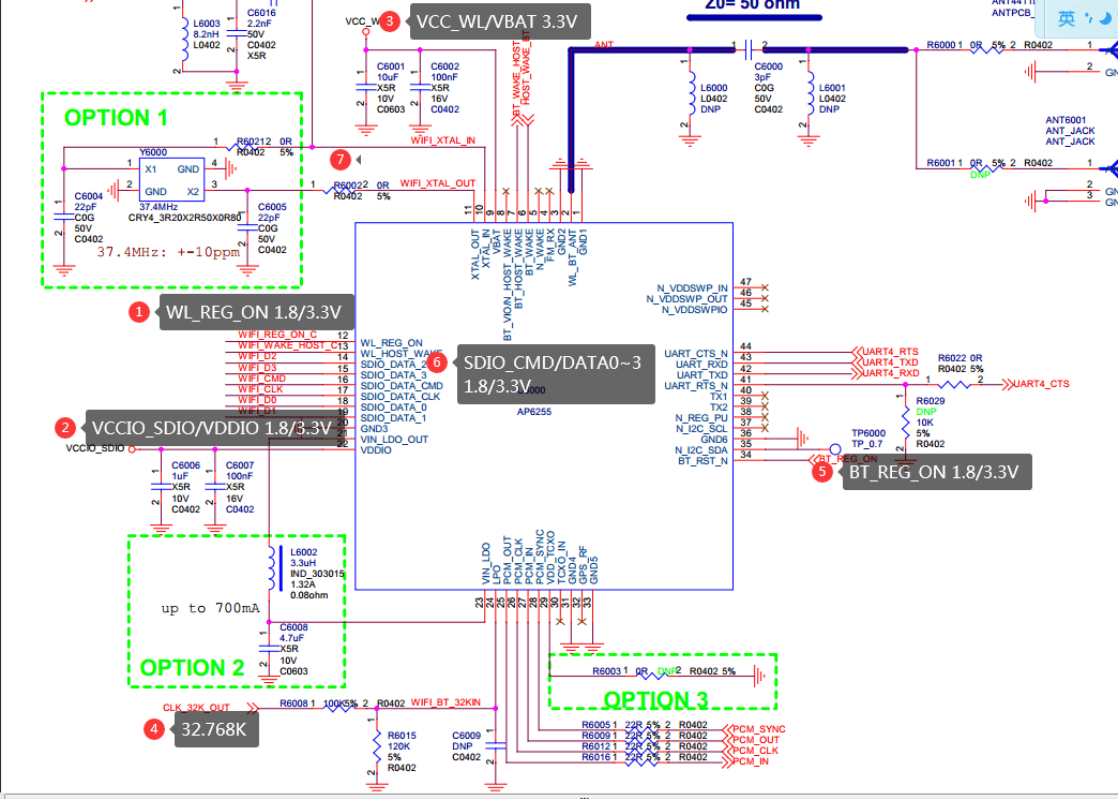
Use an oscilloscope to measure the timing of VBAT/VDDIO/WL_REG_ON and ensure it meets the following timing requirements:
5.2.1.2 Timing Sequence
Note: The following are the timing requirements for the AMPAK modules. It is important to check the requirements of the timing diagram in the datasheet of the module actually used,, and to pay special attention to the timing of VDDIO.
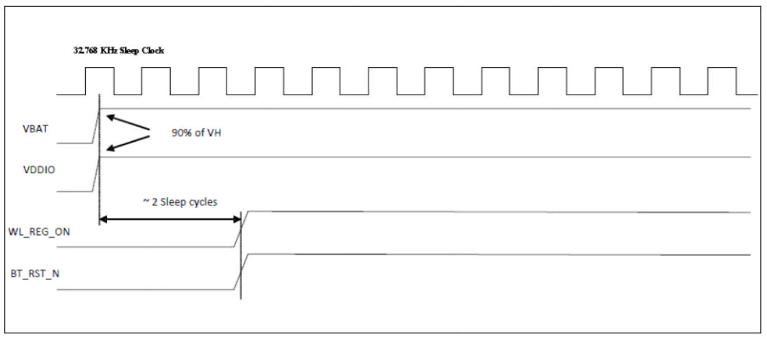
5.2.1.3 WL_REG_ON Configuration Error in the DTS
Causes the Wi-Fi enable pin not to be pulled high. It is possible to test its waveform with an oscilloscope to see if it is being pulled high or low, and to check if the voltage amplitude (1.8/3.3V) meets the requirements; if continuous high and low pulls are measured, it is a normal situation because the SDIO initialization will retry several times. Upon successful identification: WL_REG_ON will be pulled high, and if the identification fails, it will be pulled low; if it remains low, it indicates an incorrect DTS configuration. On the hardware side, directly pulling WL_REG_ON high for verification, if recognition is possible, it also suggests an incorrect DTS WL_REG_ON configuration.
mmcX: Bus speed (slot 0) = 300000Hz (slot req 300000Hz, actual 300000HZ div =
0)
mmcX: Bus speed (slot 0) = 200000Hz (slot req 200000Hz, actual 200000HZ div =
0)
mmcX: Bus speed (slot 0) = 100000Hz (slot req 100000Hz, actual 100000HZ div =
0)
5.2.1.4 WL_REG_ON Configuration Error in the DTS
5.2.1.5 VDDIO/SDIO/IO Power Domain
The VDDIO supplied to PIN12 should be 3.3/1.8V, and the corresponding SDIO_CMD/SDIO_DATA0~3 must also be 3.3V or 1.8V. VDDIO: The supply voltage does not match the DTS power domain configuration (refer to the IO power domain configuration).
5.2.1.6 SDIO_CLK Lacking Waveform
Incorrect settings in the I/O power domain may result in the absence of a waveform on the CLK; Check if a pull-up resistor has been added to the CLK pin, and test without it; The CLK waveform needs to be captured by setting the trigger mode;
5.2.1.7 Insufficient Power Supply or Excessive Voltage Fluctuation
VCC_WL/VBAT/VDDIO_SDIO: Insufficient Power Supply or Excessive Voltage Fluctuation
# Realtek Modules
RTL871X: ### rtw_hal_ops_check - Error : Please hook HalFunc.read_chip_version
###
RTL871X: ### rtw_hal_ops_check - Error : Please hook HalFunc.init_default_value
###
5.2.1.8 32.768K
External Clock Reference (Characteristics of External LPO Signal)
| Parameter | Specification | Units |
|---|---|---|
| Nominal Input Frequency | 32.768 | kHz |
| Frequency Accuracy | ± 30 | ppm |
| Duty Cycle | 30 - 70 | % |
| Input Signal Amplitude | 400 to 1800 | mV, p-p |
| Signal Type | Square-wave | - |
| Input Impedance | >100k <5 | Ω pF |
| Clock Jitter (Integrated over 300Hz – 15KHz) | <1 | Hz |
| Output High Voltage | 0.7Vio - Vio | V |
CLK_32K_OUT: 32.768K has no waveform, or the waveform accuracy does not meet the requirements of the above table!
# For AMPAK/Azurewave modules, the abnormal log for 32k:
[11.068180] dhdsdio_htclk: HT Avail timeout (1000000): clkctl 0x50
[11.074372] dhd_bus_init: clock state is wrong. state = 1
[12.078468] dhdsdio_htclk: HT Avail timeout (1000000): clkctl 0x50
[12.086051] dhd_net_bus_devreset: dhd_bus_devreset: -1
5.2.1.9 Inappropriate PCB Routing Quality/Capacitances/Inductances
SDIO_CLK/CMD/DATAX: Issues such as abnormal PCB routing, improper capacitances and inductances, poor contact, and poor soldering can lead to initialization exceptions or the inability to run at high frequencies. It is possible to lower the frequency for confirmation (modify the max- frequency under the &sdio node). If frequency reduction is possible, hardware engineers should measure the waveform to confirm compliance with the CLK/CMD/DATA Timing requirements in the datasheet of the Wi-Fi module. Method to modify the frequency:
&sdio {
+  max-frequency = <10000000>;   # Modify here to limit the frequency
5.2.1.10 io_domain Configuration
Please check if the Wi-Fi and the host controller SDIO voltages are mismatched, and verify that the software io_domain configuration matches the hardware (refer to section 2.2.3).
// Abnormal log 1
mmc_host mmc1: Bus speed(slot0)=100000000Hz(slotreq 100000000Hz,actual
100000000HZ div=0)
dwmmc_rockchip ff0d0000.dwmmc: All phases bad!
mmc1: tuning execution failed
mmc1: error -5 whilst initialising SDIO card

// Abnormal log 2, such as logs for data communication exceptions like firmware
download failure:
sdioh_buffer_tofrom_bus: TX FAILED ede95000, addr=0x08000, pkt_len=1968, ERR=-84
_dhdsdio_download_firmware: dongle image file download failed
dhd_bus_devreset Failed to download binary to the donglesdio

// Abnormal log 3
dwmmc_rockchip 30120000.rksdmmc: Busy; trying anyway
sdioh_buffer_tofrom_bus: RX FAILED c52ce000, addr=0x0f154, pkt_len=3752, ERR=-5
dhdsdio_membytes: membytes transfer failed
bcmsdh_sdmmc: Failed to Write byte F1:@0x1000a=00, Err: -5
dhdsdio_membytes: FAILED to set window back to 0x18100000
5.2.1.11 WL_HOST_WAKE
WLAN to wake-up RK HOST WL_HOST_WAKE PIN pin configuration error or intermittent power level or poor solder joint , causing the following anomalies or system hang-ups:
# AMPAK Azurewave module, exception log:
dhd_bus_rxctl: resumed on timeout, INT status=0x208000C0
dhd_bus_rxctl: rxcnt_timeout=1, rxlen=0
5.2.1.12 Poor Soldering on SDIO_D1~3 Pin
If logs similar to the following appear, and the issue persists even after reducing the max- frequency to below 10MHz:
[ 22.484301] mmc3: queuing unknown CIS tuple 0x80 (7 bytes)
[ 22.598965] xxx 148500000Hz (slot req 150000000Hz, actual 148500000HZ div = 0)
[ 23.466816] dwmmc_rockchip fe000000.dwmmc: Unexpected xfer timeout, state 3
[ 24.370310] dwmmc_rockchip fe000000.dwmmc: All phases bad!
[ 24.370391] mmc3: tuning execution failed: -5
Then modify it to test in 1-line mode:
&sdio {
+  bus-width = <1>;   /* Adjust to 1-line mode for testing */
If it is effective, it indicates that there is a hardware issue with one of the SDIOD1~3 pins, such as a poor solder joint or incorrect connection.
5.2.1.13 Defective Module/Chip
There is a small probability that the Master chip or Wi-Fi module may be defective. It is recommended to verify this by testing multiple units.
5.2.1.14 IOMUX Multiplexing Exception
pinctrl: pin gpio3-4 already requested by ff120000.serial; cannot claim for
ff5f0000.dwmmc
pinctrl: pin-100 (ff5f0000.dwmmc) status -22
pinctrl: could not request pin 100 (gpio3-4) from group sdmmc0ext-bus4 on device
dwmmc_rockchip ff5f0000.dwmmc: Error applying setting, reverse things
5.2.1.15 Additional Information
If the above troubleshooting steps do not resolve the issue, upload the following files to the Redmine system: dts/dtsi configuration, complete kernel log dmesg, and PDF schematic diagrams. Also, provide the power-on waveform diagrams for the three lines: WIFI_REG_ON, Wi- Fi_CLK, and Wi-Fi CMD.
5.2.2 USB Wi-Fi Troubleshooting
Normally, a USB Wi-Fi device will display information similar to the following; if not, the Wi-Fi driver will not load!
# USB device detected
usb 2-1: new high-speed USB device number 2 using ehci-platform
# Manufacturer's PID/VID
usb 2-1: New USB device found, idVendor=0bda, idProduct=b82c
usb 2-1: New USB device strings: Mfr=1, Product=2, SerialNumber=3
usb 2-1: Product: 802.11ac NIC
If the above information is not present, refer to section 2.2 for troubleshooting the module enable pin VBAT/WL_REG_ON to check if it is pulled high and whether the USB-related configurations are correct! Note: For RV1106/1103, sometimes it is necessary to manually enter the following command for recognition: echo 1 > /sys/devices/platform/ff3e0000.usb2-phy/otg_mode
5.2.3 Realtek Wi-Fi Precautions
5.2.3.1 WLAN0 Detected but Scanning Abnormal
FN-Link Wi-Fi Modules: PIN25 (corresponding to the 22nd PIN of the COB chip) is an internally multiplexed pin of the chip. One function is to serve as PCM_OUT, connecting to the PCM_IN of the Rockchip SoC for Bluetooth PCM call functionality; the other function is as the Wi-Fi IC LDO_SPS_SEL (SPS or LDO mode selection). When this pin is at a low level, it indicates SPS mode, and if it’s at a high level, it indicates LDO mode. Therefore, this PIN should either be at a high or low level; if a half-level is detected, it can cause the Wi-Fi to malfunction, such as being unable to scan SDIO or not detecting APs. If a half-level is measured, a pull-up treatment should be applied on the hardware. LB-LINK Modules: PIN7 must be connected with a pull-down resistor.
5.2.3.2 Realtek Support for SDIO 3.0
When using high-end modules such as RTL8821CS that support 3.0, there is a probability that initialization may fail, with the following abnormal log:
mmc_host mmc1: Bus speed (slot 0) = 400000Hz (slot req 400000Hz, actual 400000HZ
div = 0)
mmc_host mmc1: Voltage change didn't complete
mmc1: error -5 whilst initialising SDIO card
Please add the following patch:
diff --git a/drivers/mmc/core/sdio.c b/drivers/mmc/core/sdio.c
index 2046eff..6626752 100644
--- a/drivers/mmc/core/sdio.c
+++ b/drivers/mmc/core/sdio.c
@@ -646,7 +646,7 @@ static int mmc_sdio_init_card(struct mmc_host *host, u32 ocr,
* try to init uhs card. sdio_read_cccr will take over this task
* to make sure which speed mode should work.
*/
- if (!powered_resume && (rocr & ocr & R4_18V_PRESENT)) {
+ /*if (!powered_resume && (rocr & ocr & R4_18V_PRESENT)) {
  err = mmc_set_uhs_voltage(host, ocr_card);
  if (err == -EAGAIN) {
   mmc_sdio_resend_if_cond(host, card);
@@ -655,7 +655,10 @@ static int mmc_sdio_init_card(struct mmc_host *host, u32
ocr,
  } else if (err) {
   ocr &= ~R4_18V_PRESENT;
  }
- }
+ }*/
+
+ ocr &= R4_18V_PRESENT;
5.2.4 Wi-Fi SDIO Card Detected but wlan0 Up Failure
The following log in the kmesg log indicates that the SDIO card is recognized but the Wi-Fi is still not working.
mmcx: new high speed SDR104 SDIO card at address 0001
# or
mmcx: new ultra high speed SDR104 SDIO card at address 0001
The firmware file does not exist or the file name does not match the module model (only for AMPAK and Azurewave modules).
[dhd] dhd_conf_set_path_params : Final
clm_path=/vendor/etc/firmware/clm_bcm43438a1.blob
[dhd] dhd_conf_set_path_params : Final conf_path=/vendor/etc/firmware/config.txt
  dhdsdio_download_code_file: Open firmware file failed
/vendor/etc/firmware/fw_bcm43438a1.bin
_dhdsdio_download_firmware: dongle image file download failed
The power supply to the Wi-Fi module is unstable.
[ 14.059448] RTW: ERROR sd_write8: FAIL!(-110) addr=0x10080 val=0x00
[ 14.059602] RTW: ERROR _sd_cmd52_read: FAIL!(-110) addr=0x00086
[ 14.059615] RTW: ERROR sdio_chk_hci_resume((null)) err:-110
The Realtek module experiences scanning anomalies, such as not being able to detect an AP.
[ 43.860022] RTW: sdio_power_on_check: 0x1B8 test Pass.
[ 43.860115] RTW: _InitPowerOn_8723DS: Test Mode
[ 43.860156] RTW: _InitPowerOn_8723DS: SPS Mode
Both of buildin and KO Modes of Kernel Configuration are Selected or Mismatched Configuration
The Wi-Fi driver is loaded too early, causing an exception. The log shows that the driver is loaded within 1 second, at which point the sdio/usb device has not yet been enumerated. Check the kernel configuration section. The system loads two KOs simultaneously, one bcmdhd.ko and the other 88xx.ko, causing an exception. The reason is as described in section 3 of the compilation instructions.
5.2.5 SDIO Wi-Fi Anomaly After Running for a Period
SDIO_CLK/CMD/DATAX: Issues such as abnormal PCB routing, capacitors and inductors not meeting requirements, poor contact, or poor soldering can lead to initialization anomalies or the inability to run at high frequencies. It is possible to lower the frequency for confirmation (modify the max-frequency under the &sdio node). If frequency reduction is possible, it is necessary to check the hardware waveform to ensure it meets the CLK/CMD/DATA timing requirements in the datasheet of the Wi-Fi module. SDIO2.0: SDIO High Speed Mode Timing Diagram (CLK <= 50M); SDIO3.0: SDIO Bus Timing Specifications in SDR Modes (SDR104/DDR50) (50M < CLK <= 208M);
&sdio {
+  max-frequency = <10000000>;   # Modify this to limit the frequency
Case 2: Wi-Fi and the SDIO voltage of the SoC mismatch, please check if the software io_domian configuration is consistent with the hardware (refer to section 2.2.3).
5.2.6 Wi-Fi Connectivity Issues: AP Connection Failure, Instability, Slow Connection
Firstly, understanding the connection process, which includes the following steps:
- Scan and configure SSID; if the SSID is not found, the scanning process will repeat until the desired SSID is detected.
- Initiating connection and completing the 4 handshake.
- Obtaining an IP address via DHCP. These issues are generally caused by substandard RF or antenna specifications of the Wi-Fi chip or module. The verification method is as follows: Refer to section 4.1 for a simple software connection test! RF Specifications Firstly, provide a test report on the RF specifications of the board. If you don’t have one, please start with testing the basic specifications. Secondly, if the device is a complete unit including the case, please test whether the OTA (Over-The-Air) specifications for the antenna have been tested. If not, prioritize testing them. Ensure that the Wi-Fi RF specifications and the antenna’s OTA test reports for the complete unit are qualified, confirming that the hardware specifications are normal (Transmit Power, EVM, Crystal Frequency Deviation, Receive Sensitivity).
Scanning Comparison Perform a basic scanning comparison: place the test device and a smartphone at the same distance from the router and compare the number of scanned APs and their signal strength with a smartphone (or a similar specification competitor) to preliminarily determine if the hardware specifications are normal. The scanning method is referenced in Chapter 4.1. Here, we explain how to compare with a smartphone. Take an Android phone, go to Settings, then Developer Options, and enable the WLAN detailed logging option. Return to the WLAN settings interface to see the detailed information of APs, including RSSI. By comparing the number of hotspots and signal strength with the smartphone’s scan, you can preliminarily determine if the hardware specifications are qualified. Interference Eliminate interference factors, such as a large number of 2.4/5G wireless devices connecting simultaneously in the current environment, causing significant interference. In this case, place the test device and a comparison smartphone (or a similar specification competitor) at the same location. If both are abnormal, it can be judged as interference. If the smartphone operates normally, it can be determined that there is an anomaly in the hardware specifications. Distance Eliminate distance factors, as a signal too weak due to the distance (signal strength of the connected AP is between -70 to -90 as seen through wpa_cli scan/scan_r) can lead to communication failure. You can bring the devices closer to confirm. Router Compatibility Eliminate router compatibility issues by testing with routers from different manufacturers and models. Consistency Eliminate single board anomalies by comparing tests with two to three boards. Seek Assistance from Module Manufacturers You can directly seek assistance from module manufacturers or the Wi-Fi manufacturer. They have professional packet-sniffing instruments to capture packets in the air, which can quickly fix the issue. Bring the Environment to Our Shenzhen Office for Confirmation
5.2.7 Throughput Not Meeting Expectations
If it’s an SDIO interface, the RK platform interface only supports up to 150M, and the protocol supports up to 208M, so there will be some performance loss inherent in the hardware; Next, the RF indicators should be tested first, and if necessary, provide the test report and antenna OTA test report; Then, find a shielded room or a clean environment such as an underground parking lot for testing to rule out environmental interference and ensure that a clean environment is normal; Finally, CPU/DDR frequency fixing verification can be performed;
# DDR
cat /sys/devices/platform/dmc/devfreq/dmc/available_frequencies
echo userspace > /sys/devices/platform/dmc/devfreq/dmc/governor
echo 1560000000 > /sys/devices/platform/dmc/devfreq/dmc/min_freq
cat /sys/devices/platform/dmc/devfreq/dmc/cur_freq

# CPU
cat /sys/devices/system/cpu/cpu0/cpufreq/scaling_available_frequencies
cat /sys/devices/system/cpu/cpu0/cpufreq/scaling_available_governors
echo userspace > /sys/devices/system/cpu/cpu0/cpufreq/scaling_governor
echo 1992000 > /sys/devices/system/cpu/cpu0/cpufreq/scaling_min_freq
cat /sys/devices/system/cpu/cpu0/cpufreq/scaling_cur_freq

# Move the dw-mmc interrupt to another CPU core for verification

#References:
#For switching CPU core interrupt verification.
cat /proc/interrupts to view the corresponding interrupt number
echo 5 > /proc/irq/38/smp_affinity_list // Move the interrupt to CPU core 2 for
execution
cat /proc/interrupts // Check the count
5.2.8 IP Anomalies
Unable to obtain an IP address or experiencing IP address conflicts. Please confirm whether the dhcpcd or udhcpc process is active. dhcpcd: The default used by the SDK, it starts with the system and is a more complete DHCP client. udhcpcd: A streamlined DHCP client from busybox. Note: Do not enable both processes simultaneously, only use one of them!
5.2.9 Abnormal Wake-Up from Sleep Mode
After entering sleep mode, the device is frequently awakened by Wi-Fi. The following scenarios should be ruled out: The 32.768k clock of the Wi-Fi module is turned off after the device goes into sleep mode; The WIFI_REG_ON signal is pulled low; The WIFI_WAKE_HOST PIN has hardware instability, with level jitter (normally at a low level, and it triggers when it goes high); The AP/CY module does not execute the following specific commands to filter broadcast or multicast packets before and after Wi-Fi enters sleep mode:
# Execute before sleep:
dhd_priv setsuspendmode 1
# Execute after wake-up:
dhd_priv setsuspendmode 0
5.2.10 PING Unreachable or High Probability of Latency
RF/antenna metrics have not been measured; It is highly probable that Wi-Fi is performing a scanning operation, resulting in significant ping latency; The router or PC firewall may be enabled, leading to a block on ping operations;
5.2.11 Customer Custom Modifications
If you have made modifications to the driver code, please be sure to inform us. We often receive reports of unusual issues that, upon investigation, are found to be caused by customers modifying Wi-Fi/BT driver configurations.
5.2.12 wlan0 Normal, but Unable to Scan Any AP
Check if the crystal oscillator corresponding to the module matches the chip’s requirements, such as a Wi-Fi requirement of 24M but a 37M is connected; The accuracy of 32.768k does not meet the requirements;
5.2.13 Icomm-semi Wi-Fi Anomaly
On the RV1109/1126 platform, it was found that the SDIO could be recognized, but there were read/write errors. The following modification was attempted:
&sdio {
 //rockchip,default-sample-phase = <90>; # Remove this configuration option
}
5.2.14 iPhone Issues
Issue: After an iOS device connects to a hotspot, the network will disconnect and then automatically reconnect after approximately 10 seconds. Resolution: The device will generate a DHCP lease file for the iOS device, which will be stored in a temporary location and will be lost upon reboot. When using dnsmasq to assign IP addresses, the following parameter must be specified in the startup command: -l, –dhcp-leasefile=<path> # The path must be persistent and not lost when power is cut.
5.2.15 AMPAK/Infineon/Azurewave/Synopsys Module Issues
Common Issues: Incorrect WIFI_REG_ON configuration;
32.768K signal is not present or does not meet the required standards;
WIFI_WAKE_HOST: Incorrect pin configuration or power level configuration, leading to initialization failure or high CPU usage by the dhd_dpc thread; refer to DTS Configuration
/* Pin control configuration for WIFI_WAKE_HOST */
wireless-wlan {
    /omit-if-no-ref/
    wifi_wake_host: wifi-wake-host {
        /* Note that the Wi-Fi wake host pin is typically triggered by a high
level,
         * so it should be configured as pulled down here by default; if the
customer's
         * hardware design is inverse, it should be changed to pulled up, in any
case,
         * it should be initialized to a state opposite to the trigger level.
         */
        rockchip,pins = <0 RK_PA0 0 &pcfg_pull_down>;
    };
};
The 32.768K signal is turned off during sleep, or WIFI_REG_ON is turned off; Firmware/nvram does not exist, and errors in the file download process are clearly visible in the logs; AMPAK (bcmdhd.ko) / Azurewave (cywdhd.ko) module drivers are not interchangeable, do not configure the wrong driver.
5.2.16 PCIe Wi-Fi Not Recognized
Please refer to the PCIE Wi-Fi Configuration section, check all the mentioned configurations, and be sure to measure the relevant power supply voltages to ensure they are normal!
5.3 Bluetooth Issues
Bluetooth Test Items Failure or Abnormal BT Bluetooth Function of rkwifibt-app-test, There are several situations below, please carefully troubleshoot the following steps: The Realtek module must turn off this kernel configuration: CONFIG_BT_HCIUART=n Refer to the Bluetooth Kernel Configuration section; DTS BT (BT_RST_N) power enable PIN configuration is incorrect, refer to Bluetooth Configuration; You can confirm with the following commands:
echo 0 > sys/class/rfkill/rfkill0/state # Pull down BT_REG_ON, measure the
corresponding PIN with a multimeter
echo 0 > /proc/bluetooth/sleep/btwrite

echo 1 > sys/class/rfkill/rfkill0/state # Pull up BT_REG_ON, measure the
corresponding PIN with a multimeter
echo 1 > /proc/bluetooth/sleep/btwrite
UART configuration error, refer to sections 2.2.2/2.4.2/2.5; The Realtek module requires rtk_hciattach / hci_uart.ko / rtk_btusb.ko, confirm that it has not been correctly compiled or there is a kernel configuration error, refer to sections
2.5/3.3;
# Initialize Bluetooth, only for UART module use
/usr/bin/rtk_hciattach

# Check if the kernel's CONFIG_BT_HCIUART configuration has been removed, and
whether the corresponding ko file has been generated
/usr/lib/modules/hci_uart.ko

# Whether the USB interface has generated the corresponding USB driver
/usr/lib/modules/rtk_btusb.ko
Bluetooth Firmware/config file does not exist or does not match the Bluetooth module model, refer to section 3.3;
# AMPAK Azurewave module, for example: AP6212A: The corresponding file is
bcm43438a1.hcd
/system(vendor)/etc/firmware/BCMxxxx.hcd

# RTL SDIO interface RTL8723DS corresponding file
/lib/firmware/rtlbt/rtl8723d_fw
/lib/firmware/rtlbt/rtl8723d_config

# RTL USB interface RTL8821CU corresponding file
/lib/firmware/rtl8821cu_fw
/lib/firmware/rtl8821cu_config
Hardware wiring error of BT UART RTS/CTS, leading to abnormal initialization recognition
# AMPAK, Azurewave module, all 4 lines must be connected to the main control
host tx  - controller rx
host rx  - controller tx
host rts - controller cts
host cts - controller rts

# Realtek module
# For COB chips that directly use Realtek Bluetooth: The hardware wiring of
the UART interface is as follows:
host tx  - controller rx
host rx  - controller tx
host rts - controller cts
host cts - ground # The main control cts should be grounded

# For the RTL8822C chip, which is special, all 4 lines must be connected to
the main control
host tx  - controller rx
host rx  - controller tx
host rts - controller cts
host cts - controller rts
# For modules, the module factory generally internally grounds the controller
rts, so there is no need for the main control to ground it, just connect it
directly to the controller
# rts; Pay special attention: Realtek has a large number of agents, and each
module may be different, so it is necessary to confirm with the module
factory, if
# the controller rts is not grounded, then the main control needs to ground
it.
host tx  - controller rx
host rx  - controller tx
host rts - controller cts
host cts - controller rts
6. Wi-Fi/BT New Module Porting and Driver Update
Special Attention: Be sure to familiarize yourself and understand the file storage rules and compilation rules in Chapter 3; this is crucial for the porting process; For the driver update scenario, some of the following steps can be omitted based on actual circumstances;
6.1 Realtek Module
6.1.1 Wi-Fi Section
Take the RTL8821CS as an example: Firstly, obtain the corresponding porting package from the module manufacturer or the original factory, similar to the following: 20171225_RTL8821CS_WiFi_linux_v5.2.18_25830_BT_ANDROID_UART_COEX_8821CS- B1d1d_COEX20170908-1f1f Wi-Fi Driver Part, navigate to the following directory: WiFi\RTL8821CS_WiFi_linux_v5.2.18_25830_COEX20170908-1f1f.20171225\driver Add Corresponding Compilation Configuration Copy the driver files to drivers/net/wireless/rockchip_wlan/ , rename to rtl8821cs, and modify Makefile/Kconfig to add the corresponding configurations. This step is not necessary when updating the driver.
drivers/net/wireless/rockchip_wlan/Makefile
+ obj-$(CONFIG_RTL8821CS) += rtl8821cs/

drivers/net/wireless/rockchip_wlan/Kconfig
+ source "drivers/net/wireless/rockchip_wlan/rtl8821cs/Kconfig"
Modify Makefile
# Change to RK platform:
CONFIG_PLATFORM_I386_PC = n
CONFIG_PLATFORM_ARM_RK3188 = y

# RK platform needs to remove the following configuration:
ifeq ($(CONFIG_PLATFORM_ARM_RK3188), y)
-EXTRA_CFLAGS += -DRTW_ENABLE_WIFI_CONTROL_FUNC # Remove this configuration if it
exists
# Modify the ko name to be consistent with the BR2_PACKAGE_RKWIFIBT_WIFI_KO
configuration in the following Buildroot config.in!
MODULE_NAME := 8821cs

# If there is a need for Wi-Fi sleep to maintain connection (WOWLAN), enable the
following configurations:
CONFIG_WOWLAN = y
CONFIG_GPIO_WAKEUP = y
If there is a need for WOWLAN, then add the irq acquisition function for the WL_HOST_WAKE pin
# Modify platform\platform_ops.c
+#include <linux/rfkill-wlan.h>
+extern unsigned int oob_irq;
int platform_wifi_power_on(void)
{
    int ret = 0;

+    oob_irq = rockchip_wifi_get_oob_irq();   // This corresponds to the
WIFI_WAKE_HOST PIN in the dts

    return ret;
}
Custom MAC Address Requirement
# Modify: core\rtw_ieee80211.c
+include <linux/rfkill-wlan.h> // Add header file
# Find the rtw_macaddr_cfg function
void rtw_macaddr_cfg(u8 *out, const u8 *hw_mac_addr)
-/* Use the mac address stored in the Efuse */
-if (hw_mac_addr) {
-    rtw_memcpy(mac, hw_mac_addr, ETH_ALEN);
-    goto err_chk;
-}

+ /* Use the mac address stored in the Efuse */
+ if (hw_mac_addr) {
+     _rtw_memcpy(mac, hw_mac_addr, ETH_ALEN);
+ }

+ if (!rockchip_wifi_mac_addr(mac)) {
+     printk("get mac address from flash=[%02x:%02x:%02x:%02x:%02x:%02x]\n",
mac[0], mac[1],
+         mac[2], mac[3], mac[4], mac[5]);
+     }
+ }
Add Driver Loading Entry
/* SDIO Interface: os_dep\linux\sdio_intf.c */
/* USB Interface: os_dep\linux\usb_intf.c */
/* PCIE Interface: os_dep\linux\pci_intf.c */

// At the end of this file, add the following code:
#include "rtw_version.h"
#include <linux/rfkill-wlan.h>
extern int get_wifi_chip_type(void);
extern int rockchip_wifi_power(int on);
extern int rockchip_wifi_set_carddetect(int val);

int rockchip_wifi_init_module_rtkwifi(void)
{
    rockchip_wifi_power(1);
    rockchip_wifi_set_carddetect(1);
    return rtw_drv_entry();
}

void rockchip_wifi_exit_module_rtkwifi(void)
{
    rtw_drv_halt();
    rockchip_wifi_set_carddetect(0);
    rockchip_wifi_power(0);
}

// For KO mode
module_init(rockchip_wifi_init_module_rtkwifi);
module_exit(rockchip_wifi_exit_module_rtkwifi);

// Comment out the following, and make sure to remove the __init __exit entries
for the two functions below
//module_init(rtw_drv_entry);
//module_exit(rtw_drv_halt);
Possible Compilation Error Handling
rtl8xxx\os_dep\linux\rtw_android.c // Comment out the following two lines
#if (LINUX_VERSION_CODE >= KERNEL_VERSION(2, 6, 39)) ||
defined(COMPAT_KERNEL_RELEASE)
void *wifi_get_country_code(char *ccode)
{
    RTW_INFO("%s\n", __FUNCTION__);
    if (!ccode)
        return NULL;
-    if (wifi_control_data && wifi_control_data->get_country_code)
-        return wifi_control_data->get_country_code(ccode);
    return NULL;
}
#endif /* (LINUX_VERSION_CODE >= KERNEL_VERSION(2, 6, 39)) */
6.1.2 Bluetooth BT Section
UART Interface If the corresponding module supports Bluetooth, it is necessary to obtain a software package similar to the following from the original manufacturer:
20201130_ANDROID_BT_DRIVER_RTL8822C_COEX_v1c1c.tar.xx
Taking the RTL8821CS as an example (for updating drivers, simply replace the corresponding files):
# Place or update the Bluetooth firmware and configuration files in the following
directory:
ls external/rkwifibt/realtek/
# The structure is as follows:
external/rkwifibt/realtek/RTL8821CS # Create a new directory if it does not exist
├── rtl8821cs_config
└── rtl8821cs_fw

# Note: The name of the RTL8821CS directory must match the configuration in the
Buildroot rkwifibt Config.in:
# BR2_PACKAGE_RKWIFIBT_"RTL8821CS"
USB Interface If a USB interface Bluetooth is used, the original manufacturer will provide a similar porting package, taking RTL8821CU as an example:
# tree
Linux_BT_USB_v3.10_20190430_8821CU_BTCOEX_20190509-4139.tar.xx
or
20201130_ANDROID_BT_DRIVER_RTL8821CU_COEX_v1c1c.tar.xx
|-8821CU                  # Firmware file
|-bluetooth_usb_driver    # USB driver

# Copy or update to the external/rkwifibt/realtek/ directory, the result is as
follows:
# external/rkwifibt/realtek$ tree
├── RTL8821CU
│   ├── rtl8821cu_config   # Bluetooth config
│   └── rtl8821cu_fw    # Bluetooth firmware
├── bluetooth_usb_driver   # RTL8821CU Bluetooth USB driver, compiled into
rtk_btusb.ko
    ├── Makefile
    ├── rtk_bt.c
    ├── rtk_bt.h
    ├── rtk_coex.c
    ├── rtk_coex.h
    ├── rtk_misc.c
    └── rtk_misc.h
6.2 AMPAK Module
Take AP6256 as an example, request the Wi-Fi and BT firmware package for AP6256 from the module manufacturer (for updating the driver, simply replace the corresponding files).
external\rkwifibt\firmware\broadcom//Create a folder named AP6256 in this
directory and store the files as follows:
external/rkwifibt/firmware/broadcom/AP6256$ tree
├── bt
│   └── BCM4345C5.hcd
└── wifi
    ├── fw_bcm43456c5_ag.bin
    ├── fw_bcm43456c5_ag_mfg.bin
    └── nvram_ap6256.txt
//Note the name of the AP6256 directory should match the configuration in the
following wifi Config.in: BR2_PACKAGE_RKWIFIBT_AP6256
The kernel driver part does not need to be modified and is basically compatible with all AP modules. By default, use the CONFIG_AP6XXX configuration.
6.3 Third-Party Wi-Fi Driver Porting Guide
For Wi-Fi modules not supported by the SDK, the following instructions can be referred to for porting: Refer to Section 2.2 for DTS Configuration, which mainly configures: WIFI_REG_ON: The power pin of the Wi-Fi module; WIFI_WAKE_HOST: The pin for the Wi-Fi module to wake up the host controller (optional, generally used by Broadcom/Realtek modules); The above GPIO configurations will be parsed by the kernel’s net/rfkill/rfkill-wlan.c and provide the following interfaces to the Wi-Fi driver:
/* SDIO card detection function */
int rockchip_wifi_set_carddetect(int val)

/* Wi-Fi driver to obtain the GPIO pin for the wake-up interrupt of the host
controller, optional */
int rockchip_wifi_get_oob_irq(void)
/* The trigger level of the interrupt, used in conjunction with the above API */
int rockchip_wifi_get_oob_irq_flag(void)

/* Wi-Fi power on and off functions */
int rockchip_wifi_power(int on)
The Wi-Fi driver can call the above interfaces according to the actual situation; Driver Compilation: It is necessary to specify the kernel directory and the corresponding RK compiler:
# The variable names below should be modified according to the actual situation:
diff --git a/Makefile b/Makefile
index 649da3c..d0b128d 100644
--- a/Makefile
+++ b/Makefile

+KDIR=/home/rk/kernel/
+ARCH=arm or arm64
+CROSS_COMPILE=SDK/prebuilts/gcc/linux-x86/arm/gcc-linaro-6.3.1-2017.05-
x86_64_arm-linux-gnueabihf/bin/arm-linux-gnueabihf-
7. Common Features and Configuration
Instructions
7.1 Wi-Fi/BT Adapter Instructions for Debian and Other Third-Party Systems
Debian/Kylin/UOS Systems These systems have complete Wi-Fi/BT applications (NetworkManager/blumeman/gnome- bluetooth) at the upper layer. Our work is simply to initialize the interfaces before the system starts; for example, for Wi-Fi: ifconfig should show the wlan0 interface; for Bluetooth: hciconfig should show the hci0 interface. Note that the DTS/kernel configuration for Wi-Fi/BT is independent of the specific system and is a universal configuration, which should be directly referenced from Section 2 for basic DTS and kernel configuration. The following sections will explain the interface initialization: For Yocto and other Buildroot-like systems, it is necessary to enable the wpa_supplicant/bluez protocol stack to support Bluetooth functionality
# After compilation, binaries such as bluetoothd/bluetoothctl/hciconfig will be
generated
$ bluetoothd -ndC &    # Start bluetoothd
$ bluetoothctl    # Enter interactive mode
[bluetooth]# power on
[bluetooth]# scan on
[bluetooth]# help  # View more commands
Note: The application tools and compilation mentioned above should be referenced from the documentation and instructions of the corresponding system.
7.1.1 AMPAK Module Adaptation Example
### Example with AP6275P, obtain the three files from the AMPAK module
manufacturer
# Bluetooth Initialization File: brcm_patchram_plus1.c, compile it with the
system's compiler into an executable file brcm_patchram_plus1 and place it into
the system
external/rkwifibt/brcm_tools/brcm_patchram_plus1.c # If there is RKSDK, it can be
obtained from this directory

# BT firmware file: Store according to the actual system requirements, no special
requirements, the following brcm_patchram_plus1 Bluetooth initialization program
will require specifying the firmware path;
BCM4362A2.hcd

# Wi-Fi firmware file: Store according to the actual system requirements
clm_bcm43752a2_pcie_ag.blob
fw_bcm43752a2_pcie_ag.bin
fw_bcm43752a2_pcie_ag_apsta.bin
nvram_AP6275P.txt

### Configuration
# Check the kernel Wi-Fi configuration and enable the following configurations:
CONFIG_WL_ROCKCHIP=y
CONFIG_WIFI_BUILD_MODULE=y
CONFIG_BCMDHD=y
CONFIG_AP6XXX=m
CONFIG_BCMDHD_PCIE=y #PCIE interface, mutually exclusive with SDIO, do not
configure if not PCIE
CONFIG_BCMDHD_SDIO=y #SDIO interface, mutually exclusive with PCIE

### Wi-Fi Interface Initialization
# After compiling with make, a ko file will be generated, store this file
according to your actual needs and load the Wi-Fi by opening this ko;
drivers/net/wireless/rockchip_wlan/rkwifi/bcmdhd/bcmdhd.ko

# Enable Wi-Fi: Load the ko first, and specify the firmware/nvram path when
insmod, change xx_path to the actual path used:
insmod /ko_path/bcmdhd.ko firmware_path=/fw_path/ nvram_path=/nvram_path/
ifconfig -a    #Normally, you can see wlan0, if not, refer to Chapter 2 and
Chapter 7 for troubleshooting

### Bluetooth Interface Initialization
# To enable Bluetooth, reset the BT power first:
echo 0 > /sys/class/rfkill/rfkill0/state   #Turn off BT power, equivalent to
rfkill block operation
echo 0 > /proc/bluetooth/sleep/btwrite
sleep 0.2
echo 1 > /sys/class/rfkill/rfkill0/state   #Turn on BT power, equivalent to
rfkill unblock operation
echo 1 > /proc/bluetooth/sleep/btwrite
sleep 0.2
# Initialize Bluetooth command, --patchram specifies the path of the Bluetooth
firmware file (modify according to the actual situation), /dev/ttyS8 is the
corresponding hardware serial port (modify according to the actual situation)
brcm_patchram_plus1 --bd_addr_rand --enable_hci --no2bytes --
use_baudrate_for_download --tosleep 200000 --baudrate 1500000 --patchram
/system/etc/firmware/BCM4362A2.hcd /dev/ttyS8 &
# If the system has installed the bluez protocol stack, use the hciconfig
command, you can see the hci0 node
hciconfig -a

# Disable Bluetooth
echo 0 > /sys/class/rfkill/rfkill0/state   #Turn off BT power, equivalent to
rfkill block operation
echo 0 > /proc/bluetooth/sleep/btwrite

# Be sure to kill the brcm_patchram_plus1 process, because it will be executed
again when turned on, otherwise it will conflict;
killall brcm_patchram_plus1

# The above enable/disable operations should be ported to your system according
to the actual situation;

# Note: If the application layer turns on/off Bluetooth by calling rfkill block
to turn off Bluetooth power, then when unblocking to turn on Bluetooth power
again, you must execute the brcm_patchram_plus1 Bluetooth initialization command
again, otherwise Bluetooth cannot be used; if the upper layer is only hciconfig
hci0 down/up, there is no need to call the repeated initialization;
7.1.2 Realtek Module Adaptation Example
Wi-Fi Adaptation Instructions Take the RTL8822CS as an example, first obtain the driver package for the corresponding module from the module manufacturer.
# For Wi-Fi: RTL8822CS_WiFi_linux_v5.12.1.5-1-g0e1519e_COEX20210504-2323.20210527
# For BT: 20201202_LINUX_BT_DRIVER_RTL8822C_COEX_v1c1c

### Wi-Fi Adaptation
# Refer to Section 8.1 for porting the Wi-Fi driver to the RK platform, and refer
to Section 2 for basic dts and kernel configuration
# After compiling with make, a ko file will be generated. Place this file
according to your actual needs and load the Wi-Fi with this ko file;
drivers/net/wireless/rockchip_wlan/rkwifi/rtl8822cs/8822cs.ko

# Realtek does not require firmware/nvram files, the timing of insmod execution
should be adjusted according to the system requirements;
insmod /ko_path/88xxxx.ko
# Normally, you should see wlan0, if not, refer to Section 2 and Section 7 for
troubleshooting
ifconfig -a

### Bluetooth Adaptation
# fw/config file explanation:
# Only Bluetooth requires fw/config files (found in the driver package), and the
storage location is related to the interface
# For RTL UART interface, the corresponding file for RTL8822CS should be placed
in the following location
/lib/firmware/rtlbt/rtl8822cs_fw
/lib/firmware/rtlbt/rtl8822cs_config
# Copy the correct FW file and config file to the correct path. (Copy the
firmware/config file)
$ sudo mkdir -p /lib/firmware/rtlbt/
$ sudo cp rtkbt-firmware/lib/firmware/rtlbt/rtl8xxxx_fw /lib/firmware/rtlbt/
$ sudo cp rtkbt-firmware/lib/firmware/rtlbt/rtl8xxxx_config /lib/firmware/rtlbt/

# For RTL USB interface, the corresponding file for RTL8822CU (copy the
corresponding fw/config files to the system's corresponding location)
/lib/firmware/rtl8822cu_fw
/lib/firmware/rtl8822cu_config
# Copy the correct FW file and config file to the correct path.
$ sudo cp rtkbt-firmware/lib/firmware/rtl8xxxxx_fw /lib/firmware/
$ sudo cp rtkbt-firmware/lib/firmware/rtl8xxxxx_config /lib/firmware/

# rtk_hciattach/hci_uart/usb.ko file explanation

# hci_uart/usb.ko file explanation, Realtek does not use the built-in interface
driver of the kernel, the kernel must first remove the following two
configurations:
CONFIG_BT_HCIBTUSB
CONFIG_BT_HCIUART

### Initialization Instructions
# UART Interface:
killall rtk_hciattach # First, make sure to stop this process if it was
previously started (if applicable)
echo 0 > /sys/class/rfkill/rfkill0/state # Power off
echo 0 > /proc/bluetooth/sleep/btwrite
sleep 0.5
echo 1 > /sys/class/rfkill/rfkill0/state # Power on
echo 1 > /proc/bluetooth/sleep/btwrite
sleep 0.5
insmod /usr/lib/modules/hci_uart.ko    # Realtek module requires loading the uart
driver
rtk_hciattach -n -s 115200 /dev/ttyS4 rtk_h5 & # ttySX refers to which uart port
the Bluetooth is using

# If the system has the bluez protocol stack installed, use the hciconfig command
hciconfig -a # Normally, you should see the hci0 node, if not, refer to Section 2
and Section 7 for troubleshooting

# USB Interface:
echo 0 > /sys/class/rfkill/rfkill0/state # Power off
echo 0 > /proc/bluetooth/sleep/btwrite
sleep 0.5
echo 1 > /sys/class/rfkill/rfkill0/state # Power on
echo 1 > /proc/bluetooth/sleep/btwrite
sleep 0.5
insmod /usr/lib/modules/rtk_btusb.ko   # Realtek module requires loading the usb
driver
# If the system has the bluez protocol stack installed, use the hciconfig
command, and you should normally see hci0
hciconfig -a
Bluetooth Driver/rtk_hciattach Tool Compilation Instructions
### Realtek UART/USB Bluetooth Driver ko Driver Compilation:
$ make -C /home/rk/rk3xxx/kernel/
 CROSS_COMPILE=/home/rk/rk3xxx/prebuilts/gcc/linux-x86/aarch64/gcc-arm-10.3-
2021.07-x86_64-aarch64-none-linux-gnu/bin/aarch64-none-linux-gnu- ARCH=arm64
M=/home/rk/rk3xxx/usb(uart)/bluetooth_usb(uart)_driver/
# -C specifies the kernel directory
# CROSS_COMPILE specifies the path to the cross-compiler toolchain
# ARCH specifies the system platform
# M specifies the path to the uart/usb driver
# Note that the paths must be absolute
# After a successful compilation,

# rtk_hciattach UART Initialization Program Compilation:
$ make CROSS_COMPILE=/home/rk/rk3xxx/prebuilts/gcc/linux-x86/aarch64/gcc-arm-
10.3-2021.07-x86_64-aarch64-none-linux-gnu/bin/aarch64-none-linux-gnu- -C
/home/rk/rk3xxx/uart/rtk_hciattach/
# -C specifies the kernel directory
# CROSS_COMPILE specifies the path to the cross-compiler toolchain
7.1.3 Automated Integration of Related Files
The adaptation instructions mentioned above are completed through manual compilation or push operations. After debugging is complete, to simplify the steps for automatic installation, the following suggestions are made: If it is a mature commercial system: For example, UOS/Kylin/UnionTech, they have their own methods, please consult the system provider; If using a free Debian: Method One: It is necessary to create a deb package for the various files mentioned above for installation and use; for creating deb packages and installation documentation, refer to: https://www.debian.org/doc/ Method Two: Directly modify the Debian packaging script for the RK platform
#Debian version
debian/mk-rootfs-bullseye.sh
or
debian/mk-rootfs-buster.sh

#Create the relevant directories
sudo mkdir -p $TARGET_ROOTFS_DIR/system/lib/modules/
sudo mkdir -p $TARGET_ROOTFS_DIR/lib/firmware/rtl/
#Copy the relevant binaries
sudo cp /actual bin directory/rtk_hcixxx or brcmxxx
$TARGET_ROOTFS_DIR/usr/bin/
#Copy the ko file
sudo cp /actual ko directory/wifi.ko $TARGET_ROOTFS_DIR/system/lib/modules/
#Copy the firmware
sudo cp /actual firmware directory/fwXXX
$TARGET_ROOTFS_DIR/vendor/etc/firmware/

#Finally, repackage
If using a Yocto-like Buildroot system, refer to the compilation rules and methods used by the corresponding system.
7.2 DHCP Client
dhcpcd: Defaulted by the SDK, it starts with the system and is a comprehensive DHCP client; udhcpc: A streamlined DHCP client from busybox; Note: Do not enable both processes at the same time, only use one of them! To speed up the acquisition of the IP address using the dhcpcd client, make the following modifications:
# Modify the S41dhcpcd file
index a2e87ca054..f8b924ab0f 100755
/buildroot/package/dhcpcd/S41dhcpcd
@@ -13,7 +13,7 @@ PIDFILE=/var/run/dhcpcd.pid
 case "$1" in
    start)
        echo "Starting dhcpcd..."
-        start-stop-daemon -S -x "$DAEMON" -p "$PIDFILE" -- -f "$CONFIG"
+        start-stop-daemon -S -x "$DAEMON" -p "$PIDFILE" -- -AL -f "$CONFIG"
        ;;

// Rebuild the firmware
make dhcpcd-dirclean
make dhcpcd-rebuild
7.3 Wi-Fi/BT MAC Address
In general, the Wi-Fi/BT MAC address is built into the chip. If a custom MAC address is required, a RK-specific tool must be used to write it to the Flash’s custom vendor partition (refer to the appropriate documentation for the method, which is not described here). For Azurewave Wi-Fi modules, modify the Makefile and add the following configuration:
+ -DGET_CUSTOM_MAC_ENABLE
- -DGET_OTP_MAC_ENABLE
7.4 Wi-Fi Country Codes
Realtek Chipset: Modify the driver Makefile, add the following line to the platform compilation options
+++ b/drivers/net/wireless/rockchip_wlan/rtlxxx/Makefile
@@ -1270,6 +1270,7 @@ EXTRA_CFLAGS += -DCONFIG_LITTLE_ENDIAN -
DCONFIG_PLATFORM_ANDROID -DCONFIG_PLATFO
 # default setting for Android 4.1, 4.2, 4.3, 4.4
 EXTRA_CFLAGS += -DCONFIG_IOCTL_CFG80211 -DRTW_USE_CFG80211_STA_EVENT
 EXTRA_CFLAGS += -DCONFIG_CONCURRENT_MODE
+EXTRA_CFLAGS += -DCONFIG_RTW_IOCTL_SET_COUNTRY
 # default setting for Power control
 #EXTRA_CFLAGS += -DRTW_ENABLE_WIFI_CONTROL_FUNC
 #EXTRA_CFLAGS += -DRTW_SUPPORT_PLATFORM_SHUTDOWN
Use the proc method echo X > /proc/net/rtlxxx/wlan0/country_code , for example: echo CN > /proc/net/rtlxxx/wlan0/country_code In wpa_supplicant.conf , configure the parameter country=X . If it’s a softap, then in hostapd.conf , configure the parameter country_code=X Note: To confirm the country code X , you can search through websites, such as https://countrycode.org/, look for the ISO CODES which are a combination of two uppercase letters; AMPAK/Azurewave Chipset: dhd_priv country XX
7.5 Wi-Fi Dynamic Loading and Unloading KO Mode
When compiling Wi-Fi in KO mode and performing multiple load/unload operations, it is necessary to apply the following patch: Kernel 4.19
--- a/arch/arm64/boot/dts/rockchip/rk3xxx.dts
+++ b/arch/arm64/boot/dts/rockchip/rk3xxx.dts
@@ -112,6 +112,7 @@
    wireless-wlan {
        rockchip,grf = <&grf>;
        wifi_chip_type = "ap6354";
        sdio_vref = <1800>;
+        WIFI,poweren_gpio = <&gpio1 18 GPIO_ACTIVE_HIGH>; //Configure the
corresponding PIN for WIFI_REG_ON
        WIFI,host_wake_irq = <&gpio1 19 GPIO_ACTIVE_HIGH>;
        status = "okay";
    };

sdio_pwrseq: sdio-pwrseq {
+    status = "disabled"; //Disable this node
};

&sdio { //Remove the following two configurations
    disable-wp;
    keep-power-in-suspend;
    max-frequency = <150000000>;
-    mmc-pwrseq = <&sdio_pwrseq>;
-    non-removable;
    num-slots = <1>;
}

diff --git a/drivers/mmc/host/dw_mmc.c b/drivers/mmc/host/dw_mmc.c
index 8730e2e..04b9cb8 100644
--- a/drivers/mmc/host/dw_mmc.c
+++ b/drivers/mmc/host/dw_mmc.c
@@ -1518,6 +1518,9 @@ static int dw_mci_get_cd(struct mmc_host *mmc)
    struct dw_mci *host = slot->host;
    int gpio_cd = mmc_gpio_get_cd(mmc);
+   if (mmc->restrict_caps & RESTRICT_CARD_TYPE_SDIO)
+        return test_bit(DW_MMC_CARD_PRESENT, &slot->flags);
+
    /* Use platform get_cd function, else try onboard card detect */
    if ((brd->quirks & DW_MCI_QUIRK_BROKEN_CARD_DETECTION) ||
        (mmc->caps & MMC_CAP_NONREMOVABLE))
@@ -2755,6 +2758,9 @@ static int dw_mci_init_slot(struct dw_mci *host, unsigned
int id)
    dw_mci_get_cd(mmc);
+    if (mmc->restrict_caps & RESTRICT_CARD_TYPE_SDIO)
+        clear_bit(DW_MMC_CARD_PRESENT, &slot->flags);
+
    ret = mmc_add_host(mmc);
    if (ret)
        goto err_host_allocated;

--- a/drivers/mmc/core/sdio.c
+++ b/drivers/mmc/core/sdio.c
@@ -996,9 +996,7 @@ static int mmc_sdio_resume(struct mmc_host *host)
        }

        /* No need to reinitialize powered-resumed nonremovable cards */
-        if (mmc_card_is_removable(host) || !mmc_card_keep_power(host)) {
-            err = mmc_sdio_reinit_card(host, mmc_card_keep_power(host));
-        } else if (mmc_card_keep_power(host) && mmc_card_wake_sdio_irq(host)) {
+        if (mmc_card_keep_power(host) && mmc_card_wake_sdio_irq(host)) {
            /* We may have switched to 1-bit mode during suspend */
            err = sdio_enable_4bit_bus(host->card);
        }
7.6 Network Troubleshooting Steps
7.6.1 Network Congestion/Unmet Rate
1. Ethernet: Replace the Ethernet cable to confirm
2. Use tcpdump to capture packets to confirm packet loss
3. If it's UDP+RTP, you can use the RTP sequence number to confirm
4. If there is no packet loss, it may be due to the application layer not
receiving packets in time, causing packet loss. You can use netstat to check the
TCP/IP layer buffer data situation to confirm
netstat -n -t -u
5. Disable gro to confirm
ethtool -K eth0 gro off
ethtool -S eth0/wlan0
6. Increase CPU frequency to the highest to confirm
echo "performance" > /sys/devices/system/cpu/cpu0/cpufreq/scaling_governor
7. Confirm the size of the TCP/IP cache buffer, the unit is bytes. The size of
the receive buffer area, the buffer that stores data received from the other end,
which will later be read by the application
echo "524288 1048576 2097152" > /proc/sys/net/ipv4/tcp_rmem
echo 2097152 > /proc/sys/net/core/rmem_max
echo 2097152 > /proc/sys/net/core/rmem_default
8. Use busybox ifconfig to check for packet loss statistics
9. Video playback: TCP packet loss causes stuttering, UDP packet loss causes
screen tearing
10. For Wi-Fi or Ethernet UDP packet loss rate anomalies, the following
modifications can be made for verification:
Note: The maximum cache used for data transmission for each socket (unit: bytes).
After HRTIMER is turned on, the CPU is frequently interrupted by the timer, which
is equivalent to the UDP transmission slowing down, and the buffer will not
overflow (you can see that it is interrupted by the timer 3-4 times every 1ms)
echo 12582912 > /proc/sys/net/core/wmem_max   #Change to 12M
echo 2097152 > /proc/sys/net/core/wmem_default  #Change to 2M

echo 1048576 > /proc/sys/net/core/rmem_max

11. netdev_max_backlog indicates the backlog of the network card device. Because
the network card receives data packets at a speed much faster than the kernel can
process these data packets, a backlog of the network card device occurs.
echo 65535 >  /proc/sys/net/core/netdev_max_backlog

12. Apply network parameters for high data performance.
echo 327680 > /proc/sys/net/core/rmem_default
echo 8388608 > /proc/sys/net/core/rmem_max
echo 327680 > /proc/sys/net/core/wmem_default
echo 8388608  /proc/sys/net/core/wmem_max

echo 20480 > /proc/sys/net/core/optmem_max
echo 10000 > /proc/sys/net/core/netdev_max_backlog
echo "2097152 4194304 8388608" > /proc/sys/net/ipv4/tcp_rmem
echo "262144 524288 8388608" > /proc/sys/net/ipv4/tcp_wmem
echo "44259 59012 88518" > /proc/sys/net/ipv4/tcp_mem
echo "88518 118025 177036" > /proc/sys/net/ipv4/udp_mem
7.6.2 Network Protocol Stack Packet Processing Time Simple Verification
Write a standard echo network program, and by capturing packets with tcpdump, you can calculate the time the protocol stack takes to process packets at the two yellow circles in the figure below.
7.7 Update Version of wpa_supplicant/hostapd
# The current version of the SDK is 2.6, which addresses the WPA2 key
reinstallation vulnerability
# Patch details and address:
# https://w1.fi/security/2017-1/wpa-packet-number-reuse-with-replayed-
messages.txt

# If you need to update to a newer version, follow these steps:
# Go to the official GitHub website and find the Buildroot repository, then
navigate to the following directory:
https://github.com/buildroot/buildroot/tree/master/package/
... ...
# Locate the directories for wpa_supplicant and hostapd, and download them to
your local machine:
wpa_supplicant
hostapd
... ...

# Navigate to the SDK directory:
# RK3XXX_SDK: buildroot/package/
# Replace the existing wpa_supplicant and hostapd directories with the new
versions you downloaded earlier;

# Compilation and update method:
make wpa_supplicant-dirclean && make wpa_supplicant
make hostapd-dirclean && make hostapd
./build.sh rootfs
7.8 Debugging Configuration for Driver Applications
7.8.1 TCPDUMP Packet Capturing
Network Application Issues sometimes require packet capturing for confirmation. Open the configuration, compile to generate the tcpdump executable, and use the following commands for packet capturing:
Select the appropriate configuration for Buildroot BR2_PACKAGE_TCPDUMP
tcpdump -h
tcpdump -i wlan0 -w /data/xxxx.pcap
7.8.2 Debugging wpa_supplicant
Sometimes it is necessary to debug issues with wpa_supplicant using its logs.
Open the following configuration in Buildroot
Remember to save the configuration with make savedefconfig
+ BR2_PACKAGE_WPA_SUPPLICANT_DEBUG_SYSLOG

# Rebuild
make wpa_supplicant-dirclean
make wpa_supplicant-rebuild

When starting wpa_supplicant, add the -s parameter so that the logs are output to
the /var/log/messages file
-s = log output to syslog instead of stdout

-d to print more logs
-d = increase debugging verbosity (-dd for even more)

Since wpa logs are extensive and the messages file is quite small, you can modify
the following configuration to increase the file size
buildroot/package/busybox/S01logging
SYSLOGD_ARGS=-n
Change to
SYSLOGD_ARGS="-n -s 8192"

Rebuild busybox
make busybox-dirclean
make busybox-rebuild

Finally, repackage
./build.sh

Start wpa_supplicant and add -s -d and other debug options
wpa_supplicant -B -i wlan0 -c /xxx/wpa_supplicant.conf -s -ddd
8. RV Series IPC SDK Wi-Fi Explanation
8.1 Configuration Instructions
System Configuration To enable Wi-Fi functionality, the configuration (refer to: IPC SDK Configuration and Compilation Method as described in the doc directory of the RV1106/1103 SDK) should be modified as follows, assuming the use of the BoardConfig-EMMC-NONE-EVB1_V10-IPC.mk configuration:
# project/cfg$
BoardConfig-EMMC-NONE-EVB1_V10-IPC.mk

# Kernel defconfig fragment
# rv1106-xxx.config is the default configuration for the selected configuration,
which determines the type of Wi-Fi interface. Depending on the type, add the
following configurations:
# For USB interface Wi-Fi, add the following configuration: rv1106-usbwifi.config
+export RK_KERNEL_DEFCONFIG_FRAGMENT="rv1106-xxx.config rv1106-usbwifi.config"
# For SDIO interface Wi-Fi, add the following configuration: rv1106-
sdiowifi.config
+export RK_KERNEL_DEFCONFIG_FRAGMENT="rv1106-xxx.config rv1106-sdiowifi.config"

# Enable Wi-Fi functionality, support for
SSV6X5X/RTL8189FS/RTL8188FTV/ATBM603X/ATBM6441/HI3861L
+export RK_ENABLE_WIFI_CHIP="RTL8189FS"
+export RK_ENABLE_WIFI=y
DTS ConfigurationRefer to DTS Configuration Section Note: USB modules are generally always powered, so there is no need for power control; corresponding SDIO modules will usually have a WL_REG_ON (the name may vary for different modules), which requires configuring a specific gpio according to the dts. It is particularly important to note that the kernel’s config needs to have the following two configurations enabled: CONFIG_RFKILL=y CONFIG_RFKILL_RK=y Compilation Then compile using ./build.sh, after which a ko supporting Wi-Fi will be generated, along with the wpa_supplicant/wpa_cli program; the corresponding actual running directories are: /oem/usr/ko/wifi_xxx.ko /usr/bin/wpa_supplicant /usr/bin/wpa_cli
8.2 Wi-Fi Related Documents Introduction
The Wi-Fi driver source code directory is as follows:
# ls sysdrv/drv_ko/wifi/
hichannel        # Hisilicon Hi3861L, Low Power Wi-Fi
rtl8188ftv       # Realtek RTL8188FU USB
rtl8189fs        # Realtek RTL8189FS/FTV SDIO
ssv6x5x          # SSV6155P USB
atbm             # ATBM620x SDIO
atbm6441         # ATBM6441 Low Power WiFi SDIO
insmod_wifi.sh   # Driver ko loading script
Currently supports RTL8188FU/8189FS, Hi3861L, SSV6155P, ATBM6XX, ATBM6441, etc.; The source code directory for wpa_supplicant:
#wpa_supplicant
wpa_supplicant-2.6

# Default configuration file
wpa_supplicant.conf
The SDK comes with a built-in networking script: insmod_wifi.sh The Wi Fi model is determined based on VID:PID, and the corresponding Wi-Fi driver and its dependent modules are loaded automatically:
#!/bin/sh

#hi3861L (Low Power Wi-Fi, refer to the Low Power section)
cat /sys/bus/sdio/devices/*/uevent | grep "0296:5347"
if [ $? -eq 0 ];then
   insmod $(pwd)/hichannel.ko
   sleep 0.5
   vlink_hichannel_main &
fi

#rtl8189fs
cat /sys/bus/sdio/devices/*/uevent | grep "024C:F179"
if [ $? -eq 0 ];then
   insmod $(pwd)/8189fs.ko
fi

#usb wi-Fi
echo 1 > /sys/devices/platform/ff3e0000.usb2-phy/otg_mode
sleep 0.8

#rtl18188fu
cat /sys/bus/usb/devices/*/uevent | grep "bda/f179"
if [ $? -eq 0 ];then
   insmod $(pwd)/8188fu.ko
fi
#ssv6x5x
cat /sys/bus/usb/devices/*/uevent | grep "8065/6000"
if [ $? -eq 0 ];then
   insmod $(pwd)/cfg80211.ko
   insmod $(pwd)/libarc4.ko
   insmod $(pwd)/mac80211.ko
   insmod $(pwd)/ctr.ko
   insmod $(pwd)/ccm.ko
   insmod $(pwd)/libaes.ko
   insmod $(pwd)/aes_generic.ko
   insmod $(pwd)/ssv6x5x.ko
fi
Note: The icomm-semi Wi-Fi driver must load the cfg/mac80211 related drivers.
8.3 Application Development
The RK (Rockchip) system comes with a default Demo that simplifies the development of Wi-Fi applications, located at project/app/wifi_app/wifi/ . Note: The Demo is for reference only to ensure stability. For productization, you will need to refine and add or remove related features as necessary. Usage:
# First, check if the rkwifi_server is running using the 'ps' command. If it's
not running, you must start the background service first.
# rkwifi_server start &

# Start the client
# rkwifi_server -h
[Usage]:
        "rkwifi_server close"
        "rkwifi_server scan"
        "rkwifi_server connect ssid password"
        "rkwifi_server disconnect"
        "rkwifi_server getinfo"
        "rkwifi_server deepsleep [ONLY LOW POWER]"
        "rkwifi_server reconnect ssid"
        "rkwifi_server forget ssid"
        "rkwifi_server getSavedInfo"
        "rkwifi_server cancel"
        "rkwifi_server reset"
        "rkwifi_server onoff_test"
        "rkwifi_server ap_cfg"
        "rkwifi_server ap_cfg_clr"
        "rkwifi_server setpir <0/1> = disable/enable PIR"
        "rkwifi_server ota"
        "rkwifi_server start_kp <ip:port:expire>"
        "rkwifi_server stop_kp"
8.4 Third-Party Application Porting Instructions
Refer to the relevant documents of the IPC SDK for detailed instructions.
8.5 New Driver Porting Instructions
If you need to use a Wi-Fi that is not yet supported by the SDK, follow the steps below to port it: Take altobeam ATBM6301 as an example: First, copy the original driver atbm provided by the factory to the SDK directory: sysdrv/drv_ko/wifi/ directory:
ls sysdrv\drv_ko\wifi
atbm
Then modify the Makefile of the driver, mainly changing three system environment variables:
ARCH=$(ARCH)   // RV1106 is 32-bit
CROSS_COMPILE=$(CROSS_COMPILE)   // Cross-compiler toolchain
$(KERNEL_DIR) // Kernel directory
Find the relevant lines in the makefile and make the modifications:
install:
    @echo "make PLATFORM_CROSS=$(platform)"
-    $(MAKE) ARCH=$(ARCH) CROSS_COMPILE=$(CROSS_COMPILE) -C $(KERNEL_DIR)
M=$(shell pwd) modules -j12
+    $(MAKE) all -f $(MAKEFILE_SUB) ARCH=$(ARCH)  CROSS_COMPILE=$(CROSS_COMPILE)
KDIR=$(KERNEL_DIR) SYS=$(sys) PLAT=$(platform) -j8
+  # Strip ko is to reduce ko size
+    $(CROSS_COMPILE)strip --strip-debug $(shell pwd)/driver_install/atbm603x_.ko
+   # Copy to the out directory, the system will automatically copy it to the
oem/usr/ko/ directory
+    cp $(shell pwd)/driver_install/atbm603x_.ko $(M_OUT_DIR)
Note: The Vendor must provide Wi-Fi drivers that support the 5.10 kernel! Finally, modify the insmod_wifi.sh file, refer to the other projects inside to add the corresponding insmod content.
8.6 Troubleshooting Guide/RF Testing
Refer to the previous sections on Wi-Fi/BT Troubleshooting and RF Metrics. For RF Testing, please note: It is necessary for the original Wi-Fi manufacturer or the module factory to provide the type of testing and the test program. It is best to use static binary for testing programs, otherwise, there may be a situation where it cannot be executed. In that case, it is required to provide the SDK cross-compilation toolchain: arm-rockchip830-linux-uclibcgnueabihf- for the original
manufacturer or module factory to recompile the test program.
9. RV Series Low Power Wi-Fi Development Guide
For detailed documentation, please refer to:https://docs.qq.com/doc/p/ad70d285112c58d5aa09b 08eb2d93cf96d85c591
10. Application Development
The following introduces an application development library that abstracts the underlying complex Wi-Fi/BT operations, such as wpa_supplicant/bluez/bsa, etc., and provides a user-friendly application development interface. It is tailored for the Buildroot native system. Other third-party systems like Debian/Kylin/UOS have complete upper-layer Wi-Fi-BT applications, so there is no need to use this interface. RKWIFIBT-APP Application Development and Testing Guidance Reference: https://docs.qq.com/doc/p/a9dd00348639929fc080d20dbbdc4feea89c4983