
Based on the Chinese and English RK3576 Hardware Design Guide V1.1 (2024-05-28), for SoC-board design. CM5 carriers must follow the module interface; Sige5 can establish a software/peripheral baseline. This guide does not prescribe one SDK/BSP or kernel for every product; verify each board. Values are source references, not ArmSoM measurements.
RK3576_Hardware_Design_Guide_V1.1_20240528_EN.pdf · §2.3.8.1; HDMI PCB
Shared PHY and output modes
HDMI and eDP share a PHY, so the same PHY cannot provide both modes simultaneously. HDMI 2.1 uses FRL; lower-version compatibility uses TMDS. Place the 8.2kΩ, 1% HDMI/EDP_TX_REXT resistor to ground near the SoC without arbitrary value changes. Use 220nF channel coupling, preferably 0201, rather than copying another HDMI chip’s direct connection.
TMDS bias and DDC protection
HDMI_TX_ON_H is low for FRL and high for TMDS, controlling the reference MOS/590Ω bias network. External Type-A and onboard receivers differ: the RK628F onboard simplification is not an external-connector template. DDC involves 5V while SoC IO is not 5V tolerant. Keep level shifting and reverse-current protection; check CEC/HPD domains and leakage.
Validate the complete channel
The connector supply reference is 4.8–5.3V with 1μF at the connector. High-speed ESD capacitance is at most 0.2pF; other signals use at most 1pF in the guide. Preserve ground and short stubs; follow reference treatment beneath 590Ω pads. Test hot-plug, multiple cables/displays, mode changes and wake-up rather than accepting one lit display.
Design parameters and review table
| Item | Source reference |
|---|---|
| Zdiff | 100Ω ±10% |
| Intra-pair mismatch | <6mil |
| Inter-pair mismatch | <480mil |
| Trace length | <4inch |
| AC | 220nF ±20% |
| Airgap | ≥7W |
Source figures
The reference pages below contain the relevant circuit or timing figures; click for full resolution. Designators and component values belong to the reference design, not an ArmSoM product schematic.
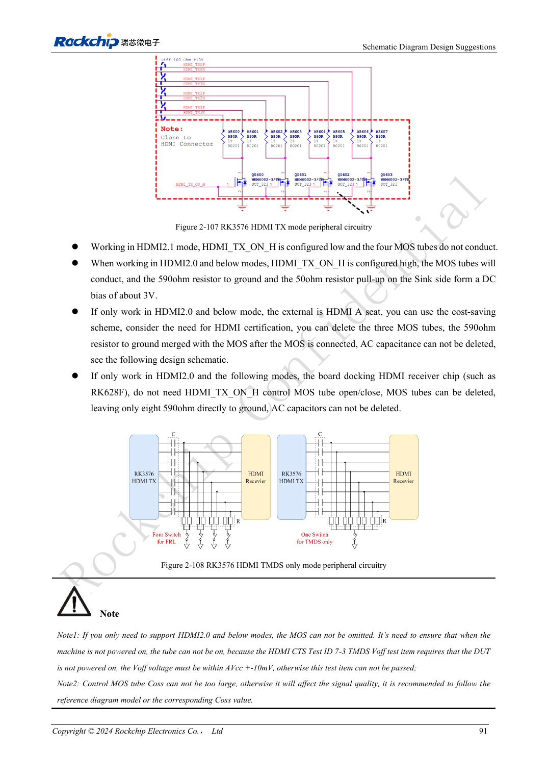
English original · PDF 110 · 2-107
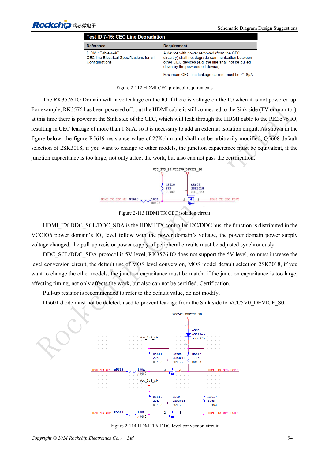
English original · PDF 113 · 2-113
ArmSoM development path
CM5 reduces repeated compute-core design on custom carriers; Sige5 provides a starting point for software and peripheral evaluation. Verify exposed interfaces, connector pins, voltages and image support in board documentation rather than inferring them from SoC features.