
Based on the Chinese and English RK3576 Hardware Design Guide V1.1 (2024-05-28), for SoC-board design. CM5 carriers must follow the module interface; Sige5 can establish a software/peripheral baseline. This guide does not prescribe one SDK/BSP or kernel for every product; verify each board. Values are source references, not ArmSoM measurements.
RK3576_Hardware_Design_Guide_V1.1_20240528_EN.pdf · §2.3.8.2, §2.3.8.4–6; MIPI/RGB PCB
Select a panel by interface, not resolution alone
MIPI TX offers four DPHY lanes up to 2.5Gbps/lane or three CPHY trios up to 1.7Gsps; the guide lists 2560×1600@60 capability. Shared DCPHY TX/RX must use the same mode. RGB/BT1120 uses VCCIO5 at the panel-compatible 1.8/3.3V. RGB666/RGB565 mappings use upper data bits; do not assume wiring starts at D0.
Start with panel and backlight off
Use controllable panel power, off by default. Backlight EN/PWM should default low with external pull-downs to avoid flashes. Rate boost inductors, diodes and capacitors for operating and open-load conditions; use a 1% current-setting FB resistor. Touch I2C uses 2.2kΩ pull-ups to VCC3V3_TP, preferably on a dedicated bus. Shared buses require address, sequencing and back-power checks.
Keep DPHY and CPHY constraints distinct
Route DPHY as pairs and CPHY as trios, not ordinary differential pairs. Include FPC, connectors, ESD and test points in the channel; keep test stubs short. Validate cold boot, brightness control, sleep/wake, touch interrupts and prolonged display operation. Panel initialization follows the actual panel, not only the SoC model.
Design parameters and review table
| Item | Source reference |
|---|---|
| DPHY Zdiff | 100Ω ±10% preferred |
| DPHY intra-pair / CLK-data | <6mil / <12mil |
| CPHY Zsingle | 50Ω ±10% |
| CPHY intra-trio / inter-trio | <6mil / <100mil |
| DPHY / CPHY length | <6inch / <5inch |
Source figures
The reference pages below contain the relevant circuit or timing figures; click for full resolution. Designators and component values belong to the reference design, not an ArmSoM product schematic.
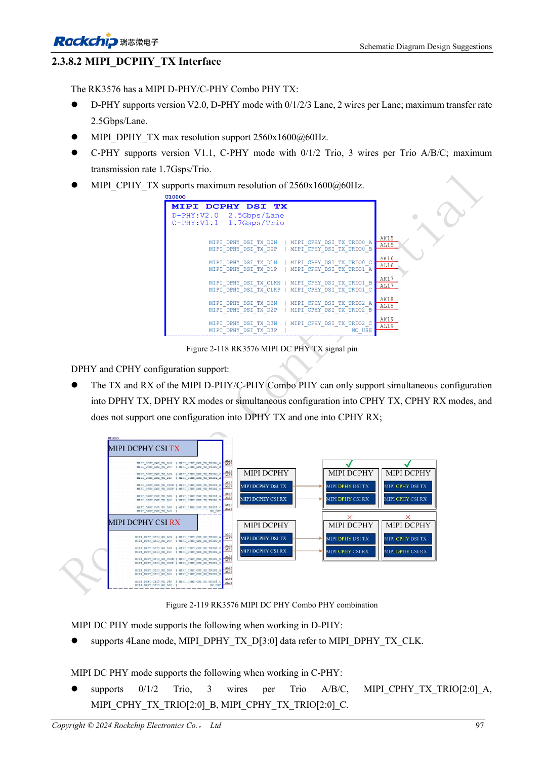
English original · PDF 116 · 2-118
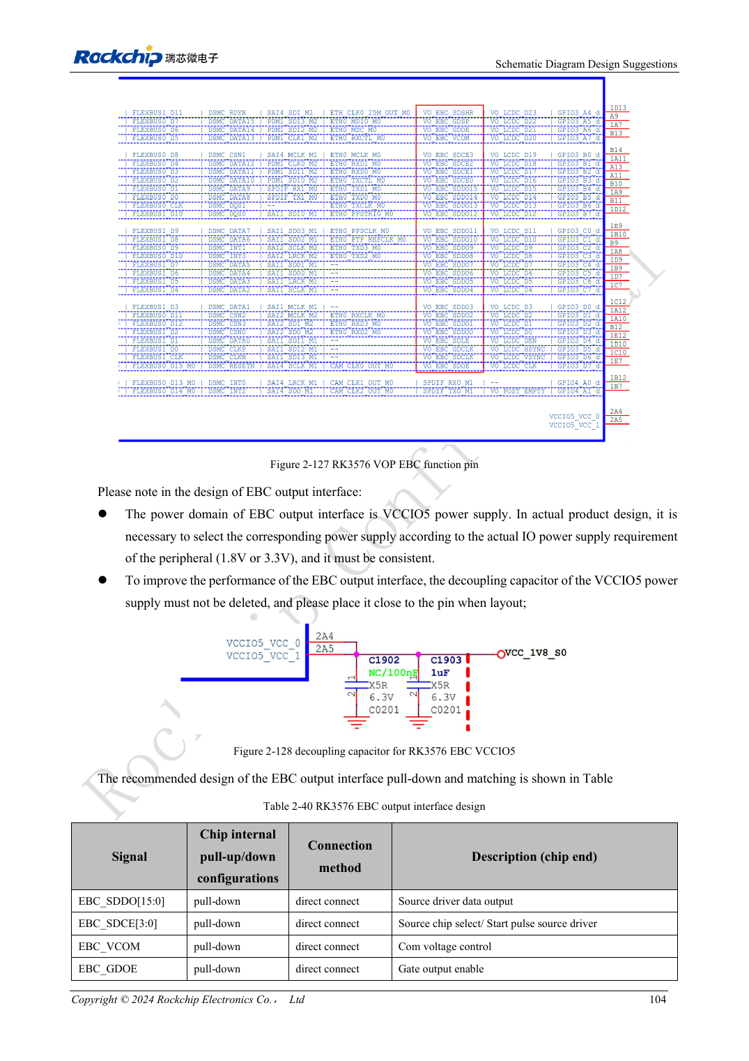
English original · PDF 123 · 2-127
ArmSoM development path
CM5 reduces repeated compute-core design on custom carriers; Sige5 provides a starting point for software and peripheral evaluation. Verify exposed interfaces, connector pins, voltages and image support in board documentation rather than inferring them from SoC features.