
ArmSoM platform reference preserving the full Rockchip technical source. Verify board, SoC, SDK/BSP, kernel and audio hardware/libraries; no universal board support is claimed. Source results/logs are not ArmSoM tests. No commands or hardware validation performed.
Source V1.7.0 explains VQE interfaces, modules and parameters; scope is all series/general. Chinese uses Chinese figures; English/Russian/German use English originals. Tests took place in the Rockchip studio and are source-reference results only.
1. Overview
1.1 Audio algorithm features
Multi-microphone array algorithm, including echo cancellation AEC, beamforming BF, speech noise reduction ANR, automatic gain AGC, etc. Mainly includes the following application scenarios: Echo cancellation AEC is used to eliminate the sound played by the speaker collected by the microphone Beamforming BF is used to enhance the voice and suppress coherent noise and environmental noise Speech noise reduction ANR is used to eliminate the environmental noise collected by the microphone Automatic gain AGC is used to enhance the voice level signal
2. Audio algorithm description
Multi-microphone acoustic processing mainly completes echo cancellation and voice enhancement tasks
2.1 Audio algorithm module description
The complete algorithm includes the process modules as shown in Figure 1, including the following parts:
2.1.1 Auxiliary modules
These modules include high pass filter, pre-emphasis, de-emphasis and other modules. Among them, the high pass filter module is used to filter out low-frequency circuit noise, and the pre-emphasis is used to enhance the high-frequency energy of the voice and enhance the high-frequency signal-to-noise ratio during the transmission process, and then restore it at the output end through de-emphasis.
2.1.2 AEC module
The AEC module includes the MDF module and the Delay module. The MDF module belongs to the linear echo cancellation algorithm and is used to eliminate echoes The Delay module is a delay estimation module, which is used to estimate the delay between the echo signal and the microphone signal
2.1.3 Beamforming module
The Beamforming (hereinafter referred to as BF) module includes FAST_AEC module, WAKEUP module, ANR module, Dereverb module, AES module, AGC module, CNG module, DTD module, Howling module, EQ module and DOA module. FAST_AEC module: linear echo cancellation algorithm, used to suppress residual echo WAKEUP module: RK customized wake-up, mainly completes the specific wake-up word to wake up the machine ANR module: noise reduction module, used to suppress environmental noise, wind noise, impact noise Dereverb module: dereverberation module, used to eliminate environmental reverberation AES module: residual echo cancellation algorithm, used to further suppress residual echo; GSC module: beam module, which is enabled by default when the input is multi-microphone audio. When Fix/GSC/CHN_SELECT is additionally enabled, fixed direction beam/beam post- filtering/customized extended mic is enabled; AGC module: automatic gain module, used to control the voice level signal CNG module: comfort noise module, used to add comfort noise DTD module: double talk detection module, used to detect the voice call status Howling module: howling module, used to remove the howling generated by self-excitation; EQ module: equalizer module, used to adjust the frequency band gain; DOA module: sound source localization module, used to locate the direction of the sound source; AINR module: AI noise reduction module, used to suppress noise other than human voice;
2.2 Audio algorithm process
The multi-microphone array algorithm provides two different voice channels.
2.2.1 Wake-up process
This process performs machine response and positioning through wake-up, and outputs the audio of the wake-up person’s location. The specific process is shown in Figure 1.

Figure 1 Wake-up process system block diagram
-
After the array collects array information, the linear echo is first eliminated through the AEC module, and the BF built-in FAST_AEC performs further echo suppression;
-
The voice is enhanced by the fixed beam output;
-
The Derevb module is connected to remove residual reverberation;
-
The sound source is located through the Wakeup wake-up module;
-
The located voice is sent to the GSC post-processing module for post-filtering (Note: the blue arrow is the cloud recognition process, and the located voice is directly sent to the AGC output);
-
The processed voice is then sent to the ANR module for further noise reduction;
-
Finally, it is sent to the AGC module for voice gain and sent to the remote end for communication.
2.2.2 Calling process
This process does not wake up. Except for the Wakeup module, the other modules are similar to the wake-up process. The specific process is shown in Figure 2.
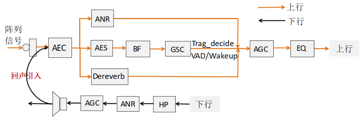
Figure 2 Calling process system block diagram
-
After the array collects array information, the linear echo is first eliminated through the AEC module;
-
The ANR/AINR, Derevb, and AES modules are connected to perform noise, reverberation estimation, and residual echo elimination respectively;
-
The voice enhanced by the beam output supports sound source localization and directional sound pickup;
-
Finally, it is sent to the AGC and EQ modules for voice gain and sent to the remote end for the call.
2.3 Audio algorithm running effect display
2.3.1 AEC module effect
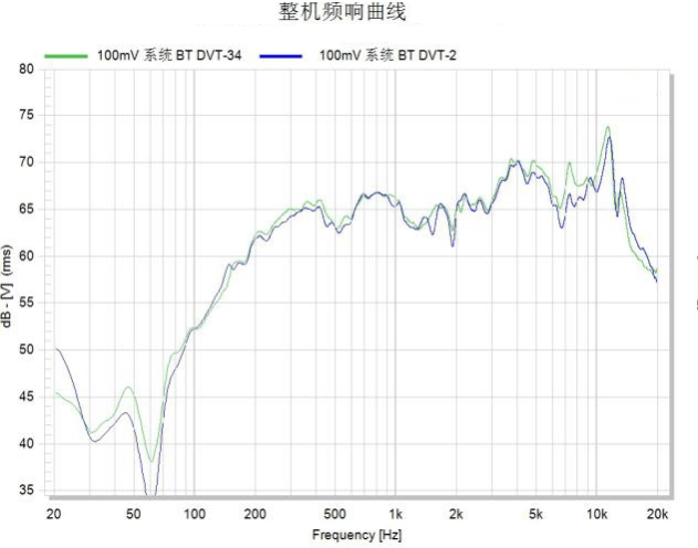
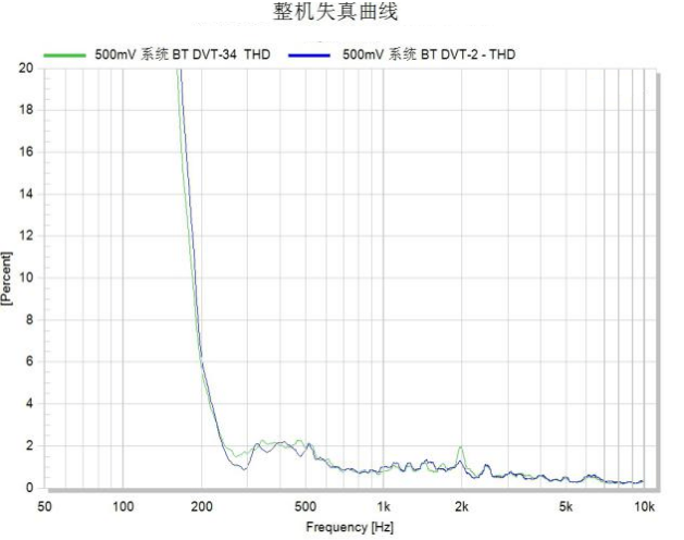
The multi-microphone call algorithm provides two different voice channels. The following are the effects produced by the two different channels. Note that the test audio uses the WV2215 speaker, the microphone uses the MSM261D4030H1CPM, and the test environment is the Rockchip studio. The frequency response and distortion curves of the speaker are as follows: Figure 3 WV2215 frequency response and distortion curve
The algorithm effect statistics are performed using the wake-up plus noise method. The left channel is the original input and the right channel is the output after algorithm processing. Among them, the left figure is the frequency domain figure, and the right figure is the time domain statistical result in the pure noise range. Linear echo cancellation effect The following is the result of linear echo processing. It should be noted that the audio is not measured in a professional acoustic environment and there is environmental noise. The result is for reference only.
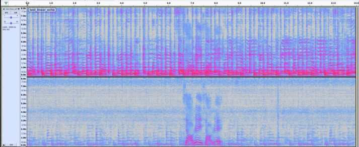
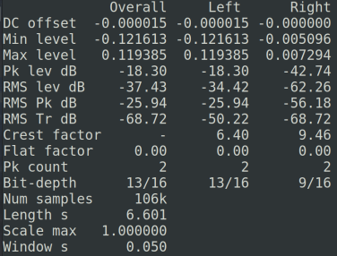
Figure 4 Block diagram of linear echo cancellation system In this scenario, the echo cancellation is around 30dB on average. Nonlinear echo cancellation effect The following is the result of nonlinear echo processing. It should be noted that the audio is not measured in a professional acoustic environment, and the results are for reference only.
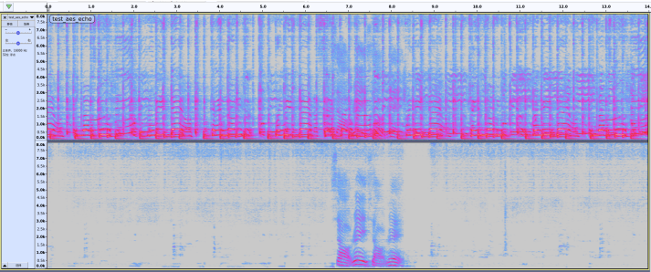
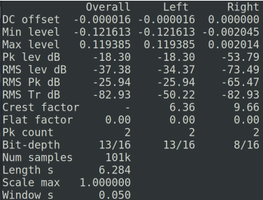
Figure 5 Nonlinear echo cancellation system block diagram In this scenario, the echo cancellation is around 40dB on average.
2.3.2 BF module effect
The following is an interference test. The test site is Rockchip Studio. The decibel value at 1m from the test sound source is 70dB. The test sound source is 5m away from the microphone array. The decibel value at 1m from the interference sound source is 64dB. The interference sound source is 1m away from the microphone array: Wake-up process effect The following is a wake-up test in a general environment. The results are for reference only:
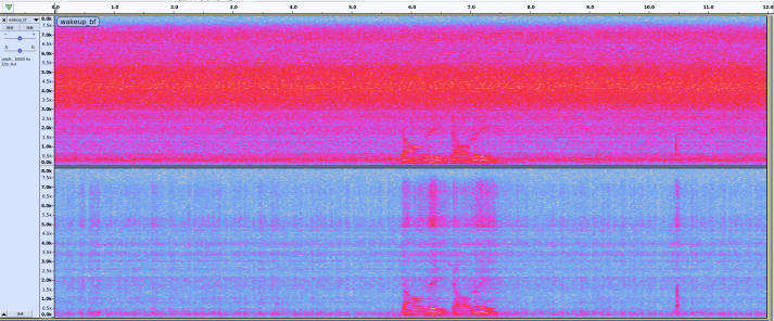
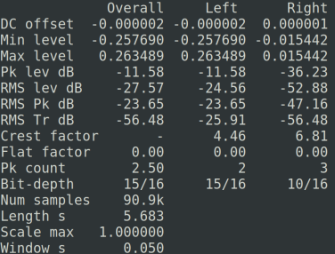
Figure 6 Wake- up process effect diagram In this scenario, the background noise elimination is around 28dB on average. Note: Voice wake-up only uses fixed beams to avoid voice damage. Calling process effect The following is a call test in a general environment, the results are for reference only:
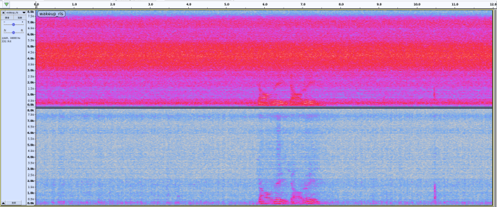
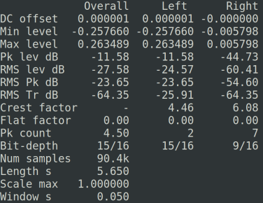
Figure 7 Call process effect diagram In this scenario, the average background noise elimination is about 36dB.
3. Audio algorithm interface call description
The calling process of this library is as follows:
-
Setting parameters: This step is used to set the audio parameters open to the microphone algorithm. Among them, the setting of AEC related parameters needs to be adjusted according to the product audio cavity, device characteristics and usage requirements. When using, it is necessary to set parameters according to the characteristics of each product. The default parameters can be used for initial integration, and then the parameters are adjusted according to the effect. The parameter setting needs to be adjusted through the rkaudio_preprocess.h file, and the file path name is used as the input parameter for initialization.
-
Initialization:
This step is used after the call is opened, before processing the sound signal frame by frame. The initialization interface function is called rkaudio_preprocess_init, and the specific call is as follows:
st_ptr = rkaudio_preprocess_init(mSampleRate, mBitPerSample, num_src_channel,
num_ref_channel, ¶m);
Among them, mSampleRate supports 8kHz, 16kHz, 24kHz, 32kHz, 44.1kHz, and 48kHz sampling rates, mBitPerSample audio bit depth is 16bit, num_src_channel is the number of mic channels, num_ref_channel is the number of resampled channels, and param is an input parameter. This parameter is configured through rkaudio_preprocess.h and will be described in detail later. Initialization completes the initialization of the algorithm’s internal parameters and related memory requests. If the initialization is successful, the st_ptr structure is returned. If the initialization fails, the structure will be NULL.
- Frame processing: This step is to process the call voice signal in real time. The unit is frame. When each frame is fixed at 16ms and the sampling rate is 16k samples, each frame contains 256 samples. Frame processing includes the interface function rkaudio_preprocess_short, and the specific call is as follows:
out_size = rkaudio_preprocess_short(st_ptr, (short*)in, out, in_size / 2, &is_wakeup);
Among them, st_ptr is the structure generated after initialization, in is the input audio, the unit is byte, out is the output audio, the unit is short, and in_size is the number of bytes read in one frame, that is, 256 * num_channel * 2 .
- Destruction and release: This step is used to release the algorithm memory variables after the call ends. The interface functions are rkaudio_preprocess_destory(st_ptr) and rkaudio_param_deinit(¶m).
4. Audio algorithm parameter debugging instructions
The multi-microphone array algorithm is configured through the rkaudio_preprocess.h file.
4.1 Global module parameter settings
The parameter settings are mainly divided into AEC module and BF module, among which the AEC module is configured through the rkaudio_aec_param_init() function, and the BF module is configured through the rkaudio_preprocess_param_init() function. The following is the basic setting for the number of various channels of input audio.
#define NUM_CHANNEL 4      /* Set the total number of channels, that is, the sum of mic
channels and recollection channels */
#define NUM_REF_CHANNEL 2  /* Set the number of recollection channels, here set 2
recollection channels */
#define NUM_DROP_CHANNEL 0 /* Set the number of recollection channels not to be processed,
set to 0 for no discard, set to N (N>0) for discarding the last N channels of the
recollection path */
#define REF_POSITION 0     /* Recollection position, 0 for the recollection channel at the
front of the mic data, 1 for the back */
static short Array[NUM_CHANNEL] = { 0, 1, 2, 3}; /* Set the channel order for irregular
microphone adjustment */
4.2 AEC module parameter settings
The AEC module is configured through the rkaudio_aec_param_init() function, and the main parameters are as follows: The switches of each submodule are mainly controlled by model_aec_en, mainly including: EN_DELAY, EN_ARRAY_RESET. For details, please see the code comments below.
param->pos              /* The position of the acquisition channel, assigned by the macro
REF_POSITION */
param->drop_ref_channel /* The number of acquisition channels not processed, assigned by the
macro NUM_DROP_CHANNEL */
param->model_aec_en     /* Set to 0 to disable submodules other than linear AEC, set
EN_DELAY to enable delay estimation, soft acquisition must be enabled, set EN_ARRAY_RESET to
enable input audio channel order reordering */
param->delay_len        /* The default hard acquisition delay point when delay estimation is
not enabled, and the starting delay estimation point when delay estimation is enabled */
param->look_ahead       /* The length of the cached microphone data, unless it is known that
the acquisition microphone signal is later than the acquisition signal, it can be
configured, otherwise it is set to 0 by default */
param->Array_list       /* Configure the order of audio channels, assigned by the array
Array */
param->filter_len       /* Configure the linear AEC filter length. The longer the setting,
the more accurate the echo estimation, but the slower the convergence speed and the greater
the computing power. Generally, it can be configured to 2/4/6/8 */
param->delay_para = rkaudio_delay_param_init() /* Delay estimation submodule parameter
setting */
4.3 Delay estimation submodule parameter settings
The delay module is configured through the rkaudio_delay_param_init() function. The main parameters are as follows:
param->MaxFrame     /* The maximum estimated number of frames for delay estimation. It is
recommended to set it to 16 in general scenarios */
param->LeastDelay   /* The minimum estimated number of frames for delay estimation. It is
recommended to set it to 0 when MaxFrame is not particularly large */
param->JumpFrame    /* The initial number of skipped frames. It is generally set to 12 */
param->DelayOffset  /* The number of offset frames, which is used to prevent the microphone
signal from being delayed later than the collected signal due to excessive delay estimation.
It is generally set to 1 */
param->MicAmpThr    /* The minimum energy threshold of the mic end. If it is lower than this
value, the delay estimation result will not be updated. It is generally set to 50 */
param->RefAmpThr    /* The minimum energy threshold of the ref end. If it is lower than this
value, the delay estimation result will not be updated. It is generally set to 50 */
param->StartFreq    /* The frequency of the start frequency band of delay estimation.
Generally, the frequency band where voice is concentrated is selected. It is adjusted
according to the actual sound reception effect. It is generally set to 500 */
param->EndFreq      /* The frequency of the delay estimation termination band, generally
select the voice concentration band, adjust according to the actual sound reception effect,
generally set to 4000 */
param->SmoothFactor /* Smoothing coefficient, generally set to [0.95,1). The higher the
delay estimation result, the more stable it is, and the lower the delay estimation result,
the faster it is updated. Generally set to 0.97/0.99 */
4.4 BF module parameter settings
The BF module submodules mainly include: EN_Fastaec, EN_Wakeup, EN_Dereverberation, EN_AES, EN_Agc, EN_Anr, EN_STDT, EN_CNG, EN_EQ, EN_HOWLING, EN_DOA, EN_WIND, EN_AINR, etc. For details, please see the code comments below.
typedef enum RKPreprocessEnable_
{
    EN_Fastaec = 1 << 0,         /* Linear residual echo cancellation module, this function
is used to further eliminate echo in the wake-up channel */
    EN_Wakeup = 1 << 1, /* Wake-up module */
    EN_Dereverberation = 1 << 2, /* De-reverberation module */
    EN_Nlp = 1 << 3,             /* Non-linear residual echo cancellation module, this
function is used to further eliminate echo in the call channel (this module has been
deprecated) */
    EN_AES = 1 << 4,             /* Non-linear residual echo cancellation module */
    EN_Agc = 1 << 5,             /* Automatic gain control module */
    EN_Anr = 1 << 6,             /* Noise suppression module */
    EN_GSC = 1 << 7,             /* Beam post-filter module, used to further eliminate
noise, whether to open or not depends on the actual effect */
    GSC_Method = 1 << 8,         /* If closed, GSC uses the LMS method, and if opened, GSC
uses the RLS method. The computing power of RLS is higher than that of the LMS algorithm */
    EN_Fix = 1 << 9,             /* Enable fixed direction beam */
    EN_STDT = 1 << 10,           /* Single and double talk detection module */
    EN_CNG = 1 << 11,            /* Comfort noise module */
    EN_EQ = 1 << 12,             /* EQ adjustment module */
    EN_CHN_SELECT = 1 << 13,     /* For customized expansion of MIC demand scenarios */
    EN_HOWLING = 1 << 14,        /* Howling removal module, whether to open or not depends
on the actual scenario requirements */
    EN_DOA = 1 << 15,            /* Sound source localization module, used to estimate the
direction of the sound source, whether to open it depends on the actual scene requirements
*/
    EN_WIND = 1 << 16,           /* Wind noise removal module, whether to open it depends on
the actual scene requirements */
    EN_AINR = 1 << 17,           /* AI noise reduction module, if this module is turned on,
the ANR module will be forced to close */
} RKPreprocessEnable;
The BF module is configured through the rkaudio_preprocess_param_init() function. The main parameters are as follows:
param->model_bf_en /* Submodule switch. Setting it to 0 means that the bf module does not
turn on any module in the non-multi-microphone case. When it is in the multi-microphone
case, the beam module will be run by default. The remaining submodules can be turned on and
off as needed */
param->Targ = 0; /* When EN_Fix is turned on, set the pickup direction */
param->ref_pos = REF_POSITION; /* The position of the acquisition channel, assigned by the
macro REF_POSITION */
param->num_ref_channel = NUM_REF_CHANNEL; /* The total number of acquisition channels,
assigned by the macro NUM_REF_CHANNEL */
param->drop_ref_channel = NUM_DROP_CHANNEL; /* The number of acquisition channels not
processed, assigned by the macro NUM_DROP_CHANNEL */
param->anr_para = rkaudio_anr_param_init_tx();        /* ANR module parameter configuration
*/
param->dereverb_para = rkaudio_dereverb_param_init(); /* De-reverberation module parameter
configuration */
param->aes_para = rkaudio_aes_param_init();           /* AES module parameter configuration
*/
param->dtd_para = rkaudio_dtd_param_init();           /* DTD module parameter configuration
*/
param->agc_para = rkaudio_agc_param_init();           /* AGC module parameter configuration
*/
param->cng_para = rkaudio_cng_param_init();           /* CNG module parameter configuration
*/
param->eq_para = rkaudio_eq_param_init();             /* EQ module parameter configuration
*/
param->howl_para = rkaudio_howl_param_init_tx();      /* Howl module parameter configuration
*/
param->doa_para = rkaudio_doa_param_init();           /* DOA module parameter configuration
*/
4.5 ANR module parameter settings
The noise reduction module is used for voice noise reduction and environmental noise elimination. It is configured through the rkaudio_anr_param_init() function:
param->noiseFactor /* Noise estimation level, generally in the range of [0.5f, 1.5f]. The
larger the value, the cleaner the noise elimination */
param->swU /* Noise estimation frame time slice, generally in the range of [2, 20]. The
larger the setting, the more accurate the estimation of stable noise, and the slower the
convergence of sudden noise; on the contrary, the faster the convergence of sudden noise,
but it is easy to cause voice over-elimination */
param->PsiMin /* Voice existence probability judgment threshold, in the range of [0.0f,
1.0f]. The larger the setting, the stronger the noise elimination effect */
param->PsiMax /* Voice existence probability judgment threshold, in the range of [0.0f,
1.0f]. The larger the setting, the stronger the noise elimination effect */
param->fGmin /* Minimum noise elimination value, value range [0.0f, 1.0f], the smaller the
setting, the stronger the noise elimination effect */

param->Sup_Freq1 /* Constant frequency noise suppression point 1, value range [0, 1/2*sample
rate], always suppress the set point noise */
param->Sup_Freq2 /* Constant frequency noise suppression point 2, value range [0, 1/2*sample
rate], always suppress the set point noise */
param->Sup_Energy1 /* Energy threshold corresponding to constant frequency noise suppression
point 1, generally 100000, when the frequency energy exceeds this value, the constant
frequency noise estimate will be updated */
param->Sup_Energy2 /* Energy threshold corresponding to constant frequency noise suppression
point 1, generally 100000, when the frequency energy exceeds this value, the constant
frequency noise estimate will be updated */

param->InterV /* Take the frame interval, generally in the range of [2,20]. The larger the
setting, the smoother the estimated noise, similar to the swU function */
param->BiasMin /* Noise compensation, generally in the range of [1.0f, 2.0f]. The larger the
setting, the stronger the noise elimination effect */
param->UpdateFrm /* Fast convergence length, generally set to 15, fast convergence in the
first 15 frames */
param->NPreGammaThr /* Pure noise probability estimation threshold, generally in the range
of (3.0f, 5.0f). The larger the setting, the stronger the noise elimination effect */
param->NPreZetaThr /* Pure noise probability estimation threshold, generally in the range of
(1.0f, 3.0f). The larger the setting, the stronger the noise elimination effect */
param->SabsGammaThr0 /* Speech non-existence probability estimation threshold, generally in
the range of (0.5f, 1.5f). The larger the setting, the stronger the noise elimination effect
*/
param->SabsGammaThr1 /* Threshold for probability estimation of speech absence, generally in
the range of (2.f, 4.0f), the larger the setting, the stronger the noise elimination
effect*/
param->InfSmooth /* Input signal smoothing coefficient, in the range of (0.0f, 1.0f) */
param->ProbSmooth /* Speech presence probability smoothing coefficient, in the range of
(0.0f, 1.0f) */
param->CompCoeff /* Noise compensation, generally in the range of [1.0f, 2.0f], for
frequency bands below the average noise estimate, compensation is performed, the larger the
setting, the stronger the noise elimination effect */
param->PrioriMin /* Priori signal-to-noise ratio minimum value, in the range of (0.0f,
0.5f), the larger the setting, the weaker the noise elimination effect */
param->PostMax /* Posteriori signal-to-noise ratio maximum value, generally set to 40 */
param->PrioriRatio /* Priori signal-to-noise ratio smoothing coefficient, value range (0.0f,
1.0f), the larger the setting, the stronger the noise elimination effect */
param->PrioriRatioLow /* Priori signal-to-noise ratio smoothing coefficient, value range
(0.0f, 1.0f), the larger the setting, the stronger the noise elimination effect */
param->SplitBand /* Split-band index, value range [0, 32], for the priori signal-to-noise
ratio below this index, use PrioriRatioLow for smoothing, otherwise use PrioriRatio */
param->PrioriSmooth /* Priori signal-to-noise ratio smoothing coefficient, value range
(0.0f, 1.0f), the larger the setting, the stronger the noise elimination effect */
param->TranMode /* Impulse noise switch, set to 0 for off, set to 1 for using the detection
elimination method, set to 2 for using the estimation elimination method */
4.6 AINR module parameter settings
Compared with the classic ANR algorithm, the AINR module has been enhanced to eliminate various non- steady-state noises (such as wind noise, impact noise, etc.). The sound after AI noise reduction is more natural. It complements the traditional ANR and can work independently or simultaneously with collaborative noise reduction.
param->mode = 2; /* Post-processing mode, optional modes 1 and 2, default mode 2. Mode 1 has
better voice protection and smoothing than mode 2, and is suitable for far-field small voice
scenarios; mode 2 has a greater noise reduction depth than mode 1, and is suitable for large
background noise scenarios */
param->alpha1 = 0.35; /* Smoothing coefficient, generally set to 0.35, value range [0,0.65]
*/
param->mini_gain = 0.01; /* Ambient sound retention ratio, value range [0.0,1.0], generally
set range [0.005,0.1], the larger the value, the greater the ambient sound retention */
param->pregain = 1.0; /* Pre-gain before the input audio is sent to AINR, the default value
is 1.0, and the value can be increased or decreased when the front-end gain is too low or
too high, resulting in abnormal effects */
/* The following are reserved parameters for expansion */
param->alpha2 = 0; /* Reserved parameters */
param->preserve1 = 0.0; /* Preserve parameter. When mode==1, this parameter is used as the
noise threshold. The larger the value, the more noise is eliminated. The recommended value
is: 1.0 */
param->preserve2 = 0.0; /* Preserve parameter. When mode==1, this parameter is used as the
voice threshold. The smaller the value, the more voice is preserved. The recommended value
range is: [4,6] */
param->preserve3 = 0; /* Preserve parameter */
param->preserve4 = 0; /* Preserve parameter */
4.7 De-reverberation module parameter settings
The de-reverberation module is used for reverberation elimination. The module is configured through rkaudio_dereverb_param_init():
param->rlsLg /* RLS filter order, used for wake-up module reverberation. Within a certain
range, the larger the order, the stronger the reverberation effect and the greater the
computing power consumption. The recommended value is: 4 */
param->curveLg /* Distribution curve order, used for call module reverberation. The larger
the order, the stronger the reverberation effect and the easier it is to over-cancel. The
recommended value is: 10 */
param->delay /* RLS filter delay, which determines the degree of early reverberation
retention. The recommended value is: 2 */
param->forgetting /* RLS filter forgetting factor. The smaller the factor, the stronger the
rls reverberation ability and the easier it is to over-cancel. The recommended range is:
0.98-0.999 */
param->T60 /* Reverberation time estimation value (unit: s). The larger the value, the
stronger the reverberation ability, but the easier it is to over-eliminate. The recommended
value is 0.68 for low reverberation scenes and 1.5 for medium and high reverberation scenes.
*/
param->coCoeff /* Mutual coherence adjustment coefficient to prevent over-elimination. The
smaller the value, the stronger the ability. The recommended value is 2 for low
reverberation scenes and 1 for medium and high reverberation scenes. */
4.8 AES module parameter settings
The AES module is used for nonlinear processing. This module is configured via rkaudio_aes_param_init().
param->Beta_Up /* Rise speed, the larger the value, the stronger the nonlinear suppression,
the recommended range is 0.001-0.01 */
param->Beta_Down /* Decline speed, the larger the value, the weaker the nonlinear
suppression, the recommended range is 0.001-0.01 */
param->Beta_Up_Low /* Low frequency rise speed, characteristics and values ••are the same as
Beta_Up */
param->Beta_Down_Low /* Low frequency fall speed, characteristics and values ••are the same
as Beta_Down */
param->low_freq /* Low frequency segment */
param->high_freq /* High frequency segment */
param->THD_Flag /* Set to 1 to enable harmonic distortion suppression, set to 0 to disable
*/
param->HARD_Flag /* Set to 1 to enable Hard mode, which is stronger for echo cancellation
suppression, but may also cause voice over-cancellation */
int i, j;

/**
 * The 3 columns correspond to the low frequency segment, the middle frequency segment, and
the high frequency segment (set by the low_freq and high freq above
 * The first row indicates the minimum value of the residual echo ratio of each frequency
band. The recommended value range is [1.0f, 5.0f]. The larger the setting, the stronger the
echo cancellation effect
 * The second row indicates the ratio of residual echo elimination of each frequency band.
The recommended value range is [1.0f, 3.0f]. The larger the setting, the stronger the echo
cancellation effect
 */
param->LimitRatio[2][3]
/**
 * Harmonic suppression frequency band, up to 4 frequency bands can be set. If not needed,
this row can be set to 0
 * Each row represents a frequency band. The first column indicates the starting point of
the frequency band, and the second column indicates the ending point of the frequency band.
The value range is [0,1/2*sample rate]
 */
param->ThdSplitFreq[4][2]

/**
 * The degree of harmonic suppression corresponds to the four frequency bands in the table
above, and the corresponding elimination ratio is configured. When there are all 0 rows
above, the settings of the corresponding rows in the table will also be invalid.
 * From the first column to the last column, they represent the ratio of the corresponding
fundamental frequency to be eliminated when the frequency band may become the second to
eleventh harmonics. The generally recommended value range is
 * [0.001f, 1.0f]. The larger the setting, the stronger the elimination effect.
 */
param->ThdSupDegree[4][10]

/**
 * The frequency band configured as Hard mode and the frequency band for calculating the
average gain. The first column indicates the start and the second column indicates the end.
The value range is
 * [0, 1/2*sample rate]. The frequency band configured as Hard mode can be set to a maximum
of 4. The last line is the frequency band for calculating the average gain.
 * This frequency band will be used in the next parameter HardThreshold.
 */
param->HardSplitFreq[5][2]

/**
 * The threshold for turning on Hard mode. The 4 thresholds correspond to the 4 frequency
bands configured in the previous parameter.
 * Use the average gain frequency band to compare with the threshold configured by this
parameter. When the average gain is lower than the threshold, the corresponding frequency
band will turn on the Hard mode.
 */
param->HardThreshold[4]
4.9 AGC module parameter settings
AGC module is used to enhance speech, and is configured through rkaudio_agc_param_init() function:
param->attack_time = 400.0; /* Recommended range: 20~600ms. Trigger time, that is, the time
required for AGC gain to rise */
param->release_time = 400.0; /* Recommended range: 20~600ms. Release time, that is, the time
required for AGC gain to fall */
param->max_gain = 30.0; /* Recommended range: 0~50dB. Maximum gain, also the linear gain */
param->max_peak = -3.0; /* Value range: 0~-87dB. The maximum energy of the output speech
after AGC processing */
param->fRth0 = -65.0f; /* Value range: 0~-87dB. Noise gate threshold, speech below this
value will not be gained */
param->fRth1 = -60.0f; /* Value range: 0~-87dB. Energy dB threshold at the end of expansion
segment, speech above this value is gained at max_gain */
param->fRth2 = -35.0f; /* Value range: 0~-87dB. Energy dB threshold at the start of
compression segment, speech gain above this value gradually decreases to 0dB */
Note 1: The compression segment must meet the following conditions: fRth2 + max_gain must be less than 0dB and less than max_peak, otherwise clipping will occur. Note 2: The above parameters are valid parameters for AGC debugging, and all other parameters are obsolete. Since previous versions may keep using the old obsolete parameters for compatibility, subsequent parameter versions will gradually delete the obsolete parameters. Therefore, this is specially stated here.
4.10 CNG parameter setting
Comfortable noise (CNG) parameter setting is used to add comfortable white noise during the call. It only exists in the recording process, and this module is usually turned off.
param->fSmoothAlpha /* Value range: 0.0f~1.0f, apply comfort noise smoothness, default 0.92
*/
param->fSpeechGain /* Value range: 0.0f~1.0f, apply comfort noise speech texture simulation
degree, default 0.3 */
param->fGain /* Recommended range: 0~50dB, apply comfort noise amplitude ratio, default 2 */
param->fMpy /* Recommended range: 0~50dB, white noise random number generation amplitude,
default 5 */
4.11 DTD module parameter setting
DTD parameter setting is used to determine whether the voice is in a single-speaker or dual-speaker state.
param->ksiThd_high = 0.70f /* Single-speaker and double-speaker judgment threshold, ceil
threshold, above this threshold, it is judged as single-speaker */
param->ksiThd_low = 0.50f; /* floor threshold, below this threshold, it is judged as single-
speaker */
Note: This value is the starting threshold, and the current algorithm uses adaptive update.
4.12 Recommended parameter example
The recommended parameters for wakeup are as follows:
param->model_bf_en = EN_Wakeup | EN_Fastaec | EN_STDT | EN_Agc;
The recommended parameters for voice calls are as follows:
param->model_bf_en = EN_Fastaec | EN_STDT | EN_AES | EN_Anr | EN_Dereverberation | EN_Agc;