
Platform reference: vendor RK-KF-YF-096, Chinese V2.4.0 and English V2.4.1, covering Rockchip non-MCU SoCs and Linux 4.4+ BSPs. Verify the particular SoC, SDK/BSP, kernel patches, controller instance, PHY/IOMUX, power and board circuitry. Matching ArmSoM boards are not confirmed; no hardware validation was performed. Commands, waveforms and performance claims are vendor examples, not ArmSoM measurements. The Chinese body retains its source and adds English-only information; EN/RU/DE use the English body plus Chinese-only additions. Differing source examples are not silently substituted: the alternate-source code appendix preserves unique examples. ZH uses Chinese figures; EN/RU/DE use English figures, some of which still contain Chinese labels.
1. Overview
1.1 RK USB Controllers Solution
Rockchip SoC usually has several USB controllers built in, and different controllers are independent of each other. Please get detailed information in the chip TRM. Because some USB controllers have limitations on usage, it is important to clarify the requirements of the scheme and the limitations of the controller before determining the design scheme of USB. The built-in USB controllers of each chip are shown in Table 1-1. Table 1-1 USB Controllers List
| Chip | USB 2.0 HOST (EHCI&OHCI) |
USB HSIC (EHCI) |
USB 2.0/3.0 OTG (DWC3/xHCI) |
USB 2.0 OTG (DWC2) |
|---|---|---|---|---|
| RK3399Pro | 2 | 1 | 2 | 0 |
| RK3399 | 2 | 1 | 2 | 0 |
| RK3368 | 1 | 1 | 0 | 1 |
| RK3366 | 1 | 0 | 1 | 1 |
| RK3328 | 1 | 0 | 1 | 1 |
| RK3288 | 0 | 1 | 0 | 2 (HOST+OTG) |
| RK3228 | 3 | 0 | 0 | 1 |
| RK312X | 1 | 0 | 0 | 1 |
| RK3188 | 1 | 1 | 0 | 1 |
| RK30XX | 1 | 0 | 0 | 1 |
| RK3308 | 1 | 0 | 0 | 1 |
| RK3326 | 0 | 0 | 0 | 1 |
| RK1808 | 1 | 0 | 1 | 0 |
| RK1108 | 1 | 0 | 0 | 1 |
| PX30 | 1 | 0 | 0 | 1 |
| RV1103 | 0 | 0 | 1 (OTG 2.0) | 0 |
| RV1103B | 0 | 0 | 1 (OTG 2.0) | 0 |
| RV1106 | 0 | 0 | 1 (OTG 2.0) | 0 |
| RV1109 | 1 | 0 | 1 (OTG 2.0) | 0 |
| RV1126 | 1 | 0 | 1 (OTG 2.0) | 0 |
| RV1126B | 1 | 0 | 1 (OTG 3.0) | 0 |
| RK3506 | 0 | 0 | 0 | 2 x OTG 2.0 |
| RK3528 | 1 | 0 | 1 (OTG 3.0) | 0 |
| RK3562 | 1 | 0 | 1 (OTG 3.0) | 0 |
| RK3576 | 0 | 0 | 2 (OTG 3.0) | 0 |
| RK3566 | 2 | 0 | 2 (OTG 2.0 + Host 3.0) | 0 |
| RK3568 | 2 | 0 | 2 (OTG 3.0+ Host 3.0) | 0 |
| Chip | USB 2.0 HOST (EHCI&OHCI) |
USB HSIC (EHCI) |
USB 2.0/3.0 OTG (DWC3/xHCI) |
USB 2.0 OTG (DWC2) |
|---|---|---|---|---|
| RK3588 | 2 | 0 | 3 (2 x OTG 3.0 + 1 x Host 3.0) |
0 |
| RK3588S | 2 | 0 | 2 (1 x OTG 3.0 + 1 x Host 3.0) |
0 |
Note:
- In the table, the number N indicates that it supports N independent USB controllers.
- In the table, “EHCI/OHCI” indicates that the USB controller integrates the EHCI controller and OHCI controller. “DWC3/xHCI” indicates that the USB controller integrates the DWC3 controller and xHCI controller.
- RK3288 supports two independent DWC2 controllers. One DWC2 supports OTG function and the other DWC2 only supports Host function.
- RV1103/RV1106/RV1109/RV1126/RK3566 DWC3 controller only supports OTG 2.0, no support OTG 3.0, the maximal transfer rate is 480 Mb/s (High speed).
- The difference between the USB modules of RK3588 and RK3588S is that RK3588S doesn’t support Type-C1 (1 x USB 3.0 OTG controller + 1 x DP controller + 1 x USB3.0/DP combo PHY + 1 x USB 2.0 PHY).
- RK3588 and RK3588S Host 3.0 controller (USB30_2 interface) only support USB 3.0 and not downward compatible with USB 2.0.
- RV1103/RV1103B/RV1106 USB PHY don’t support OTG_ID and therefore not support OTG Device/Host mode switch automatically by hardware. If you want to switch OTG mode, please refer to the chapter USB Common Commands to switch OTG mode by software.
- The RK3506 supports two fully functional DWC2 OTG controllers, which can be applied to dual Device product forms, but only OTG0 supports BC1.2 charging detection and Device hot-plug disconnect detection. In addition, the RK3506 SDK’s hardware and software can support the use of GPIO to detect VBUS and ID voltage as an alternative to the conventional USB PHY VBUSDET and OTG_ID pins.
1.2 USB 2.0 Host
Compatible Specification Universal Serial Bus Specification, Revision 2.0 Enhanced Host Controller Interface Specification(EHCI), Revision 1.0 Open Host Controller Interface Specification(OHCI), Revision 1.0a Features Support high-speed(480Mbps), full-speed(12Mbps) and low-speed(1.5Mbps). The block diagram of the USB 2.0 Host controller is shown in Figure 1-1.
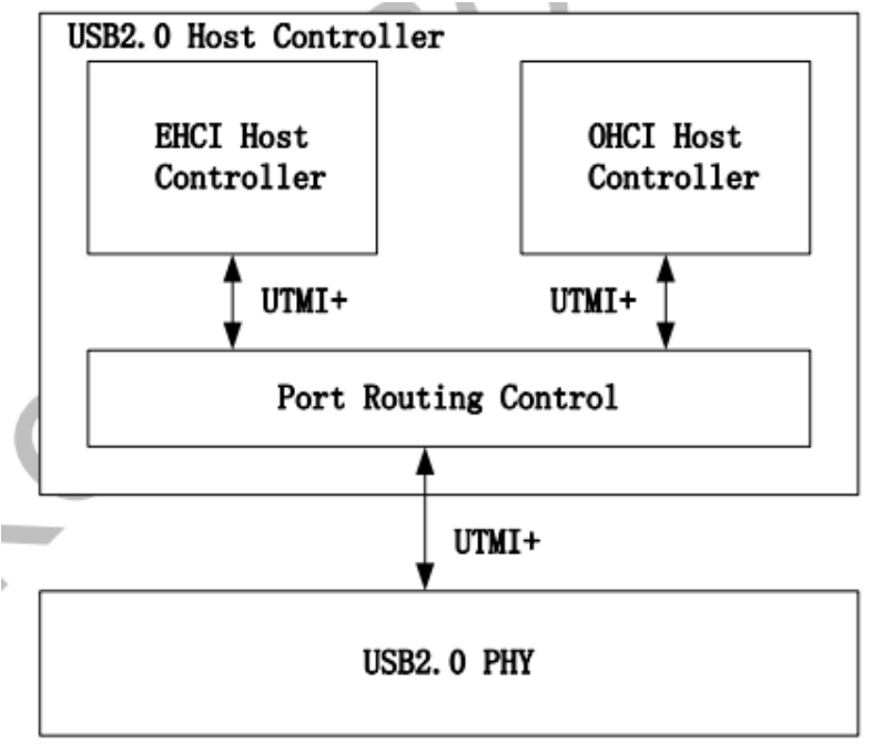
Figure 1-1 USB 2.0 Host Controller Block Diagram
1.3 USB 2.0 OTG
Compatible Specification Universal Serial Bus Specification, Revision 2.0 Features Supports Host mode and Device mode Support OTG ID detection, and automatically switch between Host mode and Device mode by ID status Does not support ADP/SRP/HNP protocols Supports high speed, full speed, and low speed in Host mode, and only supports high speed and full speed in Device mode Support 9 channels in host mode 9 Device mode endpoints in addition to control endpoint 0, 4 in, 3 out and 2 IN/OUT Built-in one 1024x35 bits FIFO Internal DMA with scatter/gather function Supports packet-based, dynamic FIFO memory allocation for endpoints for flexible, efficient use of RAM Support dynamic FIFO sizing Support Battery Charge in device role Support Uart Bypass Mode
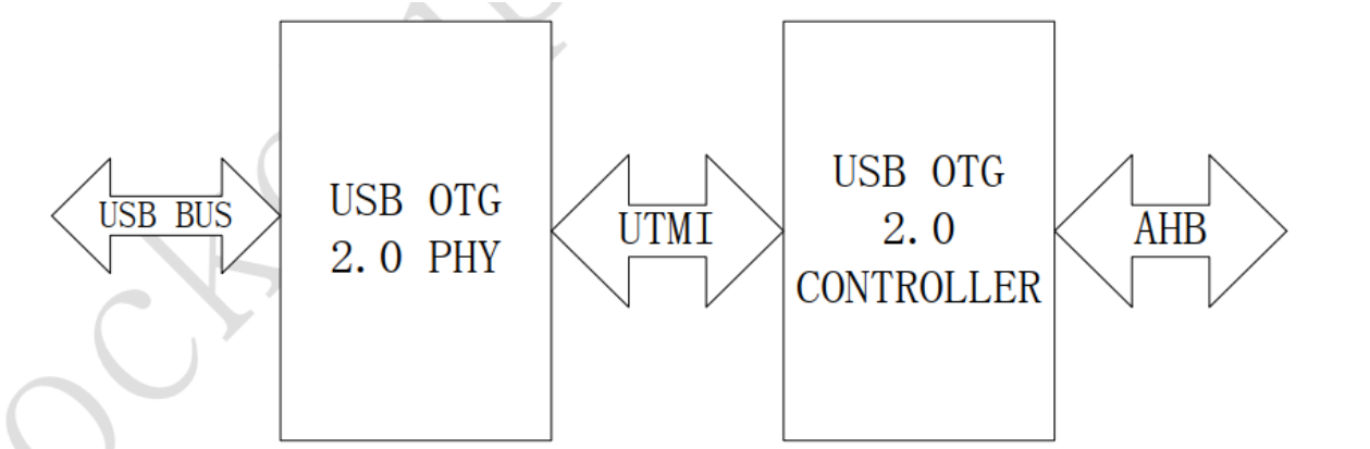
Figure 1-2 USB 2.0 OTG Block Diagram
1.4 USB 3.0 OTG
Compatible Specification Universal Serial Bus 3.0 Specification, Revision 1.0 Universal Serial Bus Specification, Revision 2.0 eXtensible Host Controller Interface for Universal Serial Bus(xHCI), Revision 1.1 DWC3 Features Support Control/Bulk(including stream)/Interrupt/IsochronousTransfer Simultaneous IN and OUT transfer for USB 3.0, up to 8Gbps bandwidth Descriptor Caching and Data Pre-fetching USB 3.0 Device Features Up to 7 IN endpoints, including control endpoint 0 Up to 6 OUT endpoints, including control endpoint 0 Up to 13 endpoint transfer resources, each one for each endpoint Flexible endpoint configuration for multiple applications/USBset-configuration modes Hardware handles ERDY and burst Stream-based bulk endpoints with controller automatically initiatingdata movement Isochronous endpoints with isochronous data in data buffers Flexible Descriptor with rich set of features to support bufferinterrupt moderation, multiple transfers, isochronous, control, and scatteredbuffering support USB 3.0 Dual-Role Device(DRD) Features Static Device operation Static Host operation USB 3.0/USB 2.0 OTG A device and B device basing on ID UFP/DFP and Data Role Swap Defined in USB TypeC Specification Not support USB 3.0/USB 2.0 OTG session request protocol(SRP), hostnegotiation protocol(HNP) and
Role Swap Protocol(RSP) USB 3.0 xHCI Host Features Support up to 64 devices Support 1 interrupter Support 1 USB 2.0 port and 1 Super-Speed port Concurrent USB 3.0/USB 2.0 traffic, up to 8.48Gbps bandwidth Support standard or open-source xHCI and class driver Support xHCI Debug Capability
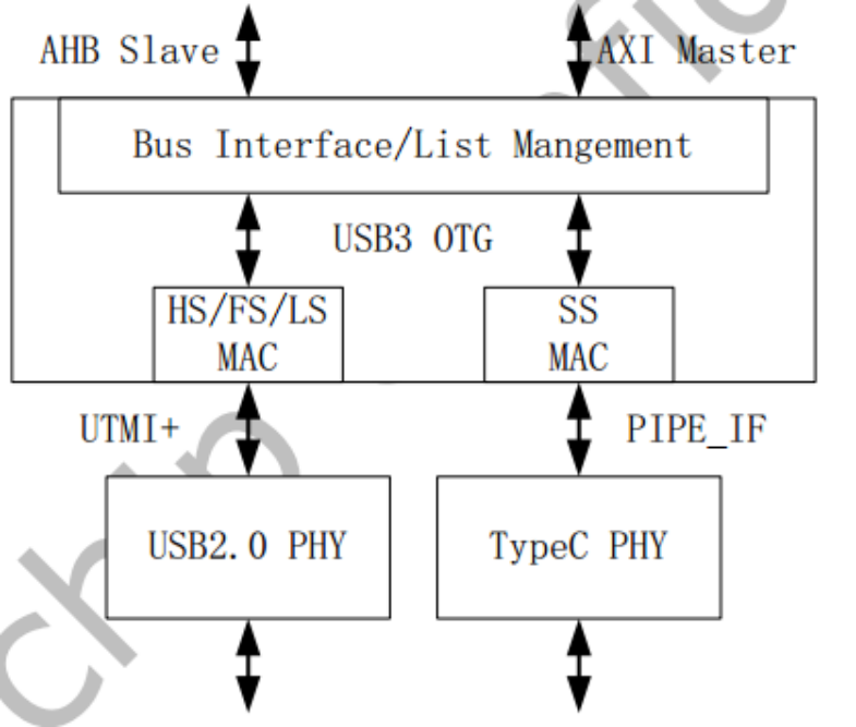
Figure 1-3 USB 3.0 OTG Block Diagram
1.5 USB 2.0 PHY
The USB 2.0 PHY supports two designs, one port and two ports. Figure 1-4 below is a block diagram that supports two ports.
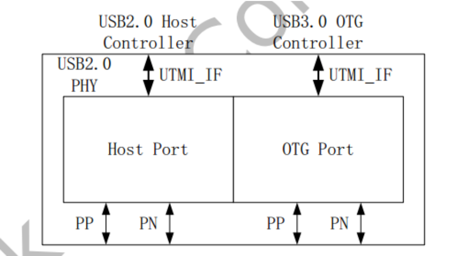
Figure 1-4 USB 2.0 PHY Block Diagram Host Port: connect to USB 2.0 Host controller via UTMI+ OTG Port: connect to USB 3.0 OTG controller or USB 2.0 logic module of USB 2.0 OTG controller via UTMI+
1.6 Type-C USB 3.0 PHY
Support USB 3.0 (SuperSpeed only) Support DisplayPort 1.3 (RBR, HBR and HBR2 data rates only) Support DisplayPort AUX channel Support USB TypeC and DisplayPort Alt Mode Support DisplayPort Alt Mode on TypeC A, B, C, D, E and F pinassignments Support Normal and Flipped orientation
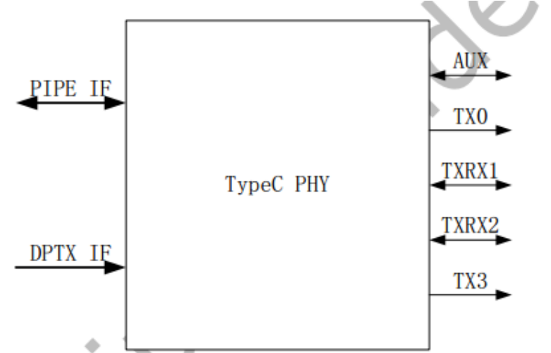
Figure 1-5 TypeC PHY Block Diagram
2. Hardware Circuits and Signals
2.1 USB 2.0 Host Hardware Circuits
This chapter introduces the hardware circuit design and signal of USB 2.0 HOST. According to the type of USB
2.0 PHY used, it can be divided into common USB 2.0 HOST hardware circuit and USB 2.0 HSIC hardware circuit.
2.1.1 USB 2.0 Host Common Hardware Circuit
USB 2.0 works at 480MHz clock, it is suggested that the width of USB 2.0 DP/DM lines should be 7-8 MIL and 90 Ω impedance differential. It is better to layout on the surface layer and cover the ground, and no interference source on the edge and no other signal line on the right upper and lower layers. Example (USB 2.0 HOST hardware circuit design of RK3399 SoC). The SoC pins of the USB 2.0 Host controller are shown in Figure 2-1
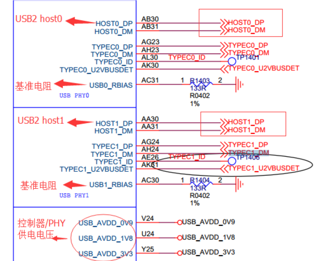
Figure 2-1 USB 2.0 HOST pin in SoC The control circuit and interface circuit of USB 2.0 Host VBUS are shown in Figure 2-2 and Figure 2-3
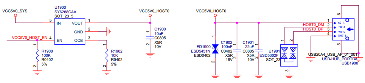
Figure 2-2 USB 2.0 Host VBUS control circuit and interface circuit

Figure 2-3 USB 2.0 Host VBUS GPIO controller pin
2.1.2 USB 2.0 HSIC Hardware Circuit
HSIC (High Speed Inter Chip) uses 240 MHz DDR signal, so the transmission rate is 480 Mbps, the same as USB 2.0, and the typical line impedance is 50 Ω. It is suggested that the maximum length of the line should not exceed 10 cm on the PCB. As shown in Figure 2-4, USIC_STROBE is 240MHz DDR signal line, USIC_DATA is data line. The power supply voltage is only 0.9V and 1.2V, and standard voltage of signal transmission is 1.2V, which has lower power consumption than USB 2.0 PHY. Example (USB 2.0 HSIC hardware circuit design of RK3399 SoC)
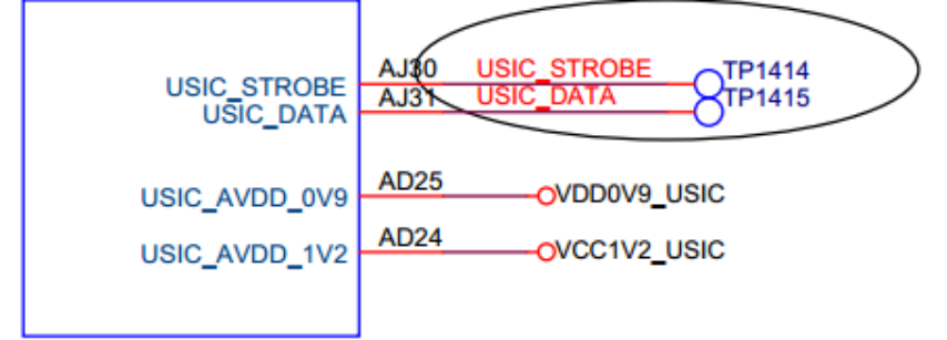
Figure 2-4 USB 2.0 HSIC pin in SoC
2.2 USB OTG Hardware Circuits
2.2.1 USB 2.0 OTG Hardware Circuit
USB 2.0 OTG related hardware signals: OTG_DP/OTG_DM: USB differential signal D+/D-, need to place 2.2Ω series resistance on each signal line. USB_DET: Input signal, used for OTG Peripheral mode to determine whether to connect to Host or USB charger. Default is low level 0V. If connect to Host or USB charger, the high level is 3.0~3.2 V.
USB_ID: Input signal, used to determine whether to switch to Host mode or Peripheral mode. Default is high level 1.8V (pull-up inside chip), and OTG works as Peripheral mode. The USB_ID will be pull-down to the ground if connect with OTG-Host cable, and the USB driver will swith OTG to Host mode if the USB_ID level changes from high to low voltage. USB_RBIAS: Base resistance of USB 2.0 PHY. Because the resistance of the resistor will affect the amplitude of the USB signal, so please strictly follow the resistance design of the SDK reference schematic diagram. VCC5V0_OTG: When OTG work as Peripheral mode, it’s the input origin signal of USB_DET. When OTG work as Host mode, it’s supply VBUS 5V for USB Devices. USB_AVDD_1V0/USB_AVDD_1V8/USB_AVDD_3V3: Power supply for USB 2.0 PHY. USB 2.0 OTG PHY power supply: USB_AVDD_1V0, USB_AVDD_1V8, USB_AVDD_3V3 The complete USB 2.0 OTG reference circuit is shown in Figures 2-5 ~ 2-8 (Reference to PX30 EVB).
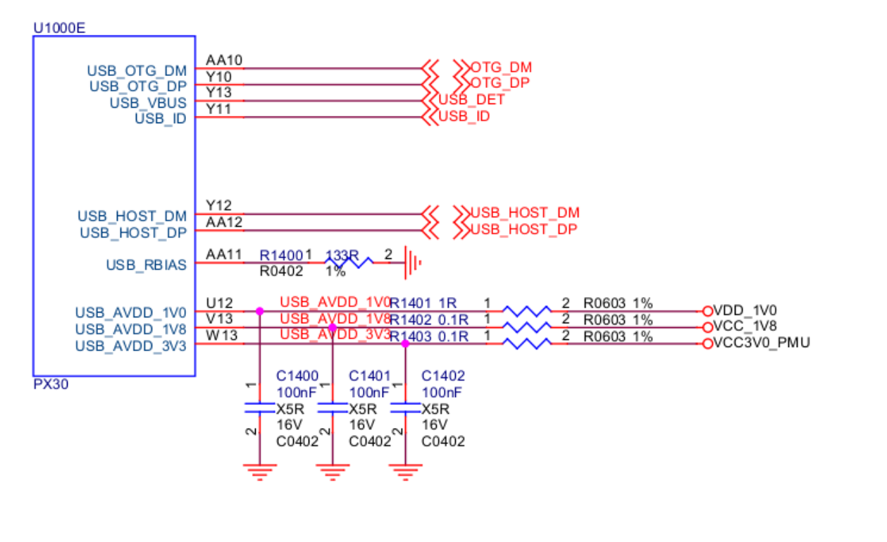
Figure 2-5 USB 2.0 OTG pin in SoC
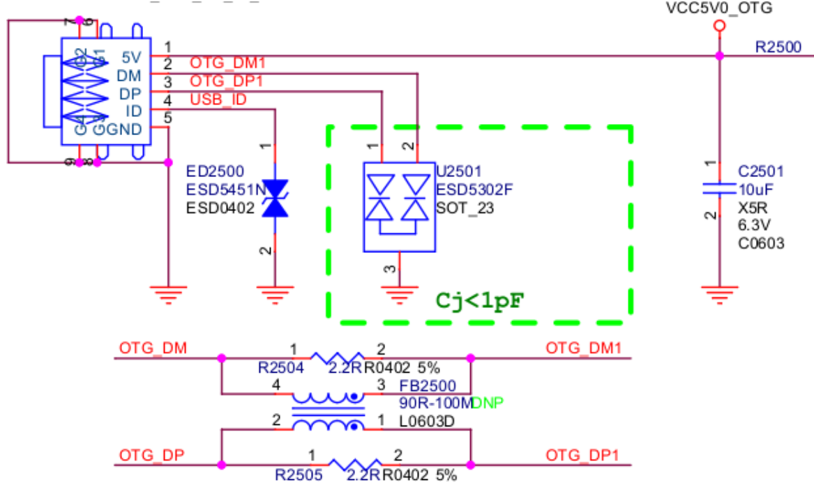
Figure 2-6 USB 2.0 OTG Micro-Interface
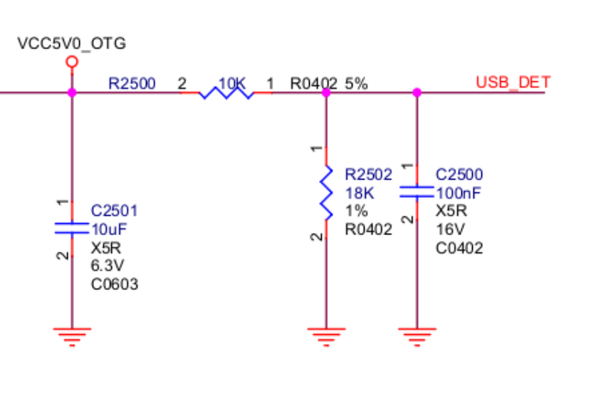
Figure 2-7 USB 2.0 OTG_DET circuit
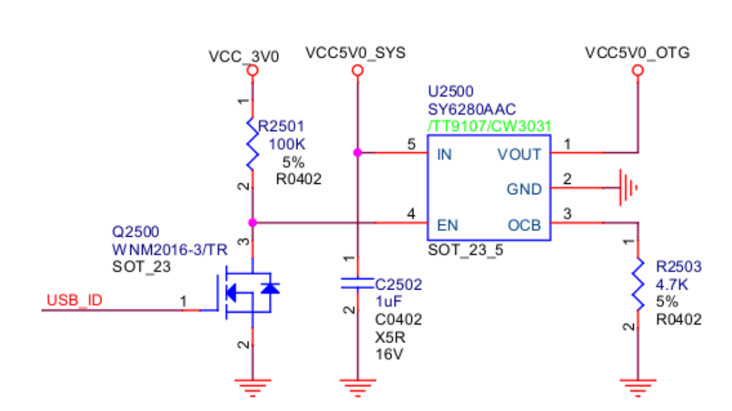
Figure 2-8 USB 2.0 OTG_DRV circuit
2.2.2 USB 3.0 OTG Hardware Circuit
The maximum transmission rate of USB 3.0 OTG is 5Gbps, which is downward compatible with USB 2.0 OTG function. The physical interface is Type-C or Type-A. The USB 3.0 OTG supports 4-wire differential signal lines up to 3 meters and 11-inch PCB. In order to avoid interference and reduce electromagnetic interference, the 5Gbps signal is transmitted by differential signal on long cable. Figure 2-9 ~ 2-14 is the Type-C USB 3.0 related circuit design of RK3399 platform.

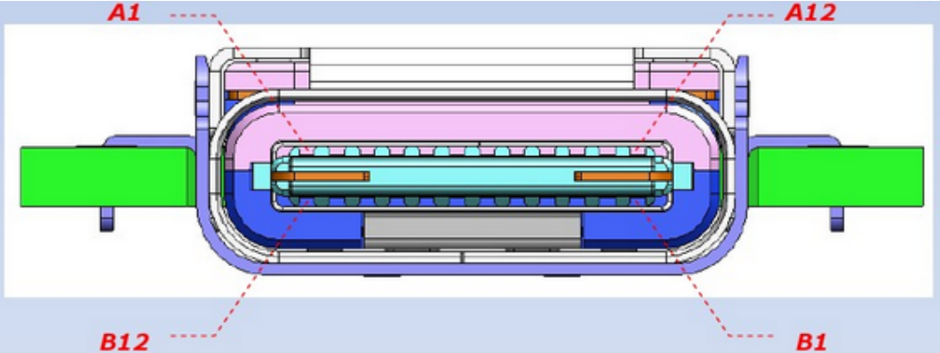
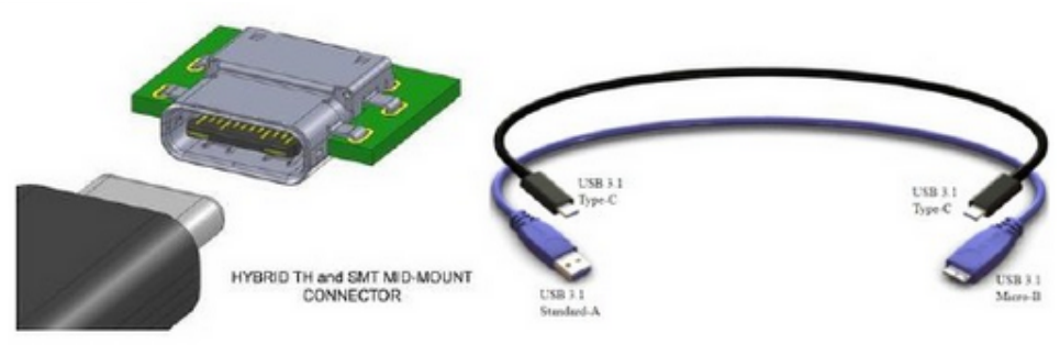
Figure 2-9 Type-C interface definition
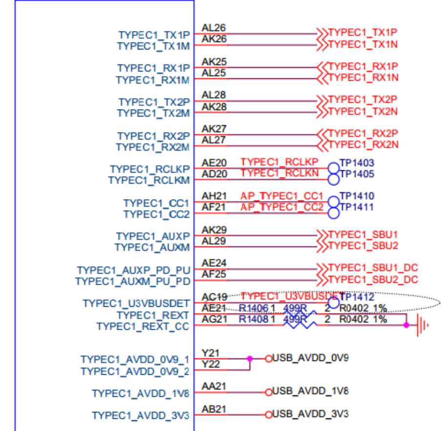
Figure 2-10 USB 3.0 OTG pin in SoC
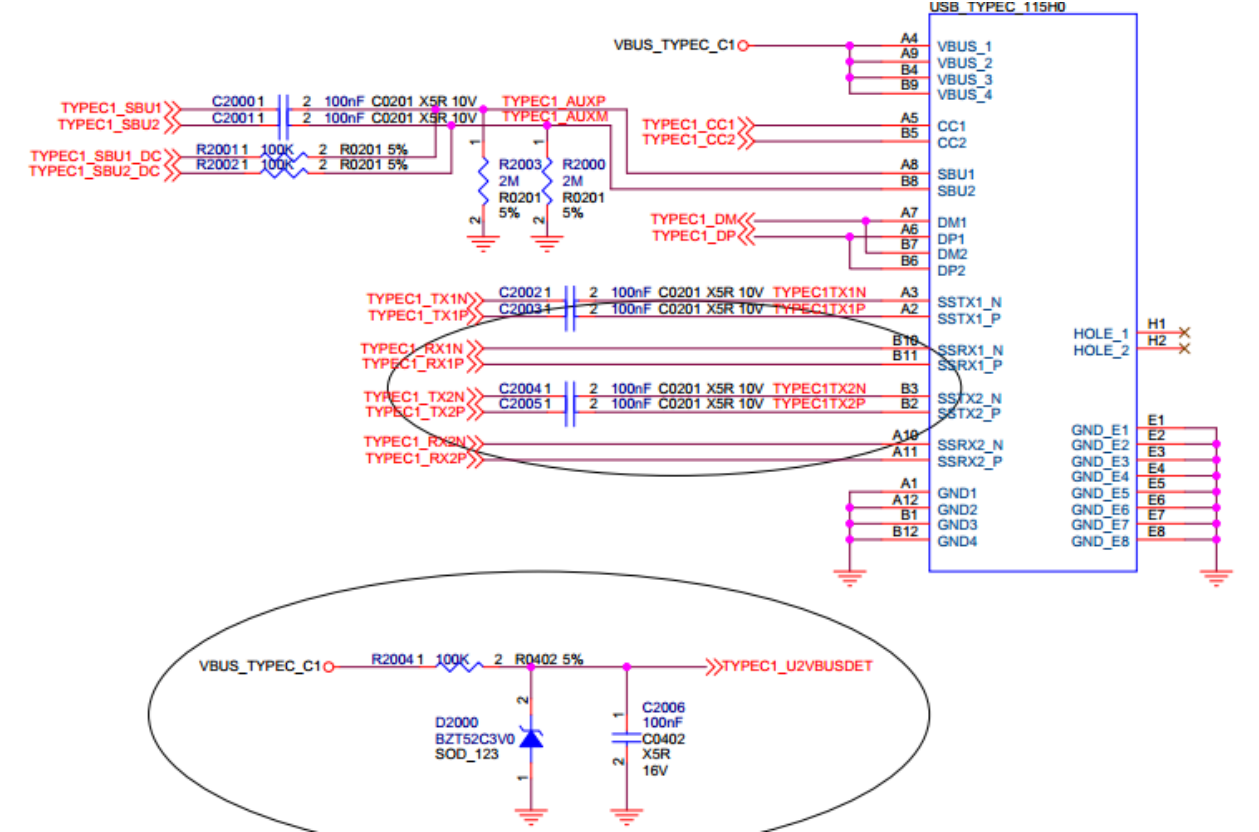
Figure 2-11 USB 3.0 OTG Type-C interface
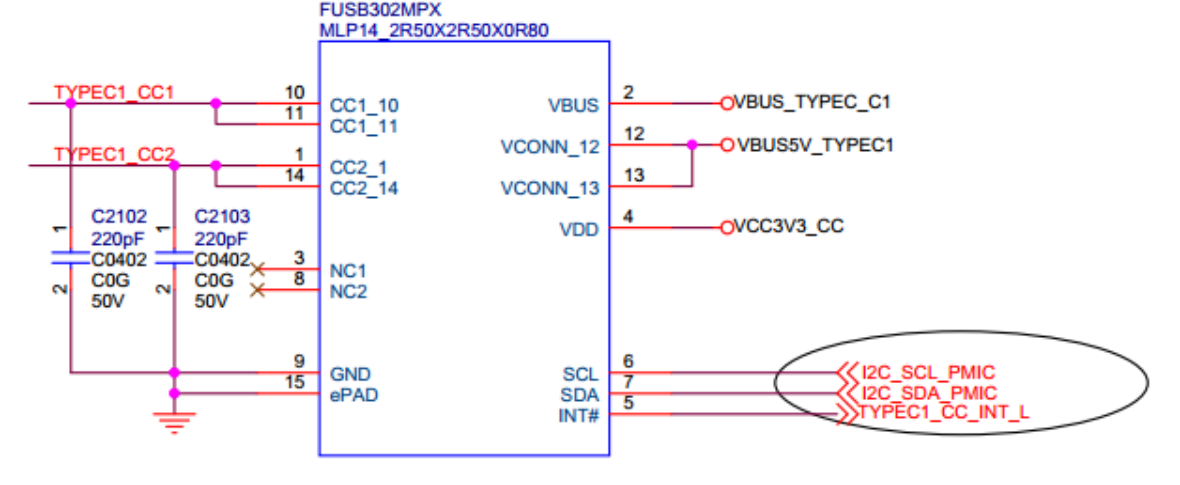
Figure 2-12 USB 3.0 Type-C CC detection circuit (FUSB302)
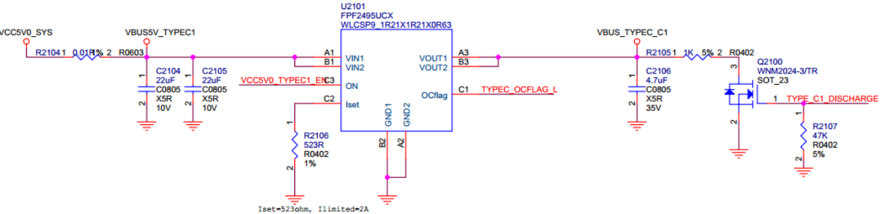

Figure 2-13 USB 3.0 VBUS Control Circuit-1 (Control by GPIO)
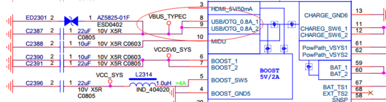
Figure 2-14 USB 3.0 VBUS Control-2 (Control by RK818)
2.3 USB GPIO Hardware Circuit
USB GPIO usage scenarios include: VBUS Regulator GPIO: Used for VBUS voltage control in Host mode, to output or turn off 5V; VBUSDET GPIO: Used for hot-plug detection in Device mode, to detect the USB VBUS voltage level, controlling USB charging detection logic and USB PHY dynamic power consumption management strategies; OTG_ID GPIO: Used for dynamic switching between Device/Host modes, typically used for Micro/Mini USB2.0 physical interfaces. If using a Type-C physical interface, a CC to ID conversion circuit is required. Since VBUS Regulator GPIO is a common usage method on the Rockchip platform, this section only describes the hardware circuit design for VBUSDET and OTG_ID GPIOs. For chips where the VBUSDET and OTG_ID PINs are not packaged (e.g., RK3506G), if support for Device hot-plug and automatic switching between Device/Host modes based on the USB physical interface ID voltage level changes is required, GPIO detection of USB VBUS and ID voltage level changes is necessary.
2.3.1 USB VBUSDET GPIO Hardware Circuit Design
VBUSDET GPIO is used for hot-plug detection in Device mode, similar to the common USB PHY VBUSDET. For chips where the USB PHY VBUSDET PIN is not packaged (e.g., RK3506G), VBUSDET GPIO can be considered to detect changes in the voltage level of VBUS at the USB physical interface, controlling USB charging detection logic and USB PHY dynamic power consumption management strategies. Specific use case assessment for VBUSDET GPIO: For chips where the USB PHY VBUSDET PIN is not packaged, VBUSDET GPIO is not mandatory, as the Device mode connection initiation behavior does not depend on VBUSDET GPIO; Scenarios requiring VBUSDET GPIO:
- OTG in Device mode, requiring USB charging detection functionality or dynamic management of USB PHY suspend/normal mode to reduce operational power consumption;
- OTG in Device mode, requiring detection of USB disconnection behavior; Scenarios not requiring VBUSDET GPIO:
- Chips where the USB PHY’s VBUSDET PIN is packaged (e.g., RK3506B), no additional VBUSDET
GPIO is needed;
- OTG only in Host mode, no Device mode requirement (except for firmware burning), no VBUSDET GPIO is needed;
- OTG in Device mode, but without the need for USB charging detection functionality and without dynamic management of USB PHY power consumption (i.e., allowing the system to operate with USB2 PHY always in Normal mode), VBUSDET GPIO can be omitted. However, this also results in the inability to detect USB disconnection behavior. If detection of USB disconnection behavior is needed, manual modification of the USB controller driver is required, based on the USB controller’s suspend interrupt to determine USB Disconnect. Taking the RK3506G_EVB1 hardware design schematic as an example, the VBUSDET GPIO circuit design is shown in Figure 2-15. Points to note in the circuit design: A transistor is added between the USB interface input VBUS and VBUSDET GPIO, inverting the input VBUS voltage level; When the USB interface input VBUS is at a high level, the corresponding GPIO is at a low level; When the USB interface input VBUS is at a low level, the corresponding GPIO is at a high level. Note: The purpose of inverting the input VBUS voltage level is: For self-powered USB devices, it can prevent leakage current from the Host’s VBUS to the chip side when the device is not powered on, thus avoiding potential issues when the USB device is connected to the Host.
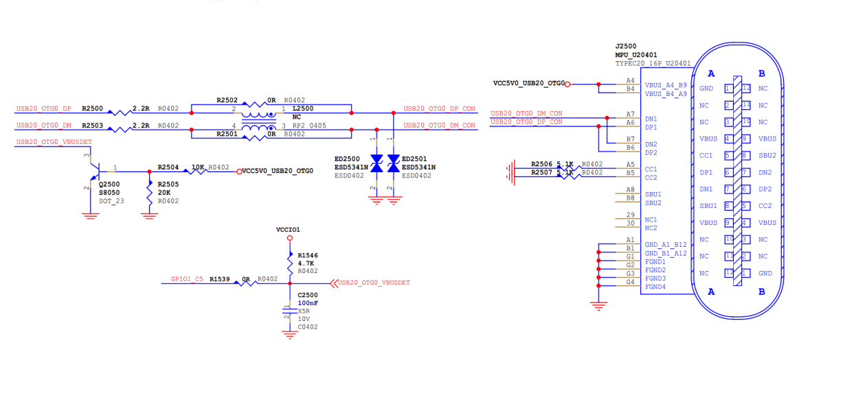
Figure 2-15 USB VBUSDET GPIO Hardware Circuit Diagram
2.3.2 USB OTG_ID GPIO Hardware Circuit Design
The OTG_ID GPIO is used to implement automatic switching between Device/Host modes and is typically used in conjunction with Micro/Mini USB2.0 physical interfaces. If a Type-C physical interface is used, a CC to ID conversion circuit is required. Specific use case assessment for OTG_ID GPIO:
For chips where the USB PHY’s ID PIN is not packaged, ID GPIO is not mandatory because the switching between Device/Host modes can also be achieved through the OTG switch commands described in USB Common Commands. Scenarios that should consider ID GPIO: There is a need for OTG to switch between Device/Host modes and a requirement for the mode to automatically switch based on the inserted USB cable. Scenarios that do not require the use of ID GPIO:
- Chips where the USB PHY’s ID PIN is packaged (e.g., RK3506B) do not require an additional ID GPIO.
- Although OTG has a need for switching between Device/Host modes, it is permissible to implement dynamic switching between Device/Host modes through software switch commands. Taking the RK3506G Test1 hardware design schematic as an example, the OTG_ID GPIO circuit design is shown in Figure 2-16. Points to note in the circuit design: No pull-up circuit design is required externally for ID. The ID design of the USB standard cable is as follows: The ID of the USB Device cable is left floating; the ID of the USB Host (OTG) cable is short-circuited to GND, i.e., ID is pulled low, indicating that OTG should operate in Host mode. To be compatible with such standard cables, the circuit design for USB OTG_ID to GPIO requires ID GPIO to default to a weak pull-up, corresponding to Device mode. When an OTG adapter cable is inserted, ID is pulled low, switching to Host mode.
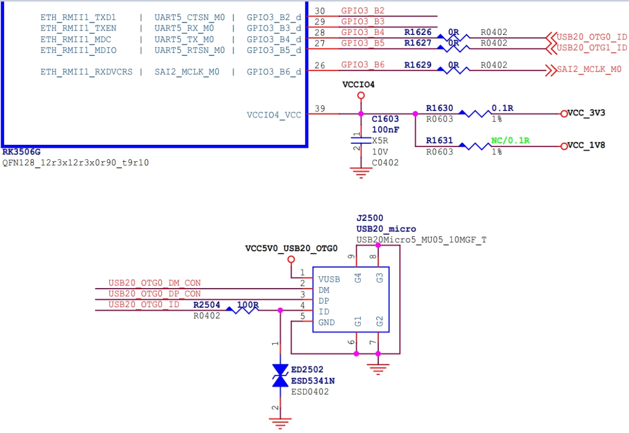
Figure 2-16 USB OTG_ID GPIO Hardware Circuit Diagram
3. Kernel USB CONFIG
The configuration and saving of the USB module is the same as the other kernel modules. Import the default configuration:
make ARCH=arm64 rockchip_defconfig
Select kernel configuration:
make ARCH=arm64 menuconfig
Save the configuration:
make ARCH=arm64 savedefconfig
Use the defconfig instead of the rockchip_defconfig
3.1 USB PHY CONFIG
Device Drivers  --->
    PHY Subsystem  --->
        ...
        <*> Rockchip INNO USB2PHY Driver
        ...
        <*> Rockchip TYPEC PHY Driver
        ...
        <*> Rockchip INNO USB 3.0 PHY Driver
“Rockchip INNO USB2PHY Driver” is used for USB 2.0 PHY with Innosilicon IP block; “Rockchip TYPEC PHY Driver” is used for USB 3.0 PHY IP block, e.g. RK3399; “Rockchip INNO USB 3.0 PHY Driver” is used for USB 3.0 PHY with Innosilicon IP block, e.g. RK3328;
3.2 USB Host CONFIG
The configuration of the USB Host module is located at
Device Drivers  --->
        [*] USB support  --->
-*- Support for Host-side USB
...
<*> xHCI HCD (USB 3.0) support
-*- Generic xHCI driver for a platform device
...
<*> EHCI HCD (USB 2.0) support
[ ]     Root Hub Transaction Translators
[*]     Improved Transaction Translator scheduling
<*> Generic EHCI driver for a platform device
...
<*> OHCI HCD (USB 1.1) support
< >     OHCI support for PCI-bus USB controllers
<*>     Generic OHCI driver for a platform device
Select the “USB support” first to add core support for USB. Select the “Supportfor Host-side USB” to add core support for USB HOST. Select the OHCI configurations to support USB 1.1 HOST. Select the EHCI configurations to support USB 2.0 HOST. Select the xHCI configurations to support USB 3.0 HOST. Note: In order to cut the Kernel core, the rk3308_linux_defconfig used for RK3308 doesn’t support USB HOST. But actually, RK3308 SoC integrates one USB 2.0 Host controller (EHCI&OHCI). Select the OHCI/EHCI configurations and the related device class drivers if you want to use USB 2.0 HOST interface on RK3308 Board.
3.3 USB OTG CONFIG
Select the “DesignWare USB2 DRD Core Support” and the mode for USB 2.0 OTG controller driver. Select the “DesignWare USB3 DRD Core Support“ and the mode for USB 3.0 OTG Controller driver.
Device Drivers  --->
    -*- Support for Host-side USB
    [*] USB support  --->
        ...
        <*> DesignWare USB2 DRD Core Support
                DWC2 Mode Selection (Dual Role mode)
        ...
        <*> DesignWare USB3 DRD Core Support
                DWC3 Mode Selection (Dual Role mode)
3.4 USB Gadget CONFIG
Rockchip platforms support the USB Gadget ACM, RNDIS, MSC, MTP, PTP, Accessory, ADB, MIDI, Audio function by default. Developers can enable more USB Gadget functions according to actual product requirements, but at the same time, init files in Android system need to be modified. (init.rk30board.usb.rc and init.usb.configfs.rc).
DeviceDrivers  --->
    [*]USB support  --->
        [*] USB Gadget Support  --->
            ...
            USBGadget Drivers (USB functions configurable through configfs)  --->
                [ ]       Generic serial bulk in/out
                [*]       Abstract Control Model (CDC ACM)
                [ ]       Object Exchange Model (CDC OBEX)
                [ ]       Network Control Model (CDC NCM)
                [ ]       Ethernet Control Model (CDC ECM)
                [ ]       Ethernet Control Model (CDC ECM) subset
                [*]       RNDIS
                [ ]       Ethernet Emulation Model (EEM)
                [*]       Mass storage
                [ ]       Loopback and sourcesink function (for testing)
                [*]       Function filesystem (FunctionFS)
                [*]       MTP gadget
                [*]         PTP gadget
                [*]       Accessory gadget
                [*]         Audio Source gadget
                [*]       Uevent notification of Gadget state
                [ ]       Audio Class 1.0
                [ ]       Audio Class 2.0
                [*]       MIDI function
                [ ]       HID function
                [ ]       USB Webcam function
                [ ]       Printer function
3.5 USB Device Class Driver CONFIG
3.5.1 Mass Storage Class CONFIG
The U disk belongs to SCSI device, so the SCSI options need to be configured before enable the USB Mass Storage configuration.
Device Drivers --->
    SCSI device support --->
        <*> SCSI device support
[ ] SCSI: use blk-mq I/O path by default
[*] legacy /proc/scsi/ support
    *** SCSI support type (disk, tape, CD-ROM) ***
<*> SCSI disk support
< > SCSI tape support
< > SCSI OnStream SC-x0 tape support
< > SCSI CDROM support
<*> SCSI generic support
<*> SCSI media changer support
[*] Verbose SCSI error reporting (kernel size +=75K)
[*] SCSI logging facility
[*] Asynchronous SCSI scanning
    SCSI Transports  --->
[*] SCSI low-level drivers  --->
[ ] PCMCIA SCSI adapter support  ----
[ ] SCSI Device Handlers  ----
After add SCSI Device Support, you can enable the “USB Mass Storage support” in “USB Support”.
Device Driver --->
    [*] USB support  --->
        <*> USB Mass Storage support
3.5.2 USB Serial Converter CONFIG
Support USB 3G Modem
Device Driver --->
    [*] USB support  --->
        <*> USB Serial Converter support  --->
            <*>   USB driver for GSM and CDMA modems
Device Driver --->
    [*] Network device support  --->
        <*>   PPP (point-to-point protocol) support
            <*>     PPP BSD-Compress compression
            <*>     PPP Deflate compression
            [*]     PPP filtering
            <*>     PPP MPPE compression (encryption)
            [*]     PPP multilink support
            <*>     PPP over Ethernet
            <*>     PPP over L2TP
            <*>     PPP on L2TP Access Concentrator
            <*>     PPP on PPTP Network Server
<*>     PPP support for async serial ports
<*>     PPP support for sync tty ports
Support PL2303 Select the following configuration for PL203, and disable the “USB driver for GSM and CDMA modems” configuration at the same time. Otherwise, PL2303 may be misidentified as USB 3G modem.
Device Driver --->
    [*] USB support  --->
        <*> USB Serial Converter support  --->
            <*> USB Prolific 2303 Single Port Serial Driver
Support USB GPS (e.g. u-blox 6 - GPS Receiver)
Device Drivers  --->
    [*] USB support --->
        [*] USB Modem (CDC ACM) support
3.5.3 USB HID CONFIG
Select the following HID configuration to support generic USB Mouse and Keyboard.
Device Drivers  --->
    [*] HID support
        [*] USB HID transport layer
        [ ] PID device support
        [*] /dev/hiddev raw HID device support
3.5.4 USB Net CONFIG
USB Bluetooth CONFIG
[*] Networking support  --->
    ...
    <*> Bluetooth subsystem support  --->
        Bluetooth device drivers  --->
            ...
            <*> HCI USB driver
            [*]   Broadcom protocol support (NEW)
            [*]   Realtek protocol support (NEW)
            ...
USB WIFI CONFIG Need to add WIFI Vendor special driver. USB Ethernet CONFIG
Device Driver --->
    [*] Network device support  --->
        <*> USB Network Adapters  --->
            <*> USB CATC NetMate-based Ethernet device support
            <*> USB KLSI KL5USB101-based ethernet device support
            <*> USB Pegasus/Pegasus-II based ethernet device support
            <*> USB RTL8150 based ethernet device support
            <*> Realtek RTL8152/RTL8153 Based USB Ethernet Adapters
            < > Microchip LAN78XX Based USB Ethernet Adapters
            <*> Multi-purpose USB Networking Framework
            <*>     ASIX AX88xxx Based USB 2.0 Ethernet Adapters
            <*>     ASIX AX88179/178A USB 3.0/2.0 to Gigabit Ethernet
            -*- CDC Ethernet support (smart devices such as cable modems)
            <*> CDC EEM support
            -*- CDC NCM support
            < > Huawei NCM embedded AT channel support
            <*> CDC MBIM support
            <*> Davicom DM96xx based USB 10/100 ethernet devices
            < > CoreChip-sz SR9700 based USB 1.1 10/100 ethernet devices
            < > CoreChip-sz SR9800 based USB 2.0 10/100 ethernet devices
            <*> SMSC LAN75XX based USB 2.0 gigabit ethernet devices
            <*> SMSC LAN95XX based USB 2.0 10/100 ethernet devices
            <*> GeneSys GL620USB-A based cables
            <*> NetChip 1080 based cables (Laplink, ...)
            <*> Prolific PL-2301/2302/25A1/27A1 based cables
            <*> MosChip MCS7830 based Ethernet adapters
            <*> Host for RNDIS and ActiveSync devices
            <*> Simple USB Network Links (CDC Ethernet subset)
            [*]     ALi M5632 based 'USB 2.0 Data Link' cables
            [*]     AnchorChips 2720 based cables (Xircom PGUNET, ...)
            [*]     eTEK based host-to-host cables (Advance, Belkin, ...)
            [*]     Embedded ARM Linux links (iPaq, ...)
            [*]     Epson 2888 based firmware (DEVELOPMENT)
            [*]     KT Technology KC2190 based cables (InstaNet)
<*> Sharp Zaurus (stock ROMs) and compatible
<*> Conexant CX82310 USB ethernet port
<*> Samsung Kalmia based LTE USB modem
<*> QMI WWAN driver for Qualcomm MSM based 3G and LTE modems
<*> Option USB High Speed Mobile Devices
<*> Intellon PLC based usb adapter
<*> Apple iPhone USB Ethernet driver
<*> USB-to-WWAN Driver for Sierra Wireless modems
< > LG VL600 modem dongle
< > QingHeng CH9200 USB ethernet support
3.5.5 USB Camera CONFIG
Device Driver --->
    <*> Multimedia support  --->
        [*]   Media USB Adapters  --->
            *** Webcam devices ***
            <*> USB Video Class (UVC)
            [*] UVC input events device support
3.5.6 USB Audio CONFIG
Device Driver --->
    <*> Sound card support  --->
        <*> Advanced Linux Sound Architecture --->
            ...
            [*] USB sound devices   --->
                [*] USB Audio /MIDI driver
3.5.7 USB HUB CONFIG
Disable the configuration “Disable external HUBs” to support the external USB HUB.
Device Drivers --->
    [*] USB support --->
        -*- Support for Host-side USB
        ...
        [ ]     Disable external hubs
There are many other USB devices that may be used, such as GPS, Printer, etc. It may need Vendor customized driver or standard Class driver. If you need to support these USB devices, you can search methods via internet to support them. Rockchip platforms have no special requirements, you can directly refer to those methods.
4. USB DTS Configuration
4.1 USB 2.0/3.0 PHY DTS
USB PHY is divided into USB 2.0 PHY and USB 3.0 PHY. These two PHYs are independent of each other, and their characteristics are quite different, so you need to configure DTS separately. Note: The USB PHY DTS configuration of the RK3399 SoC is more flexible and complicated, please refer to the document: Rockchip_RK3399_Developer_Guide_USB_DTS_CN
4.1.1 USB 2.0 PHY DTS
Rockchip series SoCs mainly use two USB 2.0 PHY IPs: Innosilicon IP and Synopsis IP. The hardware design of these two IPs is different, so the corresponding PHY DTS configuration is also different. Most of the Rockchip series USB 2.0 PHYs use Innosilicon IP.
- USB 2.0 PHY DTS Configuration Document Innosilicon USB 2.0 PHY DTS configuration document (for SoCs other than RK3188/RK3288) Documentation/devicetree/bindings/phy/phy-rockchip-inno-usb2.txt Synopsis USB 2.0 PHY DTS Configuration document (for RK3188/RK3288 SoC) Documentation/devicetree/bindings/phy/rockchip-usb-phy.txt
- USB 2.0 PHY DTS Example Example (RK3399 USB 2.0 PHY0 DTS) USB 2.0 PHY parent node: RK3399 USB 2.0 PHY registers are in GRF, so use GRF node as the parent of USB 2.0 PHY, and use the base address of GRF. USB 2.0 PHY node: RK3399 USB 2.0 PHY is a combphy, it comprises with a Host port and a OTG port. And both of these two port use the same reference input clock and the same 480MHz out clock. And also use the same address offset of GRF for USB PHY configuration. USB 2.0 PHY sub-nodes: A sub-node is required for each port the phy provides. The sub-node name is used to identify Host or OTG port, “otg-port” is the name of otg port, “host-port” is the name of host port. These two port has different interrupts.
grf: syscon@ff770000 {
    compatible = "rockchip,rk3399-grf", "syscon", "simple-mfd";
    reg = <0x0 0xff770000 0x0 0x10000>;
    #address-cells = <1>;
    #size-cells = <1>;
    u2phy0: usb2-phy@e450 {
        compatible = "rockchip,rk3399-usb2phy";
        reg = <0xe450 0x10>;
        clocks = <&cru SCLK_USB2PHY0_REF>;
        clock-names = "phyclk";
        #clock-cells = <0>;
        clock-output-names = "clk_usbphy0_480m";
        status = "disabled";

        u2phy0_host: host-port {
            #phy-cells = <0>;
            interrupts = <GIC_SPI 27 IRQ_TYPE_LEVEL_HIGH 0>;
            interrupt-names = "linestate";
            status = "disabled";
        };

        u2phy0_otg: otg-port {
            #phy-cells = <0>;
            interrupts = <GIC_SPI 103 IRQ_TYPE_LEVEL_HIGH 0>,
                         <GIC_SPI 104 IRQ_TYPE_LEVEL_HIGH 0>,
                         <GIC_SPI 106 IRQ_TYPE_LEVEL_HIGH 0>;
            interrupt-names = "otg-bvalid", "otg-id",
                              "linestate";
            status = "disabled";
        };
    };
};
For Host port and OTG port host mode, we may need to config regulator for USB VBUS 5V in board DTS, it’s an optional property. Example (RK3399 USB 2.0 Host VBUS regulator property in DTS) The control method of RK3399 USB 2.0 Host VBUS is: if GPIO is pulled high, the VBUS 5V output is enabled; when GPIO is pulled low, the VBUS 5V output is closed. In DTS, regulator is used to configure GPIO. Among them, the attribute “regulator-always-on” indicates that after the system is started, the GPIO is pulled up to enable the VBUS 5V output until the system is shut down.
vcc5v0_host: vcc5v0-host-regulator {
    compatible = "regulator-fixed";
    enable-active-high;
    gpio = <&gpio4 25 GPIO_ACTIVE_HIGH>;
    pinctrl-names = "default";
    pinctrl-0 = <&host_vbus_drv>;
    regulator-name = "vcc5v0_host";
    regulator-always-on;
};

usb2 {
    host_vbus_drv: host-vbus-drv {
        rockchip,pins =
                <4 25 RK_FUNC_GPIO &pcfg_pull_none>;
    };
};
Set the “phy-supply” property to the regulator “vcc5v0_host“ that provides power to VBUS 5V. In this way, the core code of the PHY framework will automatically parse the attribute and control the GPIO corresponding to the USB VBUS.
u2phy0_host: host-port {
    phy-supply = <&vcc5v0_host>;
    status = "okay";
};
4.1.2 USB 3.0 PHY DTS
Rockchip series SoCs mainly use three types of USB 3.0 PHY IP: Type-C PHY IP, Innosilicon USB 3.0 PHY IP and Innosilicon USB 3.0 CombPhy IP. These three IPs have different hardware designs, so their corresponding PHY DTS configurations are also different.
- USB 3.0 PHY DTS Configuration Document Type-C PHY DTS configuration document(for RK3399/RK3399Pro SoC) Documentation/devicetree/bindings/phy/phy-rockchip-typec.txt Innosilicon USB 3.0 PHY DTS configuration document(for RK3228H/RK3228 Soc) Documentation/devicetree/bindings/phy/phy-rockchip-inno-usb3.txt Innosilicon USB 3.0 Combphy configuration document(for RK1808 SoC, USB 3.0 & PCIe Combphy) Documentation/devicetree/bindings/phy/phy-rockchip-inno-combophy.txt
- USB 3.0 PHY DTS Example Example (RK3399 Type-C0 USB 3.0 PHY) Type-C PHY is a combination of USB 3.0 SuperSpeed PHY and DisplayPort Transmit PHY. So the tcphy0 has two sub-nodes “tcphy0_dp” and “tcphy0_usb3”. main DTS attribute description: rockchip,grf : phandle to the syscon managing the “general register files” . rockchip,typec-conn-dir : the register of type-c connector direction. rockchip,usb3tousb2-en : the register of type-c force usb3 to usb2 enable. rockchip,external-psm : the register of type-c phy external psm clock. rockchip,pipe-status : the register of type-c phy pipe status. rockchip,uphy-dp-sel : the register of type-c phy selection for DP.
tcphy0: phy@ff7c0000 {
    compatible = "rockchip,rk3399-typec-phy";
    reg = <0x0 0xff7c0000 0x0 0x40000>;
    rockchip,grf = <&grf>;
    #phy-cells = <1>;
    clocks = <&cru SCLK_UPHY0_TCPDCORE>,
             <&cru SCLK_UPHY0_TCPDPHY_REF>;
    clock-names = "tcpdcore", "tcpdphy-ref";
    assigned-clocks = <&cru SCLK_UPHY0_TCPDCORE>;
    assigned-clock-rates = <50000000>;
    power-domains = <&power RK3399_PD_TCPD0>;
    resets = <&cru SRST_UPHY0>,
             <&cru SRST_UPHY0_PIPE_L00>,
             <&cru SRST_P_UPHY0_TCPHY>;
    reset-names = "uphy", "uphy-pipe", "uphy-tcphy";
    rockchip,typec-conn-dir = <0xe580 0 16>;
    rockchip,usb3tousb2-en = <0xe580 3 19>;
    rockchip,usb3-host-disable = <0x2434 0 16>;
    rockchip,usb3-host-port = <0x2434 12 28>;
    rockchip,external-psm = <0xe588 14 30>;
    rockchip,pipe-status = <0xe5c0 0 0>;
    rockchip,uphy-dp-sel = <0x6268 19 19>;
    status = "disabled";

    tcphy0_dp: dp-port {
        #phy-cells = <0>;
    };

    tcphy0_usb3: usb3-port {
        #phy-cells = <0>;
    };
};
Note: There are 2 type-c phys for RK3399, and they are almost identical. This document only describes the configuration of RK3399 USB 3.0 Type-C PHY in DTSI. In fact, there are some related configurations in DTS such as the extcon attribute and the hardware attributes of CC chip (FUSB302). For details, please refer to the document: “Rockchip_RK3399_Developer_Guide_USB_CN”
4.2 USB 2.0 Controller DTS
There are two different architectures controllers: EHCI (Enhanced Host Controller Interfac, only support USB 2.0) and OHCI (Open Host Controller Interface, support USB 1.1 & 1.0) DWC2 (DesignWare Cores USB 2.0 Hi-Speed On-The-Go (OTG), support USB 2.0 & 1.1 & & 1.0)
The following describes the two different architectures of the USB 2.0 controller DTS.
4.2.1 USB 2.0 Host Controller DTS
- USB 2.0 Host Controller DTS configuration document Documentation/devicetree/bindings/usb/usb-ehci.txt Documentation/devicetree/bindings/usb/usb-ohci.txt
- USB 2.0 Host Controller DTS example Example (DTS of RK3399 USB 2.0 Host0 EHCI & OHCI Controller) The compatible of the EHCI controller is fixed as “generic-ehci”, and the compatible of the OHCI controller is fixed as “generic-ohci”. In addition, EHCI and OHCI multiplex the same clocks and phys. Attribute “power-domains” needs to be configured only when the SoC’s USB 2.0 Host controller supports the power-domains function.
usb_host0_ehci: usb@fe380000 {
    compatible = "generic-ehci";
    reg = <0x0 0xfe380000 0x0 0x20000>;
    interrupts = <GIC_SPI 26 IRQ_TYPE_LEVEL_HIGH 0>;
    clocks = <&cru HCLK_HOST0>, <&cru HCLK_HOST0_ARB>,
             <&cru SCLK_USBPHY0_480M_SRC>;
    clock-names = "hclk_host0", "hclk_host0_arb", "usbphy0_480m";
    phys = <&u2phy0_host>;
    phy-names = "usb";
    power-domains = <&power RK3399_PD_PERIHP>;
    status = "disabled";
};

usb_host0_ohci: usb@fe3a0000 {
    compatible = "generic-ohci";
    reg = <0x0 0xfe3a0000 0x0 0x20000>;
    interrupts = <GIC_SPI 28 IRQ_TYPE_LEVEL_HIGH 0>;
    clocks = <&cru HCLK_HOST0>, <&cru HCLK_HOST0_ARB>,
             <&cru SCLK_USBPHY0_480M_SRC>;
    clock-names = "hclk_host0", "hclk_host0_arb", "usbphy0_480m";
    phys = <&u2phy0_host>;
    phy-names = "usb";
    power-domains = <&power RK3399_PD_PERIHP>;
    status = "disabled";
};
4.2.2 USB 2.0 OTG Controller DTS
- USB 2.0 OTG Controller DTS configuration document The USB 2.0 OTG uses a DWC2 controller. In the Linux-4.4 kernel, the DWC2 controller driver has two versions (dwc2 driver and dwc_otg_310 driver). Among them, the dwc_otg_310 driver is an older version of the driver only used for RK3288/RK3368 SoC. In the Linux-4.19 kernel, DWC2 controller use the dwc2 driver version for all SoCs and is no longer compatible with the old dwc_otg_310 driver. DTS configuration file for dwc2 driver (for Linux-4.4 and newer kernels) Documentation/devicetree/bindings/usb/dwc2.txt Documentation/devicetree/bindings/usb/generic.txt DTS configuration document for dwc_otg_310 driver (only for Linux-4.4, RK3288/RK3368 SoC) Documentation/devicetree/bindings/usb/rockchip-usb.txt
- USB 2.0 OTG Controller example Example (DTS of RK3328 USB 2.0 OTG) Main attribute as follows: dr_mode: shall be one of “host”, “peripheral” and “otg” ( Refer to usb/generic.txt). g-rx-fifo-size: size of rx fifo size in gadget mode. g-np-tx-fifo-size: size of non-periodic tx fifo size in gadget mode. g-tx-fifo-size: size of tx fifo per endpoint (except ep0) in gadget mode. g-use-dma: enable dma usage in gadget driver. phys: phy provider specifier. phy-names: shall be “usb2-phy”. Among them, “g-np-tx-fifo-size”, “g-rx-fifo-size” and “g-tx-fifo-size” are used for fifo configuration in device mode, which can be configured accroding to the actual USB device application of the product. The requirements are described as follows:
- “g-np-tx-fifo-size” configure the endpoint 0 fifo of the device. It is recommended to fix it to 16 (unit: 4Bytes);
- “g-rx-fifo-size” configure the receiving fifo of the device OUT Endpoint. All OUT Endpoints share one receiving fifo. It is recommended to fix it to 275 (unit: 4Bytes);
- “g-tx-fifo-size” configure the sending fifo of the device IN Endpoint, each IN Endpoint has a dedicated sending fifo. The corresponding tx-fifo can be configured according to the number of IN Endpoints actually used. When configuring tx-fifo, there are two principles:
- tx-fifo cannot be smaller than EP max-packet;
- The larger the tx-fifo, the better the transmission performance, so if the tx-fifo is large enough, it is recommended to configure it to be 2 times or larger than the EP max-packet;
usb20_otg: usb@ff580000 {
    compatible = "rockchip,rk3328-usb", "rockchip,rk3066-usb",
                 "snps,dwc2";
    reg = <0x0 0xff580000 0x0 0x40000>;
    interrupts = <GIC_SPI 23 IRQ_TYPE_LEVEL_HIGH>;
    clocks = <&cru HCLK_OTG>, <&cru HCLK_OTG_PMU>;
    clock-names = "otg", "otg_pmu";
    dr_mode = "otg";
    g-np-tx-fifo-size = <16>;
    g-rx-fifo-size = <275>;
    g-tx-fifo-size = <256 128 128 64 64 32>;
    g-use-dma;
    phys = <&u2phy_otg>;
    phy-names = "usb2-phy";
    status = "disabled";
};
4.3 USB 3.0 Controller DTS
4.3.1 USB 3.0 Host Controller DTS
USB 3.0 Host controller is xHCI, integrated in DWC3 OTG IP, so it is not necessary to configure DTS separately for xHCI. We only need to configure DWC3 DTS, and set the “dr_mode” attribute of DWC3 to “otg” or “host”.
4.3.2 USB 3.0 OTG Controller DTS
- USB 3.0 OTG Controller DTS Configuration Document The USB 3.0 OTG uses a DWC3 controller. Linux-4.4 and Linux-4.19 or later kernel versions have different USB
3.0 OTG DTS configurations because Linux-4.19 USB DWC3 controller driver has been upgraded significantly compared to Linux-4.4 (for specific differences, please refer to USB 3.0 OTG Driver) Linux-4.4 USB 3.0 OTG controller DTS configuration document Documentation/devicetree/bindings/usb/dwc3.txt (DWC3 Controller common attribute configuration description) Documentation/devicetree/bindings/usb/generic.txt (USB Controller common attribute configuration description) Documentation/devicetree/bindings/usb/rockchip,dwc3.txt (for RK3399/RK1808 SoC) Documentation/devicetree/bindings/usb/rockchip-inno,dwc3.txt (for RK3328/RK3228H SoC) Linux-4.19 and newer kernel USB 3.0 OTG Controller DTS configuration document Documentation/devicetree/bindings/usb/dwc3.txt (DWC3 Controller common attribute configuration description) Documentation/devicetree/bindings/usb/generic.txt (USB Controller common attribute configuration description)
Documentation/devicetree/bindings/usb/rockchip-inno,dwc3.txt (for RK3328/RK3228H SoC) Differences in DTS configuration between Linux-4.4 and 4.19 USB 3.0 controllers DWC3’s power-domains, restets and extcon attribute have different reference locations. In Linux-4.4 kernel, these three attributes are placed on the parent node (usbdrd3) of the DWC3 controller, while in Linux-4.19 kernel, these three attributes are moved to the child nodes (usbdrd_dwc3) of the DWC3 controller; When configuring Type-C to Type-A USB 2.0/3.0 OTG DTS, it is necessary to add the configuration of the extcon attribute in the USB controller sub-node (usbdrd_dwc3) to support software switching OTG mode in Linux-4.19 kernel, but not in Linux-4.4 kernel.
- USB 3.0 OTG Controller DTS Example Example (RK3399 USB 3.0 OTG DTS in Linux-4.4 kernel) The USB 3.0 OTG DTS includes a parent node “usbdrd3_0” and a child node “usbdrd_dwc3_0”. For all SoCs except for RK3328/RK3228H supporting DWC3 controller, compatible attribute in the parent node must add “rockchip, rk3399-dwc3”. The child nodes of all SoCs are configured as “snps, dwc3”. The role of the parent node is to configure chip-level related attributes, such as clocks, power-domains, and reset. The role of the child node is to configure the controller-related attributes in which the quirk attribute is applicable to the DWC3 controllers of all SoCs.
usbdrd3_0: usb0 {
        compatible = "rockchip,rk3399-dwc3";
        clocks = <&cru SCLK_USB3OTG0_REF>, <&cru SCLK_USB3OTG0_SUSPEND>,
             <&cru ACLK_USB3OTG0>, <&cru ACLK_USB3_GRF>;
        clock-names = "ref_clk", "suspend_clk",
                  "bus_clk", "grf_clk";
        power-domains = <&power RK3399_PD_USB3>;
        resets = <&cru SRST_A_USB3_OTG0>;
        reset-names = "usb3-otg";
        #address-cells = <2>;
        #size-cells = <2>;
        ranges;
        status = "disabled";

        usbdrd_dwc3_0: dwc3@fe800000 {
            compatible = "snps,dwc3";
            reg = <0x0 0xfe800000 0x0 0x100000>;
            interrupts = <GIC_SPI 105 IRQ_TYPE_LEVEL_HIGH 0>;
            dr_mode = "otg";
            phys = <&u2phy0_otg>, <&tcphy0_usb3>;
            phy-names = "usb2-phy", "usb3-phy";
            phy_type = "utmi_wide";
            snps,dis_enblslpm_quirk;
            snps,dis-u2-freeclk-exists-quirk;
            snps,dis_u2_susphy_quirk;
            snps,dis-del-phy-power-chg-quirk;
            snps,tx-ipgap-linecheck-dis-quirk;
            snps,xhci-slow-suspend-quirk;
            snps,xhci-trb-ent-quirk;
            snps,usb3-warm-reset-on-resume-quirk;
        status = "disabled";
    };
};
4.4 USB GPIO DTS
Starting from Linux-6.1, the Rockchip SDK supports USB VBUSDET/GPIO functionality, using the driver drivers/extcon/extcon-usb-gpio.c . This driver manages the initialization and interrupt handling of VBUSDET/GPIO interrupts and sends notifications to the USB PHY driver through the extcon message management mechanism. Subsequently, in the USB PHY driver, based on the status of EXTCON_USB/EXTCON_USB_HOST, it completes the hot-plug detection for USB Device and OTG mode switching. For detailed software processing procedures, please refer to the relevant section USB GPIO Driver and Software Processing Flow.
4.4.1 USB VBUSDET GPIO DTS
Taking the RK3506G EVB1 design as an example, based on the USB VBUSDET GPIO Hardware Circuit Design, the VBUSDET GPIO corresponds to GPIO1_C5, and the DTS reference configuration is as follows:
extcon_usb: extcon-usb {
        compatible = "linux,extcon-usb-gpio";
        /* The hardware design inverts the voltage level, so it must be configured as
GPIO_ACTIVE_LOW here. */
        vbus-gpio = <&gpio1 RK_PC5 GPIO_ACTIVE_LOW>;
        pinctrl-names = "default";
        pinctrl-0 = <&usb_extcon_vbus>;
        status = "okay";
};

&pinctrl {
        usb {
                usb_extcon_vbus: usb-extcon-vbus {
                rockchip,pins = <1 RK_PC5 RK_FUNC_GPIO &pcfg_pull_none>;
            };
        };
};

&u2phy_otg0 {
        /* Add the property rockchip,gpio-vbus-det, indicating that the PHY driver supports
VBUS GPIO detection method. */
        rockchip,gpio-vbus-det;
        status = "okay";
};

&usb2phy {
        extcon = <&extcon_usb>;
        status = "okay";
};
Note: For USB PHY VBUSDET PIN that are not packaged and hardware designs that do not support VBUSDET GPIO circuitry, the aforementioned VBUSDET GPIO DTS configuration is not required. However, it is necessary to add the attribute “rockchip,vbus-always-on” in the u2phy_otg0 node, indicating the deactivation of the charging detection function and the dynamic suspend entry function of the USB2 PHY OTG0 port.
&u2phy_otg0 {
        rockchip,vbus-always-on;
};
4.4.2 USB OTG_ID GPIO DTS
Taking the RK3506G TEST1 design as an example, based on the USB OTG_ID GPIO Hardware Circuit Design, the ID GPIO corresponds to GPIO3_B4, and the DTS reference configuration is as follows:
extcon_usb: extcon-usb {
        compatible = "linux,extcon-usb-gpio";
        id-gpio = <&gpio3 RK_PB4 GPIO_ACTIVE_HIGH>;
        /* Must set pinctrl-names to "default", otherwise the pcfg_pull_up configuration
will not take effect. */
        pinctrl-names = "default";
        pinctrl-0 = <&usb_extcon_id>;
        status = "okay";
};

&pinctrl {
        usb {
                usb_extcon_id: usb-extcon-id {
                        /* The ID should be internally pulled high by default, so it should
be configured as pcfg_pull_up. */
                        rockchip,pins = <3 RK_PB4 RK_FUNC_GPIO &pcfg_pull_up>;
                };
        };
};

&u2phy_otg0 {
        /* Add the property rockchip,gpio-id-det, indicating that the PHY driver supports ID
GPIO detection method. */
        rockchip,gpio-id-det;
        status = "okay";
};

&usb2phy {
        extcon = <&extcon_usb>;
        status = "okay";
};
4.4.3 USB VBUSDET/OTG_ID GPIO DTS
For chips where neither the ID PIN nor the USB_VBUSDET PIN are packaged (such as RK3506G), if the hardware needs to support both GPIO VBUS detection and GPIO ID detection, the corresponding DTS reference configuration based on the RK3506G TEST1 reference design is as follows:
extcon_usb: extcon-usb {
        compatible = "linux,extcon-usb-gpio";
        vbus-gpio = <&gpio3 RK_PB2 GPIO_ACTIVE_LOW>;
        id-gpio = <&gpio3 RK_PB4 GPIO_ACTIVE_HIGH>;
        /* Must set pinctrl-names to "default", otherwise the pcfg_pull_up configuration
will not take effect. */
        pinctrl-names = "default";
        /* pinctrl-0 references both usb_extcon_vbus and usb_extcon_id simultaneously. */
        pinctrl-0 = <&usb_extcon_vbus &usb_extcon_id>;
        status = "okay";
};

&pinctrl {
        usb {
                usb_extcon_id: usb-extcon-id {
                        rockchip,pins = <3 RK_PB4 RK_FUNC_GPIO &pcfg_pull_up>;
                };

                usb_extcon_vbus: usb-extcon-vbus {
                        rockchip,pins = <3 RK_PB2 RK_FUNC_GPIO &pcfg_pull_none>;
                };
        };
};

&u2phy_otg0 {
        rockchip,gpio-vbus-det;
        rockchip,gpio-id-det;
        status = "okay";
};

&usb2phy {
        extcon = <&extcon_usb>;
        status = "okay";
};
5. USB Driver Development
5.1 Linux USB Driver Framework
The Linux USB protocol stack is a layered architecture, as shown in Figure 5-1 below. The left is the USB device driver, the right is the USB host driver, and the bottom layer is the driver for the different USB controllers and PHYs of the Rockchip SoCs.
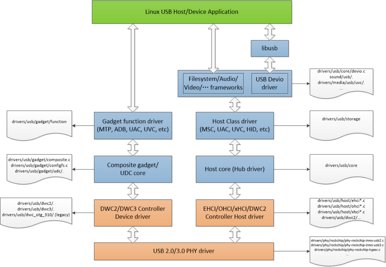
Figure 5-1 Linux USB driver framework
5.2 USB PHY Drivers
This chapter mainly introduces the driver code of PHY briefly. If you want to know more about the hardware framework, register description, signal adjustment of PHY, please refer to the chip TRM and the USB SQ Tool documentation “Rockchip_Introduction_USB_SQ_Tool_CN”.
5.2.1 USB 2.0 PHY Driver
Rockchip SoCs mainly use two USB 2.0 PHY IPs: Innosilicon IP and Synopsis IP. The hardware design of these two IPs is different, so a separate USB PHY driver is required. At the same time, SoCs with the same USB 2.0 PHY IP use the same driver, instead of each SoC having a dedicated driver.
- USB 2.0 PHT driver code Innosilicon USB 2.0 PHY Driver code drivers/phy/phy-rockchip-inno-usb2.c Synopsis USB 2.0 PHY Driver code (only used for RK3188/RK3288): drivers/phy/rockchip/phy-rockchip-usb.c For the time being, most of SoCs except RK3188/RK3288 use Innosilicon IP, so this chapter mainly introduces Innosilicon IP.
- Innosilicon USB 2.0 PHY IP feature Fully compliant with USB specification Rev 2.0 Support 480Mbps/12Mbps/1.5Mbps serial data transmission Support all test modes defined in USB2.0 Specification Support one port of one PHY, or two ports of one PHY (Comprises with one OTG port and one Host port) OTG Port support dual-role device fully support Battery Charge 1.2 Specification
- USB 2.0 PHY driver’s important structure In the USB 2.0 PHY driver, there is an important structure rockchip_usb2phy_cfg, which is mainly used to operate the USB PHY related registers. When adding a new SoC support for Innosilicon USB 2.0 PHY, the main job is to add the corresponding rkxxxx_phy_cfgs structure.
struct rockchip_usb2phy_cfg {
        unsigned int    reg;
        unsigned int    num_ports;
        int (*phy_tuning)(struct rockchip_usb2phy *);
        struct usb2phy_reg      clkout_ctl;
        const struct rockchip_usb2phy_port_cfg  port_cfgs[USB2PHY_NUM_PORTS];
        const struct rockchip_chg_det_reg       chg_det;
};
The members of the rockchip_usb2phy_cfg structure are described as follows: reg: the offset address of the USB PHY in the GRF module. This address should be the same as the corresponding reg attrbute of the DTS USB 2.0 PHY. The purpose is to match the configuration of the DTS PHY and the PHY in the driver. num_ports: defines the number of ports supported by the USB PHY. For example, if OTG port and Host port are supported, num_ports is 2. phy_tuning: used for USB PHY signal adjustment, such as increasing pre-emphasis and increasing signal amplitude. clkout_ctl: controls the USB PHY’s 480MHz output clock. port_cfgs: register configuration of USB PHY port. chg_det: register configuration related to charge detection.
- USB 2.0 PHY state machine The USB 2.0 PHY driver has three works that are used to handle different state machines: rockchip_chg_detect_work: charge detection function for OTG port device mode; rockchip_usb2phy_otg_sm_work: detect the connection status of the OTG port and control the PHY to enter/exit suspend; rockchip_usb2phy_sm_work: detect the connection status of the host port and control the PHY to enter/exit suspend; In the driver, dev_dbg log has been added in key places, which makes it easy to view the state machine rotation during device connection and disconnection.
- USB 2.0 PHY Driver Development Example Example (RK3399 USB 3.0 PHY driver) RK3399 supports two independent USB 2.0 PHYs. Each PHY comprises with one OTG port and one Host port. OTG port is used for USB3.0 OTG controller with Type-C USB 3.0 PHY to comprise as fully feature Type-C. Host port is used for USB2.0 host controller. The detailed rk3399_phy_cfgs structure code is as follows: The registers in port_cfgs is mainly used for PHY suspend mode control, VBUS level status detection, OTG ID level status detection, DP/DM line level status detection, etc. For the specific function description of each member, please refer to the notes of the structure members in the driver.
static const struct rockchip_usb2phy_cfg rk3399_phy_cfgs[] = {
        {
                .reg            = 0xe450,
                .num_ports      = 2,
                .phy_tuning     = rk3399_usb2phy_tuning,
                .clkout_ctl     = { 0xe450, 4, 4, 1, 0 },
                .port_cfgs      = {
                        [USB2PHY_PORT_OTG] = {
                                .phy_sus = { 0xe454, 8, 0, 0x052, 0x1d1 },
                                .bvalid_det_en  = { 0xe3c0, 3, 3, 0, 1 },
                                .bvalid_det_st  = { 0xe3e0, 3, 3, 0, 1 },
                                .bvalid_det_clr = { 0xe3d0, 3, 3, 0, 1 },
                                .bypass_dm_en   = { 0xe450, 2, 2, 0, 1 },
                                .bypass_sel     = { 0xe450, 3, 3, 0, 1 },
                                .idfall_det_en  = { 0xe3c0, 5, 5, 0, 1 },
                                .idfall_det_st  = { 0xe3e0, 5, 5, 0, 1 },
                                .idfall_det_clr = { 0xe3d0, 5, 5, 0, 1 },
                                .idrise_det_en  = { 0xe3c0, 4, 4, 0, 1 },
                                .idrise_det_st  = { 0xe3e0, 4, 4, 0, 1 },
                                .idrise_det_clr = { 0xe3d0, 4, 4, 0, 1 },
                                .ls_det_en      = { 0xe3c0, 2, 2, 0, 1 },
                                .ls_det_st      = { 0xe3e0, 2, 2, 0, 1 },
                                .ls_det_clr     = { 0xe3d0, 2, 2, 0, 1 },
                                .utmi_avalid    = { 0xe2ac, 7, 7, 0, 1 },
                                .utmi_bvalid    = { 0xe2ac, 12, 12, 0, 1 },
                                .utmi_iddig     = { 0xe2ac, 8, 8, 0, 1 },
                                .utmi_ls        = { 0xe2ac, 14, 13, 0, 1 },
                                .vbus_det_en    = { 0x449c, 15, 15, 1, 0 },
                },
                [USB2PHY_PORT_HOST] = {
                        .phy_sus        = { 0xe458, 1, 0, 0x2, 0x1 },
                        .ls_det_en      = { 0xe3c0, 6, 6, 0, 1 },
                        .ls_det_st      = { 0xe3e0, 6, 6, 0, 1 },
                        .ls_det_clr     = { 0xe3d0, 6, 6, 0, 1 },
                        .utmi_ls        = { 0xe2ac, 22, 21, 0, 1 },
                        .utmi_hstdet    = { 0xe2ac, 23, 23, 0, 1 }
                }
        },
        .chg_det = {
                .opmode         = { 0xe454, 3, 0, 5, 1 },
                .cp_det         = { 0xe2ac, 2, 2, 0, 1 },
                .dcp_det        = { 0xe2ac, 1, 1, 0, 1 },
                .dp_det         = { 0xe2ac, 0, 0, 0, 1 },
                .idm_sink_en    = { 0xe450, 8, 8, 0, 1 },
                .idp_sink_en    = { 0xe450, 7, 7, 0, 1 },
                .idp_src_en     = { 0xe450, 9, 9, 0, 1 },
                .rdm_pdwn_en    = { 0xe450, 10, 10, 0, 1 },
                .vdm_src_en     = { 0xe450, 12, 12, 0, 1 },
                .vdp_src_en     = { 0xe450, 11, 11, 0, 1 },
        },
},
{
        .reg            = 0xe460,
        .num_ports      = 2,
        .phy_tuning     = rk3399_usb2phy_tuning,
        .clkout_ctl     = { 0xe460, 4, 4, 1, 0 },
        .port_cfgs      = {
                [USB2PHY_PORT_OTG] = {
                        .phy_sus = { 0xe464, 8, 0, 0x052, 0x1d1 },
                        .bvalid_det_en  = { 0xe3c0, 8, 8, 0, 1 },
                        .bvalid_det_st  = { 0xe3e0, 8, 8, 0, 1 },
                        .bvalid_det_clr = { 0xe3d0, 8, 8, 0, 1 },
                        .idfall_det_en  = { 0xe3c0, 10, 10, 0, 1 },
                        .idfall_det_st  = { 0xe3e0, 10, 10, 0, 1 },
                        .idfall_det_clr = { 0xe3d0, 10, 10, 0, 1 },
                        .idrise_det_en  = { 0xe3c0, 9, 9, 0, 1 },
                        .idrise_det_st  = { 0xe3e0, 9, 9, 0, 1 },
                        .idrise_det_clr = { 0xe3d0, 9, 9, 0, 1 },
                        .ls_det_en      = { 0xe3c0, 7, 7, 0, 1 },
                        .ls_det_st      = { 0xe3e0, 7, 7, 0, 1 },
                        .ls_det_clr     = { 0xe3d0, 7, 7, 0, 1 },
                        .utmi_avalid    = { 0xe2ac, 10, 10, 0, 1 },
                        .utmi_bvalid    = { 0xe2ac, 16, 16, 0, 1 },
                        .utmi_iddig     = { 0xe2ac, 11, 11, 0, 1 },
                        .utmi_ls        = { 0xe2ac, 18, 17, 0, 1 },
                        .vbus_det_en    = { 0x451c, 15, 15, 1, 0 },
                },
                [USB2PHY_PORT_HOST] = {
                        .phy_sus        = { 0xe468, 1, 0, 0x2, 0x1 },
                        .ls_det_en      = { 0xe3c0, 11, 11, 0, 1 },
                        .ls_det_st      = { 0xe3e0, 11, 11, 0, 1 },
                                .ls_det_clr     = { 0xe3d0, 11, 11, 0, 1 },
                                .utmi_ls        = { 0xe2ac, 26, 25, 0, 1 },
                                .utmi_hstdet    = { 0xe2ac, 27, 27, 0, 1 }
                        }
                },
                .chg_det = {
                        .opmode         = { 0xe464, 3, 0, 5, 1 },
                        .cp_det         = { 0xe2ac, 5, 5, 0, 1 },
                        .dcp_det        = { 0xe2ac, 4, 4, 0, 1 },
                        .dp_det         = { 0xe2ac, 3, 3, 0, 1 },
                        .idm_sink_en    = { 0xe460, 8, 8, 0, 1 },
                        .idp_sink_en    = { 0xe460, 7, 7, 0, 1 },
                        .idp_src_en     = { 0xe460, 9, 9, 0, 1 },
                        .rdm_pdwn_en    = { 0xe460, 10, 10, 0, 1 },
                        .vdm_src_en     = { 0xe460, 12, 12, 0, 1 },
                        .vdp_src_en     = { 0xe460, 11, 11, 0, 1 },
                },
        },
        { /* sentinel */ }
};
- USB 2.0 PHY Debug Interface
/sys/devices/platform/[u2phy dev name] # ls
driver          extcon   of_node  phy   subsystem
driver_override modalias otg_mode power uevent
The “otg_mode” node is used to switch the OTG Device/Host mode by software, and it is not affected by the OTG ID level status. For example: Force host mode echo host > /sys/devices/platform/[u2phy dev name]/otg_mode Force device mode echo peripheral > /sys/devices/platform/[u2phy dev name]/otg_mode Force otg mode echo otg > /sys/devices/platform/[u2phy dev name]/otg_mode At the same time, the node is still compatible with the old order of Linux-3.10 and earlier, namely: Force host mode echo 1 > /sys/devices/platform/[u2phy dev name]/otg_mode Force device mode echo 2 > /sys/devices/platform/[u2phy dev name]/otg_mode Force otg mode echo 0 > /sys/devices/platform/[u2phy dev name]/otg_mode
Note:
- [U2phy dev name] in the USB 2.0 PHY full path needs to be modified to the specific PHY node name corresponding to the SoC.
- RV1126/RV1109 USB OTG needs additional operations for force mode. RV1126/RV1109 USB OTG force Host mode echo disconnect > /sys/class/udc/ffd00000.dwc3/soft_connect (disconnect usb device) echo host > /sys/devices/platform/ff4c0000.usb2-phy/otg_mode RV1126/RV1109 USB OTG force Device mode echo peripheral > /sys/devices/platform/ff4c0000.usb2-phy/otg_mode echo connect > /sys/class/udc/ffd00000.dwc3/soft_connect (connect usb device) RV1126/RV1109 USB OTG force OTG mode echo otg > /sys/devices/platform/ff4c0000.usb2-phy/otg_mode echo connect > /sys/class/udc/ffd00000.dwc3/soft_connect (connect usb device)
5.2.2 USB 3.0 PHY Drivers
Rockchip SoCs mainly use three types of USB 3.0 PHY IP: Type-C PHY IP, Innosilicon USB 3.0 PHY IP and Innosilicon USB 3.0 CombPhy IP. These three IPs have different hardware designs, so they need separate USB PHY drivers. Note that all three USB 3.0 PHY IPs only support SuperSpeed, so they must be used together with USB 2.0 PHY to fully support the USB 3.0 protocol(supporting HighSpeed/FullSpeed/LowSpeed). The three different USB 3.0 PHY IP drivers are briefly described below.
- Type-C PHY Driver Type-C USB 3.0 PHY driver code drivers/phy/rockchip/phy-rockchip-typec.c Type-C USB 3.0 PHY driver example Example (RK3399 Type-C PHY) Type-C PHY is a combination of USB 3.0 SuperSpeed PHY and DisplayPort Transmit PHY. Please refer to Type-C USB 3.0 PHY to learn about Type-C PHY’s features. In the probe function of Type-C PHY driver, rockchip_dp_phy_ops of “dp-port” and rockchip_usb3_phy_ops of “usb3-port” are created respectively, that is, the operation functions of USB 3.0 PHY and DP PHY such as power_on and power_off are independent and do not affect each other. The Type-C PHY driver can support the following 4 working modes: USB 3.0 only: only works in USB 3.0 mode, such as a Type-C to Type-A USB 3.0 adapter cable; DP only: only works in DP mode, such as connecting a DP cable; USB 3.0 + DP 2 lanes: support USB 3.0 and DP 2 lanes work at the same time, such as connecting Type- C dongle;
USB 2.0 + DP 4 lanes: support USB 2.0 and DP 4 lanes work at the same time, such as connecting Type- C VR headset; In order to support the above four working modes, the Type-C PHY needs to be combined with a CC chip (FUSB302 chip is recommended) to detect the type of the inserted Type-C cable. The CC chip sends a message to the Type-C PHY using the extcon notification mechanism. Important USB 3.0 phy_ops: rockchip_usb3_phy_power_on: used for USB 3.0 Controller to power on Type-C USB 3.0 PHY. rockchip_usb3_phy_power_off: used for USB 3.0 Controller to power off Type-C USB 3.0 PHY. Other important functions for USB 3.0: tcphy_cfg_usb3_to_usb2_only: used to force USB 3.0 works on USB 2.0 only. tcphy_cfg_usb3_pll: config PHY PLL for USB 3.0.
- Innosilicon USB 3.0 PHY Driver Innosilicon USB 3.0 PHY driver code drivers/phy/rockchip/phy-rockchip-inno-usb3.c Innosilicon USB 3.0 PHY driver example Example (RK3328 USB 3.0 PHY). RK3328 USB 3.0 PHY is combination of USB 3.0 PHY and USB 2.0 PHY. Some key features of the USB3.0 PHY are: Supports 5.0Gb/s serial data transmission rate Utilizes 8-bit, 16-bit or 32- bit parallel interface to transmit and receive USB SuperSpeed data Allows integration of high speed components into a single functional block as seen by the device designer Data and clock recovery from serial stream on the USB SuperSpeed bus Holding registers to stage transmit and receive data Supports direct disparity control for use in transmitting compliance pattern 8b/10b encode/decode and error indication Can not detect peripheral disconnection The Innosilicon USB 3.0 PHY driver has two special features: The USB 2.0 PHY and USB 3.0 PHY operation functions are implemented at the same time (although the two PHYs are independent from the hardware), which is different from other USB 3.0 PHYs. In the driver, “U3PHY_TYPE_UTMI” and “U3PHY_TYPE_PIPE” are used as the indexes of USB 2.0 PHY and USB
3.0 PHY respectively. For details, please refer to the following functions in the driver code: rockchip_u3phy_port_init (): Initializes the USB 2.0 port and USB 3.0 port of USB 3.0. rockchip_u3phy_power_on (): Turn on the clock, and configure the USB 2.0 PHY to Normal mode, and configure the USB 3.0 PHY to enter the P0 state. rockchip_u3phy_power_off (): Configure the USB 2.0 PHY to suspend mode, configure the USB 3.0 PHY to enter P3 state, and turn off the clock to save the overall power consumption of the PHY.
In order to solve the USB 3.0 PHY cannot detect the disconnection status of the peripheral, a special function has been added, which is different from other USB 3.0 PHYs. For details, please refer to the following functions in the driver: rockchip_u3phy_on_disconnect (): When the USB HUB core driver determines that the peripheral has been disconnected by detecting changes in the state of the linkstate, it will call the disconnect function through the notifier registered by the PHY to complete a series of soft disconnect operations. rockchip_u3phy_on_shutdown (): This function is provided to the DWC3 controller driver call, and its role is to reset the USB3 PHY during the soft disconnect process. rockchip_u3phy_on_init (): This function is provided to the DWC3 controller driver call. Its role is to release the reset signal of the USB 3.0 PHY at the end of the soft disconnect process; The Innosilicon USB 3.0 PHY supports software commands to force the PHY to work only in USB 2.0 only mode: Command to configure USB 3.0 PHY to USB 2.0 only mode echo u2> /sys/kernel/debug/[phy name]/u3phy_mode Command to configure USB 3.0 PHY to support both USB 3.0 and USB 2.0 mode (default after driver initialization) echo u3> /sys/kernel/debug/[phy name]/u3phy_mode Note: [phy name] needs to be modified to the specific PHY node name corresponding to the SoC.
- Innosilicom USB 3.0 CombPhy Driver Innosilicon USB 3.0 CombPhy driver code drivers/phy/rockchip/phy-rockchip-inno-combphy.c Innosilicon USB 3.0 CombPhy driver example Example (RK1808 USB 3.0 combphy) RK1808 USB 3.0 combphy is a combination of USB 3.0 SuperSpeed PHY and PCIe PHY, and the USB 3.0 PHY and PCIe PHY can’t works at the same time. In the driver, PHY interface function rockchip_combphy_xlate() is registered and provided to USB 3.0 controller driver and PCIe driver to configure the USB 3.0 CombPHY to work at the type required by the controller. If you are using USB 3.0, configure the USB 3.0 controller DTS’s phys attribute to
phys = <&u2phy_otg>, <&combphy PHY_TYPE_USB3>;
phy-names = "usb2-phy", "usb3-phy";
If you are using PCIe, configure the PCIe controller DTS’s phys attribute to
phys = <&combphy PHY_TYPE_PCIE>;
phy-names = "pcie-phy";
For USB 3.0 PHY, it only supports SuperSpeed, and it works with USB 2.0 PHY OTG port to comprise as fully feature USB 3.0/2.0/1.1/1.0. Some key features of the USB3.0 CombPhy are:
Supports 5.0Gb/s serial data transmission rate Utilizes 8-bit, 16-bit or 32- bit parallel interface to transmit and receive USB SuperSpeed data Allows integration of high speed components into a single functional block as seen by the device designer Data and clock recovery from serial stream on the USB SuperSpeed bus Holding registers to stage transmit and receive data Supports direct disparity control for use in transmitting compliance pattern 8b/10b encode/decode and error indication Important USB 3.0 PHY and PCIe PHY multiplex phy_ops: rockchip_combphy_init: prepare PHY reference clock, set PHY type and init PHY regitsters rockchip_combphy_exit: unprepare PHY reference clock rockchip_combphy_power_on: used for USB 3.0 controller to power on USB 3.0 PHY block rockchip_combphy_power_off: used for USB 3.0 controller to power off USB 3.0 PHY block to save power Other important functions for USB 3.0: rk1808_combphy_low_power_control: used for lower power control for USB 3.0 PHY when system enter deepsleep u3phy_mode_store/u3phy_mode_show: used to force USB 3.0 to works on USB 2.0 only via “u3phy_mode” in sysfs. It needs to reinit the xHCI when switch between USB 2.0 only and USB 2.0/3.0 mode dynamically. In order to reinit the xHCI, we use the “otg_mode” node in sysfs to remove/add xHCI HCD.
#1. Default is USB 3.0 OTG mode, config to USB 2.0 only mode
   echo u2 > /sys/devices/platform/[u3phy dev name]/u3phy_mode
   echo host > /sys/devices/platform/[u2phy dev name]/otg_mode

#2. Default is USB 3.0 Host mode, config to USB 2.0 only mode
   echo otg > /sys/devices/platform/[u2phy dev name]/otg_mode
   echo u2 > /sys/devices/platform/[u3phy dev name]/u3phy_mode
   echo host > /sys/devices/platform/[u2phy dev name]/otg_mode

#3. Default is USB 2.0 only Host mode, config to USB 3.0 mode
   echo otg > /sys/devices/platform/[u2phy dev name]/otg_mode
   echo u3 > /sys/devices/platform/[u3phy dev name]/u3phy_mode
   echo host > /sys/devices/platform/[u2phy dev name]/otg_mode
Note: [u3phy dev name] and [u2phy dev name] need to be modified to the specific PHY node names corresponding to the SoC; USB’s default mode, which is determined by the attribute “dr_mode” in the DTS of the DWC3 controller;
5.3 USB Controller Drivers
5.3.1 USB 2.0 OTG Driver
5.3.1.1 USB 2.0 OTG Driver Framework
The USB 2.0 OTG uses a DWC2 controller. The system-level block diagram is shown in Figure 5-2 below. The DWC2 controller has both AHB master interface and AHB slave interface. This is because that the DWC2 controller has internal DMA to move data between USB FIFO and Memory via the AHB bus. At the same time, please note that the green box in the figure is hardware IP optional function. The DWC2 controller of the Rockchip SoC does not support external DMA function and endp_multi_proc_interrupt. The interface protocol for communication with the USB PHY is UTMI +.
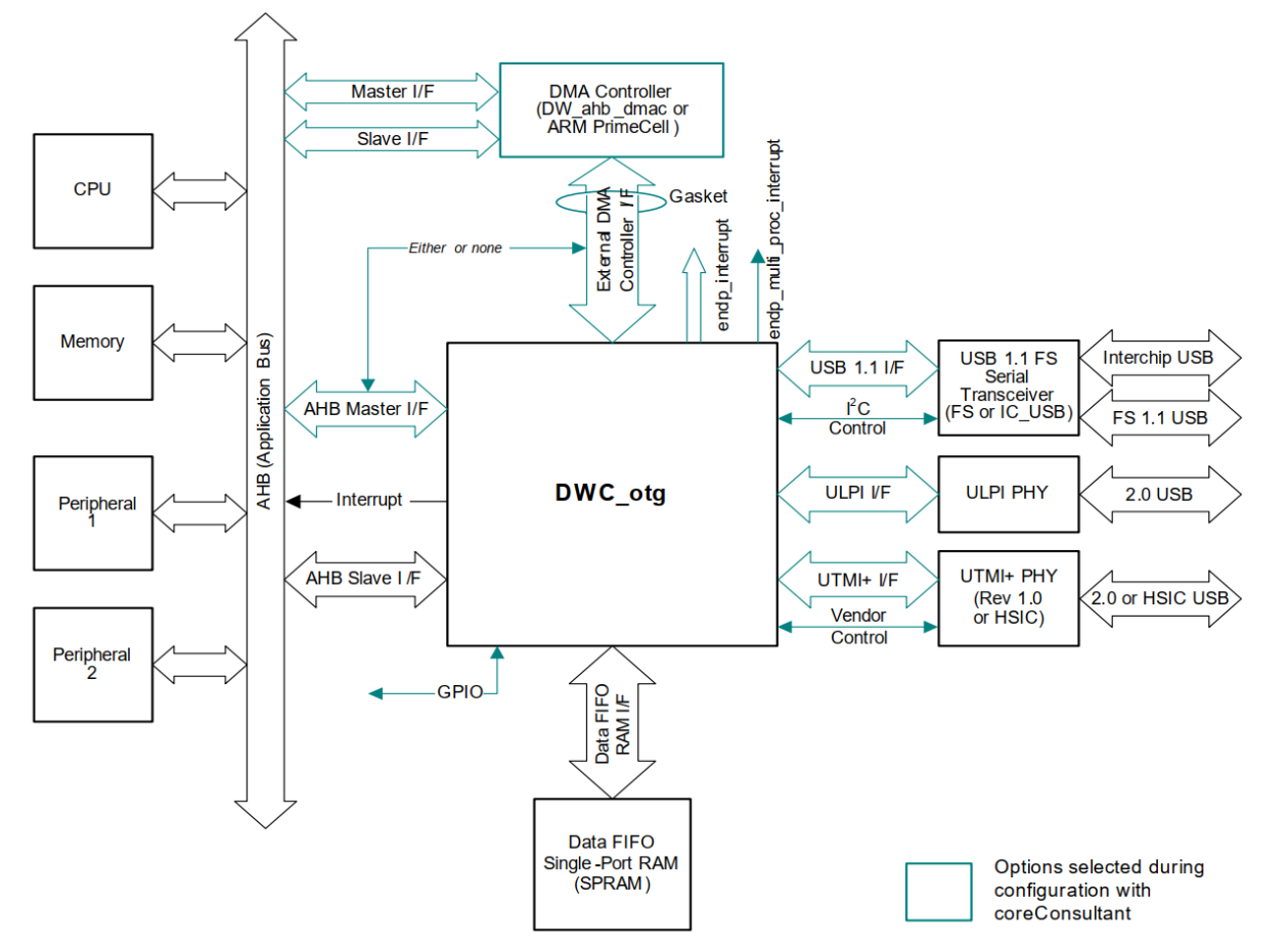
Figure 5-2 DWC2 controller system-level block diagram Figure 5-3 below illustrates the interrupt handling hierarchy of the DWC2 controller. From the figure, it can be seen that DWC2 supports device interrupt/host interrupt/OTG interrupt. These three types of interrupts also include sub-interrupts. All interrupts are connected to the chip’s interrupt processing module through a total interrupt signal.
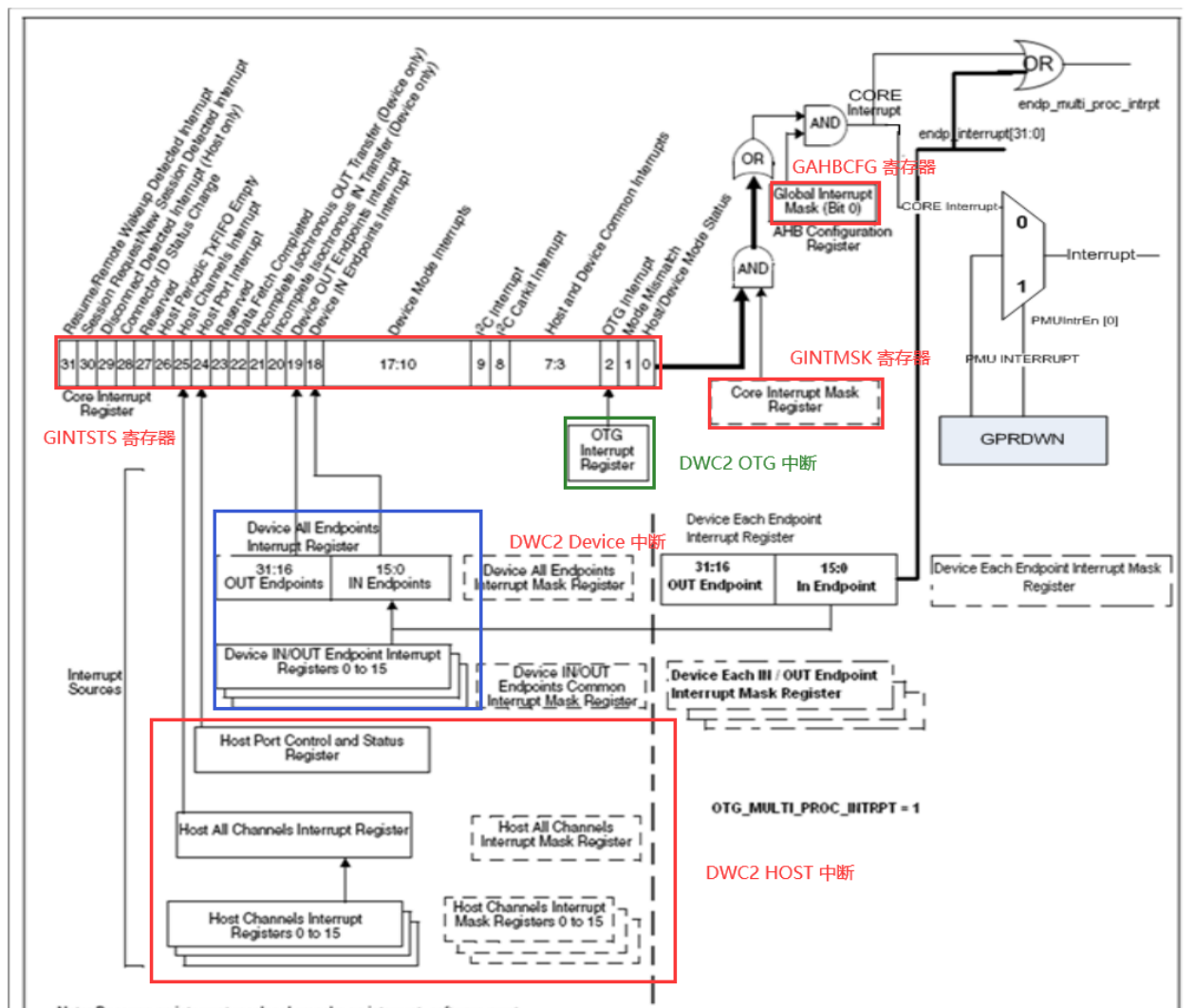
Figure 5-3 Interrupt level of DWC2 controller
5.3.1.2 USB 2.0 OTG Driver Overview
- USB 2.0 OTG Controller driver code The Rockchip platform have two sets of DWC2 controller drivers: dwc2 driver and dwc_otg_310 driver dwc2 driver: (used for most SoCs) drivers/usb/dwc2/* dwc_otg_310 driver: (Legacy driver, only used for RK3288/RK3368) drivers/usb/dwc_otg_310/*
- USB 2.0 OTG controller driver code structure description Considering Linux-4.19 and newer kernel, the DWC2 controllers of all chips have used the dwc2 driver instead of the old dwc_otg_310 driver, so this document focuses on the dwc2 driver.
USB OTG 2.0 is a Dual-Role Device controller, which supports both device and host functions and is fully compliant with OTG Supplement to USB2.0 specification, and support high-speed (480Mbps), full-speed (12Mbps), low-speed (1.5Mbps) transfer. The structure of the dwc2 driver code is as follows:
~/src/android_Q/kernel/drivers/usb/dwc2$ tree .
├── core.c (dwc2 core reset, configure core param and other general operations)
├── core.h
├── core_intr.c (dwc2 general interrupt events, including otg intr, id intr, wakeup intr,
etc.)
├── debugfs.c (dwc2 debug interface, such as printing register information)
├── debug.h
├── gadget.c (all tasks related to dwc2 gadget mode, such as gadget initialization, gadget
interrupt event)
├── hcd.c (dwc2 host mode related tasks and core init, phy init, device/host mode switching)
├── hcd_ddma.c (dwc2 descriptor DMA related tasks)
├── hcd.h
├── hcd_intr.c (handling of all interrupt events in dwc2 host mode)
├── hcd_queue.c (dwc2 host mode transmission queue processing)
├── hw.h
├── Kconfig
├── Makefile
├── pci.c (initialization of pci bus interface, Rockchip dwc2 uses AHB bus)
└── platform.c (implement dwc2 probe, initialize dwc2 lowlevel hw resources according to
core_params configuration of different chips)
5.3.1.3 USB 2.0 OTG Debug Interface
DWC2 Driver Debug Interface Example (RK3328 SoC):
rk3328_box:/sys/kernel/debug/ff580000.usb # ls
ep0   ep2out ep4out ep6out ep8in  ep9in  fifo    state
ep1in ep3in  ep5in  ep7in  ep8out ep9out regdump testmode
ep*in/out: Shows the state of the given endpoint (one is registered for each available). fifo: Show the FIFO information for the overall fifo and all the periodic transmission FIFOs. state: shows the overall state of the hardware and some general information about each of the endpoints available to the system. regdump: Gets register values of core. testmode: Modify the current usb test mode. DWC_OTG_310 Driver Debug Interface Example (RK3288 SoC):
rk3288:/sys/devices/platform/ff580000.usb # ls
busconnected  fr_interval gsnpsid   modalias       regoffset     uevent
buspower      gadget      guid      mode           regvalue      usb5
bussuspend    ggpio       gusbcfg   mode_ch_tim_en remote_wakeup wr_reg_test
devspeed      gnptxfsiz   hcd_frrem pools          spramdump
disconnect_us gotgctl     hcddump   power          subsystem
driver        gpvndctl    hprt0     rd_reg_test    test_sq
enumspeed     grxfsiz     hptxfsiz  regdump        udc

rk3328_box:/sys/devices/platform/ff580000.usb/driver # ls
bind       dwc_otg_conn_en force_usb_mode uevent vbus_status
debuglevel ff580000.usb    op_state       unbind versio
busconnected: Gets or sets the Core Control Status Register. fr_interval: On read, shows the value of HFIR Frame Interval. On write, dynamically reload HFIR register during runtime. The application can write a value to this register only after the Port Enable bit of the Host Port Control and Status register (HPRT.PrtEnaPort) has been set. gsnpsid: Gets the value of the Synopsys ID Regester. regoffset: Sets the register offset for the next Register Access. buspower: Gets or sets the Power State of the bus (0 - Off or 1 - On). guid: Gets or sets the value of the User ID Register. regvalue: Gets or sets the value of the register at the offset in the regoffset attribute. bussuspend: Suspends the USB bus. ggpio: Gets the value in the lower 16-bits of the General Purpose IO Register or sets the upper 16 bits. gusbcfg: Gets or sets the Core USB Configuration Register. mode_ch_tim_en: This bit is used to enable or disable the host core to wait for 200 PHY clock cycles at the end of Resume to change the opmode signal to the PHY to 00 after Suspend or LPM. remote_wakeup: On read, shows the status of Remote Wakeup. On write, initiates a remote wakeup of the host. When bit 0 is 1 and Remote Wakeup is enabled, the Remote Wakeup signalling bit in the Device Control Register is set for 1 milli-second. wr_reg_test: Displays the time required to write the GNPTXFSIZ register many times (the output shows the number of times the register is written). devspeed: Gets or sets the device speed setting in the DCFG register. gnptxfsiz: Gets or sets the non-periodic Transmit Size Register. spramdump: Dumps the contents of core registers. disconnect_us: On read, shows the status of disconnect_device_us. On write, sets disconnect_us which causes soft disconnect for 100us. Applicable only for device mode of operation. gotgctl: Gets or sets the Core Control Status Register. hcddump: Dumps the current HCD state.
gpvndctl: Gets or sets the PHY Vendor Control Register. hprt0: Gets or sets the value in the Host Port Control and Status Register. rd_reg_test: Displays the time required to read the GNPTXFSIZ register many times (the output shows the number of times the register is read). test_sq: Gets or sets the usage of usb controler test_sq attribute. enumspeed: Gets the device enumeration Speed. grxfsiz: Gets or sets the Receive FIFO Size Register. hptxfsiz: Gets the value of the Host Periodic Transmit FIFO. regdump: Dumps the contents of core registers. dwc_otg_conn_en: Enable or disable connect to PC in device mode. force_usb_mode: Force work mode of core (0 - Normal, 1 - Host, 2 - Device). vbus_status: Gets the Voltage of VBUS. debuglevel: Gets or sets the driver Debug Level. op_state: Gets or sets the operational State, during transations (a_host»a_peripherial and b_device=>b_host) this may not match the core but allows the software to determine transitions. version: Gets the Driver Version.
5.3.2 USB 2.0 Host Driver
5.3.2.1 USB 2.0 Host Controller framework
The USB 2.0 Host controller is composed of a USB 2.0 EHCI controller and a USB 1.1 OHCI controller. The green box in Figure 5-4 is the hardware IP optional function. The USB 2.0 Host controller of the Rockchip SoC is configured as an EHCI controller and an OHCI controller, and communicate with the USB PHY by UTMI + interface. Both EHCI and OHCI use internal DMA to access system memory via the AHB bus. EHCI is responsible for handling HighSpeed transmission transactions, and OHCI is responsible for handling FullSpeed and LowSpeed transmission transactions.
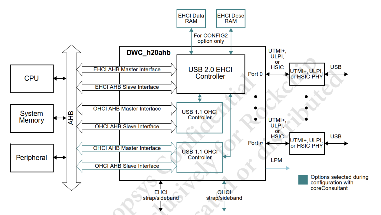
Figure 5-4 EHCI & OHCI controller system-level block diagram
5.3.2.2 USB 2.0 Host Driver Overview
- USB 2.0 Host driver code drivers/usb/host/ehci* (USB 2.0 Host Driver) drivers/usb/host/ohci* (USB 1.1/1.0 Host Driver)
- USB 2.0 Host driver code structure description The ehci driver code structure is as follows: Other ehci driver files not listed are platform ehci drivers implemented by different Vendors, such as ehci- exynos.c. Rockchip’s EHCI controller design conforms to the standard EHCI controller specifications, so the general platform ehci driver “ehci-platform.c” is used.
~/src/android_Q/kernel/drivers/usb/host$ tree
├── ehci-dbg.c (ehci debugfs debugging interface, such as printing ehci register
information)
├── ehci.h
├── ehci-hcd.c (Initialization of ehci controller, interrupt event processing, urb queue
management, etc.)
├── ehci-hub.c (control and status query of ehci root hub, bus suspend/resume)
├── ehci-mem.c (allocation and initialization of ehci mem, allocation and initialization of
qtd/qh resources)
├── ehci-pci.c (Initialization of pci bus interface, Rockchip ehci uses AHB bus, does not
use this driver)
├── ehci-platform.c (ehci universal platform driver, implement ehci probe, register ehci hcd
with usb bus, enable ehci controller)
├── ehci-q.c (processing of ehci qtd/qh transmission queue)
├── ehci-sched.c (cyclic transmission scheduling processing of ehci interrupt, iso, split
iso)
├── ehci-sysfs.c (ehci sysfs debugging interface, display companion controller, display
uframe_periodic_max)
├── ehci-timer.c (task processing related to ehci timer)
Important EHCI Structure:
static const struct hc_driver ehci_hc_driver = {
    .description =      hcd_name,
    .product_desc =     "EHCI Host Controller",
    .hcd_priv_size =    sizeof(struct ehci_hcd),
    /*
     * generic hardware linkage
     */
    .irq =          ehci_irq,
    .flags =        HCD_MEMORY | HCD_USB2 | HCD_BH,
    /*
     * basic lifecycle operations
     */
    .reset =        ehci_setup,
    .start =        ehci_run,
    .stop =         ehci_stop,
    .shutdown =     ehci_shutdown,
    /*
     * managing i/o requests and associated device resources
     */
    .urb_enqueue =      ehci_urb_enqueue,
    .urb_dequeue =      ehci_urb_dequeue,
    .endpoint_disable = ehci_endpoint_disable,
    .endpoint_reset =   ehci_endpoint_reset,
    .clear_tt_buffer_complete = ehci_clear_tt_buffer_complete,
    /*
     * scheduling support
     */
    .get_frame_number = ehci_get_frame,
    /*
     * root hub support
     */
    .hub_status_data =  ehci_hub_status_data,
    .hub_control =      ehci_hub_control,
    .bus_suspend =      ehci_bus_suspend,
    .bus_resume =       ehci_bus_resume,
    .relinquish_port =  ehci_relinquish_port,
    .port_handed_over = ehci_port_handed_over,
    /*
     * device support
     */
    .free_dev =     ehci_remove_device,
};
The structure of ochi driver code is as follows: Other ohci driver files not listed are platform ohci drivers implemented by different Vendors, such as ohci- exynos.c. The OHCI controller design of the Rockchip chip conforms to the standard OHCI controller specifications, so the general platform ohci driver “ohci-platform.c” is used.
~/src/android_Q/kernel/drivers/usb/host$ tree
├── ohci-dbg.c (ohci debugfs debugging interface, such as printing ohci register
information)
├── ohci.h
├── ohci-hcd.c (initialization of ohci controller, interrupt event processing, urb queue
management, etc.)
├── ohci-hub.c (control and status query of ohci root hub, bus suspend/resume)
├── ohci-mem.c (allocation and initialization of ohci mem, allocation and initialization of
td/ed resources)
├── ohci-pci.c (Initialization of pci bus interface, Rockchip ohci uses AHB bus, does not
use this driver file)
├── ohci-platform.c (ohci universal platform driver, implement ohci probe, register ohci hcd
with usb bus, enable ohci controller)
├── ohci-q.c (handling of ohci td/ed transmission queue)
Important OHCI Structures:
static const struct hc_driver ohci_hc_driver = {
    .description =          hcd_name,
    .product_desc =         "OHCI Host Controller",
    .hcd_priv_size =        sizeof(struct ohci_hcd),
    /*
     * generic hardware linkage
    */
    .irq =                  ohci_irq,
    .flags =                HCD_MEMORY | HCD_USB11,
    /*
    * basic lifecycle operations
    */
    .reset =                ohci_setup,
    .start =                ohci_start,
    .stop =                 ohci_stop,
    .shutdown =             ohci_shutdown,
    /*
     * managing i/o requests and associated device resources
    */
    .urb_enqueue =          ohci_urb_enqueue,
    .urb_dequeue =          ohci_urb_dequeue,
    .endpoint_disable =     ohci_endpoint_disable,
    /*
    * scheduling support
    */
    .get_frame_number =     ohci_get_frame,
    /*
    * root hub support
    */
    .hub_status_data =      ohci_hub_status_data,
    .hub_control =          ohci_hub_control,
#ifdef CONFIG_PM
    .bus_suspend =          ohci_bus_suspend,
    .bus_resume =           ohci_bus_resume,
#endif
    .start_port_reset = ohci_start_port_reset,
};
5.3.2.3 USB 2.0 Host Debug Interface
Example (RK3399 USB 2.0 EHCI/OHCI) EHCI Driver Debug Interface (Need to enable CONFIG_DYNAMIC_DEBUG)
rk3399_box:/sys/kernel/debug/usb/ehci/fe380000.usb # ls
async bandwidth periodic registers

rk3399:/sys/devices/platform/fe380000.usb # ls
companion driver_override of_node power     uevent              usb5
driver    modalias        pools   subsystem uframe_periodic_max usbmon
async: Dump a snapshot of the Async Schedule. bandwidth: Dump the HS Bandwidth Table. periodic: Dump a snapshot of the Periodic Schedule. registers: Dump Capability Registers, Interrupt Params and Operational Registers. companion: Print EHCI’s companion controller information uframe_periodic_max: Displays the maximum usable microframe bandwidth for EHCI periodic transmission, the default is 100 (unit: microseconds), and the maximum can be configured to 125 microseconds
OHCI Driver Debug Interface (Need to enable CONFIG_DYNAMIC_DEBUG)
rk3399_box:/sys/kernel/debug/usb/ohci/fe3a0000.usb # ls
async periodic registers
async: Display Control and Bulk Lists together, for simplicity periodic: Dump a snapshot of the Periodic Schedule (and load) registers: Dump driver info, then registers in Spec order and other registers mostly affect Frame Timings
5.3.3 USB 3.0 OTG Driver
5.3.3.1 USB 3.0 OTG Controller Framework
USB 3.0 OTG Controller is DWC3 Controller, as shown in Figure 5-5 below.
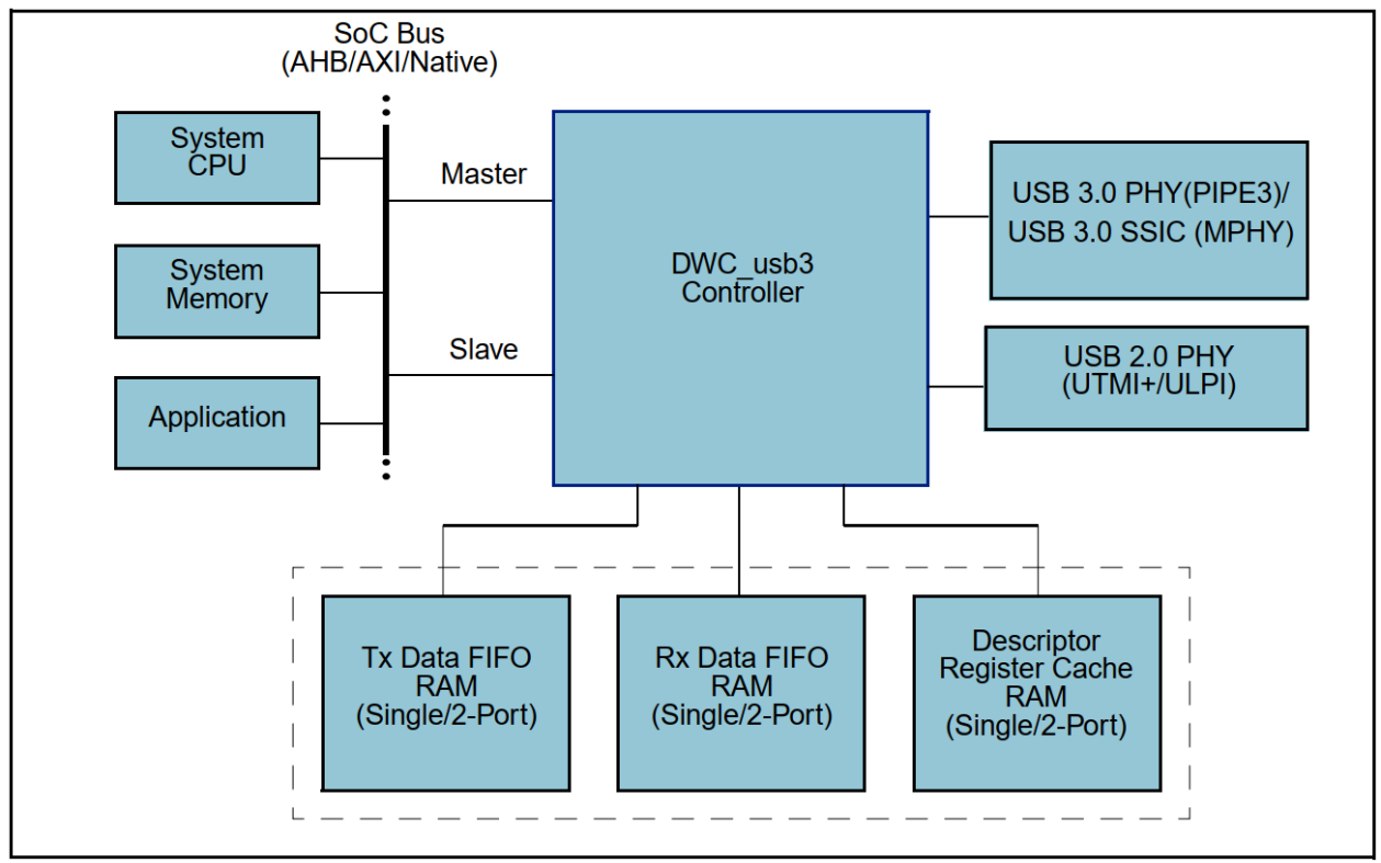
Figure 5-5 DWC3 controller system-level block diagram USB 3.0 OTG Controller is Synopsys DesignWare Core USB 3.0 Controller integrated with xHCI USB 3.0 host controller. It can act as static host, static device, USB2.0/3.0 OTG A device or B device basing on the status of input ID from USB2.0 PHY or DFP/UFP/Data Role Swap defined in USB TypeC specification. It can perform data transmission between host and device as host or device for Super-Speed/High-Speed/Full-Speed/Low-Speed. The characteristics of the USB3.0 controller are as follows: Support USB 3.0/2.0/1.1/1.0 protocol
Integrated xHCI Host controller Only DRD mode (dule role) is supported, OTG mode is not supported Device and Host functions cannot be used at the same time The USB2.0 Port and USB3.0 Port of Host can be used independently at the same time The USB2.0 Port and USB3.0 Port of Device can not be used independently at the same time Only DMA mode is supported, Slave mode is not supported Requires System Memory (Sram/Dram) xHCI is a standard USB3.0 Host controller, with the PC USB 3.0 interface. And, it can support Force USB2.0 only mode.
5.3.3.2 USB 3.0 OTG Driver Overview
- USB 3.0 OTG driver code drivers/usb/dwc3/* (USB 3.0 OTG Global core and Peripheral driver) drivers/usb/host/xhci* (USB 3.0 Host driver)
- USB 3.0 OTG driver code structure description Linux-4.19 USB DWC3 controller driver has been greatly upgraded compared to Linux-4.4, but the code file structure remains basically the same. The differences are mainly reflected in: Linux-4.19 added drd.c driver file for dynamic switching of dule rote mode; Linux-4.19 deletes the dwc3-rockchip.c file and uses the generic driver dwc3-of-simple.c instead; Linux-4.19 still retains dwc3-rockchip-inno.c, which is dedicated to RK3328/RK3228H chip; Linux-4.19 DWC3 and xHCI driver code structure is as follows:
~/src/kernel-4.19/drivers/usb/dwc3$ tree .
├── core.c (implementation of dwc3 core probe, allocate various resources, initialize
controller, PM runtime management)
├── core.h
├── debugfs.c (implementation of dwc3 debugfs debug interface)
├── debug.h
├── drd.c (dwc3 drd/otg mode dynamic switching processing)
├── dwc3-of-simple.c (dwc3 universal platform driver, realize the first level
dwc3_of_simple_probe of dwc3, and call the second level dwc3_probe of dwc3 core through
of_platform_populate)
├── dwc3-pci.c (Initialization of pci bus interface, Rockchip dwc3 uses AXI bus, does not
use this driver file)
├── dwc3-rockchip-inno.c (glue layer for RK3328/RK3228H, increase the realization of
disconnect work)
├── ep0.c (task processing of dwc3 gadget ep0)
├── gadget.c (dwc3 gadget endpoint task processing except ep0, interrupt entry function
implementation)
├── gadget.h
├── host.c (dwc3 host resource allocation, and call xhci_plat_probe of xHCI through
platform_device_add)
├── io.h
├── Kconfig
├── Makefile
├── trace.c (Dwc3 trace implementation, Linux-based trace interface)
├── trace.h
└── ulpi.c (code implementation of ulpi phy interface, Rockchip dwc3 does not use ulpi)

~/src/kernel-4.19/drivers/usb/host$ tree
├── xhci.c (initialize xhci_hc_driver, start xHCI controller, manage urb queue, etc.)
├── xhci-dbg.c (realize debug function for printing log)
├── xhci-dbgcap.c (xHCI hardware module debug capability function is not supported by
Rockchip)
├── xhci-dbgcap.h
├── xhci-debugfs.c (xHCI debugfs debugging interface)
├── xhci-debugfs.h
├── xhci-ext-caps.c (xHCI extended capability function implementation, not supported by
Rockchip)
├── xhci-ext-caps.h
├── xhci.h
├── xhci-hub.c (xHCI root hub control and status query, bus suspend/resume)
├── xhci-mem.c (xHCI mem management, including allocation, initialization, release and other
operations)
├── xhci-pci.c (Initialization of pci bus interface, Rockchip xHCI uses AXI bus, does not
use this driver file)
├── xhci-plat.c (xHCI universal platform driver, implement xhci_plat_probe, Rockchip uses
this driver)
├── xhci-plat.h
├── xhci-ring.c (management of xHCI transfer/command/event ring)
├── xhci-trace.c (xHCI trace implementation, Linux-based trace interface)
└── xhci-trace.h
Important Gadget Structure:
static const struct usb_gadget_ops dwc3_gadget_ops = {
    .get_frame      = dwc3_gadget_get_frame,
    .wakeup         = dwc3_gadget_wakeup,
    .set_selfpowered    = dwc3_gadget_set_selfpowered,
    .pullup         = dwc3_gadget_pullup,
    .udc_start      = dwc3_gadget_start,
    .udc_stop       = dwc3_gadget_stop,
};
Important Host Structure:
static const struct hc_driver xhci_hc_driver = {
    .description =      "xhci-hcd",
    .product_desc =     "xHCI Host Controller",
    .hcd_priv_size =    sizeof(struct xhci_hcd *),
    /*
     * generic hardware linkage
     */
    .irq =          xhci_irq,
    .flags =        HCD_MEMORY | HCD_USB3 | HCD_SHARED,
    /*
     * basic lifecycle operations
     */
    .reset =        NULL, /* set in xhci_init_driver() */
    .start =        xhci_run,
    .stop =         xhci_stop,
    .shutdown =     xhci_shutdown,
    /*
     * managing i/o requests and associated device resources
     */
    .urb_enqueue =      xhci_urb_enqueue,
    .urb_dequeue =      xhci_urb_dequeue,
    .alloc_dev =        xhci_alloc_dev,
    .free_dev =     xhci_free_dev,
    .alloc_streams =    xhci_alloc_streams,
    .free_streams =     xhci_free_streams,
    .add_endpoint =     xhci_add_endpoint,
    .drop_endpoint =    xhci_drop_endpoint,
    .endpoint_reset =   xhci_endpoint_reset,
    .check_bandwidth =  xhci_check_bandwidth,
    .reset_bandwidth =  xhci_reset_bandwidth,
    .address_device =   xhci_address_device,
    .enable_device =    xhci_enable_device,
    .update_hub_device =    xhci_update_hub_device,
    .reset_device =     xhci_discover_or_reset_device,
    /*
     * scheduling support
     */
    .get_frame_number = xhci_get_frame,
    /*
     * root hub support
     */
    .hub_control =      xhci_hub_control,
    .hub_status_data =  xhci_hub_status_data,
    .bus_suspend =      xhci_bus_suspend,
    .bus_resume =       xhci_bus_resume,
    /*
     * call back when device connected and addressed
     */
    .update_device =        xhci_update_device,
    .set_usb2_hw_lpm =  xhci_set_usb2_hardware_lpm,
    .enable_usb3_lpm_timeout =  xhci_enable_usb3_lpm_timeout,
    .disable_usb3_lpm_timeout = xhci_disable_usb3_lpm_timeout,
    .find_raw_port_number = xhci_find_raw_port_number,
};
5.3.3.3 USB 3.0 OTG Debug Interface
Example (Linux-4.19 RK3399 USB 3.0 OTG0)
console:/sys/kernel/debug/fe800000.dwc3 # ls
ep0in  ep1in  ep2in  ep3in  ep4in  ep5in  ep6out     lsp_dump regdump
ep0out ep1out ep2out ep3out ep4out ep5out link_state mode     testmode

console:/sys/kernel/debug/fe800000.dwc3/ep0in # ls
descriptor_fetch_queue rx_info_queue    trb_ring
event_queue            rx_request_queue tx_fifo_queue
rx_fifo_queue          transfer_type    tx_request_queue

console:/sys/kernel/debug/usb/xhci/xhci-hcd.0.auto # ls
command-ring ports          reg-ext-legsup:00   reg-op
devices      reg-cap        reg-ext-protocol:00 reg-runtime
event-ring   reg-ext-dbc:00 reg-ext-protocol:01
Common debugging nodes: mode: dr_mode read or store testmode: Set DWC3 to enter HighSpeed test mode for eye diagram test link_state: Link state read or store regdump: Dump registers of DWC3 ep*in/out: Directory of EP debug files descriptor_fetch_queue: Dump the available DescFetchQ space of EP rx_info_queue: Dump the available RXInfoQ space of EP trb_ring: Dump the TRB pool of EP event_queue: Dump the avaliable EventQ space of EP rx_request_queue: Dump the avaliable RxReqQ space of EP tx_fifo_queue: Dump the avaliable TxFIFO space of EP rx_fifo_queue: Dump the avaliable RxFIFO space of EP transfer_type: Print the Transfer Type of EP tx_request_queue: Dump the abaliable TxReqQ space of EP command-ring: Print the status information of xHCI command ring event-ring: Print the status information of xHCI event ring reg-op: Print xHCI register status information USB 3.0 OTG tracepoint
sys/kernel/debug/tracing/events/xhci-hcd sys/kernel/debug/tracing/events/dwc3 For more details, please refer to: sys/kernel/debug/tracing/README USB 3.0 OTG switch command Function: Through software method, force OTG to work in Host mode or Device mode without being affected by USB hardware circuit. Linux-4.4 USB 3.0 OTG switch command Linux-4.4 old command (only used for RK3399):
#RK3399 Type-C0 USB OTG switch command
#1.Force host mode
  echo host > sys/kernel/debug/usb@fe800000/rk_usb_force_mode
#2.Force peripheral mode
  echo peripheral > sys/kernel/debug/usb@fe800000/rk_usb_force_mode
Linux-4.4 new command (only used for RK3399/RK1808):
#RK3399 Type-C0 USB OTG switch command
#1.Force host mode
  echo host > sys/devices/platform/usb0/dwc3_mode
#2.Force peripheral mode
  echo peripheral > sys/devices/platform/usb0/dwc3_mode

#RK1808 USB OTG switch command
#1.Force host mode
  echo host > sys/devices/platform/usb/dwc3_mode
#2.Force peripheral mode
  echo peripheral > sys/devices/platform/usb/dwc3_mode
Linux-4.19 USB 3.0 OTG switch command (used for all SoCs with DWC3 Controller)
#RK3399 Type-C0 USB OTG switch command
#1.Force host mode
  echo host > sys/devices/platform/ff770000.syscon/ff770000.syscon:usb2-phy@e450/otg_mode
#2.Force peripheral mode
  echo peripheral > sys/devices/platform/ff770000.syscon/ff770000.syscon:usb2-
phy@e450/otg_mode

#For other SoCs, the method is similar, just search for the "otg_mode" node under the
sys/devices/platform path, and then set the node.
Linux-5.10 USB 3.0 OTG switch command (used for all SoCs with DWC3 Controller)
#RK3588 Type-C0 USB OTG switch command
#Method1. [Legacy] use usb phy node
#1.Force host mode
  echo host > /sys/devices/platform/fd5d0000.syscon/fd5d0000.syscon:usb2-phy@0/otg_mode
#2.Force peripheral mode
  echo peripheral > /sys/devices/platform/fd5d0000.syscon/fd5d0000.syscon:usb2-
phy@0/otg_mode

#Method2.[New] use usb controller node
#1.Force host mode
  echo host > /sys/kernel/debug/usb/fc000000.usb/mode
#2.Force peripheral mode
  echo device > /sys/kernel/debug/usb/fc000000.usb/mode

#For other SoCs, the method is similar, just search for the "otg_mode" or "mode" node under
the sys path, and then set the node.
5.4 USB GPIO Driver and Software Processing Flow
Linux supports USB GPIO drivers, including:
- The usb-conn-gpio driver Documentation/devicetree/bindings/connector/usb-connector.yaml drivers/usb/common/usb-conn-gpio.c It manages vbus/id GPIO interrupts and sets the USB Device/Host mode through usb_role_switch, supporting the SDP charging role notification feature.
- The extcon-usb-gpio driver Documentation/devicetree/bindings/extcon/extcon-usb-gpio.txt drivers/extcon/extcon-usb-gpio.c It manages vbus/id GPIO interrupts and sets the EXTCON_USB/EXTCON_USB_HOST state through extcon events.
- The phy-gpio-vbus-usb driver drivers/usb/phy/phy-gpio-vbus-usb.c It manages the vbus regulator and manages the usb gadget connection (usb_gadget_vbus_connect/usb_gadget_vbus_disconnect) based on the vbus state. The Rockchip SDK uses the extcon-usb-gpio.c driver to interact with the USB2 PHY and controller through extcon events, completing USB Device hot-plug detection and OTG mode switching.
5.4.1 USB VBUSDET GPIO Software Processing Flow
Based on the RK3506G EVB1 design, referring to the USB VBUSDET GPIO Hardware Circuit Design, a transistor is added between the USB interface input VBUS and the VBUSDET GPIO, which inverts the input VBUS level. The software processing flow for hot-plugging of USB Device is as follows:
- USB connection to PC: VBUS transitions from low to high level –> triggers GPIO interrupt –> executes GPIO interrupt handler function, checks GPIO is low level –> sends extcon message to USB2 PHY driver –> calls rockchip_usb2phy_usb_bvalid_enable() to set GRF bvalid signal high –> triggers bvalid rise interrupt –> executes rockchip_usb2phy_bvalid_irq interrupt handler function, calls otg_sm_work –> performs charging detection and executes resume phy operation –> Pullup DP and start enumeration.
- USB disconnection from PC: VBUS transitions from high to low level –> triggers GPIO interrupt –> executes GPIO interrupt handler function, checks GPIO is high level –> sends extcon message to USB2 PHY driver –> calls rockchip_usb2phy_usb_bvalid_enable() to control GRF bvalid signal low (simultaneously, it will also trigger DWC2 controller device disconnect interrupt) –> otg_sm_work polls GRF bvalid register status, detects bvalid signal low –> executes suspend phy operation.
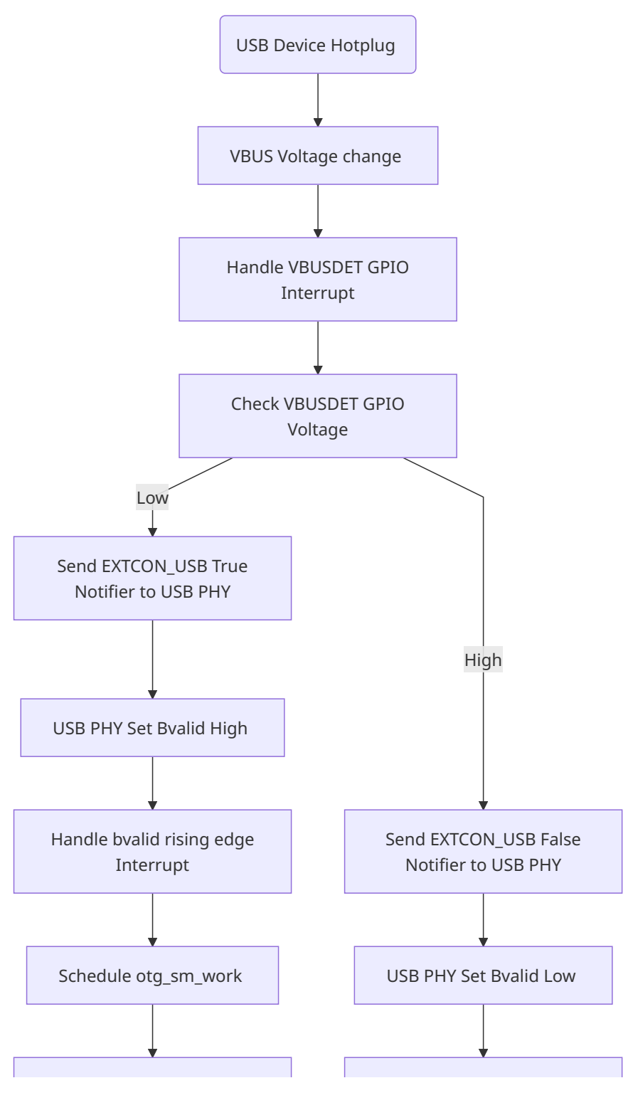
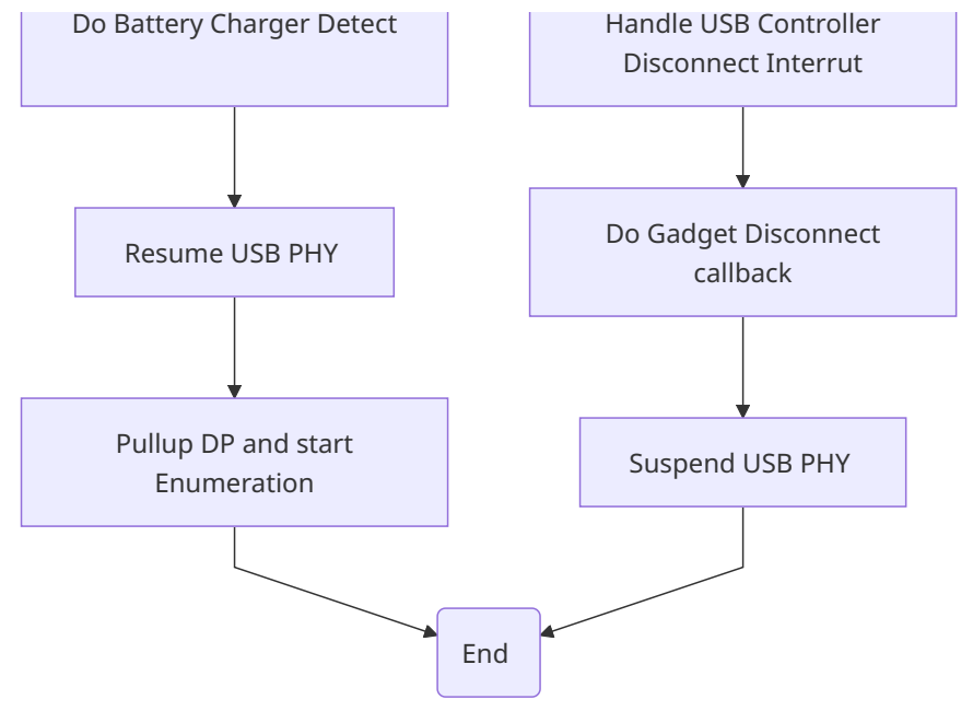
5.4.2 USB OTG_ID GPIO Software Processing Flow
- OTG cable insertion: ID changes from the default high level to low level –> triggers GPIO interrupt –> executes GPIO interrupt handling function, checks ID is low level –> sends extcon message to USB2 PHY driver –> sets GRF IDDIG register to low –> triggers DWC2 controller ID interrupt –> performs OTG host mode initialization.
- OTG cable removal: ID changes from low level to high level –> triggers GPIO interrupt –> executes GPIO interrupt handling function, checks ID is high level –> sends extcon message to USB2 PHY driver - -> sets GRF IDDIG register to high –> triggers DWC2 controller ID interrupt –> performs OTG device mode initialization.
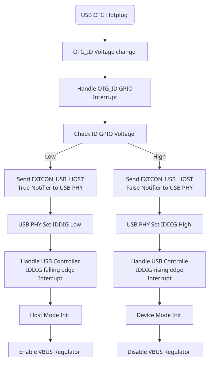

6. Android USB Gadget Configuration
6.1 USB Gadget Configfs Framework
Since Linux-3.11, USB Gadgets have been configured in the framework of Configfs, and the android.c file in the Gadget directory has been deleted from the kernel. Device class drivers that support the Configfs framework are moved to the directory drivers/usb/gadget/function . For instructions on how to use Android ConfigFS Gadgets, please refer to Linux documentations: Documentation/ABI/testing/configfs-usb-gadget-xxxx.txt Documentation/filesystems/configfs/configfs.txt Documentation/usb/gadget_configfs.txt Documentation/usb/gadget-testing.txt Kernel USB Gadget Configfs Interface TIZEN USB https://wiki.linaro.org/LMG/Kernel/AndroidConfigFSGadgets
6.2 USB Gadget Configuration File
USB-related scripts in Android include:
init.usb.rc
init.usb.configfs.rc
init.rk30board.usb.rc
fstab.rk30board.bootmode.emmc
- init.usb.rc: Android standard RC files, no need change.
- fstab.rk30board.bootmode.emmc: Android fstab file, it can be used to configure the mount paths of sdcard and usb storage. On Rockchip platform, the Vold can use wildcard to search and match USB mount paths automatically.
# for USB 2.0
/devices/platform/*.usb*         auto vfat defaults     voldmanaged=usb:auto
# for USB 3.0
/devices/platform/usb@*/*.dwc3*    auto vfat defaults     voldmanaged=usb:auto
- init.rk30board.usb.rc and init.usb.configfs.rc: used for usb functions configuration.
on boot
    mkdir /dev/usb-ffs 0770 shell shell
    mkdir /dev/usb-ffs/adb 0770 shell shell
    mount configfs none /config
    mkdir /config/usb_gadget/g1 0770 shell shell
    write /config/usb_gadget/g1/idVendor 0x2207
    write /config/usb_gadget/g1/bcdDevice 0x0310
    write /config/usb_gadget/g1/bcdUSB 0x0200
    mkdir /config/usb_gadget/g1/strings/0x409 0770
    write /config/usb_gadget/g1/strings/0x409/serialnumber ${ro.serialno}
    write /config/usb_gadget/g1/strings/0x409/manufacturer ${ro.product.manufacturer}
    write /config/usb_gadget/g1/strings/0x409/product ${ro.product.model}
    mkdir /config/usb_gadget/g1/functions/accessory.gs2
    mkdir /config/usb_gadget/g1/functions/audio_source.gs3
    mkdir /config/usb_gadget/g1/functions/ffs.adb
    mkdir /config/usb_gadget/g1/functions/mtp.gs0
    mkdir /config/usb_gadget/g1/functions/ptp.gs1
    mkdir /config/usb_gadget/g1/functions/rndis.gs4
    write /config/usb_gadget/g1/functions/rndis.gs4/wceis 1
    mkdir /config/usb_gadget/g1/functions/midi.gs5
    mkdir /config/usb_gadget/g1/configs/b.1 0770 shell shell
    mkdir /config/usb_gadget/g1/configs/b.1/strings/0x409 0770 shell shell
    write /config/usb_gadget/g1/os_desc/b_vendor_code 0x1
    write /config/usb_gadget/g1/os_desc/qw_sign "MSFT100"
    write /config/usb_gadget/g1/configs/b.1/MaxPower 500
    symlink /config/usb_gadget/g1/configs/b.1 /config/usb_gadget/g1/os_desc/b.1
    mount functionfs adb /dev/usb-ffs/adb uid=2000,gid=2000
    setprop sys.usb.configfs 1
    setprop sys.usb.controller "fe800000.dwc3"

on property:sys.usb.config=none && property:sys.usb.configfs=1
    write /config/usb_gadget/g1/os_desc/use 0
    setprop sys.usb.ffs.ready 0

on property:init.svc.adbd=stopped
    setprop sys.usb.ffs.ready 0

on property:sys.usb.config=mtp && property:sys.usb.configfs=1
    write /config/usb_gadget/g1/functions/mtp.gs0/os_desc/interface.MTP/compatible_id "MTP"
    write /config/usb_gadget/g1/os_desc/use 1
    write /config/usb_gadget/g1/idProduct 0x0001

on property:sys.usb.config=mtp,adb && property:sys.usb.configfs=1
    write /config/usb_gadget/g1/functions/mtp.gs0/os_desc/interface.MTP/compatible_id "MTP"
    write /config/usb_gadget/g1/os_desc/use 1
    write /config/usb_gadget/g1/idProduct 0x0011
The three attributes of serialnumber, manufacturer and product are dynamically configured by the Android application layer. If the serialnumber is not configured successfully, it may cause ADB to be unusable. “setprop sys.usb.controller” is used to enable the corresponding USB controller of Gadget. For RK3399, it has two OTG controllers, both of them can support the function of USB Gadget. But because the current architecture of USB Gadget Driver only supports one USB controller, it is necessary to configure the corresponding USB controller according to the actual product requirements, such as RK3399 Android SDK, which configures the Type-C0 as the USB Gadget function by default.
setprop sys.usb.controller "fe800000.usb"
Note: The Kernel USB Gadget Framework only supports one USB Gadget at the same time. And RK3399 supports two Type-C USB 3.0 OTG controllers (Type-C0 and Type-C1). If you want to use Type-C1 USB 3.0 as USB Gadget instead of Type-C0, simply change two configurations:
- Use Type-C1 controller name “fe900000.usb” instead of “fe800000.usb” in init.rk30board.usb.rc.
setprop sys.usb.controller "fe900000.usb"
- set dr_mode = “otg” in usbdrd_dwc3_1 node in DTS.
&usbdrd_dwc3_1 {
        status = "okay";
        dr_mode = "otg";  /* Configure Type-C1 USB Controller to OTG mode */
        extcon = <&fusb1>; /* Note: extcon should be configured according to actual
hardware */
};
6.3 USB VID And PID Configuration
USB VID and PID configuration need to follow the following principles: VID is fixed at 0x2207 (authorized by USB-IF) PID can be defined according to product requirements, but the upper 8 bits must be 0 to avoid conflicts with Maskrom/Loader USB PID VID and PID of accessory need to be configured as defined by Google USB-IF stipulates that VID is unique to each Vendor, and the same VID cannot be authorized for different Vendors VID and PID commonly used in the Andorid platform are defined as follows:
| USB Function | VID | PID |
|---|---|---|
| MTP | 0x2207 | 0x0001 |
| PTP | 0x2207 | 0x0002 |
| RNDIS | 0x2207 | 0x0003 |
| MIDI | 0x2207 | 0x0004 |
| UVC | 0x2207 | 0x0005 |
| ADB | 0x2207 | 0x0006 |
| MTP,ADB | 0x2207 | 0x0011 |
| PTP,ADB | 0x2207 | 0x0012 |
| RNDIS,ADB | 0x2207 | 0x0013 |
| MIDI,ADB | 0x2207 | 0x0014 |
| UVC,ADB | 0x2207 | 0x0015 |
| ACCESSORY | 0x18d1 | 0x18d1 |
| ACCESSORY,ADB | 0x18d1 | 0x2d01 |
6.4 USB Gadget Debug Interface
Configfs Configure Interface The kernel provides device nodes to view key configuration information for USB Gadgets, as follows:
root@rk3399:/config/usb_gadget/g1 # ls
UDC          bDeviceProtocol bMaxPacketSize0 bcdUSB  functions idVendor strings
bDeviceClass bDeviceSubClass bcdDevice       configs idProduct os_desc
Refer to Documentation/usb/gadget_configfs.txt In order to enable the gadget it must be bound to a UDC (USB Device Controller).
echo <udc name> > UDC
#where <udc name> is one of those found in /sys/class/udc/*
Example: Bind Type-C0 USB Device Contoller in RK3399 to UDC
echo fe800000.dwc3 > config/usb_gadget/g1/UDC
Unbind USB Device Controller
echo none > config/usb_gadget/g1/UDC
View USB Device Connection Status
rk3399:/sys/class/udc/fe800000.dwc3 # ls
a_alt_hnp_support device          is_selfpowered srp
a_hnp_support     function        maximum_speed  state
b_hnp_enable      is_a_peripheral power          subsystem
current_speed     is_otg          soft_connect   uevent

rk3399:/sys/class/android_usb/android0 # ls
f_audio_source f_midi power state subsystem uevent
7. USB Common Debug Methods And Commands
7.1 USB Common Debug Methods
- Common USB Debug Instruments And Software Tools Multimeter: for simple voltage test, such as: USB VBUS, OTG_ID and USB PHY power supply. High-bandwidth oscilloscope: used to measure the signal quality of the USB eye diagram, USB charging detection and handshake signals, USB VBUS voltage collapse, etc. USB protocol analyzer: Analyze the USB communication protocol flow, and locate whether it is a host problem or a device problem. Windows tools: BusHound software is used to grab USB bus packets; Usbview software is used to view detailed descriptor information of USB devices. Linux tools: usbmon is a tool for grabbing USB bus packets; vusb-analyzer graphical tool is used to parse the data captured by usbmon; lsusb command is used to view detailed descriptor information of USB devices. For more information, please refer to the documentation: Documentation/usb/usbmon.txt USB Debugging and Profiling Techniques
- Common USB Debug Interface Sysfs entry in host: /sys/bus/usb/* (view USB devices and drivers supported by the system) Debugfs entry in host: /sys/kernel/debug/usb/devices (view all USB device information on the USB bus) /sys/kernel/debug/*.dwc3 (DWC3 controller debug interface) /sys/kernel/debug/usb/usbmon (USBMon packet capture tool) /sys/kernel/debug/usb/xhci (xHCI controller debug interface) /sys/kernel/debug/usb/uvcvideo (UVC device debug interface) Debugfs for controllers: refer to USB 2.0 OTG Debug Interface, USB 2.0 Host Debug Interface, USB 3.0 OTG Debug Interface trace for usb gadget/dwc3/xHCI: /sys/kernel/debug/tracing/events/gadget (trace Gadget Driver interacting with Device Controller Driver) /sys/kernel/debug/tracing/events/dwc3 (trace DWC3 controller transmission process) /sys/kernel/debug/tracing/events/xhci-hcd (trace xHCI controller transmission process) Print usb host uvc log: echo 0xffff>/sys/module/uvcvideo/parameters/trace Print usb devio driver log: echo 1>/sys/module/usbcore/parameters/usbfs_snoop
7.2 USB Common Commands
This chapter mainly describes the specific commands for Rockchip USB driver USB, including 2.0 OTG switch command, USB 3.0 OTG switch command, USB 3.0 force USB 2.0 only command and USB eye diagram test command. USB 2.0 OTG switch command Function: Through software method, force USB 2.0 OTG to Host mode or Device mode without being affected by OTG ID level. For the USB 2.0 OTG switch command, please refer to the description of the USB 2.0 PHY debug interface in USB 2.0 PHY Driver. USB 3.0 OTG switch command Function: Through software method, force USB 3.0 OTG to Host mode or Device mode without being affected by OTG ID level or Type-C interface. For the USB 3.0 OTG switch command, please refer to the USB 3.0 OTG switch command description in USB 3.0 OTG Debug Interface. USB 3.0 force USB 2.0 only command Function: Force USB 3.0 Host controller and PHY to work in USB 2.0 only mode. For USB 3.0 force USB 2.0 only command, please refer to USB 3.0 PHY drivers. USB eye diagram test command Function: Set the USB 3.0/2.0 controller to test mode. For the USB eye diagram test command, please refer to the document: “Rockchip_Developer_Guide_USB_SQ_Test_CN”
7.3 Methods to Disable USB Low Power Mechanism
In order to control the dynamic runtime power consumption of the USB module, the Rockchip SDK platform natively supports a low power mechanism known as USB auto-suspend. When the USB is not connected or there is no data transfer, the USB controller and PHY will automatically enter suspend mode to reduce power consumption. It is important to note that for the USB low power mechanism to function properly, both the USB Host and Device must adhere to the USB protocol’s auto-suspend and resume behavior. If the product focuses more on the stability and compatibility of USB communication, consider disabling the USB low power mechanism.
7.3.1 Disable the auto-suspend feature of USB Host and peripherals
Applicable scope: All USB Host controllers (DWC2/DWC3-xHCI/EHCI/OHCI), all external USB HUBs, specific USB Cameras. TIPS: When debugging autosuspend compatibility issues, you can dynamically disable all USB autosuspend features by using the following commands to quickly troubleshoot the problem. for i in $(find /sys -name control | grep usb);do echo on > $i;echo “echo on > $i”;done;
Disable autosuspend for all USB controllers and all USB HUB peripherals Note: This method cannot disable the auto-suspend function of USB Cameras Method 1. Add usbcore.autosuspend=-1 in CMDLINE Take RK3588 Linux-5.10 as an example:
arch/arm64/boot/dts/rockchip/rk3588-android.dtsi
chosen: chosen {
        bootargs = "earlycon=uart8250,mmio32,0xfeb50000 console=ttyFIQ0
irqchip.gicv3_pseudo_nmi=0 rcupdate.rcu_expedited=1 rcu_nocbs=all
usbcore.autosuspend=-1";
};
Method 2. Modify the usb_autosuspend_delay in the driver Take Linux-5.10 as an example:
diff --git a/drivers/usb/core/usb.c b/drivers/usb/core/usb.c
index 3500e3c94c4b..3a90d3a92c0a 100644
--- a/drivers/usb/core/usb.c
+++ b/drivers/usb/core/usb.c
@@ -63,7 +63,7 @@ EXPORT_SYMBOL_GPL(usb_disabled);

 #ifdef CONFIG_PM
 /* Default delay value, in seconds */
-static int usb_autosuspend_delay = CONFIG_USB_AUTOSUSPEND_DELAY;
+static int usb_autosuspend_delay = -1;
 module_param_named(autosuspend, usb_autosuspend_delay, int, 0644);
 MODULE_PARM_DESC(autosuspend, "default autosuspend delay");
Disable the autosuspend for specific USB HUB peripherals Method: Add the specific USB hub to hub_id_table[] and set id->driver_info = HUB_QUIRK_DISABLE_AUTOSUSPEND Example: Disable the auto-suspend feature for CYPRESS CY7C65632 USB HUB (VID = 0x04b4, PID = 0x6570)
diff --git a/drivers/usb/core/hub.c b/drivers/usb/core/hub.c
index fc7d6cdacf16..df8e69e60aaf 100644
--- a/drivers/usb/core/hub.c
+++ b/drivers/usb/core/hub.c
@@ -41,6 +41,8 @@
 #define USB_VENDOR_GENESYS_LOGIC               0x05e3
 #define USB_VENDOR_SMSC                                0x0424
 #define USB_PRODUCT_USB5534B                   0x5534
+#define USB_VENDOR_CYPRESS                     0x04b4
+#define USB_PRODUCT_CY7C65632                  0x6570
 #define HUB_QUIRK_CHECK_PORT_AUTOSUSPEND       0x01
 #define HUB_QUIRK_DISABLE_AUTOSUSPEND          0x02

@@ -5697,6 +5699,11 @@ static const struct usb_device_id hub_id_table[] = {
       .idProduct = USB_PRODUCT_USB5534B,
       .bInterfaceClass = USB_CLASS_HUB,
       .driver_info = HUB_QUIRK_DISABLE_AUTOSUSPEND},
+    { .match_flags = USB_DEVICE_ID_MATCH_VENDOR
+                   | USB_DEVICE_ID_MATCH_PRODUCT,
+      .idVendor = USB_VENDOR_CYPRESS,
+      .idProduct = USB_PRODUCT_CY7C65632,
+      .driver_info = HUB_QUIRK_DISABLE_AUTOSUSPEND},
Disable the auto-suspend feature for specific USB Cameras (UVC & UAC) The mechanism for enabling auto-suspend for USB Cameras is implemented by the driver drivers/media/usb/uvc/uvc_driver.c calling the usb_enable_autosuspend interface. By default, the driver enables auto-suspend for all USB Cameras. To disable the auto-suspend feature for a specific USB Camera, you need to add USB_QUIRK_AUTO_SUSPEND. Note: The latest Upstream Mainline driver uses UVC_QUIRK_DISABLE_AUTOSUSPEND. Example. Disable the auto-suspend feature for USB Camera (VID = 0x05a3, PID = 0x9230)
diff --git a/drivers/usb/core/quirks.c b/drivers/usb/core/quirks.c
index 76ac5d6555ae..d799e93b9a0d 100644
--- a/drivers/usb/core/quirks.c
+++ b/drivers/usb/core/quirks.c
@@ -322,6 +322,9 @@ static const struct usb_device_id usb_quirk_list[] = {
        /* Alcor Micro Corp. Hub */
        { USB_DEVICE(0x058f, 0x9254), .driver_info = USB_QUIRK_RESET_RESUME },

+       /* HD Camera Manufacturer */
+       { USB_DEVICE(0x05a3, 0x9230), .driver_info = USB_QUIRK_AUTO_SUSPEND },
7.3.2 Disable DWC3 Host mode USB2 LPM Feature
Applicable Scope: All chips that support DWC3 controllers, effective only when DWC3 is operating in Host mode. Method: Add the property snps,usb2-lpm-disable in the dtsi usb dwc3 controller node. Take RK3568 Linux-5.10 as an example:
&usbdrd_dwc3 {
        snps,usb2-lpm-disable;
};

&usbhost_dwc3 {
        snps,usb2-lpm-disable;
};
7.3.3 Disable DWC3 Device mode USB2 LPM Feature
Applicable Scope: All chips that support DWC3 controllers, effective only when DWC3 is operating in Device mode. Method: Add the property snps,usb2-gadget-lpm-disable in the dtsi usb dwc3 controller node. Take RK3568 Linux-5.10 as an example:
&usbdrd_dwc3 {
        snps,usb2-gadget-lpm-disable;
};
7.3.4 Disable DWC3 Suspend USB2/USB3 PHY Feature
Applicable Scope: All chips that support DWC3 controllers, effective in both Host and Device modes. Method: Add the properties snps,dis_u2_susphy_quirk and snps,dis_u3_susphy_quirk in the dtsi usb dwc3 controller node. Take RK3568 Linux-5.10 as an example:
&usbdrd_dwc3 {
        snps,dis_u2_susphy_quirk;
        snps,dis_u3_susphy_quirk;
};

&usbhost_dwc3 {
        snps,dis_u2_susphy_quirk;
        snps,dis_u3_susphy_quirk;
};
7.3.5 Disable USB 2.0 PHY Charging Detection and Dynamic Suspend Feature
Applicable Scope: All chips using the driver drivers/phy/rockchip/phy-rockchip-inno-usb2.c Example 1. Disable the charging detection feature of rk3568 usb2 phy0 otg port (which will also disable the dynamic entry into suspend feature)
&u2phy0_otg {
        rockchip,vbus-always-on;
};
Example 2. Disable dynamic entry into suspend for rk3568 usb2 phy0 otg port while retaining the charging detection mechanism.
&u2phy0_otg {
        rockchip,dis-u2-susphy;
};
7.4 Method for Adding USB Peripheral Quirks
To improve the compatibility of the Linux USB driver with various peripherals, the USB core and USB device class drivers support adding quirks information for specific peripherals to handle issues with special devices. Common USB peripherals include: USB flash drives, USB HUBs, USB HIDs, USB Cameras, USB Audio devices.
7.4.1 Adding USB Quirks in the Linux Kernel
There are two primary methods for adding USB peripheral quirks in the Linux kernel:
- Modifying Quirks Directly in the Driver File: This method involves directly editing the quirks driver file and is suitable for non-GKI (General Kernel Interface) platforms.
- Using Module Parameters: This method involves passing parameters to the module and is applicable for both GKI and non-GKI platforms. Method 1: Modifying Quirks Directly in the Driver File
- Identify the Device: Determine the Vendor ID (VID) and Product ID (PID) of the USB device that requires a quirk.
- Locate the Quirks Table: Find the appropriate quirks table in the USB driver source code. This could be in files like drivers/usb/core/quirks.c for general devices or drivers/usb/storage/unusual_devs.h for USB Mass Storage devices.
- Add a New Entry: Add a new entry to the quirks table with the VID, PID, and the specific quirk flags needed. Example.
- Add USB core quirks
include/linux/usb/quirks.h
drivers/usb/core/quirks.c

/* Lists of quirky USB devices */
static const struct usb_device_id usb_quirk_list[] = {
        { USB_DEVICE(0x0204, 0x6025), .driver_info = USB_QUIRK_RESET_RESUME },
        { USB_DEVICE(0x21c4, 0x0cd1), .driver_info = USB_QUIRK_NO_LPM },
};

static const struct usb_device_id usb_interface_quirk_list[] = {
        { USB_VENDOR_AND_INTERFACE_INFO(0x046d, USB_CLASS_VIDEO, 1, 0),
          .driver_info = USB_QUIRK_RESET_RESUME },
};

static const struct usb_device_id usb_endpoint_ignore[] = {
        { USB_DEVICE_INTERFACE_NUMBER(0x06f8, 0xb000, 5), .driver_info = 0x01 },
};
- Add USB storage quirks
include/linux/usb_usual.h
drivers/usb/storage/unusual_devs.h   /* Driver for USB Mass Storage compliant devices
*/
drivers/usb/storage/unusual_uas.h    /* Driver for USB Attached SCSI devices - Unusual
Devices File */

/* Example of USB Mass Storage unusual device */
UNUSUAL_DEV(0x0951, 0x1697, 0x0100, 0x0100,
                    "Kingston",
                    "DT Ultimate G3",
                    USB_SC_DEVICE, USB_PR_DEVICE, NULL,
                    US_FL_NO_WP_DETECT)

/* Example of USB Attached SCSI unusual device */
UNUSUAL_DEV(0x0b05, 0x1932, 0x0000, 0x9999,
                    "ASUS",
                    "External HDD",
                    USB_SC_DEVICE, USB_PR_DEVICE, NULL,
                    US_FL_IGNORE_UAS)
- Add USB HUB quirks
drivers/usb/core/hub.c

/* Example of USB HUB unusual device */
static const struct usb_device_id hub_id_table[] = {
        { .match_flags = USB_DEVICE_ID_MATCH_VENDOR
                       | USB_DEVICE_ID_MATCH_PRODUCT
                       | USB_DEVICE_ID_MATCH_INT_CLASS,
          .idVendor = USB_VENDOR_SMSC,
          .idProduct = USB_PRODUCT_USB5534B,
          .bInterfaceClass = USB_CLASS_HUB,
          .driver_info = HUB_QUIRK_DISABLE_AUTOSUSPEND},
};
- Add USB HID quirks
include/linux/hid.h
drivers/hid/hid-quirks.c

/* Example of USB HID unusual device */
static const struct hid_device_id hid_quirks[] = {
        { HID_USB_DEVICE(USB_VENDOR_ID_LOGITECH, USB_DEVICE_ID_LOGITECH_C007),
HID_QUIRK_ALWAYS_POLL },
};
- Add USB Camera quirks
drivers/media/usb/uvc/uvcvideo.h
drivers/media/usb/uvc/uvc_driver.c

/* Example of USB Camera unusual device */
static const struct usb_device_id uvc_ids[] = {
        { .match_flags          = USB_DEVICE_ID_MATCH_DEVICE
                                | USB_DEVICE_ID_MATCH_INT_INFO,
          .idVendor             = 0x05c8,
          .idProduct            = 0x0403,
          .bInterfaceClass      = USB_CLASS_VIDEO,
          .bInterfaceSubClass   = 1,
          .bInterfaceProtocol   = 0,
          .driver_info          = (kernel_ulong_t)&uvc_quirk_fix_bandwidth },
};
- Add USB Audio quirks
sound/usb/usbaudio.h
sound/usb/quirks.c

/* Example of USB Audio unusual device */
static const struct usb_audio_quirk_flags_table quirk_flags_table[] = {
        DEVICE_FLG(0x046d, 0x084c, /* Logitech ConferenceCam Connect */
                   QUIRK_FLAG_GET_SAMPLE_RATE | QUIRK_FLAG_CTL_MSG_DELAY_1M),
};
Method 2. Passing Parameters through Module Parameters Reference Kernel Document: Documentation/admin-guide/kernel-parameters.txt for descriptions related to usbcore, usbhid, and usb-storage. Working Mechanism:
- Parse usb quirks: During the kernel startup phase, call quirks_param_ops -> quirks_param_set -> Create a quirk_list and parse usb quirks from the cmdline parameters, then add the parsed quirk information to the quirk_list;
- Match usb quirks: During the usb enumeration phase, When enumerating usb devices, the driver drivers/usb/core/hub.c executes hub_port_init -> usb_detect_quirks -> usb_detect_dynamic_quirks, searches for the usb device’s vid/pid in the quirk_list, if a match is found, the corresponding flags from the quirk_list are passed to the usb device class driver. Example 1. GKI Platform Disable the USB auto-suspend feature on the GKI platform, disable the LPM feature for VID:PID(325d:6410), disable the sleep wake reset function for VID:PID(058f:6387), disable the REPORT_OPCODES function for VID:PID(174c:x55aa), disable the UAS function for VID:PID(0bc2:2321), and set the MAX_SECTORS_64 and IGNORE_RESIDUE quirk attributes for VID:PID(05e3:0749). Add quirks configuration in device/rockchip/common/modules/make_boot.mk.
ifeq ($(BOARD_BUILD_GKI),true)
# When GKI enable, pass param to usb through cmdline
# ref:Documentation/admin-guide/kernel-parameters.txt
BOARD_KERNEL_CMDLINE += usbcore.autosuspend=-1
BOARD_KERNEL_CMDLINE += usbcore.quirks=325d:6410:k,058f:6387:e
BOARD_KERNEL_CMDLINE += usb-storage.quirks=174c:x55aa:f,0bc2:2321:u,05e3:0749:mr
endif
Example 2. Non-GKI Platform Disable the USB auto-suspend feature on the RK3588 platform.
arch/arm64/boot/dts/rockchip/rk3588-android.dtsi
chosen: chosen {
        bootargs = "earlycon=uart8250,mmio32,0xfeb50000 console=ttyFIQ0
irqchip.gicv3_pseudo_nmi=0 rcu  usbcore.autosuspend=-1";
};
7.4.2 View USB quirks
After the system boots, check the USB quirks information through the following kernel nodes.
cat /proc/cmdline
cat /sys/module/usbcore/parameters/quirks
cat /sys/module/usb_storage/parameters/quirks
cat /sys/module/usbhid/parameters/quirks
cat /sys/module/uvcvideo/parameters/quirks
cat /sys/module/snd_usb_audio/parameters/quirk_flags
8. Analysis of Common USB Questions
8.1 Device Enumeration Log
8.1.1 USB 2.0 OTG Normal Boot Log
Default mode is device when booting without USB cable.
[    8.764441]otg id chg last id -1 currentid 67108864
[    8.764925] PortPower off
[    8.866923] Using Buffer DMA mode
[    8.867280] Periodic Transfer Interrupt Enhancement- disabled
[    8.867787] Multiprocessor InterruptEnhancement - disabled
[    8.868294] OTG VER PARAM: 0, OTG VER FLAG: 0
[    8.868700] ^^^^^^^^^^^^^^^^^Device Mode
8.1.2 USB 2.0 Device Normal Connection Log
[  133.368479] ***vbusdetect*
[ 133.500590] Using Buffer DMA mode
[  133.500886] Periodic Transfer InterruptEnhancement - disabled
[  133.501391] Multiprocessor InterruptEnhancement - disabled
[  133.501875] OTG VER PARAM: 0, OTG VER FLAG: 0
[  133.502255] ^^^^^^^^^^^^^^^^^Device Mode
[  133.502630] ***************softconnect!!!*******************
[  133.618581] USB RESET
[  133.710877] android_work: sent ueventUSB_STATE=CONNECTED
[  133.714269] USB RESET
[  133.947001] configfs-gadget gadget: high-speed config #1: b
[  133.947649] android_work: sent ueventUSB_STATE=CONFIGURED
[  133.995447] mtp_open
8.1.3 USB 2.0 Device Disconnect Log
[  187.085682] ********session end ,softdisconnect***********
[  187.086486] android_work: sent ueventUSB_STATE=DISCONNECTED
[  187.087217] mtp_release
8.1.4 USB 2.0 Host Enumerate LS Device Log
[  325.412454] usb 2-1: new low-speed USB device number 2 using ohci-platform
[  325.619507] usb 2-1: New USB device found,idVendor=046d, idProduct=c077
[  325.620116] usb 2-1: New USB device strings:Mfr=1, Product=2, SerialNumber=0
[  325.620809] usb 2-1: Product: USB OpticalMouse
[  325.621222] usb 2-1: Manufacturer: Logitech
8.1.5 USB 2.0 Host Enumerate FS Device Log
[  370.896519] usb 2-1: new full-speed USB device number 3 using ohci-platform
[  371.109574] usb 2-1: New USB device found,idVendor=1915, idProduct=0199
[  371.110183] usb 2-1: New USB device strings:Mfr=1, Product=2, SerialNumber=0
[  371.110832] usb 2-1: Product: Memsartcontroller
[  371.111251] usb 2-1: Manufacturer: Memsart
[  371.123172] input: Memsart Memsart controlleras /
8.1.6 USB 2.0 Host Enumerate HS Device Log
[  405.400521] usb 1-1: new high-speed USB device number 5 using ehci-platform
[  405.536569] usb 1-1: New USB device found,idVendor=0951, idProduct=1687
[  405.537178] usb 1-1: New USB device strings:Mfr=1, Product=2, SerialNumber=3
[  405.537815] usb 1-1: Product: DT R400
[  405.538151] usb 1-1: Manufacturer: Kingston
[  405.538533] usb 1-1: SerialNumber:0018F3D97D02BB91517E017D
[  405.541111] usb-storage 1-1:1.0: USB MassStorage device detected
[  405.542472] scsi host1: usb-storage 1-1:1.0
[  406.584573] scsi 1:0:0:0: Direct-AccessKingston DT R400 PMAP PQ: 0 ANSI: 0 CCS
[  406.586425] sd 1:0:0:0: Attached scsi genericsg0 type 0
[  408.171256] sd 1:0:0:0: [sda] 15646720512-byte logical blocks: (8.01 GB/7.46 GiB)
[  408.172788] sd 1:0:0:0: [sda] Write Protectis off
[  408.173970] sd 1:0:0:0: [sda] No Caching modepage found
[  408.174453] sd 1:0:0:0: [sda] Assuming drivecache: write through
[  408.223001] sda: sda1
[  408.229280] sd 1:0:0:0: [sda] Attached SCSIremovable disk
8.1.7 USB 2.0 Host-LS/FS/HS Device Disconnect Log
[ 443.151067] usb 1-1: USB disconnect, devicenumber 3
8.1.8 USB 3.0 Device Normal Connection Log
[   72.310531] android_work: sent ueventUSB_STATE=CONNECTED
[   72.689120] configfs-gadget gadget: super-speed config #1: b
[   72.690110] android_work: sent ueventUSB_STATE=CONFIGURED
[   72.767950] mtp_open
8.1.9 USB 3.0 Host Enumerate SS Device Log
[   26.715320] usb 8-1: new SuperSpeed USB device number 2 using xhci-hcd
[   26.732190] usb 8-1: New USB device found,idVendor=0bc2, idProduct=2320
[   26.732812] usb 8-1: New USB device strings:Mfr=2, Product=3, SerialNumber=1
[   26.733515] usb 8-1: Product: Expansion
[   26.733885] usb 8-1: Manufacturer: Seagate
[   26.734263] usb 8-1: SerialNumber: NA45HT1K
[   26.738410] usb-storage 8-1:1.0: USB MassStorage device detected
[   26.740446] scsi host0: usb-storage 8-1:1.0
[   27.745028] scsi 0:0:0:0: Direct-Access     Seagate Expansion        0608 PQ: 0 ANSI:6
[   27.753066] sd 0:0:0:0: [sda] 1953525167512-byte logical blocks: (1.00 TB/932 GiB)
[   27.754245] sd 0:0:0:0: [sda] Write Protectis off
[   27.754982] sd 0:0:0:0: Attached scsi genericsg0 type 0
[   27.755281] sd 0:0:0:0: [sda] Write cache:enabled, read cache: enabled, doesn't support
DPO or FUA
[   27.783395] sda: sda1
[   27.791561] sd 0:0:0:0: [sda] Attached SCSIdisk
8.2 Analysis of Common Questions
8.2.1 USB Hardware Circuit Problem
- Use multimeter to measure the voltage of PHY power supply, VCC5V0_OTG, USB_DET, USB_ID.
- Measuring voltage ripple of PHY power supply with oscilloscope.
- Test USB eye diagram with oscilloscope.
8.2.2 USB Device Problem
The phenomenon that the USB Device is normally connected to the PC mainly includes:
- The serial port output normal log, see USB 2.0 Device Normol Connection Log;
- The drive letter appears on the PC, but it cannot be accessed by default; (Windows 7 and MAC OS may only appear in the device manager);
- “USB connected” logo appears in the status bar of the device UI;
- Open the prompt window of USB connected. The default is charger only mode. After selecting “MTP” or “PTP”, the PC can access the drive letter. Issue-1: When the USB is plug in, the PC does not respond, and no usb enumeration log. First, make sure you have selected “MTP”, “PTP” or “ADB” on device side. Second, check if USB controller has worked as Device mode via kernel debug interface. Third, check the USB hardware circuit and the USB D+/D- signals. Issue-2: PC fails to recognize USB device, and dump the following log on device side:
[36.682587] DWC_OTG: ********softconnect!!!*****************************************
[36.688603] DWC_OTG: USB SUSPEND
[36.807373] DWC_OTG: USB RESET
Maybe it’s USB signal quality problem. Please test USB eye diagram and check the USB hardware circuit. Issue-3: After connecting to PC, the kernel usb enumeration log is normal, but PC cannot access the device USB driver is OK, maybe it’s Andorid USB server issue. Need to dump android log to analysis this issue. Issue-4: When the USB cable is unplugged, the UI status bar still shows “USB Connected”, and dump the following log:
[25.330017] DWC_OTG: USB SUSPEND
Without the following log:
[25.514407] DWC_OTG: session end intr, softdisconnect
This issue is always caused by USB_DET voltage abnormality. Use multimeter to measure the voltage of USB_DET. Normally, the voltage is low (0V) when USB cable is unplugged. If the voltage is still high (~3V) after USB cable is unplugged, it will cause the disconnection issue.
8.2.3 USB Host Problem
Issue-1: No USB enumeration log when USB device plug into the USB Host port. First, use multimeter to measure the voltage of VBUS, normally, the voltage of VBUS must be 5V. Second, check if the Kernel USB driver has support USB Host driver and the USB Class driver. Refer to Kernel USB CONFIG Issue-2: USB Disk cannot be mounted First, check if the Kernel has identified the partition information of the U disk. Second, check whether the mount patch in the fstab script is correct. Issue-3: urb transfer_buffer address not align
DWC_OTG:dwc_otg_hcd_urb_enqueue urb->transfer_buffer address not align to 4-byte0xd6eab00a
DWC_OTG:dwc_otg_hcd_urb_enqueue urb->transfer_buffer address not align to 4-byte0xccf6140a
The dwc2 otg driver requires the transfer buffer address of urb must be 4 bytes aligned. Generally, the buffer address of urb is allocated in USB class drivers, so try to fix this issue in corresponding USB class driver.
8.2.4 USB Camera Problem
- USB camera cannot be turned on First, check whether there is a camera device node video0 or Video1 in the /dev directory. If not, check whether the kernel is configured correctly. If there are nodes, make sure that USB camera is inserted before the system boots, because Rockchip SDK doesn’t support USB camera hot-plug by default. If you want to support USB Camera hot plug-in, please contact the Engineer in charge of Camera to support you. The USB driver doesn’t need to be modified.
- Image jitter, no image and abnormal exit of camera application It may be caused by frame loss of USB driver. You need to use USB analyzer to analyze the actual USB communication data.
8.2.5 USB Charge Detection
USB 2.0 PHY supports charging detection of BC1.2 standard. It can detect four charging types: SDP/CDP/standard DCP (D+/D-short connection) and non-standard DCP (D+/D-not short connection). Refer to drivers/phy/rockchip/phy-rockchip-inno-usb2.c SDP: Standard Downstream Port
According to the USB 2.0 specification, when a USB peripheral is in an un-connected or suspend state, a Standard Downstream Port can provide an average current of no more than 2.5mA to the peripheral; when the peripheral is connected and not sleeping, the current can reach a maximum of 100mA (USB 3.0 150mA); and when the peripheral is configured and not sleeping, the maximum current can be 500 mA (USB 3.0 900 mA). CDP: Charging Downstream Port It is compatible with the USB 2.0 specification and optimized downlink USB interface for USB charging. It provides the maximum 1.5A power supply current to meet the needs of high current fast charging. DCP: Dedicated Charging Port (USB Charger) BC1.2 spec requires D + and D - in USB Charger to be short connected to match the recognition action of USB peripherals, but it does not have the ability to communicate with USB devices. The USB charging type detection process is shown in the following figure:
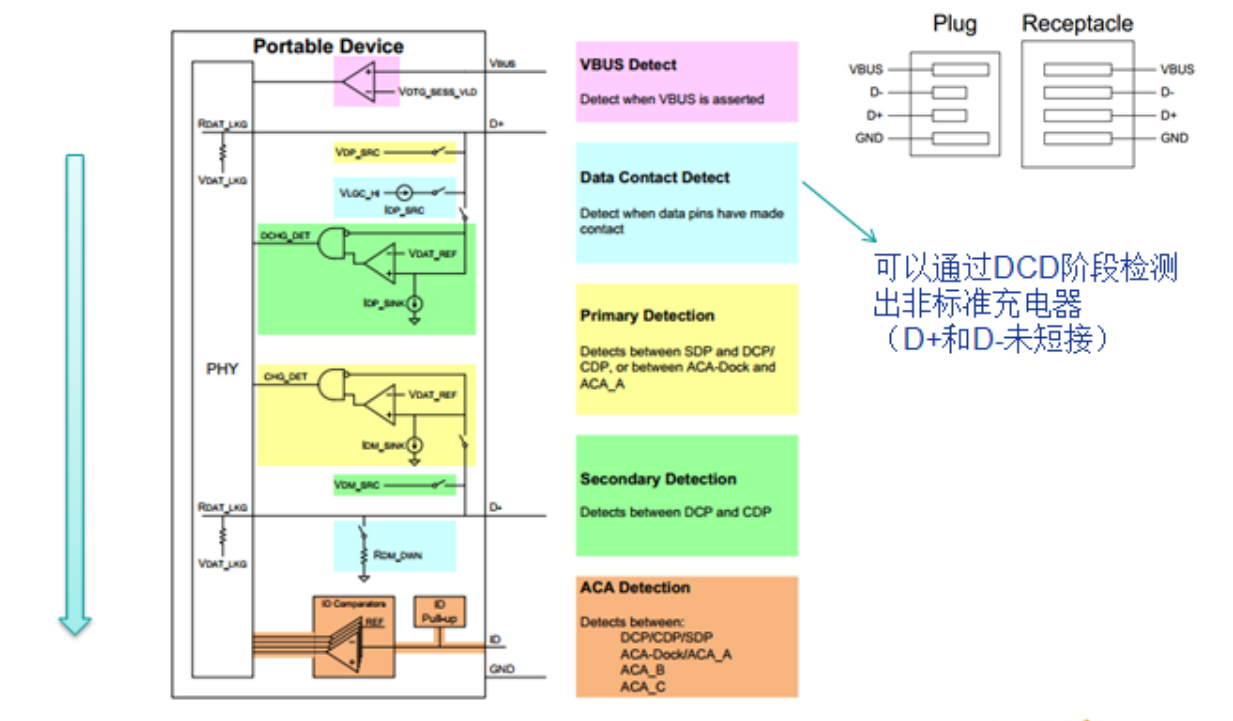
Figure 8-1 USB Charging Detection Process In the typical SDP detection process, the D+/D- signals is shown as follows:
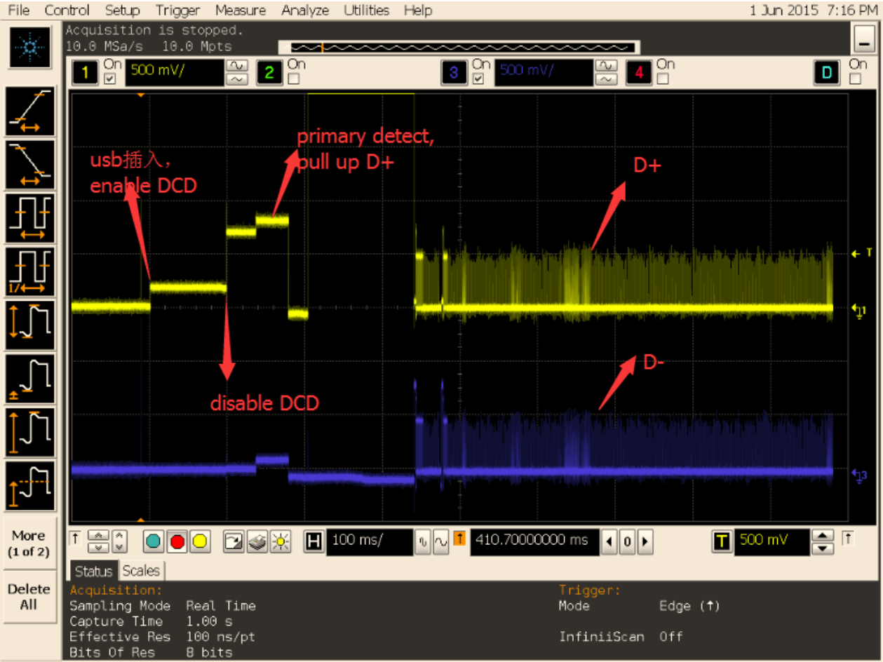
Figure 8-2 SDP detection signals In the typical DCP detection process, the D+/D- signals is shown as follows:
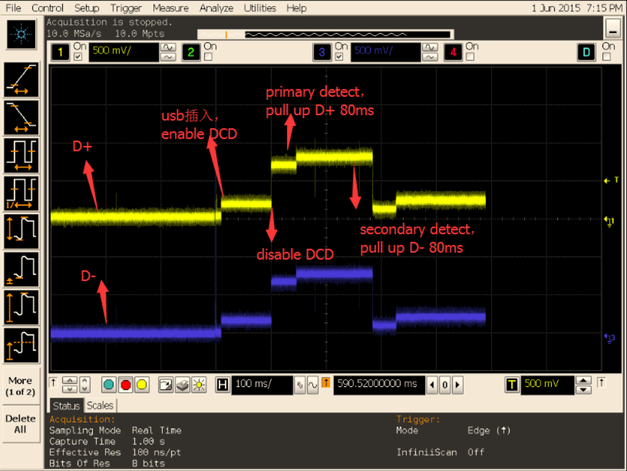
Figure 8-3 DCP detection signals If connected to an USB charger, but it is found that charging is slow, may be the DCP is misdetected as SDP, resulting in charging current set to 500 mA. This problem may happens when the USB cable connection is unstable or the charging detection driver is wrong. Try to fix it step by step:
- Capture the uart log when connected to the USB charger and judge the charging type by the prompt of the log. The normal charging type log should be DCP.
- If the log shows that the charge type is SDP, then an error detection has occurred. First, try to change an USB cable, and test again, if this issue still exits, please use oscilloscope to capture D+/D- signals when USB cable plug in, and send both the error kernel log and D+/D- signals to us.
- If the connection is a USB charger and the logs show it’s DCP, it indicates that the software detects normally, but if the charging is still slow, it may be a problem of charging IC or battery.
8.2.6 USB Transfer Rate Problem
The main factors affecting the transmission rate: USB signal quality USB controller bus frequency
CPU/DDR operating frequency Read and write performance of storage media File system format of storage device USB device class driver Reference: “Rockchip_Developer_Guide_Linux_USB_Performance_Analysis_CN”
8.2.7 USB Enumeration Rate
Pay attention to the printed log of the USB enumeration. “high-speed” means recognized as USB 2.0, and “super-speed” means recognized as USB 3.0.
8.2.8 USB3.0 Recognized Problem
After the USB3.0 device is plugged in, nothing happens, how to troubleshoot? According to the definition of USB3.0 enumeration process, it is generally stuck at the Link Training process of USB 3.0 PHY, that is, the problem of USB PHY signal. You can use the USB3.0 analyzer to capture the Link Training process and combine it with the LTSSM state machine described in the USB 3.0 Spec for analysis.
8.2.9 USB 3.0 Disk Copy Problem
Confirm whether the VBUS supply current meets the requirements On the PC side, perform the same operation for comparison Use USB 3.0 analyzer to capture communication protocol Reduce the size of the data block transmitted once, update the xHCI driver, and open the xHCI debug log
8.2.10 USB3.0 Camera Transmission Problem
It is generally related to the efficiency of USB access to the DDR bus. Optimization means: ddr fixed frequency 800MHz; Improve USB QOS; Optimize the interrupt processing efficiency of uvc driver, put memcpy operation in the lower half; urb buffer uses kmalloc allocation instead of the default dma_alloc_coherent method; If the RK platform is for UVC Gadget, you can dynamically allocate TxFIFO to increase the size of TxFIFO;
8.3 About PC USB Driver
The developers often use USB download mode (rockusb) and USB debug mode (ADB) on Rockchip platforms during development stage.
- PC Windows USB Driver Need to install Rockchip vendor special USB driver in Windows. Rockchip provides a tool “DriverAssitant” for you to install Rockchip vendor special USB driver.
- PC Ubuntu USB Driver No need to install vendor special USB driver.
9. USB Signal Quality Test
Refer to the document “Rockchip_Developer_Guide_USB_SQ_Test_CN” and “Rockchip_Introduction_USB_SQ_Tool_CN”. Rockchip USB SQ Tool: https://redmine.rockchip.com.cn/documents/113
Chinese V2.4.0 technical additions and source differences
The controller table differs: RK3288 EHCI/OHCI is 1 in Chinese and 0 in English. The Chinese xHCI aggregate bandwidth is 8Gbps versus 8.48Gbps in English; the Chinese Device endpoint statement requires the chip manual, whereas English lists 7 IN / 6 OUT / 13 resources. These are unresolved source differences, not verified hardware limits. Chinese §1.6 restricts the described Type-C PHY to RK3399/RK3399Pro. English §1.3 additionally describes packet-based dynamic FIFO allocation. Do not extrapolate any example to all ArmSoM boards.
VID/PID and programming tools
Chinese §6.3 explicitly limits use of Rockchip VID 0x2207 to product development/debugging. A product seeking USB-IF certification must obtain its own authorized unique vendor ID through USB-IF membership. Maskrom/Loader Rockusb PID and Google Accessory VID/PID must not be changed. For custom PID, the source recommends zero upper 8 bits and avoiding the usual PIDs below so Rockchip programming tools do not misidentify devices; this normally does not affect PC driver loading or USB application functionality. The English older table gives ACCESSORY PID 0x18d1, while the Chinese table gives 0x2d00; both source values remain visible. The detailed Chinese table and programming-tool table follow.
Rockchip programming tools identify device function by VID/PID and may perform actions such as mode switching. On Windows, config.ini permits adding custom VID/PID; follow its configuration instructions.
Additional debugging interfaces from Chinese §7.1
Replace [usb controller name] with the actual chip Device controller name. Disconnect and reconnect Gadget with soft_connect; current_speed shows negotiated speed, and state shows states such as not attached/configured:
echo disconnect > /sys/class/udc/[usb controller name]/soft_connect
echo connect > /sys/class/udc/[usb controller name]/soft_connect
cat /sys/class/udc/[usb controller name]/current_speed
cat /sys/class/udc/[usb controller name]/state
Each usb* node under /sys/bus/usb/drivers/usb represents one Host controller. Its bind/unbind interface reinitializes it and reenumerates attached peripherals. Gadget controllers similarly expose /sys/bus/platform/drivers/[usb controller name]/bind and unbind; the Chinese RV1126 UVC recovery sequence is preserved in the source-code supplement below. The chapter also links USB SQ Tool at https://redmine.rockchip.com.cn/documents/109; the English final chapter instead links /documents/113. These distinct source links are retained.
Additional fault analysis from Chinese §8.2
When several controllers share a physical port, or one controller serves several ports, electronic switches may route signals and power. Controller power controls must remain independent and the switched connection must be valid. Scenario 1: one physical port uses USB 2.0 Host for Host and USB 2.0 OTG for Device. In Host, route signals to the Host controller and use its VBUS supply without disturbing Device VBUS detection; in Device, route to OTG and take VBUS from the PC. Scenario 2: one OTG controller serves separate Host and Device ports. In Host route DP/DM to the Host port with 5V/500mA; in Device route DP/DM to the Device port and detect only the PC-supplied 5V.
No Device log: confirm Device mode, circuitry and signals, then verify USB_DET rises low-to-high on insertion. Normal kernel enumeration but no application access: select MTP/PTP, capture logcat, and ask the Android vold/mtpserver maintainer to debug. Copy failures after successful connection: test the eye diagram and capture USB traffic; check Flash/SD timeouts (the source describes reconnection logs about every 10s with Windows XP); check partition errors if failure always occurs at the same copy position. The source proposes chkdsk E: /f for a partition mounted as E:. This modifies the filesystem; it is preserved as source material and was not executed. Persistently high VBUS after unplugging also affects suspend/wakeup and needs hardware investigation.
A functioning Host provides 5V and at least 500mA, then logs standard enumeration. No log: verify switched wiring, Host mode and supply. Enumeration without class-driver logs: enable the required kernel class driver. Complete kernel logs and device nodes but no Android access: Android integration may be incomplete. For storage, vold must mount /dev/block/sda at /udisk for media library/file manager use; HID also requires Android support. Inspect /system/etc/vold.fstab. The source example mount path may actually need the usb20_OTG controller or a usb1 suffix; its original dev_mount command is preserved below. Consult the Android maintainer. transfer_buffer must be four-byte aligned; this also applies to the data argument of usb_control_msg. OTG-as-Host failing detection: check kernel OTG configuration, low ID level and 5V VBUS, then collect failure logs.
For a camera still failing after configuration and boot-time insertion checks, supply logs to the USB/Camera maintainer. Camera hotplug requires Android Camera changes, not USB-driver changes. For charger misdetection, Chinese additionally instructs checking D+/D- shorting with a multimeter after changing the cable. For PC rockusb drivers, Chinese explicitly requires DriverAssitant v4.4 for RK3399; unprogrammed or upgrade-mode chips use rockusb, while a running device with USB debugging enabled uses ADB.
10. USB development resources
Chinese §10 locates USB documents, reference designs and common-problem solutions in Redmine → FAE project → Documents: https://redmine.rockchip.com.cn/documents/113. Access may require an account. This section is absent from the English edition.
Editable transcription of Type-C pinout
| Pin | Signal | Pin | Signal |
|---|---|---|---|
| A1 | GND | B1 | GND |
| A2 | TX1+ | B2 | TX2+ |
| A3 | TX1− | B3 | TX2− |
| A4 | VBUS | B4 | VBUS |
| A5 | CC1 | B5 | CC2 |
| A6 | D+ | B6 | D+ |
| A7 | D− | B7 | D− |
| A8 | SBU1 | B8 | SBU2 |
| A9 | VBUS | B9 | VBUS |
| A10 | RX2− | B10 | RX1− |
| A11 | RX2+ | B11 | RX1+ |
| A12 | GND | B12 | GND |
Alternate-source code differences
The following Chinese-source blocks differ verbatim from the English blocks, including page splits or comment differences. They are alternative original examples, not a single script to execute. Parameters are retained for comparison.
CN · PDF p.25 · #149
Device Drivers  --->
    -*- Support for Host-side USB
CN · PDF p.26 · #150
[*] USB support  --->
    ...
    <*> xHCI HCD (USB 3.0) support
    -*- Generic xHCI driver for a platform device
    ...
    <*> EHCI HCD (USB 2.0) support
    [ ]     Root Hub Transaction Translators
    [*]     Improved Transaction Translator scheduling
    <*> Generic EHCI driver for a platform device
    ...
    <*> OHCI HCD (USB 1.1) support
    < >     OHCI support for PCI-bus USB controllers
    <*>     Generic OHCI driver for a platform device
CN · PDF p.26 · #156
DeviceDrivers  --->
    [*]USB support  --->
        [*] USB Gadget Support  --->
            ...
CN · PDF p.27 · #157
USBGadget Drivers (USB functions configurable through configfs)  --->
    [ ]       Generic serial bulk in/out
    [*]       Abstract Control Model (CDC ACM)
    [ ]       Object Exchange Model (CDC OBEX)
    [ ]       Network Control Model (CDC NCM)
    [ ]       Ethernet Control Model (CDC ECM)
    [ ]       Ethernet Control Model (CDC ECM) subset
    [*]       RNDIS
    [ ]       Ethernet Emulation Model (EEM)
    [*]       Mass storage
    [ ]       Loopback and sourcesink function (for testing)
    [*]       Function filesystem (FunctionFS)
    [*]       MTP gadget
    [*]         PTP gadget
    [*]       Accessory gadget
    [*]         Audio Source gadget
    [*]       Uevent notification of Gadget state
    [ ]       Audio Class 1.0
    [ ]       Audio Class 2.0
    [*]       MIDI function
    [ ]       HID function
    [ ]       USB Webcam function
    [ ]       Printer function
CN · PDF p.27 · #162
Device Drivers --->
    SCSI device support --->
        <*> SCSI device support
        [ ] SCSI: use blk-mq I/O path by default
        [*] legacy /proc/scsi/ support
            *** SCSI support type (disk, tape, CD-ROM) ***
        <*> SCSI disk support
        < > SCSI tape support
        < > SCSI OnStream SC-x0 tape support
        < > SCSI CDROM support
        <*> SCSI generic support
        <*> SCSI media changer support
        [*] Verbose SCSI error reporting (kernel size +=75K)
        [*] SCSI logging facility
CN · PDF p.28 · #163
[*] Asynchronous SCSI scanning
    SCSI Transports  --->
[*] SCSI low-level drivers  --->
[ ] PCMCIA SCSI adapter support  ----
[ ] SCSI Device Handlers  ----
CN · PDF p.28 · #170
Device Driver --->
    [*] Network device support  --->
        <*>   PPP (point-to-point protocol) support
            <*>     PPP BSD-Compress compression
            <*>     PPP Deflate compression
            [*]     PPP filtering
            <*>     PPP MPPE compression (encryption)
            [*]     PPP multilink support
            <*>     PPP over Ethernet
            <*>     PPP over L2TP
            <*>     PPP on L2TP Access Concentrator
            <*>     PPP on PPTP Network Server
            <*>     PPP support for async serial ports
            <*>     PPP support for sync tty ports
CN · PDF p.30 · #183
Device Driver --->
    [*] Network device support  --->
        <*> USB Network Adapters  --->
            <*> USB CATC NetMate-based Ethernet device support
            <*> USB KLSI KL5USB101-based ethernet device support
            <*> USB Pegasus/Pegasus-II based ethernet device support
            <*> USB RTL8150 based ethernet device support
            <*> Realtek RTL8152/RTL8153 Based USB Ethernet Adapters
            < > Microchip LAN78XX Based USB Ethernet Adapters
            <*> Multi-purpose USB Networking Framework
            <*>     ASIX AX88xxx Based USB 2.0 Ethernet Adapters
            <*>     ASIX AX88179/178A USB 3.0/2.0 to Gigabit Ethernet
            -*- CDC Ethernet support (smart devices such as cable modems)
            <*> CDC EEM support
            -*- CDC NCM support
            < > Huawei NCM embedded AT channel support
            <*> CDC MBIM support
            <*> Davicom DM96xx based USB 10/100 ethernet devices
            < > CoreChip-sz SR9700 based USB 1.1 10/100 ethernet devices
            < > CoreChip-sz SR9800 based USB 2.0 10/100 ethernet devices
            <*> SMSC LAN75XX based USB 2.0 gigabit ethernet devices
            <*> SMSC LAN95XX based USB 2.0 10/100 ethernet devices
            <*> GeneSys GL620USB-A based cables
            <*> NetChip 1080 based cables (Laplink, ...)
            <*> Prolific PL-2301/2302/25A1/27A1 based cables
            <*> MosChip MCS7830 based Ethernet adapters
            <*> Host for RNDIS and ActiveSync devices
            <*> Simple USB Network Links (CDC Ethernet subset)
            [*]     ALi M5632 based 'USB 2.0 Data Link' cables
            [*]     AnchorChips 2720 based cables (Xircom PGUNET, ...)
            [*]     eTEK based host-to-host cables (Advance, Belkin, ...)
            [*]     Embedded ARM Linux links (iPaq, ...)
            [*]     Epson 2888 based firmware (DEVELOPMENT)
            [*]     KT Technology KC2190 based cables (InstaNet)
            <*> Sharp Zaurus (stock ROMs) and compatible
            <*> Conexant CX82310 USB ethernet port
            <*> Samsung Kalmia based LTE USB modem
            <*> QMI WWAN driver for Qualcomm MSM based 3G and LTE modems
            <*> Option USB High Speed Mobile Devices
            <*> Intellon PLC based usb adapter
            <*> Apple iPhone USB Ethernet driver
            <*> USB-to-WWAN Driver for Sierra Wireless modems
            < > LG VL600 modem dongle
            < > QingHeng CH9200 USB ethernet support
CN · PDF p.31 · #190
Device Drivers --->
    [*] USB support --->
        -*- Support for Host-side USB
        ...
        [*]     Disable external hubs
CN · PDF p.32 · #199
grf: syscon@ff770000 {
    compatible = "rockchip,rk3399-grf", "syscon", "simple-mfd";
    reg = <0x0 0xff770000 0x0 0x10000>;
    #address-cells = <1>;
    #size-cells = <1>;

    u2phy0: usb2-phy@e450 {
        compatible = "rockchip,rk3399-usb2phy";
CN · PDF p.33 · #200
        reg = <0xe450 0x10>;
        clocks = <&cru SCLK_USB2PHY0_REF>;
        clock-names = "phyclk";
        #clock-cells = <0>;
        clock-output-names = "clk_usbphy0_480m";
        status = "disabled";

        u2phy0_host: host-port {
            #phy-cells = <0>;
            interrupts = <GIC_SPI 27 IRQ_TYPE_LEVEL_HIGH 0>;
            interrupt-names = "linestate";
            status = "disabled";
        };

        u2phy0_otg: otg-port {
            #phy-cells = <0>;
            interrupts = <GIC_SPI 103 IRQ_TYPE_LEVEL_HIGH 0>,
                         <GIC_SPI 104 IRQ_TYPE_LEVEL_HIGH 0>,
                         <GIC_SPI 106 IRQ_TYPE_LEVEL_HIGH 0>;
            interrupt-names = "otg-bvalid", "otg-id",
                              "linestate";
            status = "disabled";
        };
    };
};
CN · PDF p.33 · #202
vcc5v0_host: vcc5v0-host-regulator {
    compatible = "regulator-fixed";
    enable-active-high;
    gpio = <&gpio4 25 GPIO_ACTIVE_HIGH>;
    pinctrl-names = "default";
    pinctrl-0 = <&host_vbus_drv>;
    regulator-name = "vcc5v0_host";
    regulator-always-on;
};

usb2 {
    host_vbus_drv: host-vbus-drv {
        rockchip,pins =
                <4 25 RK_FUNC_GPIO &pcfg_pull_none>;
    };
};
CN · PDF p.34 · #209
tcphy0: phy@ff7c0000 {
    compatible = "rockchip,rk3399-typec-phy";
    reg = <0x0 0xff7c0000 0x0 0x40000>;
    rockchip,grf = <&grf>;
    #phy-cells = <1>;
CN · PDF p.35 · #210
    clocks = <&cru SCLK_UPHY0_TCPDCORE>,
             <&cru SCLK_UPHY0_TCPDPHY_REF>;
    clock-names = "tcpdcore", "tcpdphy-ref";
    assigned-clocks = <&cru SCLK_UPHY0_TCPDCORE>;
    assigned-clock-rates = <50000000>;
    power-domains = <&power RK3399_PD_TCPD0>;
    resets = <&cru SRST_UPHY0>,
             <&cru SRST_UPHY0_PIPE_L00>,
             <&cru SRST_P_UPHY0_TCPHY>;
    reset-names = "uphy", "uphy-pipe", "uphy-tcphy";
    rockchip,typec-conn-dir = <0xe580 0 16>;
    rockchip,usb3tousb2-en = <0xe580 3 19>;
    rockchip,usb3-host-disable = <0x2434 0 16>;
    rockchip,usb3-host-port = <0x2434 12 28>;
    rockchip,external-psm = <0xe588 14 30>;
    rockchip,pipe-status = <0xe5c0 0 0>;
    rockchip,uphy-dp-sel = <0x6268 19 19>;
    status = "disabled";

    tcphy0_dp: dp-port {
        #phy-cells = <0>;
    };

    tcphy0_usb3: usb3-port {
        #phy-cells = <0>;
    };
};
CN · PDF p.37 · #226
usb20_otg: usb@ff580000 {
    compatible = "rockchip,rk3328-usb", "rockchip,rk3066-usb",
                 "snps,dwc2";
    reg = <0x0 0xff580000 0x0 0x40000>;
    interrupts = <GIC_SPI 23 IRQ_TYPE_LEVEL_HIGH>;
    clocks = <&cru HCLK_OTG>, <&cru HCLK_OTG_PMU>;
    clock-names = "otg", "otg_pmu";
    dr_mode = "otg";
    g-np-tx-fifo-size = <16>;
    g-rx-fifo-size = <275>;
    g-tx-fifo-size = <256 128 128 64 64 32>;
    g-use-dma;
    phys = <&u2phy_otg>;
    phy-names = "usb2-phy";
    status = "disabled";
};
CN · PDF p.38 · #233
usbdrd3_0: usb0 {
        compatible = "rockchip,rk3399-dwc3";
        clocks = <&cru SCLK_USB3OTG0_REF>, <&cru SCLK_USB3OTG0_SUSPEND>,
CN · PDF p.39 · #234
         <&cru ACLK_USB3OTG0>, <&cru ACLK_USB3_GRF>;
    clock-names = "ref_clk", "suspend_clk",
              "bus_clk", "grf_clk";
    power-domains = <&power RK3399_PD_USB3>;
    resets = <&cru SRST_A_USB3_OTG0>;
    reset-names = "usb3-otg";
    #address-cells = <2>;
    #size-cells = <2>;
    ranges;
    status = "disabled";

    usbdrd_dwc3_0: dwc3@fe800000 {
        compatible = "snps,dwc3";
        reg = <0x0 0xfe800000 0x0 0x100000>;
        interrupts = <GIC_SPI 105 IRQ_TYPE_LEVEL_HIGH 0>;
        dr_mode = "otg";
        phys = <&u2phy0_otg>, <&tcphy0_usb3>;
        phy-names = "usb2-phy", "usb3-phy";
        phy_type = "utmi_wide";
        snps,dis_enblslpm_quirk;
        snps,dis-u2-freeclk-exists-quirk;
        snps,dis_u2_susphy_quirk;
        snps,dis-del-phy-power-chg-quirk;
        snps,tx-ipgap-linecheck-dis-quirk;
        snps,xhci-slow-suspend-quirk;
        snps,xhci-trb-ent-quirk;
        snps,usb3-warm-reset-on-resume-quirk;
        status = "disabled";
    };
};
CN · PDF p.39 · #239
extcon_usb: extcon-usb {
        compatible = "linux,extcon-usb-gpio";
        /* 硬件设计对电平做了反向处理,这⾥必须配置为 GPIO_ACTIVE_LOW */
        vbus-gpio = <&gpio1 RK_PC5 GPIO_ACTIVE_LOW>;
        pinctrl-names = "default";
CN · PDF p.40 · #240
        pinctrl-0 = <&usb_extcon_vbus>;
        status = "okay";
};

&pinctrl {
        usb {
                usb_extcon_vbus: usb-extcon-vbus {
                rockchip,pins = <1 RK_PC5 RK_FUNC_GPIO &pcfg_pull_none>;
            };
        };
};

&u2phy_otg0 {
        /* 添加属性 rockchip,gpio-vbus-det,表⽰ phy 驱动⽀持 VBUS GPIO 检测⽅式 */
        rockchip,gpio-vbus-det;
        status = "okay";
};

&usb2phy {
        extcon = <&extcon_usb>;
        status = "okay";
};
CN · PDF p.40 · #245
extcon_usb: extcon-usb {
        compatible = "linux,extcon-usb-gpio";
        id-gpio = <&gpio3 RK_PB4 GPIO_ACTIVE_HIGH>;
        /* 注意 pinctrl-names 要设置为 default, 否则 pinctrl 节点的 pcfg_pull_up 配置会不⽣效 */
        pinctrl-names = "default";
        pinctrl-0 = <&usb_extcon_id>;
        status = "okay";
};

&pinctrl {
        usb {
                usb_extcon_id: usb-extcon-id {
CN · PDF p.41 · #246
                        /* ID 默认要内部拉⾼,配置为 pcfg_pull_up */
                        rockchip,pins = <3 RK_PB4 RK_FUNC_GPIO &pcfg_pull_up>;
                };
        };
};

&u2phy_otg0 {
        rockchip,gpio-id-det;
        status = "okay";
};

&usb2phy {
        extcon = <&extcon_usb>;
        status = "okay";
};
CN · PDF p.41 · #249
extcon_usb: extcon-usb {
        compatible = "linux,extcon-usb-gpio";
        vbus-gpio = <&gpio3 RK_PB2 GPIO_ACTIVE_LOW>;
        id-gpio = <&gpio3 RK_PB4 GPIO_ACTIVE_HIGH>;
        /* 注意 pinctrl-names 要设置为 default, 否则 pinctrl 节点的 pcfg_pull_up 配置会不⽣效 */
        pinctrl-names = "default";
        /* 注意 pinctrl-0 同时引⽤ usb_extcon_vbus 和 usb_extcon_id */
        pinctrl-0 = <&usb_extcon_vbus &usb_extcon_id>;
        status = "okay";
};

&pinctrl {
        usb {
                usb_extcon_id: usb-extcon-id {
                        rockchip,pins = <3 RK_PB4 RK_FUNC_GPIO &pcfg_pull_up>;
                };

                usb_extcon_vbus: usb-extcon-vbus {
                        rockchip,pins = <3 RK_PB2 RK_FUNC_GPIO &pcfg_pull_none>;
                };
        };
};

&u2phy_otg0 {
        rockchip,gpio-vbus-det;
        rockchip,gpio-id-det;
        status = "okay";
};

&usb2phy {
CN · PDF p.42 · #250
        extcon = <&extcon_usb>;
        status = "okay";
};
CN · PDF p.45 · #268
static const struct rockchip_usb2phy_cfg rk3399_phy_cfgs[] = {
        {
                .reg            = 0xe450,
                .num_ports      = 2,
                .phy_tuning     = rk3399_usb2phy_tuning,
                .clkout_ctl     = { 0xe450, 4, 4, 1, 0 },
                .port_cfgs      = {
                        [USB2PHY_PORT_OTG] = {
                                .phy_sus = { 0xe454, 8, 0, 0x052, 0x1d1 },
                                .bvalid_det_en  = { 0xe3c0, 3, 3, 0, 1 },
                                .bvalid_det_st  = { 0xe3e0, 3, 3, 0, 1 },
                                .bvalid_det_clr = { 0xe3d0, 3, 3, 0, 1 },
                                .bypass_dm_en   = { 0xe450, 2, 2, 0, 1 },
                                .bypass_sel     = { 0xe450, 3, 3, 0, 1 },
                                .idfall_det_en  = { 0xe3c0, 5, 5, 0, 1 },
                                .idfall_det_st  = { 0xe3e0, 5, 5, 0, 1 },
                                .idfall_det_clr = { 0xe3d0, 5, 5, 0, 1 },
                                .idrise_det_en  = { 0xe3c0, 4, 4, 0, 1 },
                                .idrise_det_st  = { 0xe3e0, 4, 4, 0, 1 },
                                .idrise_det_clr = { 0xe3d0, 4, 4, 0, 1 },
                                .ls_det_en      = { 0xe3c0, 2, 2, 0, 1 },
                                .ls_det_st      = { 0xe3e0, 2, 2, 0, 1 },
                                .ls_det_clr     = { 0xe3d0, 2, 2, 0, 1 },
                                .utmi_avalid    = { 0xe2ac, 7, 7, 0, 1 },
                                .utmi_bvalid    = { 0xe2ac, 12, 12, 0, 1 },
                                .utmi_iddig     = { 0xe2ac, 8, 8, 0, 1 },
                                .utmi_ls        = { 0xe2ac, 14, 13, 0, 1 },
                                .vbus_det_en    = { 0x449c, 15, 15, 1, 0 },
                        },
                        [USB2PHY_PORT_HOST] = {
                                .phy_sus        = { 0xe458, 1, 0, 0x2, 0x1 },
                                .ls_det_en      = { 0xe3c0, 6, 6, 0, 1 },
                                .ls_det_st      = { 0xe3e0, 6, 6, 0, 1 },
                                .ls_det_clr     = { 0xe3d0, 6, 6, 0, 1 },
                                .utmi_ls        = { 0xe2ac, 22, 21, 0, 1 },
                                .utmi_hstdet    = { 0xe2ac, 23, 23, 0, 1 }
                        }
CN · PDF p.46 · #269
        },
        .chg_det = {
                .opmode         = { 0xe454, 3, 0, 5, 1 },
                .cp_det         = { 0xe2ac, 2, 2, 0, 1 },
                .dcp_det        = { 0xe2ac, 1, 1, 0, 1 },
                .dp_det         = { 0xe2ac, 0, 0, 0, 1 },
                .idm_sink_en    = { 0xe450, 8, 8, 0, 1 },
                .idp_sink_en    = { 0xe450, 7, 7, 0, 1 },
                .idp_src_en     = { 0xe450, 9, 9, 0, 1 },
                .rdm_pdwn_en    = { 0xe450, 10, 10, 0, 1 },
                .vdm_src_en     = { 0xe450, 12, 12, 0, 1 },
                .vdp_src_en     = { 0xe450, 11, 11, 0, 1 },
        },
},
{
        .reg            = 0xe460,
        .num_ports      = 2,
        .phy_tuning     = rk3399_usb2phy_tuning,
        .clkout_ctl     = { 0xe460, 4, 4, 1, 0 },
        .port_cfgs      = {
                [USB2PHY_PORT_OTG] = {
                        .phy_sus = { 0xe464, 8, 0, 0x052, 0x1d1 },
                        .bvalid_det_en  = { 0xe3c0, 8, 8, 0, 1 },
                        .bvalid_det_st  = { 0xe3e0, 8, 8, 0, 1 },
                        .bvalid_det_clr = { 0xe3d0, 8, 8, 0, 1 },
                        .idfall_det_en  = { 0xe3c0, 10, 10, 0, 1 },
                        .idfall_det_st  = { 0xe3e0, 10, 10, 0, 1 },
                        .idfall_det_clr = { 0xe3d0, 10, 10, 0, 1 },
                        .idrise_det_en  = { 0xe3c0, 9, 9, 0, 1 },
                        .idrise_det_st  = { 0xe3e0, 9, 9, 0, 1 },
                        .idrise_det_clr = { 0xe3d0, 9, 9, 0, 1 },
                        .ls_det_en      = { 0xe3c0, 7, 7, 0, 1 },
                        .ls_det_st      = { 0xe3e0, 7, 7, 0, 1 },
                        .ls_det_clr     = { 0xe3d0, 7, 7, 0, 1 },
                        .utmi_avalid    = { 0xe2ac, 10, 10, 0, 1 },
                        .utmi_bvalid    = { 0xe2ac, 16, 16, 0, 1 },
                        .utmi_iddig     = { 0xe2ac, 11, 11, 0, 1 },
                        .utmi_ls        = { 0xe2ac, 18, 17, 0, 1 },
                        .vbus_det_en    = { 0x451c, 15, 15, 1, 0 },
                },
                [USB2PHY_PORT_HOST] = {
                        .phy_sus        = { 0xe468, 1, 0, 0x2, 0x1 },
                        .ls_det_en      = { 0xe3c0, 11, 11, 0, 1 },
                        .ls_det_st      = { 0xe3e0, 11, 11, 0, 1 },
                        .ls_det_clr     = { 0xe3d0, 11, 11, 0, 1 },
                        .utmi_ls        = { 0xe2ac, 26, 25, 0, 1 },
                        .utmi_hstdet    = { 0xe2ac, 27, 27, 0, 1 }
                }
        },
        .chg_det = {
                .opmode         = { 0xe464, 3, 0, 5, 1 },
                .cp_det         = { 0xe2ac, 5, 5, 0, 1 },
                .dcp_det        = { 0xe2ac, 4, 4, 0, 1 },
CN · PDF p.47 · #270
                        .dp_det         = { 0xe2ac, 3, 3, 0, 1 },
                        .idm_sink_en    = { 0xe460, 8, 8, 0, 1 },
                        .idp_sink_en    = { 0xe460, 7, 7, 0, 1 },
                        .idp_src_en     = { 0xe460, 9, 9, 0, 1 },
                        .rdm_pdwn_en    = { 0xe460, 10, 10, 0, 1 },
                        .vdm_src_en     = { 0xe460, 12, 12, 0, 1 },
                        .vdp_src_en     = { 0xe460, 11, 11, 0, 1 },
                },
        },
        { /* sentinel */ }
};
CN · PDF p.54 · #301
~/src/android_Q/kernel/drivers/usb/dwc2$ tree
.
├── core.c        (dwc2 core reset, 配置 core param等通⽤操作)
├── core.h
├── core_intr.c   (dwc2 通⽤中断事件,包括otg intr,id intr,wakeup intr等)
├── debugfs.c     (dwc2 调试接⼝,⽐如打印寄存器信息)
├── debug.h
├── gadget.c      (dwc2 gadget mode相关的所有任务,如 gadget 初始化,gadget 中断事件)
├── hcd.c         (dwc2 host mode相关任务以及core init,phy init,device/host mode切换)
├── hcd_ddma.c    (dwc2 descriptor DMA相关的任务)
├── hcd.h
├── hcd_intr.c    (dwc2 host mode的所有中断事件处理)
├── hcd_queue.c   (dwc2 host mode的传输队列处理)
├── hw.h
├── Kconfig
├── Makefile
├── pci.c         (pci 总线接⼝的初始化,Rockchip dwc2使⽤ AHB 总线)
└── platform.c    (实现dwc2 probe,根据不同芯⽚的core_params配置,初始化dwc2 lowlevel hw
resources)
CN · PDF p.54 · #306
rk3288:/sys/devices/platform/ff580000.usb # ls
busconnected  fr_interval gsnpsid   modalias       regoffset     uevent
buspower      gadget      guid      mode           regvalue      usb5
bussuspend    ggpio       gusbcfg   mode_ch_tim_en remote_wakeup wr_reg_test
CN · PDF p.55 · #307
devspeed      gnptxfsiz   hcd_frrem pools          spramdump
disconnect_us gotgctl     hcddump   power          subsystem
driver        gpvndctl    hprt0     rd_reg_test    test_sq
enumspeed     grxfsiz     hptxfsiz  regdump        udc

rk3288:/sys/devices/platform/ff580000.usb/driver # ls
bind       dwc_otg_conn_en force_usb_mode uevent vbus_status
debuglevel ff580000.usb    op_state       unbind versio
CN · PDF p.56 · #317
~/src/android_Q/kernel/drivers/usb/host$ tree
├── ehci-dbg.c      (ehci debugfs调试接⼝,如打印 ehci 寄存器信息)
├── ehci.h
├── ehci-hcd.c      (ehci 控制器的初始化,中断事件处理,urb 队列的管理等)
├── ehci-hub.c      (ehci root hub 的控制和状态查询,bus suspend/resume)
├── ehci-mem.c      (ehci mem 的分配和初始化,qtd/qh资源的分配和初始化)
├── ehci-pci.c      (pci 总线接⼝的初始化,Rockchip ehci使⽤ AHB 总线,不使⽤该驱动)
├── ehci-platform.c (ehci 通⽤平台驱动,实现ehci probe,向usb bus注册ehci hcd,使能ehci控制器)
├── ehci-q.c        (ehci qtd/qh传输队列的处理)
├── ehci-sched.c    (ehci interrupt, iso, split iso的周期传输调度处理)
├── ehci-sysfs.c    (ehci sysfs调试接⼝,显⽰ companion 控制器,显⽰ uframe_periodic_max)
├── ehci-timer.c    (ehci timer相关的任务处理)
CN · PDF p.56 · #319
static const struct hc_driver ehci_hc_driver = {
    .description =      hcd_name,
    .product_desc =     "EHCI Host Controller",
    .hcd_priv_size =    sizeof(struct ehci_hcd),
    /*
     * generic hardware linkage
     */
    .irq =          ehci_irq,
    .flags =        HCD_MEMORY | HCD_USB2 | HCD_BH,
    /*
     * basic lifecycle operations
     */
    .reset =        ehci_setup,
    .start =        ehci_run,
    .stop =         ehci_stop,
    .shutdown =     ehci_shutdown,
    /*
     * managing i/o requests and associated device resources
     */
    .urb_enqueue =      ehci_urb_enqueue,
CN · PDF p.57 · #320
    .urb_dequeue =      ehci_urb_dequeue,
    .endpoint_disable = ehci_endpoint_disable,
    .endpoint_reset =   ehci_endpoint_reset,
    .clear_tt_buffer_complete = ehci_clear_tt_buffer_complete,
    /*
     * scheduling support
     */
    .get_frame_number = ehci_get_frame,
    /*
     * root hub support
     */
    .hub_status_data =  ehci_hub_status_data,
    .hub_control =      ehci_hub_control,
    .bus_suspend =      ehci_bus_suspend,
    .bus_resume =       ehci_bus_resume,
    .relinquish_port =  ehci_relinquish_port,
    .port_handed_over = ehci_port_handed_over,
    /*
     * device support
     */
    .free_dev =     ehci_remove_device,
};
CN · PDF p.57 · #322
~/src/android_Q/kernel/drivers/usb/host$ tree
├── ohci-dbg.c     (ohci debugfs调试接⼝,如打印 ohci 寄存器信息)
├── ohci.h
├── ohci-hcd.c     (ohci 控制器的初始化,中断事件处理,urb 队列的管理等)
├── ohci-hub.c     (ohci root hub 的控制和状态查询,bus suspend/resume)
├── ohci-mem.c     (ohci mem 的分配和初始化,td/ed资源的分配和初始化)
├── ohci-pci.c     (pci 总线接⼝的初始化,Rockchip ohci使⽤ AHB 总线,不使⽤该驱动⽂件)
├── ohci-platform.c(ohci 通⽤平台驱动,实现ohci probe,向usb bus注册ohci hcd,使能ohci控制器)
├── ohci-q.c       (ohci td/ed传输队列的处理)
CN · PDF p.57 · #324
static const struct hc_driver ohci_hc_driver = {
    .description =          hcd_name,
    .product_desc =         "OHCI Host Controller",
    .hcd_priv_size =        sizeof(struct ohci_hcd),
    /*
     * generic hardware linkage
    */
    .irq =                  ohci_irq,
    .flags =                HCD_MEMORY | HCD_USB11,
CN · PDF p.58 · #325
    /*
    * basic lifecycle operations
    */
    .reset =                ohci_setup,
    .start =                ohci_start,
    .stop =                 ohci_stop,
    .shutdown =             ohci_shutdown,
    /*
     * managing i/o requests and associated device resources
    */
    .urb_enqueue =          ohci_urb_enqueue,
    .urb_dequeue =          ohci_urb_dequeue,
    .endpoint_disable =     ohci_endpoint_disable,
    /*
    * scheduling support
    */
    .get_frame_number =     ohci_get_frame,
    /*
    * root hub support
    */
    .hub_status_data =      ohci_hub_status_data,
    .hub_control =          ohci_hub_control,
#ifdef CONFIG_PM
    .bus_suspend =          ohci_bus_suspend,
    .bus_resume =           ohci_bus_resume,
#endif
    .start_port_reset = ohci_start_port_reset,
};
CN · PDF p.58 · #328
rk3399:/sys/kernel/debug/fe380000.usb # ls
async bandwidth periodic registers

rk3399:/sys/devices/platform/fe380000.usb # ls
companion driver_override of_node power     uevent              usb5
driver    modalias        pools   subsystem uframe_periodic_max usbmon
CN · PDF p.59 · #331
rk3399:/sys/kernel/debug/usb/ohci/fe3a0000.usb # ls
async periodic registers
CN · PDF p.60 · #342
~/src/kernel-4.19/drivers/usb/dwc3$ tree
.
├── core.c              (dwc3 core probe的实现,分配各种资源,初始化控制器,PM runtime 管理)
├── core.h
├── debugfs.c           (dwc3 debugfs调试接⼝的实现)
├── debug.h
├── drd.c               (dwc3 dule role mode/otg mode 动态切换的处理)
├── dwc3-of-simple.c    (dwc3 通⽤平台驱动,实现dwc3的第⼀级dwc3_of_simple_probe,并通过
of_platform_populate 调⽤dwc3 core的第⼆级dwc3_probe)
├── dwc3-pci.c          (pci 总线接⼝的初始化,Rockchip dwc3使⽤AXI总线,不使⽤该驱动⽂件)
├── dwc3-rockchip-inno.c(RK3328/RK3228H专⽤的glue layer,增加了disconnect work的实现)
├── ep0.c               (dwc3 gadget ep0的任务处理)
├── gadget.c            (dwc3 gadget 除ep0外的端点任务处理,中断的⼊⼝函数实现)
├── gadget.h
├── host.c              (dwc3 host资源分配,并通过platform_device_add调⽤xHCI的xhci_plat_probe)
├── io.h
├── Kconfig
CN · PDF p.61 · #343
├── Makefile
├── trace.c              (dwc3 trace的实现,基于linux的trace接⼝)
├── trace.h
└── ulpi.c               (ulpi phy接⼝的代码实现,Rockchip dwc3不使⽤ulpi)

~/src/kernel-4.19/drivers/usb/host$ tree
├── xhci.c               (初始化xhci_hc_driver,启动xHCI控制器,管理urb队列等)
├── xhci-dbg.c           (实现打印log的调试函数)
├── xhci-dbgcap.c        (xHCI 硬件模块 debug capability的功能实现,Rockchip 不⽀持)
├── xhci-dbgcap.h
├── xhci-debugfs.c       (xHCI debugfs调试接⼝)
├── xhci-debugfs.h
├── xhci-ext-caps.c      (xHCI extended capability的功能实现,Rockchip 不⽀持)
├── xhci-ext-caps.h
├── xhci.h
├── xhci-hub.c           (xHCI root hub 的控制和状态查询,bus suspend/resume)
├── xhci-mem.c           (xHCI mem 管理,包括分配,初始化,释放等操作)
├── xhci-pci.c           (pci 总线接⼝的初始化,Rockchip xHCI使⽤AXI总线,不使⽤该驱动⽂件)
├── xhci-plat.c          (xHCI 通⽤平台驱动,实现xhci_plat_probe,Rockchip 使⽤该驱动)
├── xhci-plat.h
├── xhci-ring.c          (xHCI transfer/command/event ring 的管理)
├── xhci-trace.c         (xHCI trace的实现,基于linux的trace接⼝)
└── xhci-trace.h
CN · PDF p.61 · #347
static const struct hc_driver xhci_hc_driver = {
    .description =      "xhci-hcd",
    .product_desc =     "xHCI Host Controller",
    .hcd_priv_size =    sizeof(struct xhci_hcd *),
    /*
     * generic hardware linkage
     */
    .irq =          xhci_irq,
    .flags =        HCD_MEMORY | HCD_USB3 | HCD_SHARED,
    /*
     * basic lifecycle operations
CN · PDF p.62 · #348
     */
    .reset =        NULL, /* set in xhci_init_driver() */
    .start =        xhci_run,
    .stop =         xhci_stop,
    .shutdown =     xhci_shutdown,
    /*
     * managing i/o requests and associated device resources
     */
    .urb_enqueue =      xhci_urb_enqueue,
    .urb_dequeue =      xhci_urb_dequeue,
    .alloc_dev =        xhci_alloc_dev,
    .free_dev =     xhci_free_dev,
    .alloc_streams =    xhci_alloc_streams,
    .free_streams =     xhci_free_streams,
    .add_endpoint =     xhci_add_endpoint,
    .drop_endpoint =    xhci_drop_endpoint,
    .endpoint_reset =   xhci_endpoint_reset,
    .check_bandwidth =  xhci_check_bandwidth,
    .reset_bandwidth =  xhci_reset_bandwidth,
    .address_device =   xhci_address_device,
    .enable_device =    xhci_enable_device,
    .update_hub_device =    xhci_update_hub_device,
    .reset_device =     xhci_discover_or_reset_device,
    /*
     * scheduling support
     */
    .get_frame_number = xhci_get_frame,
    /*
     * root hub support
     */
    .hub_control =      xhci_hub_control,
    .hub_status_data =  xhci_hub_status_data,
    .bus_suspend =      xhci_bus_suspend,
    .bus_resume =       xhci_bus_resume,
    /*
     * call back when device connected and addressed
     */
    .update_device =        xhci_update_device,
    .set_usb2_hw_lpm =  xhci_set_usb2_hardware_lpm,
    .enable_usb3_lpm_timeout =  xhci_enable_usb3_lpm_timeout,
    .disable_usb3_lpm_timeout = xhci_disable_usb3_lpm_timeout,
    .find_raw_port_number = xhci_find_raw_port_number,
};
CN · PDF p.63 · #351
console:/sys/kernel/debug/fe800000.dwc3 # ls
ep0in  ep1in  ep2in  ep3in  ep4in  ep5in  ep6out     lsp_dump regdump
ep0out ep1out ep2out ep3out ep4out ep5out link_state mode     testmode

console:/sys/kernel/debug/usb/xhci/xhci-hcd.0.auto # ls
command-ring ports          reg-ext-legsup:00   reg-op
devices      reg-cap        reg-ext-protocol:00 reg-runtime
event-ring   reg-ext-dbc:00 reg-ext-protocol:01
CN · PDF p.63 · #353
#RK3399 Type-C0 USB OTG 切换命令
#1.Force host mode
  echo host > sys/kernel/debug/usb@fe800000/rk_usb_force_mode
#2.Force peripheral mode
  echo peripheral > sys/kernel/debug/usb@fe800000/rk_usb_force_mode
CN · PDF p.64 · #355
#RK3399 Type-C0 USB OTG 切换命令
#1.Force host mode
  echo host > sys/devices/platform/usb0/dwc3_mode
#2.Force peripheral mode
  echo peripheral > sys/devices/platform/usb0/dwc3_mode

#RK1808 USB OTG 切换命令
#1.Force host mode
  echo host > sys/devices/platform/usb/dwc3_mode
#2.Force peripheral mode
  echo peripheral > sys/devices/platform/usb/dwc3_mode
CN · PDF p.64 · #357
#RK3399 Type-C0 USB OTG 切换命令
#1.Force host mode
  echo host > sys/devices/platform/ff770000.syscon/ff770000.syscon:usb2-phy@e450/otg_mode
#2.Force peripheral mode
  echo peripheral > sys/devices/platform/ff770000.syscon/ff770000.syscon:usb2-
phy@e450/otg_mode

#其他芯⽚,⽅法类似,只要在 sys/devices/platform 路径下,搜索 otg_mode 节点,然后设置该节点即可。
CN · PDF p.64 · #359
#RK3588 Type-C0 USB OTG 切换命令
#⽅式1. [Legacy] 通过 USB PHY 节点切换
#1.Force host mode
  echo host > /sys/devices/platform/fd5d0000.syscon/fd5d0000.syscon:usb2-phy@0/otg_mode
#2.Force peripheral mode
  echo peripheral > /sys/devices/platform/fd5d0000.syscon/fd5d0000.syscon:usb2-
phy@0/otg_mode

#⽅式2.[New] 通过 USB 控制器节点切换
#1.Force host mode
  echo host > /sys/kernel/debug/usb/fc000000.usb/mode
#2.Force peripheral mode
  echo device > /sys/kernel/debug/usb/fc000000.usb/mode

#其他芯⽚,⽅法类似,只要在 sys/ 路径下,搜索 otg_mode 或者 mode 节点,然后设置该节点即可。
CN · PDF p.72 · #413
&usbdrd_dwc3_1 {
        status = "okay";
        dr_mode = "otg";  /* 配置Type-C1 USB控制器为OTG mode */
        extcon = <&fusb1>; /* 注意:extcon 属性要根据实际的硬件电路设计来配置 */
};
CN · PDF p.74 · #427
echo none > config/usb_gadget/g1/UDC
echo fe900000.dwc3 > config/usb_gadget/g1/UDC
CN · PDF p.77 · #435
echo usb2 > /sys/bus/usb/drivers/usb/unbind
echo usb2 > /sys/bus/usb/drivers/usb/bind
CN · PDF p.78 · #437
1. kill uvc_app #杀掉 uvc 应⽤
2. rm -rf /sys/kernel/config/usb_gadget/rockchip/configs/b.1/f* #移除已绑定的usb func
3. echo ffd00000.dwc3  > /sys/bus/platform/drivers/dwc3/unbind #remove usb 控制器
4. echo ffd00000.dwc3  > /sys/bus/platform/drivers/dwc3/bind #probe usb 控制器
5. cd /sys/kernel/config/usb_gadget/rockchip/configs/b.1 #绑定 usb function
   ln -s ../../functions/rndis.gs0 f1
   ln -s ../../functions/uvc.gs6/ f2
6. echo ffd00000.dwc3 > /sys/kernel/config/usb_gadget/rockchip/UDC #使能 usb 控制器连接
7. restart uvc_app #启动 uvc 应⽤
CN · PDF p.79 · #445
arch/arm64/boot/dts/rockchip/rk3588-android.dtsi
chosen: chosen {
    bootargs = "earlycon=uart8250,mmio32,0xfeb50000 console=ttyFIQ0
irqchip.gicv3_pseudo_nmi=0 rcupdate.rcu_expedited=1 rcu_nocbs=all
usbcore.autosuspend=-1";
};
CN · PDF p.79 · #449
diff --git a/drivers/usb/core/hub.c b/drivers/usb/core/hub.c
CN · PDF p.80 · #450
index fc7d6cdacf16..df8e69e60aaf 100644
--- a/drivers/usb/core/hub.c
+++ b/drivers/usb/core/hub.c
@@ -41,6 +41,8 @@
 #define USB_VENDOR_GENESYS_LOGIC               0x05e3
 #define USB_VENDOR_SMSC                                0x0424
 #define USB_PRODUCT_USB5534B                   0x5534
+#define USB_VENDOR_CYPRESS                     0x04b4
+#define USB_PRODUCT_CY7C65632                  0x6570
 #define HUB_QUIRK_CHECK_PORT_AUTOSUSPEND       0x01
 #define HUB_QUIRK_DISABLE_AUTOSUSPEND          0x02

@@ -5697,6 +5699,11 @@ static const struct usb_device_id hub_id_table[] = {
       .idProduct = USB_PRODUCT_USB5534B,
       .bInterfaceClass = USB_CLASS_HUB,
       .driver_info = HUB_QUIRK_DISABLE_AUTOSUSPEND},
+    { .match_flags = USB_DEVICE_ID_MATCH_VENDOR
+                   | USB_DEVICE_ID_MATCH_PRODUCT,
+      .idVendor = USB_VENDOR_CYPRESS,
+      .idProduct = USB_PRODUCT_CY7C65632,
+      .driver_info = HUB_QUIRK_DISABLE_AUTOSUSPEND},
CN · PDF p.82 · #477
include/linux/usb/quirks.h
drivers/usb/core/quirks.c

/* Lists of quirky USB devices */
static const struct usb_device_id usb_quirk_list[] = {
        { USB_DEVICE(0x0204, 0x6025), .driver_info = USB_QUIRK_RESET_RESUME },
        { USB_DEVICE(0x21c4, 0x0cd1), .driver_info = USB_QUIRK_NO_LPM },
};

static const struct usb_device_id usb_interface_quirk_list[] = {
        { USB_VENDOR_AND_INTERFACE_INFO(0x046d, USB_CLASS_VIDEO, 1, 0),
          .driver_info = USB_QUIRK_RESET_RESUME },
};
CN · PDF p.83 · #478
static const struct usb_device_id usb_endpoint_ignore[] = {
        { USB_DEVICE_INTERFACE_NUMBER(0x06f8, 0xb000, 5), .driver_info = 0x01 },
};
CN · PDF p.83 · #480
include/linux/usb_usual.h
drivers/usb/storage/unusual_devs.h   /* Driver for USB Mass Storage compliant devices */
drivers/usb/storage/unusual_uas.h    /* Driver for USB Attached SCSI devices - Unusual
Devices File */

/* Example of USB Mass Storage unusual device */
UNUSUAL_DEV(0x0951, 0x1697, 0x0100, 0x0100,
                    "Kingston",
                    "DT Ultimate G3",
                    USB_SC_DEVICE, USB_PR_DEVICE, NULL,
                    US_FL_NO_WP_DETECT)

/* Example of USB Attached SCSI unusual device */
UNUSUAL_DEV(0x0b05, 0x1932, 0x0000, 0x9999,
                    "ASUS",
                    "External HDD",
                    USB_SC_DEVICE, USB_PR_DEVICE, NULL,
                    US_FL_IGNORE_UAS)
CN · PDF p.90 · #540
dev_mount udisk /mnt/udisk 1 /devices/platform/usb20_Host/usb2
Original vector flow diagrams
Each diagram is retained as two original PDF page fragments, not as a replacement for editable body text. VBUS: Device hotplug → VBUS voltage change → GPIO interrupt → check inverted GPIO. Low sends EXTCON_USB True; PHY sets bvalid high; rising-edge interrupt schedules otg_sm_work; charger detection; resume PHY; pull up DP and enumerate. High sends EXTCON_USB False; PHY sets bvalid low; controller disconnect interrupt; Gadget disconnect callback; suspend PHY; end. ID: OTG cable hotplug → ID GPIO interrupt. Low sends EXTCON_USB_HOST True; PHY sets IDDIG low; controller ID falling-edge interrupt; Host initialization; enable VBUS regulator. High sends EXTCON_USB_HOST False; PHY sets IDDIG high; controller ID rising-edge interrupt; Device initialization; disable VBUS regulator; end.
Complete Chinese V2.4.0 VID/PID tables
These supplement the older English §6.3 table; duplicate PIDs are retained as published, not resolved by inference. Source: Chinese PDF pp.73–74.
| USB Function | VID | PID | Notes |
|---|---|---|---|
| UMS | 0x2207 | 0x0000 | Linux SDK Mass Storage |
| MTP | 0x2207 | 0x0001 | Android Q + Kernel 4.4 and earlier SDKs, plus Linux SDK |
| PTP | 0x2207 | 0x0002 | Android Q + Kernel 4.4 and earlier SDKs |
| RNDIS | 0x2207 | 0x0003 | Android/Linux SDK |
| MIDI | 0x2207 | 0x0004 | Android SDK |
| UVC | 0x2207 | 0x0005 | Android SDK |
| ADB | 0x2207 | 0x0006 | Android/Linux SDK |
| MTP | 0x2207 | 0x0007 | Android Q + kernel 4.19 and newer SDKs |
| PTP | 0x2207 | 0x0008 | Android Q + kernel 4.19 and newer SDKs |
| NTB | 0x2207 | 0x0009 | Reserved for next-generation compute stick |
| UMS,ADB | 0x2207 | 0x0010 | Kernel 3.10 and earlier SDKs |
| UMS | 0x2207 | 0x0010 | U-Boot UMS |
| MTP,ADB | 0x2207 | 0x0011 | Android Q + kernel 4.4 and earlier SDKs, plus Linux SDK |
| PTP,ADB | 0x2207 | 0x0012 | Android Q + kernel 4.4 and earlier SDKs |
| RNDIS,ADB | 0x2207 | 0x0013 | Android SDK |
| MIDI,ADB | 0x2207 | 0x0014 | Android SDK |
| UVC,ADB | 0x2207 | 0x0015 | Android SDK UVC composite device |
| UVC,ADB [UAC, RNDIS] |
0x2207 | 0x0016 | Linux SDK UVC composite device |
| MTP,ADB | 0x2207 | 0x0017 | Android Q + kernel 4.19 and newer SDKs |
| PTP,ADB | 0x2207 | 0x0018 | Android Q + kernel 4.19 and newer SDKs |
| UMS,ADB | 0x2207 | 0x0018 | Linux SDK |
| NTB | 0x2207 | 0x0018 | Compute-stick NPU Transfer Bridge |
| NTB [RNDIS,HID] | 0x2207 | 0x0019 | Reserved for next-generation compute-stick USB composite device |
| DFU | 0x2207 | 0x0107 | U-Boot USB Device Firmware update |
| Rockusb | 0x2207 | 0x1xxx/0x2xxx/0x3xxx | MASKROM/LOADER device for firmware download |
| ACCESSORY | 0x18d1 | 0x2d00 | Defined by Google |
| ACCESSORY,ADB | 0x18d1 | 0x2d01 | Defined by Google |
| USB Function | VID | PID |
|---|---|---|
| MSC | 0x2207 | 0x0000/0x0010 |
| MTP | 0x2207 | 0x0001 |
| ADB | 0x2207 | 0x0006/0x0011 |
| UVC | 0x2207 | 0x0016 |
| MASKROM | 0x2207 | 0x1xxx/0x2xxx/0x3xxx |
| LOADER | 0x2207 | 0x1xxx/0x2xxx/0x3xxx |
Copyable formatting of commands embedded in source prose
These commands appear in ordinary PDF prose and are reproduced as copyable code without changing their arguments. Adapt path placeholders to the actual SoC. None was executed.
echo host > /sys/devices/platform/[u2phy dev name]/otg_mode
echo peripheral > /sys/devices/platform/[u2phy dev name]/otg_mode
echo otg > /sys/devices/platform/[u2phy dev name]/otg_mode
echo 1 > /sys/devices/platform/[u2phy dev name]/otg_mode
echo 2 > /sys/devices/platform/[u2phy dev name]/otg_mode
echo 0 > /sys/devices/platform/[u2phy dev name]/otg_mode
echo disconnect > /sys/class/udc/ffd00000.dwc3/soft_connect
echo host > /sys/devices/platform/ff4c0000.usb2-phy/otg_mode
echo peripheral > /sys/devices/platform/ff4c0000.usb2-phy/otg_mode
echo connect > /sys/class/udc/ffd00000.dwc3/soft_connect
echo otg > /sys/devices/platform/ff4c0000.usb2-phy/otg_mode
echo connect > /sys/class/udc/ffd00000.dwc3/soft_connect
echo u2 > /sys/kernel/debug/[phy name]/u3phy_mode
echo u3 > /sys/kernel/debug/[phy name]/u3phy_mode
echo 0xffff > /sys/module/uvcvideo/parameters/trace
echo 1 > /sys/module/usbcore/parameters/usbfs_snoop
for i in $(find /sys -name control | grep usb);do echo on > $i;echo "echo on > $i";done;