
Plattformreferenz: Herstellerdokument RK-KF-YF-096, chinesisch V2.4.0 und englisch V2.4.1, für Rockchip-SoCs außer MCU und Linux-4.4+-BSPs. Konkreten SoC, SDK/BSP, Kernel-Patches, Controllerinstanz, PHY/IOMUX, Versorgung und Platine prüfen. Passende ArmSoM-Boards sind nicht bestätigt; keine Hardwarevalidierung. Befehle, Signalbilder und Leistungsangaben sind Herstellerbeispiele, keine ArmSoM-Messungen. Chinesischer Text plus englische Zusatzinformationen; EN/RU/DE basieren auf Englisch mit chinesischen Ergänzungen. Abweichende Beispiele werden nicht still ersetzt: Der Anhang bewahrt eindeutige Beispiele der anderen Version. ZH verwendet chinesische, EN/RU/DE englische Originalabbildungen, teils mit chinesischen Beschriftungen.
1. Überblick
1.1 USB-Controller von Rockchip
Rockchip-SoCs enthalten gewöhnlich mehrere voneinander unabhängige USB-Controller. Einzelheiten stehen im Chip-TRM. Vor der USB-Auslegung müssen Produktanforderungen und Einschränkungen der Controller geklärt werden. Tabelle 1-1 listet die integrierten USB-Controller auf.
| Chip | USB 2.0 HOST (EHCI&OHCI) |
USB HSIC (EHCI) |
USB 2.0/3.0 OTG (DWC3/xHCI) |
USB 2.0 OTG (DWC2) |
|---|---|---|---|---|
| RK3399Pro | 2 | 1 | 2 | 0 |
| RK3399 | 2 | 1 | 2 | 0 |
| RK3368 | 1 | 1 | 0 | 1 |
| RK3366 | 1 | 0 | 1 | 1 |
| RK3328 | 1 | 0 | 1 | 1 |
| RK3288 | 0 | 1 | 0 | 2 (HOST+OTG) |
| RK3228 | 3 | 0 | 0 | 1 |
| RK312X | 1 | 0 | 0 | 1 |
| RK3188 | 1 | 1 | 0 | 1 |
| RK30XX | 1 | 0 | 0 | 1 |
| RK3308 | 1 | 0 | 0 | 1 |
| RK3326 | 0 | 0 | 0 | 1 |
| RK1808 | 1 | 0 | 1 | 0 |
| RK1108 | 1 | 0 | 0 | 1 |
| PX30 | 1 | 0 | 0 | 1 |
| RV1103 | 0 | 0 | 1 (OTG 2.0) | 0 |
| RV1103B | 0 | 0 | 1 (OTG 2.0) | 0 |
| RV1106 | 0 | 0 | 1 (OTG 2.0) | 0 |
| RV1109 | 1 | 0 | 1 (OTG 2.0) | 0 |
| RV1126 | 1 | 0 | 1 (OTG 2.0) | 0 |
| RV1126B | 1 | 0 | 1 (OTG 3.0) | 0 |
| RK3506 | 0 | 0 | 0 | 2 x OTG 2.0 |
| RK3528 | 1 | 0 | 1 (OTG 3.0) | 0 |
| RK3562 | 1 | 0 | 1 (OTG 3.0) | 0 |
| RK3576 | 0 | 0 | 2 (OTG 3.0) | 0 |
| RK3566 | 2 | 0 | 2 (OTG 2.0 + Host 3.0) | 0 |
| RK3568 | 2 | 0 | 2 (OTG 3.0+ Host 3.0) | 0 |
| Chip | USB 2.0 HOST (EHCI&OHCI) |
USB HSIC (EHCI) |
USB 2.0/3.0 OTG (DWC3/xHCI) |
USB 2.0 OTG (DWC2) |
|---|---|---|---|---|
| RK3588 | 2 | 0 | 3 (2 x OTG 3.0 + 1 x Host 3.0) |
0 |
| RK3588S | 2 | 0 | 2 (1 x OTG 3.0 + 1 x Host 3.0) |
0 |
Hinweise:
- N bezeichnet N unabhängige USB-Controller.
- EHCI/OHCI bezeichnet die Integration von EHCI und OHCI; DWC3/xHCI die Integration von DWC3 und xHCI.
- RK3288 hat zwei unabhängige DWC2: einer unterstützt OTG, der andere ausschließlich Host.
- DWC3 in RV1103/RV1106/RV1109/RV1126/RK3566 unterstützt nur OTG 2.0, kein OTG 3.0. Die Höchstgeschwindigkeit ist 480 Mb/s (High Speed).
- RK3588S fehlt gegenüber RK3588 Type-C1: ein USB 3.0 OTG Controller, ein DP Controller, ein USB3.0/DP Combo PHY und ein USB 2.0 PHY.
- Host 3.0 von RK3588/RK3588S (USB30_2) unterstützt nur USB 3.0 und ist nicht abwärtskompatibel zu USB 2.0.
- Der PHY von RV1103/RV1103B/RV1106 besitzt kein OTG_ID und kann Device/Host nicht automatisch hardwareseitig wechseln. Zum softwareseitigen Rollenwechsel siehe „Häufig verwendete USB-Befehle“.
- RK3506 hat zwei vollwertige DWC2-OTG-Controller für Produkte mit zwei Devices. Nur OTG0 unterstützt BC1.2-Ladeerkennung und die Erkennung des Abziehens im Device-Modus. Die Hard- und Software des RK3506-SDK kann VBUS und ID über GPIO statt über die üblichen PHY-Pins VBUSDET und OTG_ID erkennen.
1.2 USB 2.0 Host
Kompatible Spezifikationen:
- Universal Serial Bus Specification, Revision 2.0.
- Enhanced Host Controller Interface Specification (EHCI), Revision 1.0.
- Open Host Controller Interface Specification (OHCI), Revision 1.0a.
Unterstützt werden High Speed (480Mbps), Full Speed (12Mbps) und Low Speed (1.5Mbps). Abbildung 1-1 zeigt das Blockdiagramm.
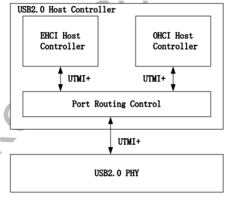
Abbildung 1-1. USB-2.0-Host-Controller.
1.3 USB 2.0 OTG
Kompatibilität: Universal Serial Bus Specification, Revision 2.0. Funktionen:
- Host- und Device-Modus.
- OTG-ID-Erkennung und automatischer Host-/Device-Wechsel anhand des ID-Pegels.
- Keine ADP-/SRP-/HNP-Protokolle.
- Host: High/Full/Low Speed; Device: nur High/Full Speed.
- 9 Host-Kanäle.
- 9 Device-Endpunkte zusätzlich zu Control-Endpunkt 0: 4 IN, 3 OUT, 2 bidirektionale IN/OUT.
- Integrierter FIFO mit 1024x35 bits.
- Internes DMA mit Scatter/Gather.
- Paketbasierte dynamische FIFO-Zuteilung an Endpunkte zur flexiblen, effizienten RAM-Nutzung.
- Dynamische FIFO-Größe.
- Ladeerkennung im Device-Modus.
- UART-Bypass-Modus.
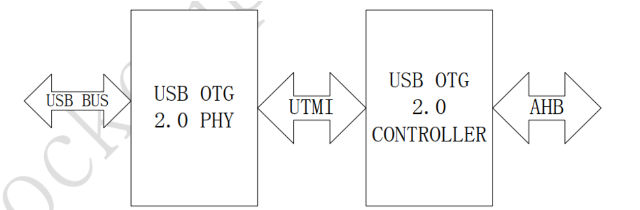
Abbildung 1-2. USB 2.0 OTG.
1.4 USB 3.0 OTG
Kompatible Spezifikationen: Universal Serial Bus 3.0 Specification Revision 1.0; Universal Serial Bus Specification Revision 2.0; eXtensible Host Controller Interface for Universal Serial Bus (xHCI) Revision 1.1.
DWC3 unterstützt Control/Bulk (einschließlich Stream)/Interrupt/Isochronous, gleichzeitige IN-/OUT-Übertragung über USB 3.0 bis 8Gbps, Descriptor Caching und Data Pre-fetching.
USB-3.0-Device-Funktionen:
- Bis zu 7 IN- und 6 OUT-Endpunkte einschließlich Control-Endpunkt 0.
- Bis zu 13 Übertragungsressourcen, eine je Endpunkt.
- Flexible Endpunktkonfiguration für Anwendungen und USB-set-configuration-Modi.
- Hardwareverarbeitung von ERDY und Burst.
- Bulk-Streams mit automatisch vom Controller gestarteter Datenbewegung.
- Isochrone Endpunkte mit Datenpuffern.
- Flexible Deskriptoren für Pufferinterrupt-Steuerung, mehrere Transfers, isochrone und Control-Transfers sowie verteilte Puffer.
USB 3.0 DRD unterstützt statisches Device und Host, USB 3.0/2.0 OTG A/B anhand ID, UFP/DFP und Data Role Swap nach Type-C. Nicht unterstützt werden SRP, HNP und
RSP.
USB-3.0-xHCI-Host-Funktionen:
- Bis zu 64 Geräte.
- Ein Interrupter.
- Ein USB-2.0- und ein SuperSpeed-Port.
- Gleichzeitiger USB-3.0-/2.0-Verkehr bis 8.48Gbps laut englischer Quelle.
- Standardmäßige oder quelloffene xHCI- und Klassentreiber.
- xHCI Debug Capability.
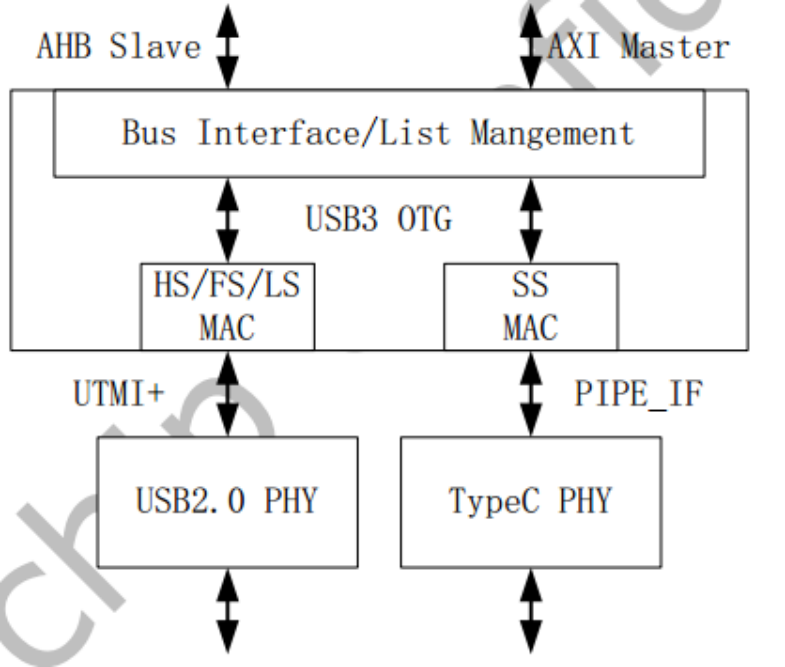
Abbildung 1-3. USB 3.0 OTG.
1.5 USB 2.0 PHY
USB-2.0-PHYs gibt es mit einem oder zwei Ports. Abbildung 1-4 zeigt die Zwei-Port-Ausführung.
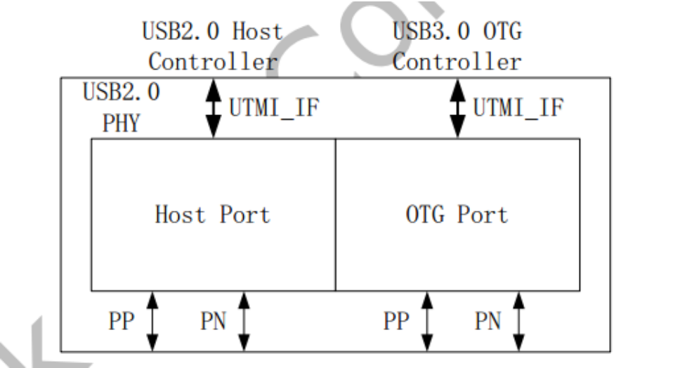
Abbildung 1-4. USB 2.0 PHY. Host Port ist über UTMI+ mit dem USB-2.0-Host-Controller verbunden. OTG Port verbindet über UTMI+ den USB-3.0-OTG-Controller beziehungsweise die USB-2.0-Logik des USB-2.0-OTG-Controllers.
1.6 Type-C USB 3.0 PHY
Unterstützt werden:
- USB 3.0, nur SuperSpeed.
- DisplayPort 1.3, nur RBR-, HBR- und HBR2-Datenraten.
- DisplayPort AUX.
- USB Type-C und DisplayPort Alt Mode.
- DisplayPort Alt Mode mit Type-C-Pinbelegungen A, B, C, D, E und F.
- Normale und gedrehte Steckrichtung.
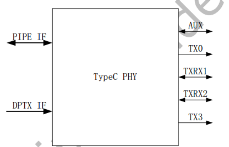
Abbildung 1-5. Type-C PHY.
2. Hardwareschaltungen und Signale
2.1 USB-2.0-Host-Schaltungen
Dieser Abschnitt beschreibt Schaltungen und Signale für USB 2.0 Host. Je nach verwendetem
USB-2.0-PHY wird zwischen gewöhnlicher USB-2.0-Host- und USB-2.0-HSIC-Schaltung unterschieden.
2.1.1 Gewöhnliche USB-2.0-Host-Schaltung
USB 2.0 arbeitet mit 480MHz. Die Quelle empfiehlt 7–8 MIL breite DP-/DM-Leiterbahnen und 90 Ω Differenzimpedanz. Bevorzugt wird eine Außenlage mit Massefläche, ohne benachbarte Störquelle und ohne andere Signalleitungen unmittelbar darüber oder darunter. Beispiel ist der USB-2.0-Host von RK3399. Abbildung 2-1 zeigt die SoC-Pins.
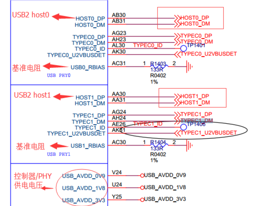
Abbildung 2-1. USB-2.0-Host-Pins des SoC. VBUS-Steuerung und Schnittstellenschaltung zeigen Abbildungen 2-2 und 2-3.
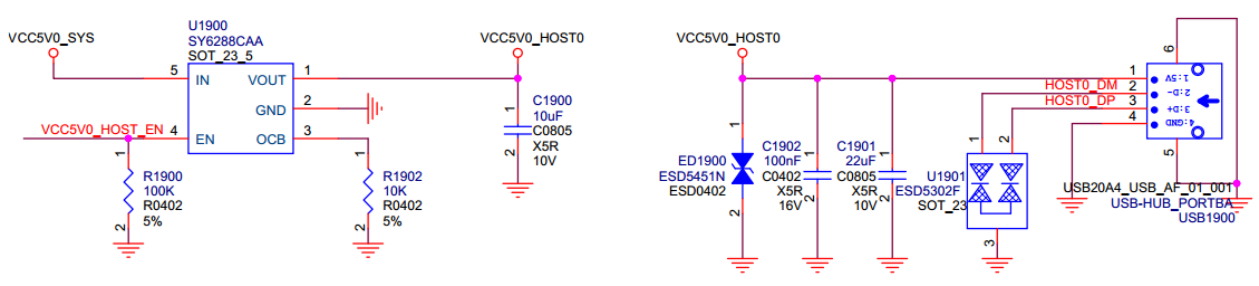
Abbildung 2-2. USB-2.0-Host-VBUS-Steuerung und Schnittstelle.

Abbildung 2-3. GPIO-Steuerpin für USB-2.0-Host-VBUS.
2.1.2 USB-2.0-HSIC-Schaltung
HSIC (High Speed Inter Chip) nutzt 240MHz DDR und erreicht wie USB 2.0 480Mbps. Die typische Leitungsimpedanz beträgt 50 Ω; empfohlen sind höchstens 10cm Leiterbahnlänge. In Abbildung 2-4 ist USIC_STROBE das 240MHz-DDR-Signal und USIC_DATA das Datensignal. Versorgungsspannungen sind nur 0.9V und 1.2V; der Standardsignalpegel ist 1.2V. Der Verbrauch ist geringer als bei USB-2.0-PHY. Beispiel: HSIC von RK3399.
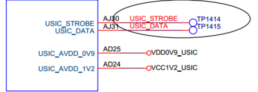
Abbildung 2-4. USB-2.0-HSIC-Pins des SoC.
2.2 USB-OTG-Schaltungen
2.2.1 USB-2.0-OTG-Schaltung
USB-2.0-OTG-Signale:
- OTG_DP/OTG_DM: differenzielle D+/D-, jeweils mit 2.2Ω Serienwiderstand.
- USB_DET: Eingang zur Erkennung eines Hosts oder Ladegeräts im Peripheral-Modus. Standardmäßig 0V, bei Verbindung 3.0–3.2V.
- USB_ID bestimmt Host/Peripheral. Standardmäßig 1.8V durch internen Pull-up, also Peripheral. Ein OTG-Host-Kabel zieht ID auf Masse; der Treiber wechselt bei High→Low zu Host.
- USB_RBIAS ist der Referenzwiderstand des PHY. Da sein Wert die USB-Signalamplitude beeinflusst, ist die SDK-Referenzschaltung strikt einzuhalten.
- VCC5V0_OTG ist im Peripheral-Modus die Eingangsquelle für USB_DET und versorgt im Host-Modus Geräte mit 5V VBUS.
- USB_AVDD_1V0/USB_AVDD_1V8/USB_AVDD_3V3 versorgen den USB-2.0-OTG-PHY.
Die vollständige Referenzschaltung zeigen Abbildungen 2-5–2-8 am PX30 EVB.
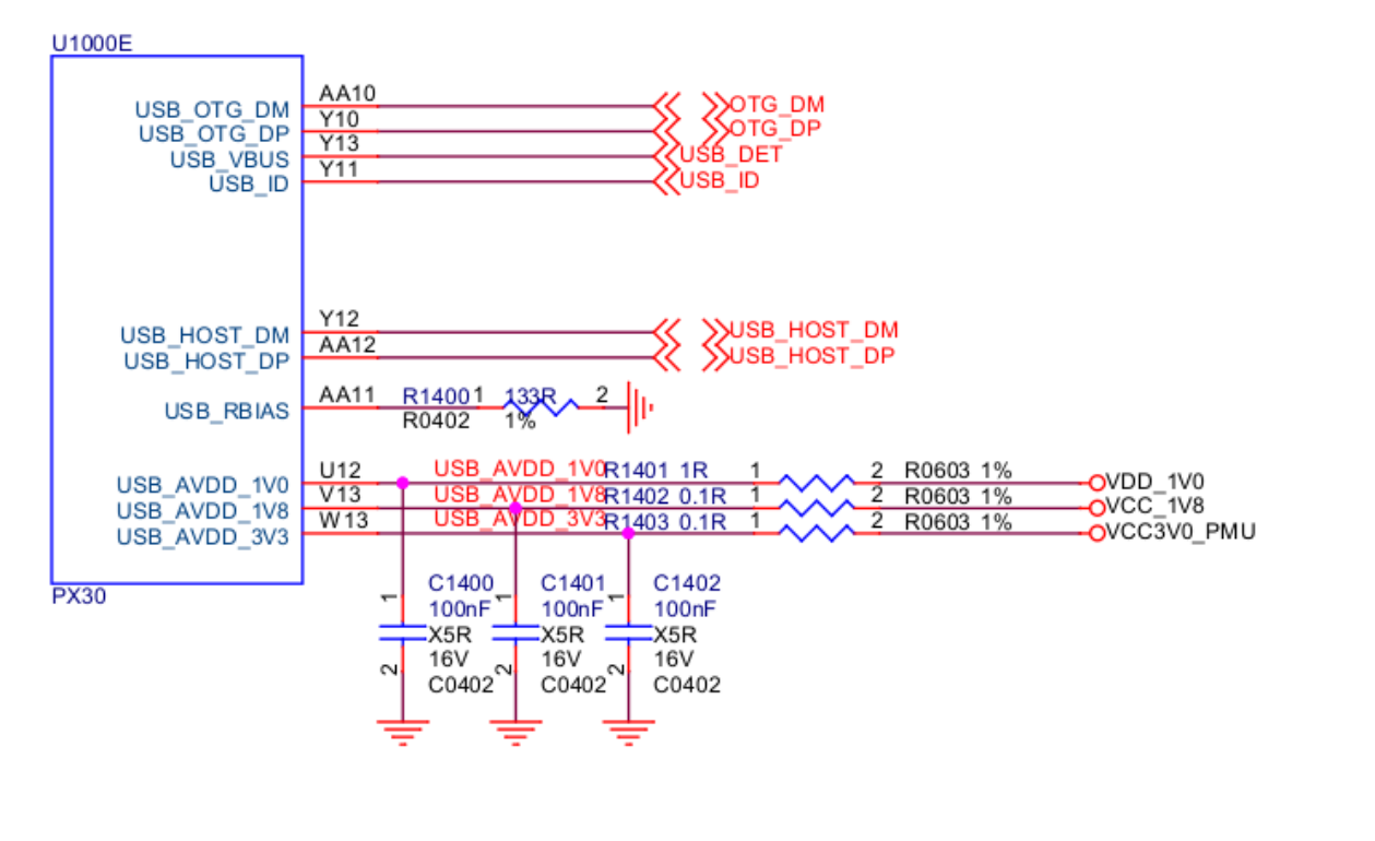
Abbildung 2-5. USB-2.0-OTG-Pins des SoC.
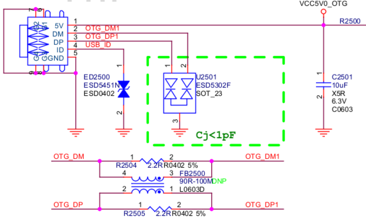
Abbildung 2-6. USB-2.0-OTG-Micro-Schnittstelle.
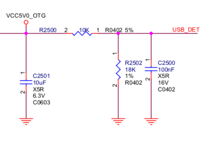
Abbildung 2-7. USB-2.0-OTG_DET-Schaltung.
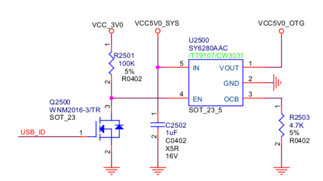
Abbildung 2-8. USB-2.0-OTG_DRV-Schaltung.
2.2.2 USB-3.0-OTG-Schaltung
USB 3.0 OTG erreicht maximal 5Gbps und ist abwärtskompatibel zu USB 2.0 OTG. Der Anschluss ist Type-C oder Type-A. Unterstützt werden vieradrige differenzielle Signalleitungen mit bis zu 3m Kabel und 11 Zoll PCB. Die differenzielle Übertragung vermindert Störungen bei 5Gbps über lange Kabel. Abbildungen 2-9–2-14 zeigen die Type-C-USB-3.0-Schaltung von RK3399.

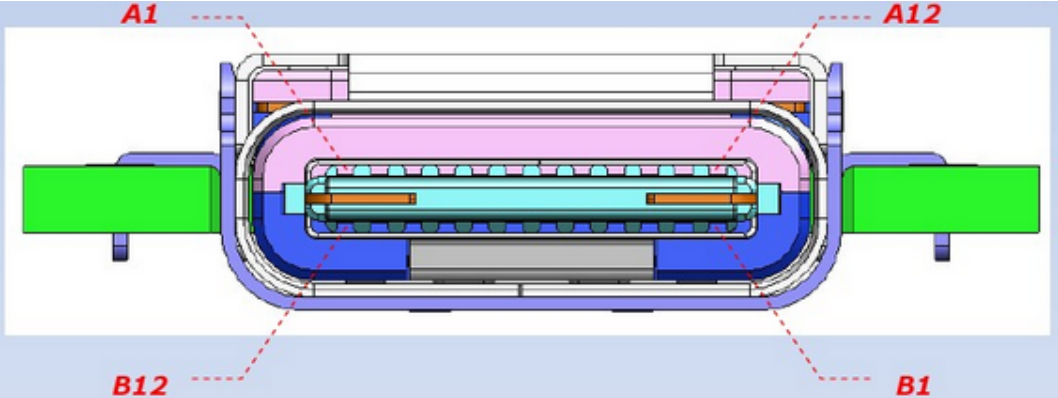
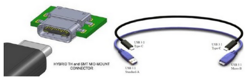
Abbildung 2-9. Type-C-Pinbelegung.
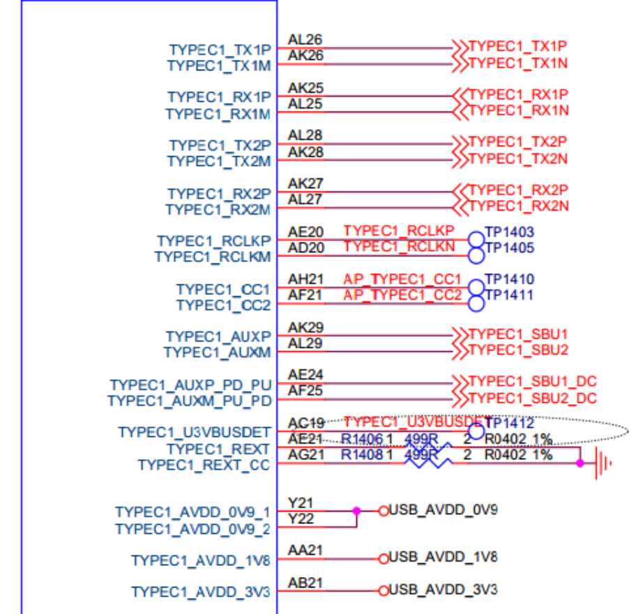
Abbildung 2-10. USB-3.0-OTG-Pins des SoC.
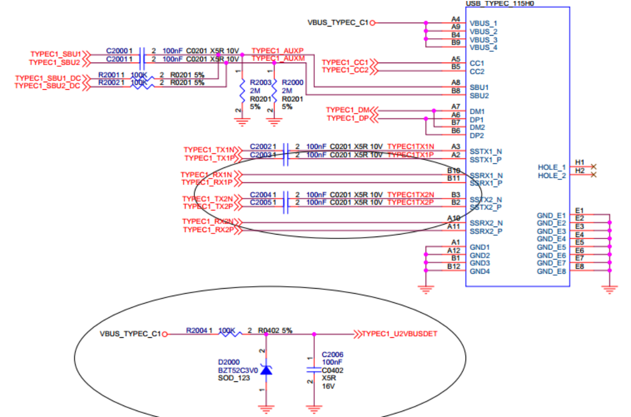
Abbildung 2-11. USB-3.0-OTG-Type-C-Schnittstelle.
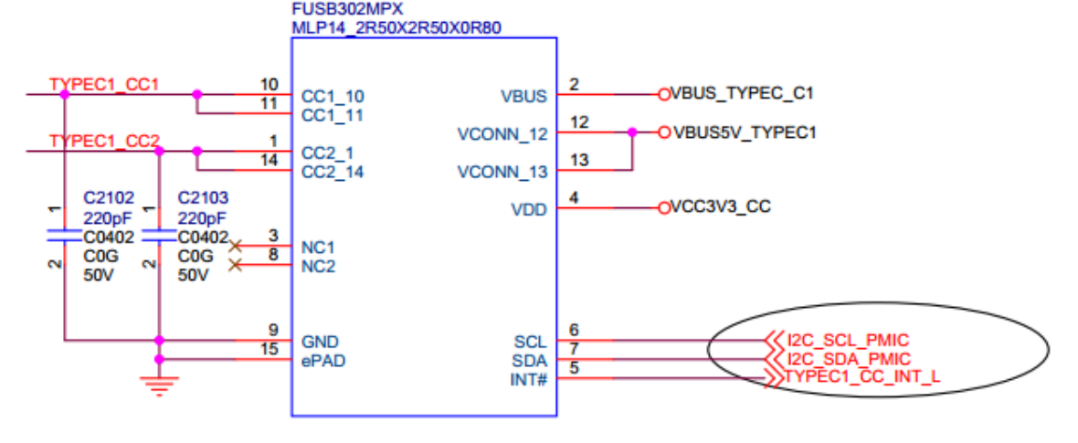
Abbildung 2-12. Type-C-CC-Erkennung mit FUSB302.
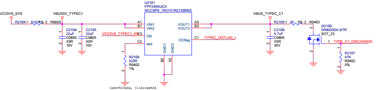

Abbildung 2-13. USB-3.0-VBUS-Steuerung 1: GPIO.
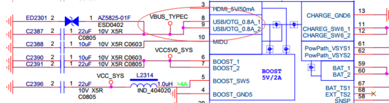
Abbildung 2-14. USB-3.0-VBUS-Steuerung 2: RK818.
2.3 USB-GPIO-Schaltungen
USB-GPIO-Anwendungen:
- VBUS Regulator GPIO schaltet 5V im Host-Modus ein oder aus.
- VBUSDET GPIO erkennt Device-Hotplug anhand des VBUS-Pegels und steuert Ladeerkennung sowie dynamisches PHY-Energiemanagement.
- OTG_ID GPIO wechselt Device/Host, gewöhnlich an Micro/Mini USB2.0. Type-C benötigt eine CC-zu-ID-Umsetzung.
VBUS Regulator GPIO ist bei Rockchip üblich; deshalb behandelt dieser Abschnitt nur VBUSDET und OTG_ID. Fehlen herausgeführte VBUSDET-/OTG_ID-Pins, etwa bei RK3506G, ist GPIO-Erkennung für Device-Hotplug und automatischen Rollenwechsel anhand des Anschluss-ID-Pegels erforderlich.
2.3.1 USB-VBUSDET-GPIO-Schaltung
VBUSDET GPIO erkennt Device-Hotplug ähnlich dem gewöhnlichen PHY-VBUSDET. Bei Chips ohne herausgeführten Pin, etwa RK3506G, kann GPIO VBUS-Änderungen erkennen und Ladeerkennung sowie PHY-Energieverwaltung steuern. Der Verbindungsbeginn im Device-Modus hängt nicht davon ab; GPIO ist daher nicht grundsätzlich erforderlich. Benötigt wird er in folgenden Fällen:
- Device benötigt Ladeerkennung oder dynamischen PHY-suspend/normal-Wechsel zur Verbrauchssenkung.
- Device muss USB-Trennung erkennen.
Nicht benötigt wird VBUSDET GPIO in folgenden Fällen:
- Der PHY-VBUSDET-Pin ist bereits herausgeführt, etwa bei RK3506B; ein zusätzlicher
GPIO ist nicht nötig.
- OTG arbeitet nur als Host; Device wird lediglich zum Firmware-Schreiben benötigt.
- Device benötigt weder Ladeerkennung noch dynamisches PHY-Energiemanagement; USB2 PHY darf dauerhaft in Normal bleiben. Dann wird jedoch USB-Trennung nicht erkannt. Falls dies erforderlich ist, muss der Controllertreiber manuell angepasst werden, um Disconnect anhand des Suspend-Interrupts zu erkennen.
Abbildung 2-15 zeigt RK3506G_EVB1. Zwischen Anschluss-VBUS und GPIO invertiert ein Transistor den Pegel: VBUS High ergibt GPIO Low und VBUS Low ergibt GPIO High. Bei selbstversorgten Geräten verhindert dies Leckstrom von Host-VBUS in den ausgeschalteten Chip und mögliche Anschlussprobleme.
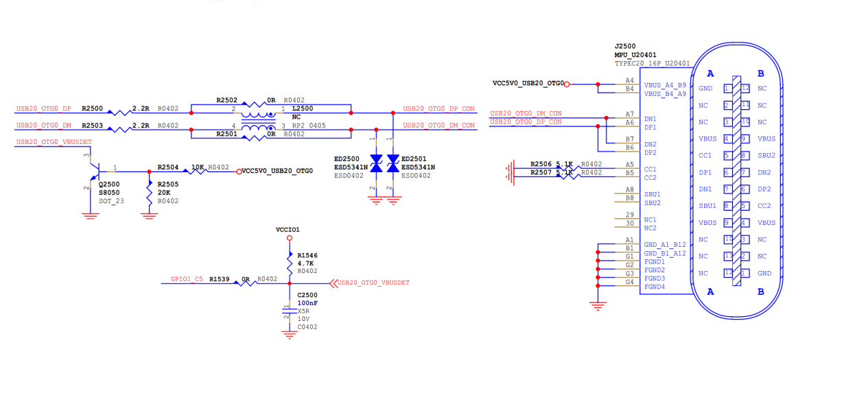
Abbildung 2-15. VBUSDET-GPIO-Schaltung.
2.3.2 USB-OTG_ID-GPIO-Schaltung
OTG_ID GPIO ermöglicht automatischen Device-/Host-Wechsel, meist mit Micro/Mini USB2.0. Type-C erfordert CC-zu-ID-Umsetzung. Anwendungsauswahl:
Auch ohne herausgeführten PHY-ID-Pin ist ID GPIO nicht zwingend, da die Befehle unter „Häufig verwendete USB-Befehle“ die Rollen wechseln können. ID GPIO ist für automatischen Rollenwechsel anhand des eingesteckten Kabels sinnvoll. Nicht benötigt wird er in folgenden Fällen:
- Der PHY-ID-Pin ist herausgeführt, beispielsweise RK3506B.
- Rollenwechsel ist erforderlich, darf aber durch Softwarebefehle erfolgen.
Abbildung 2-16 zeigt RK3506G Test1. Ein externer ID-Pull-up ist nicht nötig. Standard-Device-Kabel lassen ID offen; Host-/OTG-Kabel schließen ID nach GND kurz und signalisieren Host. Entsprechend muss ID GPIO standardmäßig einen schwachen Pull-up für Device aufweisen. Der OTG-Adapter zieht ID nach Low und aktiviert Host.
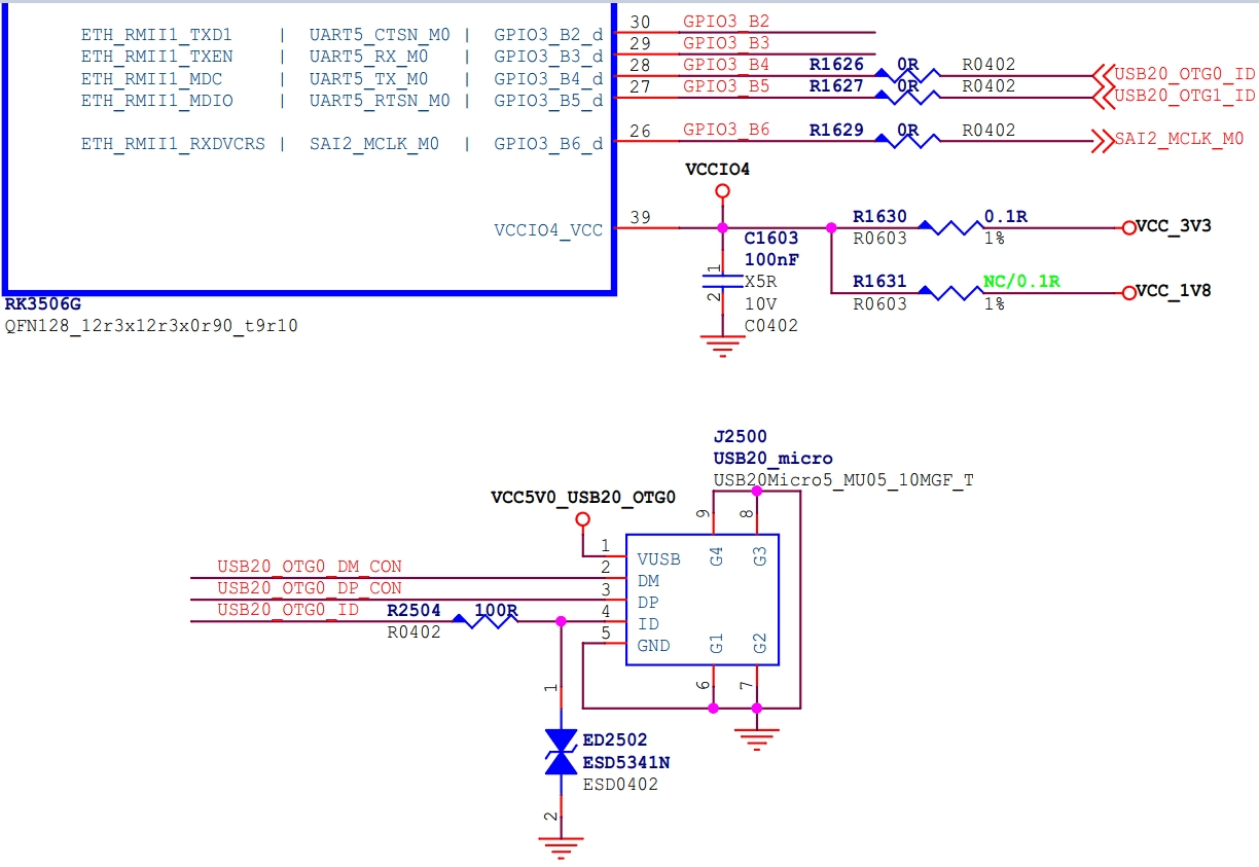
Abbildung 2-16. OTG_ID-GPIO-Schaltung.
3. USB-Konfiguration im Kernel
USB wird wie andere Kernelmodule konfiguriert und gespeichert. Standardkonfiguration laden:
make ARCH=arm64 rockchip_defconfig
Kernelkonfiguration auswählen:
make ARCH=arm64 menuconfig
Konfiguration speichern:
make ARCH=arm64 savedefconfig
rockchip_defconfig durch defconfig ersetzen.
3.1 USB PHY CONFIG
Device Drivers  --->
    PHY Subsystem  --->
        ...
        <*> Rockchip INNO USB2PHY Driver
        ...
        <*> Rockchip TYPEC PHY Driver
        ...
        <*> Rockchip INNO USB 3.0 PHY Driver
Rockchip INNO USB2PHY Driver ist für USB-2.0-PHY mit Innosilicon-IP; Rockchip TYPEC PHY Driver für USB-3.0-PHY, etwa RK3399; Rockchip INNO USB 3.0 PHY Driver für Innosilicon-USB-3.0-PHY, etwa RK3328.
3.2 USB Host CONFIG
Die USB-Host-Konfiguration befindet sich unter:
Device Drivers  --->
        [*] USB support  --->
-*- Support for Host-side USB
...
<*> xHCI HCD (USB 3.0) support
-*- Generic xHCI driver for a platform device
...
<*> EHCI HCD (USB 2.0) support
[ ]     Root Hub Transaction Translators
[*]     Improved Transaction Translator scheduling
<*> Generic EHCI driver for a platform device
...
<*> OHCI HCD (USB 1.1) support
< >     OHCI support for PCI-bus USB controllers
<*>     Generic OHCI driver for a platform device
Zuerst USB support als USB-Basis aktivieren, danach Support for Host-side USB. OHCI unterstützt USB 1.1 Host, EHCI USB 2.0 Host und xHCI USB 3.0 Host.
Hinweis: rk3308_linux_defconfig deaktiviert USB Host zur Kernelverkleinerung, obwohl RK3308 einen USB-2.0-Host mit EHCI/OHCI enthält. Für dessen Nutzung OHCI/EHCI und passende Geräteklassentreiber aktivieren.
3.3 USB OTG CONFIG
Für USB 2.0 OTG DesignWare USB2 DRD Core Support und Betriebsmodus wählen; für USB 3.0 OTG DesignWare USB3 DRD Core Support und Betriebsmodus.
Device Drivers  --->
    -*- Support for Host-side USB
    [*] USB support  --->
        ...
        <*> DesignWare USB2 DRD Core Support
                DWC2 Mode Selection (Dual Role mode)
        ...
        <*> DesignWare USB3 DRD Core Support
                DWC3 Mode Selection (Dual Role mode)
3.4 USB Gadget CONFIG
Rockchip unterstützt standardmäßig Gadget ACM, RNDIS, MSC, MTP, PTP, Accessory, ADB, MIDI und Audio. Weitere Funktionen nach Produktbedarf aktivieren und gleichzeitig die Android-Dateien init.rk30board.usb.rc sowie init.usb.configfs.rc anpassen.
DeviceDrivers  --->
    [*]USB support  --->
        [*] USB Gadget Support  --->
            ...
            USBGadget Drivers (USB functions configurable through configfs)  --->
                [ ]       Generic serial bulk in/out
                [*]       Abstract Control Model (CDC ACM)
                [ ]       Object Exchange Model (CDC OBEX)
                [ ]       Network Control Model (CDC NCM)
                [ ]       Ethernet Control Model (CDC ECM)
                [ ]       Ethernet Control Model (CDC ECM) subset
                [*]       RNDIS
                [ ]       Ethernet Emulation Model (EEM)
                [*]       Mass storage
                [ ]       Loopback and sourcesink function (for testing)
                [*]       Function filesystem (FunctionFS)
                [*]       MTP gadget
                [*]         PTP gadget
                [*]       Accessory gadget
                [*]         Audio Source gadget
                [*]       Uevent notification of Gadget state
                [ ]       Audio Class 1.0
                [ ]       Audio Class 2.0
                [*]       MIDI function
                [ ]       HID function
                [ ]       USB Webcam function
                [ ]       Printer function
3.5 USB-Geräteklassentreiber
3.5.1 Mass Storage Class
USB-Speicher gehört zu SCSI. Vor USB Mass Storage daher die SCSI-Optionen konfigurieren.
Device Drivers --->
    SCSI device support --->
        <*> SCSI device support
[ ] SCSI: use blk-mq I/O path by default
[*] legacy /proc/scsi/ support
    *** SCSI support type (disk, tape, CD-ROM) ***
<*> SCSI disk support
< > SCSI tape support
< > SCSI OnStream SC-x0 tape support
< > SCSI CDROM support
<*> SCSI generic support
<*> SCSI media changer support
[*] Verbose SCSI error reporting (kernel size +=75K)
[*] SCSI logging facility
[*] Asynchronous SCSI scanning
    SCSI Transports  --->
[*] SCSI low-level drivers  --->
[ ] PCMCIA SCSI adapter support  ----
[ ] SCSI Device Handlers  ----
Nach SCSI Device Support USB Mass Storage support unter USB Support aktivieren.
Device Driver --->
    [*] USB support  --->
        <*> USB Mass Storage support
3.5.2 USB Serial Converter
USB-3G-Modem-Unterstützung:
Device Driver --->
    [*] USB support  --->
        <*> USB Serial Converter support  --->
            <*>   USB driver for GSM and CDMA modems
Device Driver --->
    [*] Network device support  --->
        <*>   PPP (point-to-point protocol) support
            <*>     PPP BSD-Compress compression
            <*>     PPP Deflate compression
            [*]     PPP filtering
            <*>     PPP MPPE compression (encryption)
            [*]     PPP multilink support
            <*>     PPP over Ethernet
            <*>     PPP over L2TP
            <*>     PPP on L2TP Access Concentrator
            <*>     PPP on PPTP Network Server
<*>     PPP support for async serial ports
<*>     PPP support for sync tty ports
PL2303-Unterstützung: die gezeigte Konfiguration wählen (die Quelle schreibt an einer Stelle PL203) und USB driver for GSM and CDMA modems deaktivieren. Sonst kann PL2303 fälschlich als 3G-Modem erkannt werden.
Device Driver --->
    [*] USB support  --->
        <*> USB Serial Converter support  --->
            <*> USB Prolific 2303 Single Port Serial Driver
USB GPS, beispielsweise u-blox 6 - GPS Receiver:
Device Drivers  --->
    [*] USB support --->
        [*] USB Modem (CDC ACM) support
3.5.3 USB HID
Für gewöhnliche USB-Mäuse und -Tastaturen folgende HID-Konfiguration wählen:
Device Drivers  --->
    [*] HID support
        [*] USB HID transport layer
        [ ] PID device support
        [*] /dev/hiddev raw HID device support
3.5.4 USB Net
USB-Bluetooth-Konfiguration:
[*] Networking support  --->
    ...
    <*> Bluetooth subsystem support  --->
        Bluetooth device drivers  --->
            ...
            <*> HCI USB driver
            [*]   Broadcom protocol support (NEW)
            [*]   Realtek protocol support (NEW)
            ...
USB Wi-Fi erfordert einen speziellen Herstellertreiber. USB-Ethernet-Konfiguration:
Device Driver --->
    [*] Network device support  --->
        <*> USB Network Adapters  --->
            <*> USB CATC NetMate-based Ethernet device support
            <*> USB KLSI KL5USB101-based ethernet device support
            <*> USB Pegasus/Pegasus-II based ethernet device support
            <*> USB RTL8150 based ethernet device support
            <*> Realtek RTL8152/RTL8153 Based USB Ethernet Adapters
            < > Microchip LAN78XX Based USB Ethernet Adapters
            <*> Multi-purpose USB Networking Framework
            <*>     ASIX AX88xxx Based USB 2.0 Ethernet Adapters
            <*>     ASIX AX88179/178A USB 3.0/2.0 to Gigabit Ethernet
            -*- CDC Ethernet support (smart devices such as cable modems)
            <*> CDC EEM support
            -*- CDC NCM support
            < > Huawei NCM embedded AT channel support
            <*> CDC MBIM support
            <*> Davicom DM96xx based USB 10/100 ethernet devices
            < > CoreChip-sz SR9700 based USB 1.1 10/100 ethernet devices
            < > CoreChip-sz SR9800 based USB 2.0 10/100 ethernet devices
            <*> SMSC LAN75XX based USB 2.0 gigabit ethernet devices
            <*> SMSC LAN95XX based USB 2.0 10/100 ethernet devices
            <*> GeneSys GL620USB-A based cables
            <*> NetChip 1080 based cables (Laplink, ...)
            <*> Prolific PL-2301/2302/25A1/27A1 based cables
            <*> MosChip MCS7830 based Ethernet adapters
            <*> Host for RNDIS and ActiveSync devices
            <*> Simple USB Network Links (CDC Ethernet subset)
            [*]     ALi M5632 based 'USB 2.0 Data Link' cables
            [*]     AnchorChips 2720 based cables (Xircom PGUNET, ...)
            [*]     eTEK based host-to-host cables (Advance, Belkin, ...)
            [*]     Embedded ARM Linux links (iPaq, ...)
            [*]     Epson 2888 based firmware (DEVELOPMENT)
            [*]     KT Technology KC2190 based cables (InstaNet)
<*> Sharp Zaurus (stock ROMs) and compatible
<*> Conexant CX82310 USB ethernet port
<*> Samsung Kalmia based LTE USB modem
<*> QMI WWAN driver for Qualcomm MSM based 3G and LTE modems
<*> Option USB High Speed Mobile Devices
<*> Intellon PLC based usb adapter
<*> Apple iPhone USB Ethernet driver
<*> USB-to-WWAN Driver for Sierra Wireless modems
< > LG VL600 modem dongle
< > QingHeng CH9200 USB ethernet support
3.5.5 USB Camera
Device Driver --->
    <*> Multimedia support  --->
        [*]   Media USB Adapters  --->
            *** Webcam devices ***
            <*> USB Video Class (UVC)
            [*] UVC input events device support
3.5.6 USB Audio
Device Driver --->
    <*> Sound card support  --->
        <*> Advanced Linux Sound Architecture --->
            ...
            [*] USB sound devices   --->
                [*] USB Audio /MIDI driver
3.5.7 USB HUB
Disable external HUBs deaktivieren, um externe USB-Hubs zu unterstützen.
Device Drivers --->
    [*] USB support --->
        -*- Support for Host-side USB
        ...
        [ ]     Disable external hubs
Weitere Geräte wie GPS und Drucker benötigen gegebenenfalls Hersteller- oder Standardklassentreiber. Entsprechende Verfahren können im Internet recherchiert und direkt verwendet werden; Rockchip stellt keine besonderen Anforderungen.
4. USB-DTS-Konfiguration
4.1 USB-2.0-/3.0-PHY-DTS
USB-2.0- und USB-3.0-PHY sind unabhängig und unterscheiden sich erheblich; DTS muss getrennt konfiguriert werden. RK3399 ist besonders flexibel und komplex: siehe Rockchip_RK3399_Developer_Guide_USB_DTS_CN.
4.1.1 USB-2.0-PHY-DTS
Rockchip nutzt hauptsächlich Innosilicon- und Synopsis-USB-2.0-PHY-IP. Die unterschiedliche Hardware verlangt verschiedene DTS-Konfigurationen. Meist wird Innosilicon eingesetzt.
- DTS-Dokumentation:
- Innosilicon außer RK3188/RK3288:
Documentation/devicetree/bindings/phy/phy-rockchip-inno-usb2.txt. - Synopsis für RK3188/RK3288:
Documentation/devicetree/bindings/phy/rockchip-usb-phy.txt.
- Beispiel RK3399 USB 2.0 PHY0. Die Register liegen im GRF; daher ist GRF mit seiner Basisadresse der Elternknoten. Der PHY kombiniert Host und OTG mit gemeinsamem Referenztakt, 480MHz-Ausgang und GRF-Registeroffset. Jeder Port erhält einen Unterknoten namens otg-port beziehungsweise host-port. Die Interrupts unterscheiden sich.
grf: syscon@ff770000 {
    compatible = "rockchip,rk3399-grf", "syscon", "simple-mfd";
    reg = <0x0 0xff770000 0x0 0x10000>;
    #address-cells = <1>;
    #size-cells = <1>;
    u2phy0: usb2-phy@e450 {
        compatible = "rockchip,rk3399-usb2phy";
        reg = <0xe450 0x10>;
        clocks = <&cru SCLK_USB2PHY0_REF>;
        clock-names = "phyclk";
        #clock-cells = <0>;
        clock-output-names = "clk_usbphy0_480m";
        status = "disabled";

        u2phy0_host: host-port {
            #phy-cells = <0>;
            interrupts = <GIC_SPI 27 IRQ_TYPE_LEVEL_HIGH 0>;
            interrupt-names = "linestate";
            status = "disabled";
        };

        u2phy0_otg: otg-port {
            #phy-cells = <0>;
            interrupts = <GIC_SPI 103 IRQ_TYPE_LEVEL_HIGH 0>,
                         <GIC_SPI 104 IRQ_TYPE_LEVEL_HIGH 0>,
                         <GIC_SPI 106 IRQ_TYPE_LEVEL_HIGH 0>;
            interrupt-names = "otg-bvalid", "otg-id",
                              "linestate";
            status = "disabled";
        };
    };
};
Für Host und OTG im Host-Modus kann im Board-DTS optional ein VBUS-5V-Regler nötig sein. Bei RK3399 schaltet GPIO High 5V ein und Low aus. GPIO wird als regulator konfiguriert. regulator-always-on hält ihn vom Systemstart bis zum Abschalten High und VBUS eingeschaltet.
vcc5v0_host: vcc5v0-host-regulator {
    compatible = "regulator-fixed";
    enable-active-high;
    gpio = <&gpio4 25 GPIO_ACTIVE_HIGH>;
    pinctrl-names = "default";
    pinctrl-0 = <&host_vbus_drv>;
    regulator-name = "vcc5v0_host";
    regulator-always-on;
};

usb2 {
    host_vbus_drv: host-vbus-drv {
        rockchip,pins =
                <4 25 RK_FUNC_GPIO &pcfg_pull_none>;
    };
};
phy-supply auf den VBUS-5V-Regler vcc5v0_host setzen. Das PHY-Framework wertet dies automatisch aus und steuert den VBUS-GPIO.
u2phy0_host: host-port {
    phy-supply = <&vcc5v0_host>;
    status = "okay";
};
4.1.2 USB-3.0-PHY-DTS
Rockchip verwendet Type-C PHY, Innosilicon USB 3.0 PHY und Innosilicon USB 3.0 CombPhy. Ihre unterschiedliche Hardware benötigt unterschiedliche DTS-Konfigurationen.
- Dokumentation:
- Type-C für RK3399/RK3399Pro:
Documentation/devicetree/bindings/phy/phy-rockchip-typec.txt. - Innosilicon USB 3.0 für RK3228H/RK3228 laut Quelle:
Documentation/devicetree/bindings/phy/phy-rockchip-inno-usb3.txt. - Innosilicon USB-3.0-/PCIe-Combphy RK1808:
Documentation/devicetree/bindings/phy/phy-rockchip-inno-combophy.txt.
- Beispiel RK3399 Type-C0. Type-C PHY kombiniert USB 3.0 SuperSpeed und DisplayPort-Sender; tcphy0 besitzt deshalb tcphy0_dp und tcphy0_usb3. Eigenschaften:
- rockchip,grf: phandle zum GRF-syscon.
- rockchip,typec-conn-dir: Register der Steckrichtung.
- rockchip,usb3tousb2-en: Register zum Erzwingen von USB3→USB2.
- rockchip,external-psm: Register des externen PSM-Takts.
- rockchip,pipe-status: PIPE-Statusregister.
- rockchip,uphy-dp-sel: Register zur PHY-Auswahl für DP.
tcphy0: phy@ff7c0000 {
    compatible = "rockchip,rk3399-typec-phy";
    reg = <0x0 0xff7c0000 0x0 0x40000>;
    rockchip,grf = <&grf>;
    #phy-cells = <1>;
    clocks = <&cru SCLK_UPHY0_TCPDCORE>,
             <&cru SCLK_UPHY0_TCPDPHY_REF>;
    clock-names = "tcpdcore", "tcpdphy-ref";
    assigned-clocks = <&cru SCLK_UPHY0_TCPDCORE>;
    assigned-clock-rates = <50000000>;
    power-domains = <&power RK3399_PD_TCPD0>;
    resets = <&cru SRST_UPHY0>,
             <&cru SRST_UPHY0_PIPE_L00>,
             <&cru SRST_P_UPHY0_TCPHY>;
    reset-names = "uphy", "uphy-pipe", "uphy-tcphy";
    rockchip,typec-conn-dir = <0xe580 0 16>;
    rockchip,usb3tousb2-en = <0xe580 3 19>;
    rockchip,usb3-host-disable = <0x2434 0 16>;
    rockchip,usb3-host-port = <0x2434 12 28>;
    rockchip,external-psm = <0xe588 14 30>;
    rockchip,pipe-status = <0xe5c0 0 0>;
    rockchip,uphy-dp-sel = <0x6268 19 19>;
    status = "disabled";

    tcphy0_dp: dp-port {
        #phy-cells = <0>;
    };

    tcphy0_usb3: usb3-port {
        #phy-cells = <0>;
    };
};
RK3399 hat zwei nahezu identische Type-C-PHYs. Hier ist nur DTSI beschrieben. Weitere DTS-Eigenschaften wie extcon und CC-Chip FUSB302 stehen in Rockchip_RK3399_Developer_Guide_USB_CN.
4.2 USB-2.0-Controller-DTS
Zwei Architekturen:
- EHCI (Enhanced Host Controller Interface), nur USB 2.0, zusammen mit OHCI (Open Host Controller Interface), USB 1.1/1.0.
- DWC2 (DesignWare Cores USB 2.0 Hi-Speed OTG), USB 2.0/1.1/1.0.
Im Folgenden werden beide DTS-Architekturen beschrieben.
4.2.1 USB-2.0-Host-DTS
- Dokumentation:
Documentation/devicetree/bindings/usb/usb-ehci.txt
Documentation/devicetree/bindings/usb/usb-ohci.txt
- Beispiel RK3399 Host0 EHCI/OHCI. compatible ist fest generic-ehci beziehungsweise generic-ohci. Beide teilen clocks und phys. power-domains nur konfigurieren, wenn der SoC-Controller diese Funktion unterstützt.
usb_host0_ehci: usb@fe380000 {
    compatible = "generic-ehci";
    reg = <0x0 0xfe380000 0x0 0x20000>;
    interrupts = <GIC_SPI 26 IRQ_TYPE_LEVEL_HIGH 0>;
    clocks = <&cru HCLK_HOST0>, <&cru HCLK_HOST0_ARB>,
             <&cru SCLK_USBPHY0_480M_SRC>;
    clock-names = "hclk_host0", "hclk_host0_arb", "usbphy0_480m";
    phys = <&u2phy0_host>;
    phy-names = "usb";
    power-domains = <&power RK3399_PD_PERIHP>;
    status = "disabled";
};

usb_host0_ohci: usb@fe3a0000 {
    compatible = "generic-ohci";
    reg = <0x0 0xfe3a0000 0x0 0x20000>;
    interrupts = <GIC_SPI 28 IRQ_TYPE_LEVEL_HIGH 0>;
    clocks = <&cru HCLK_HOST0>, <&cru HCLK_HOST0_ARB>,
             <&cru SCLK_USBPHY0_480M_SRC>;
    clock-names = "hclk_host0", "hclk_host0_arb", "usbphy0_480m";
    phys = <&u2phy0_host>;
    phy-names = "usb";
    power-domains = <&power RK3399_PD_PERIHP>;
    status = "disabled";
};
4.2.2 USB-2.0-OTG-DTS
- USB 2.0 OTG nutzt DWC2. Linux-4.4 enthält dwc2 und den älteren dwc_otg_310 ausschließlich für RK3288/RK3368. Ab Linux-4.19 verwenden alle SoCs dwc2; der alte Treiber wird nicht unterstützt.
Für dwc2 ab Linux-4.4:
Documentation/devicetree/bindings/usb/dwc2.txt
Documentation/devicetree/bindings/usb/generic.txt
Für dwc_otg_310 ausschließlich Linux-4.4 RK3288/RK3368:
Documentation/devicetree/bindings/usb/rockchip-usb.txt
- Beispiel RK3328 USB 2.0 OTG. Eigenschaften:
- dr_mode: host, peripheral oder otg; siehe usb/generic.txt.
- g-rx-fifo-size: Gadget-RX-FIFO.
- g-np-tx-fifo-size: nichtperiodischer Gadget-TX-FIFO.
- g-tx-fifo-size: TX-FIFO je Endpunkt außer ep0.
- g-use-dma: Gadget-DMA aktivieren.
- phys: PHY-Provider.
- phy-names: usb2-phy.
Die drei FIFO-Eigenschaften nach Device-Anwendung konfigurieren:
- g-np-tx-fifo-size setzt den FIFO von Endpunkt 0; empfohlen sind 16 Einheiten à 4Bytes.
- g-rx-fifo-size setzt den gemeinsamen RX-FIFO aller OUT-Endpunkte; empfohlen sind 275 Einheiten à 4Bytes.
- g-tx-fifo-size setzt den separaten TX-FIFO jedes IN-Endpunkts. Nur tatsächlich verwendete IN-Endpunkte konfigurieren; dabei gelten zwei Regeln:
- TX-FIFO darf nicht kleiner als EP max-packet sein.
- Größerer TX-FIFO verbessert den Durchsatz; bei genügend Speicher mindestens das Doppelte von EP max-packet wählen.
usb20_otg: usb@ff580000 {
    compatible = "rockchip,rk3328-usb", "rockchip,rk3066-usb",
                 "snps,dwc2";
    reg = <0x0 0xff580000 0x0 0x40000>;
    interrupts = <GIC_SPI 23 IRQ_TYPE_LEVEL_HIGH>;
    clocks = <&cru HCLK_OTG>, <&cru HCLK_OTG_PMU>;
    clock-names = "otg", "otg_pmu";
    dr_mode = "otg";
    g-np-tx-fifo-size = <16>;
    g-rx-fifo-size = <275>;
    g-tx-fifo-size = <256 128 128 64 64 32>;
    g-use-dma;
    phys = <&u2phy_otg>;
    phy-names = "usb2-phy";
    status = "disabled";
};
4.3 USB-3.0-Controller-DTS
4.3.1 USB-3.0-Host-DTS
xHCI ist im DWC3-OTG-IP integriert und benötigt kein separates DTS. DWC3 konfigurieren und dr_mode auf otg oder host setzen.
4.3.2 USB-3.0-OTG-DTS
- USB 3.0 OTG verwendet DWC3. DTS in Linux-4.4 und Linux-4.19 beziehungsweise neuer
unterscheiden sich wegen der erheblichen DWC3-Treiberaktualisierung; siehe Abschnitt zum USB-3.0-OTG-Treiber.
Linux-4.4:
Documentation/devicetree/bindings/usb/dwc3.txt: allgemeine DWC3-Eigenschaften.Documentation/devicetree/bindings/usb/generic.txt: allgemeine USB-Eigenschaften.Documentation/devicetree/bindings/usb/rockchip,dwc3.txt: RK3399/RK1808.Documentation/devicetree/bindings/usb/rockchip-inno,dwc3.txt: RK3328/RK3228H.
Linux-4.19 und neuer verwenden dwc3.txt, generic.txt und
Documentation/devicetree/bindings/usb/rockchip-inno,dwc3.txt für RK3328/RK3228H.
In Linux-4.4 liegen power-domains, resets (englischer Quelltext: restets) und extcon im Elternknoten usbdrd3; in Linux-4.19 im Unterknoten usbdrd_dwc3. Bei Type-C→Type-A USB 2.0/3.0 OTG benötigt Linux-4.19 extcon in usbdrd_dwc3 für softwareseitigen Rollenwechsel, Linux-4.4 dagegen nicht.
- RK3399-Beispiel für Linux-4.4: Elternknoten usbdrd3_0, Unterknoten usbdrd_dwc3_0. Außer RK3328/RK3228H benötigen alle DWC3-SoCs im Eltern-compatible rockchip,rk3399-dwc3; Unterknoten verwenden snps,dwc3. Der Elternknoten konfiguriert chipbezogene clocks, power-domains und reset; der Unterknoten controllerbezogene Eigenschaften einschließlich für alle DWC3 geltender Quirks.
usbdrd3_0: usb0 {
        compatible = "rockchip,rk3399-dwc3";
        clocks = <&cru SCLK_USB3OTG0_REF>, <&cru SCLK_USB3OTG0_SUSPEND>,
             <&cru ACLK_USB3OTG0>, <&cru ACLK_USB3_GRF>;
        clock-names = "ref_clk", "suspend_clk",
                  "bus_clk", "grf_clk";
        power-domains = <&power RK3399_PD_USB3>;
        resets = <&cru SRST_A_USB3_OTG0>;
        reset-names = "usb3-otg";
        #address-cells = <2>;
        #size-cells = <2>;
        ranges;
        status = "disabled";

        usbdrd_dwc3_0: dwc3@fe800000 {
            compatible = "snps,dwc3";
            reg = <0x0 0xfe800000 0x0 0x100000>;
            interrupts = <GIC_SPI 105 IRQ_TYPE_LEVEL_HIGH 0>;
            dr_mode = "otg";
            phys = <&u2phy0_otg>, <&tcphy0_usb3>;
            phy-names = "usb2-phy", "usb3-phy";
            phy_type = "utmi_wide";
            snps,dis_enblslpm_quirk;
            snps,dis-u2-freeclk-exists-quirk;
            snps,dis_u2_susphy_quirk;
            snps,dis-del-phy-power-chg-quirk;
            snps,tx-ipgap-linecheck-dis-quirk;
            snps,xhci-slow-suspend-quirk;
            snps,xhci-trb-ent-quirk;
            snps,usb3-warm-reset-on-resume-quirk;
        status = "disabled";
    };
};
4.4 USB-GPIO-DTS
Ab Linux-6.1 unterstützt das Rockchip-SDK USB VBUSDET/GPIO mit drivers/extcon/extcon-usb-gpio.c. Der Treiber initialisiert GPIO, verarbeitet Interrupts und meldet Ereignisse über extcon an den PHY. Dieser erkennt anhand EXTCON_USB/EXTCON_USB_HOST Device-Hotplug und wechselt OTG-Modi. Einzelheiten siehe GPIO-Treiber und Softwareablauf.
4.4.1 VBUSDET-GPIO-DTS
Beispiel RK3506G EVB1: Laut Hardwareentwurf ist VBUSDET GPIO GPIO1_C5. DTS-Referenz:
extcon_usb: extcon-usb {
        compatible = "linux,extcon-usb-gpio";
        /* The hardware design inverts the voltage level, so it must be configured as
GPIO_ACTIVE_LOW here. */
        vbus-gpio = <&gpio1 RK_PC5 GPIO_ACTIVE_LOW>;
        pinctrl-names = "default";
        pinctrl-0 = <&usb_extcon_vbus>;
        status = "okay";
};

&pinctrl {
        usb {
                usb_extcon_vbus: usb-extcon-vbus {
                rockchip,pins = <1 RK_PC5 RK_FUNC_GPIO &pcfg_pull_none>;
            };
        };
};

&u2phy_otg0 {
        /* Add the property rockchip,gpio-vbus-det, indicating that the PHY driver supports
VBUS GPIO detection method. */
        rockchip,gpio-vbus-det;
        status = "okay";
};

&usb2phy {
        extcon = <&extcon_usb>;
        status = "okay";
};
Bei nicht herausgeführtem VBUSDET und fehlender VBUSDET-GPIO-Schaltung entfällt diese Konfiguration. Dann aber rockchip,vbus-always-on in u2phy_otg0 ergänzen; damit werden Ladeerkennung und dynamischer Suspend des USB2-PHY-OTG0-Ports deaktiviert.
&u2phy_otg0 {
        rockchip,vbus-always-on;
};
4.4.2 OTG_ID-GPIO-DTS
Beispiel RK3506G TEST1: ID GPIO entspricht GPIO3_B4. DTS-Referenz:
extcon_usb: extcon-usb {
        compatible = "linux,extcon-usb-gpio";
        id-gpio = <&gpio3 RK_PB4 GPIO_ACTIVE_HIGH>;
        /* Must set pinctrl-names to "default", otherwise the pcfg_pull_up configuration
will not take effect. */
        pinctrl-names = "default";
        pinctrl-0 = <&usb_extcon_id>;
        status = "okay";
};

&pinctrl {
        usb {
                usb_extcon_id: usb-extcon-id {
                        /* The ID should be internally pulled high by default, so it should
be configured as pcfg_pull_up. */
                        rockchip,pins = <3 RK_PB4 RK_FUNC_GPIO &pcfg_pull_up>;
                };
        };
};

&u2phy_otg0 {
        /* Add the property rockchip,gpio-id-det, indicating that the PHY driver supports ID
GPIO detection method. */
        rockchip,gpio-id-det;
        status = "okay";
};

&usb2phy {
        extcon = <&extcon_usb>;
        status = "okay";
};
4.4.3 VBUSDET-/OTG_ID-GPIO-DTS
Sind ID und USB_VBUSDET nicht herausgeführt, etwa RK3506G, und werden beide GPIO-Funktionen benötigt, gilt folgende Referenz anhand RK3506G TEST1:
extcon_usb: extcon-usb {
        compatible = "linux,extcon-usb-gpio";
        vbus-gpio = <&gpio3 RK_PB2 GPIO_ACTIVE_LOW>;
        id-gpio = <&gpio3 RK_PB4 GPIO_ACTIVE_HIGH>;
        /* Must set pinctrl-names to "default", otherwise the pcfg_pull_up configuration
will not take effect. */
        pinctrl-names = "default";
        /* pinctrl-0 references both usb_extcon_vbus and usb_extcon_id simultaneously. */
        pinctrl-0 = <&usb_extcon_vbus &usb_extcon_id>;
        status = "okay";
};

&pinctrl {
        usb {
                usb_extcon_id: usb-extcon-id {
                        rockchip,pins = <3 RK_PB4 RK_FUNC_GPIO &pcfg_pull_up>;
                };

                usb_extcon_vbus: usb-extcon-vbus {
                        rockchip,pins = <3 RK_PB2 RK_FUNC_GPIO &pcfg_pull_none>;
                };
        };
};

&u2phy_otg0 {
        rockchip,gpio-vbus-det;
        rockchip,gpio-id-det;
        status = "okay";
};

&usb2phy {
        extcon = <&extcon_usb>;
        status = "okay";
};
5. USB-Treiberentwicklung
5.1 Linux-USB-Treiberarchitektur
Der Linux-USB-Stack ist geschichtet. Abbildung 5-1 zeigt links Device-Treiber, rechts Host-Treiber und unten die Rockchip-Controller- und PHY-Treiber.
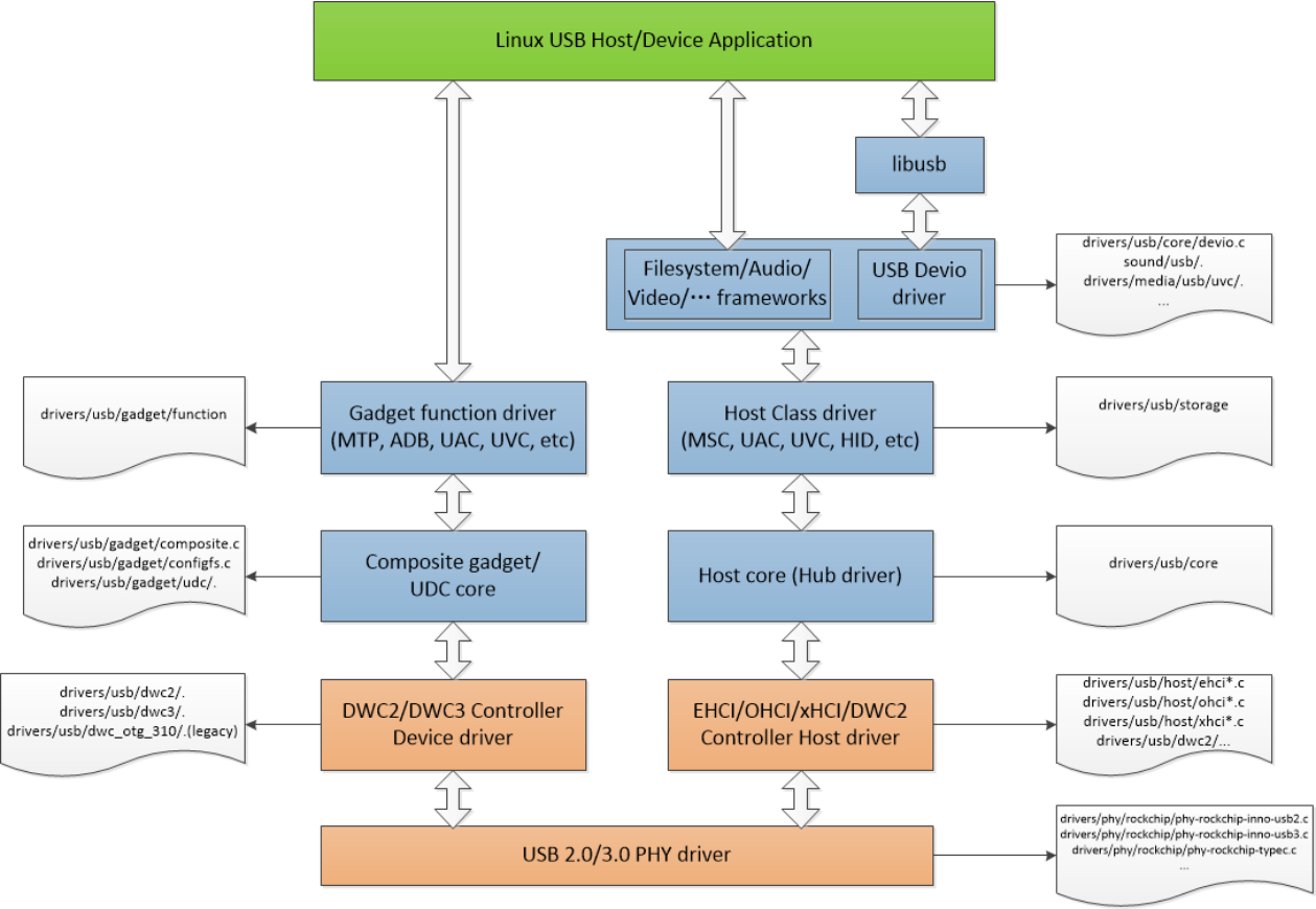
Abbildung 5-1. Linux-USB-Treiberarchitektur.
5.2 USB-PHY-Treiber
Hier wird der PHY-Code kurz erläutert. Hardwarearchitektur, Register und Signalanpassung stehen im Chip-TRM und in Rockchip_Introduction_USB_SQ_Tool_CN.
5.2.1 USB-2.0-PHY-Treiber
Rockchip nutzt Innosilicon und Synopsis USB 2.0 PHY. Unterschiedliche Hardware benötigt separate Treiber; SoCs mit identischem IP teilen hingegen einen Treiber statt eigener Treiber je SoC.
- Innosilicon-Treiber:
drivers/phy/phy-rockchip-inno-usb2.c. Synopsis nur für RK3188/RK3288:drivers/phy/rockchip/phy-rockchip-usb.c. Die meisten anderen SoCs verwenden Innosilicon, das im Folgenden behandelt wird.
- Innosilicon-USB-2.0-PHY-Funktionen:
- Vollständig USB-2.0-konform.
- 480/12/1.5Mbps.
- Alle USB-2.0-Testmodi.
- Ein oder zwei Ports pro PHY; zwei Ports kombinieren OTG und Host.
- OTG-Port mit Dual Role.
- Vollständige Battery-Charge-1.2-Unterstützung.
- rockchip_usb2phy_cfg steuert PHY-Register. Für einen neuen SoC mit Innosilicon-PHY wird hauptsächlich dessen rkxxxx_phy_cfgs ergänzt.
struct rockchip_usb2phy_cfg {
        unsigned int    reg;
        unsigned int    num_ports;
        int (*phy_tuning)(struct rockchip_usb2phy *);
        struct usb2phy_reg      clkout_ctl;
        const struct rockchip_usb2phy_port_cfg  port_cfgs[USB2PHY_NUM_PORTS];
        const struct rockchip_chg_det_reg       chg_det;
};
Felder von rockchip_usb2phy_cfg:
- reg: PHY-Offset im GRF, passend zu reg im DTS zur Zuordnung.
- num_ports: Portanzahl, bei OTG+Host gleich 2.
- phy_tuning: Signalanpassung wie Vorverzerrung und Amplitude.
- clkout_ctl: 480MHz-Ausgangstakt.
- port_cfgs: Portregisterkonfiguration.
- chg_det: Ladeerkennungsregister.
- Drei Works bedienen Zustandsautomaten:
- rockchip_chg_detect_work: Ladeerkennung für OTG Device.
- rockchip_usb2phy_otg_sm_work: OTG-Verbindungszustand und Suspend-Ein-/Austritt.
- rockchip_usb2phy_sm_work: Host-Verbindungszustand und Suspend-Ein-/Austritt.
An wichtigen Stellen protokolliert dev_dbg die Übergänge beim An-/Abstecken.
- Beispiel RK3399. Die Quellüberschrift nennt USB 3.0 PHY; beschrieben werden jedoch zwei unabhängige USB-2.0-PHYs mit je OTG und Host. OTG bildet gemeinsam mit Type-C-USB-3.0-PHY einen vollständigen Type-C-Anschluss; Host versorgt den USB-2.0-Host-Controller. Es folgt rk3399_phy_cfgs. port_cfgs steuert Suspend, VBUS, ID, DP-/DM-Pegel usw.; Feldbeschreibungen stehen in den Treiberkommentaren.
static const struct rockchip_usb2phy_cfg rk3399_phy_cfgs[] = {
        {
                .reg            = 0xe450,
                .num_ports      = 2,
                .phy_tuning     = rk3399_usb2phy_tuning,
                .clkout_ctl     = { 0xe450, 4, 4, 1, 0 },
                .port_cfgs      = {
                        [USB2PHY_PORT_OTG] = {
                                .phy_sus = { 0xe454, 8, 0, 0x052, 0x1d1 },
                                .bvalid_det_en  = { 0xe3c0, 3, 3, 0, 1 },
                                .bvalid_det_st  = { 0xe3e0, 3, 3, 0, 1 },
                                .bvalid_det_clr = { 0xe3d0, 3, 3, 0, 1 },
                                .bypass_dm_en   = { 0xe450, 2, 2, 0, 1 },
                                .bypass_sel     = { 0xe450, 3, 3, 0, 1 },
                                .idfall_det_en  = { 0xe3c0, 5, 5, 0, 1 },
                                .idfall_det_st  = { 0xe3e0, 5, 5, 0, 1 },
                                .idfall_det_clr = { 0xe3d0, 5, 5, 0, 1 },
                                .idrise_det_en  = { 0xe3c0, 4, 4, 0, 1 },
                                .idrise_det_st  = { 0xe3e0, 4, 4, 0, 1 },
                                .idrise_det_clr = { 0xe3d0, 4, 4, 0, 1 },
                                .ls_det_en      = { 0xe3c0, 2, 2, 0, 1 },
                                .ls_det_st      = { 0xe3e0, 2, 2, 0, 1 },
                                .ls_det_clr     = { 0xe3d0, 2, 2, 0, 1 },
                                .utmi_avalid    = { 0xe2ac, 7, 7, 0, 1 },
                                .utmi_bvalid    = { 0xe2ac, 12, 12, 0, 1 },
                                .utmi_iddig     = { 0xe2ac, 8, 8, 0, 1 },
                                .utmi_ls        = { 0xe2ac, 14, 13, 0, 1 },
                                .vbus_det_en    = { 0x449c, 15, 15, 1, 0 },
                },
                [USB2PHY_PORT_HOST] = {
                        .phy_sus        = { 0xe458, 1, 0, 0x2, 0x1 },
                        .ls_det_en      = { 0xe3c0, 6, 6, 0, 1 },
                        .ls_det_st      = { 0xe3e0, 6, 6, 0, 1 },
                        .ls_det_clr     = { 0xe3d0, 6, 6, 0, 1 },
                        .utmi_ls        = { 0xe2ac, 22, 21, 0, 1 },
                        .utmi_hstdet    = { 0xe2ac, 23, 23, 0, 1 }
                }
        },
        .chg_det = {
                .opmode         = { 0xe454, 3, 0, 5, 1 },
                .cp_det         = { 0xe2ac, 2, 2, 0, 1 },
                .dcp_det        = { 0xe2ac, 1, 1, 0, 1 },
                .dp_det         = { 0xe2ac, 0, 0, 0, 1 },
                .idm_sink_en    = { 0xe450, 8, 8, 0, 1 },
                .idp_sink_en    = { 0xe450, 7, 7, 0, 1 },
                .idp_src_en     = { 0xe450, 9, 9, 0, 1 },
                .rdm_pdwn_en    = { 0xe450, 10, 10, 0, 1 },
                .vdm_src_en     = { 0xe450, 12, 12, 0, 1 },
                .vdp_src_en     = { 0xe450, 11, 11, 0, 1 },
        },
},
{
        .reg            = 0xe460,
        .num_ports      = 2,
        .phy_tuning     = rk3399_usb2phy_tuning,
        .clkout_ctl     = { 0xe460, 4, 4, 1, 0 },
        .port_cfgs      = {
                [USB2PHY_PORT_OTG] = {
                        .phy_sus = { 0xe464, 8, 0, 0x052, 0x1d1 },
                        .bvalid_det_en  = { 0xe3c0, 8, 8, 0, 1 },
                        .bvalid_det_st  = { 0xe3e0, 8, 8, 0, 1 },
                        .bvalid_det_clr = { 0xe3d0, 8, 8, 0, 1 },
                        .idfall_det_en  = { 0xe3c0, 10, 10, 0, 1 },
                        .idfall_det_st  = { 0xe3e0, 10, 10, 0, 1 },
                        .idfall_det_clr = { 0xe3d0, 10, 10, 0, 1 },
                        .idrise_det_en  = { 0xe3c0, 9, 9, 0, 1 },
                        .idrise_det_st  = { 0xe3e0, 9, 9, 0, 1 },
                        .idrise_det_clr = { 0xe3d0, 9, 9, 0, 1 },
                        .ls_det_en      = { 0xe3c0, 7, 7, 0, 1 },
                        .ls_det_st      = { 0xe3e0, 7, 7, 0, 1 },
                        .ls_det_clr     = { 0xe3d0, 7, 7, 0, 1 },
                        .utmi_avalid    = { 0xe2ac, 10, 10, 0, 1 },
                        .utmi_bvalid    = { 0xe2ac, 16, 16, 0, 1 },
                        .utmi_iddig     = { 0xe2ac, 11, 11, 0, 1 },
                        .utmi_ls        = { 0xe2ac, 18, 17, 0, 1 },
                        .vbus_det_en    = { 0x451c, 15, 15, 1, 0 },
                },
                [USB2PHY_PORT_HOST] = {
                        .phy_sus        = { 0xe468, 1, 0, 0x2, 0x1 },
                        .ls_det_en      = { 0xe3c0, 11, 11, 0, 1 },
                        .ls_det_st      = { 0xe3e0, 11, 11, 0, 1 },
                                .ls_det_clr     = { 0xe3d0, 11, 11, 0, 1 },
                                .utmi_ls        = { 0xe2ac, 26, 25, 0, 1 },
                                .utmi_hstdet    = { 0xe2ac, 27, 27, 0, 1 }
                        }
                },
                .chg_det = {
                        .opmode         = { 0xe464, 3, 0, 5, 1 },
                        .cp_det         = { 0xe2ac, 5, 5, 0, 1 },
                        .dcp_det        = { 0xe2ac, 4, 4, 0, 1 },
                        .dp_det         = { 0xe2ac, 3, 3, 0, 1 },
                        .idm_sink_en    = { 0xe460, 8, 8, 0, 1 },
                        .idp_sink_en    = { 0xe460, 7, 7, 0, 1 },
                        .idp_src_en     = { 0xe460, 9, 9, 0, 1 },
                        .rdm_pdwn_en    = { 0xe460, 10, 10, 0, 1 },
                        .vdm_src_en     = { 0xe460, 12, 12, 0, 1 },
                        .vdp_src_en     = { 0xe460, 11, 11, 0, 1 },
                },
        },
        { /* sentinel */ }
};
- USB-2.0-PHY-Debugschnittstelle
/sys/devices/platform/[u2phy dev name] # ls
driver          extcon   of_node  phy   subsystem
driver_override modalias otg_mode power uevent
otg_mode wechselt Device/Host softwareseitig unabhängig von OTG ID. Erzwingen der Modi:
echo host > /sys/devices/platform/[u2phy dev name]/otg_mode
echo peripheral > /sys/devices/platform/[u2phy dev name]/otg_mode
echo otg > /sys/devices/platform/[u2phy dev name]/otg_mode
Kompatible Befehle aus Linux-3.10 und älter: 1 für Host, 2 für Device, 0 für OTG:
echo 1 > /sys/devices/platform/[u2phy dev name]/otg_mode
echo 2 > /sys/devices/platform/[u2phy dev name]/otg_mode
echo 0 > /sys/devices/platform/[u2phy dev name]/otg_mode
Hinweise:
- [u2phy dev name] durch den konkreten PHY-Knotennamen des SoC ersetzen.
- RV1126/RV1109 benötigen zusätzliche Schritte. Host: Device trennen, dann PHY umschalten:
echo disconnect > /sys/class/udc/ffd00000.dwc3/soft_connect
echo host > /sys/devices/platform/ff4c0000.usb2-phy/otg_mode
Device: PHY umschalten, dann Device verbinden:
echo peripheral > /sys/devices/platform/ff4c0000.usb2-phy/otg_mode
echo connect > /sys/class/udc/ffd00000.dwc3/soft_connect
OTG: PHY umschalten und Device verbinden:
echo otg > /sys/devices/platform/ff4c0000.usb2-phy/otg_mode
echo connect > /sys/class/udc/ffd00000.dwc3/soft_connect
5.2.2 USB-3.0-PHY-Treiber
Rockchip verwendet Type-C PHY, Innosilicon USB 3.0 PHY und Innosilicon USB 3.0 CombPhy mit unterschiedlichen Hardwaredesigns und separaten Treibern. Alle drei unterstützen nur SuperSpeed; für vollständiges USB 3.0 einschließlich High/Full/Low Speed ist zusätzlich USB-2.0-PHY nötig.
- Type-C PHY:
drivers/phy/rockchip/phy-rockchip-typec.c. RK3399 kombiniert USB 3.0 SuperSpeed und DisplayPort Transmit PHY. probe erstellt rockchip_dp_phy_ops für dp-port sowie rockchip_usb3_phy_ops für usb3-port getrennt; power_on/power_off und andere Operationen sind unabhängig. Vier Betriebsarten:
- Nur USB 3.0, etwa Type-C→Type-A-USB-3.0-Adapter.
- Nur DP, etwa DP-Kabel.
- USB 3.0 plus DP 2 lanes, etwa Type-C-Dongle.
- USB 2.0 plus DP 4 lanes, etwa Type-C-VR-Headset.
Ein CC-Chip erkennt den Kabeltyp; empfohlen wird FUSB302. Er meldet über extcon an den Type-C-PHY.
- rockchip_usb3_phy_power_on/power_off schalten den USB-3.0-PHY für den Controller ein/aus.
- tcphy_cfg_usb3_to_usb2_only erzwingt USB 2.0 only.
- tcphy_cfg_usb3_pll konfiguriert die USB-3.0-PLL.
- Innosilicon USB 3.0 PHY:
drivers/phy/rockchip/phy-rockchip-inno-usb3.c. RK3328 kombiniert USB-3.0- und USB-2.0-PHY. Funktionen:
- Serielle Übertragung mit 5.0Gb/s.
- 8-/16-/32-bit-Parallelschnittstelle für SuperSpeed-TX/RX.
- Integration schneller Komponenten in einen Funktionsblock.
- Daten- und Taktrückgewinnung aus dem seriellen Strom.
- Halteregister zur TX-/RX-Bereitstellung.
- Direkte Disparitätssteuerung für Compliance-Muster.
- 8b/10b-Codierung/Decodierung mit Fehleranzeige.
- Keine Erkennung abgetrennter Peripherie.
Besonderheit: Der Treiber implementiert USB-2.0- und USB-3.0-PHY-Operationen gemeinsam trotz unabhängiger Hardware. U3PHY_TYPE_UTMI und U3PHY_TYPE_PIPE sind die jeweiligen Indizes.
Funktionen:
- rockchip_u3phy_port_init(): USB-2.0-/3.0-Ports initialisieren.
- rockchip_u3phy_power_on(): Takt einschalten, USB2-PHY Normal und USB3-PHY P0.
- rockchip_u3phy_power_off(): USB2-PHY suspend, USB3-PHY P3 und Takt aus zur Verbrauchssenkung.
Weil der PHY USB-3.0-Trennung nicht erkennt, gibt es Zusatzfunktionen:
- rockchip_u3phy_on_disconnect(): Der HUB-Core erkennt die Trennung anhand linkstate und ruft den registrierten PHY-Notifier für Soft-Disconnect auf.
- rockchip_u3phy_on_shutdown(): DWC3 setzt damit den USB3-PHY beim Soft-Disconnect zurück.
- rockchip_u3phy_on_init(): DWC3 hebt am Ende dessen Reset auf.
USB 2.0 only erzwingen:
echo u2 > /sys/kernel/debug/[phy name]/u3phy_mode
USB 3.0/2.0 aktivieren, Standard nach Initialisierung:
echo u3 > /sys/kernel/debug/[phy name]/u3phy_mode
[phy name] durch den SoC-PHY-Knotennamen ersetzen.
- Innosilicon USB 3.0 CombPhy:
drivers/phy/rockchip/phy-rockchip-inno-combphy.c. RK1808 kombiniert USB-3.0-SuperSpeed- und PCIe-PHY; beide können nicht gleichzeitig arbeiten. rockchip_combphy_xlate() lässt USB-3.0-/PCIe-Treiber den erforderlichen Typ wählen. Für USB 3.0 im Controller-DTS phys setzen:
phys = <&u2phy_otg>, <&combphy PHY_TYPE_USB3>;
phy-names = "usb2-phy", "usb3-phy";
Für PCIe im Controller-DTS phys setzen:
phys = <&combphy PHY_TYPE_PCIE>;
phy-names = "pcie-phy";
USB-3.0-PHY unterstützt nur SuperSpeed und bildet mit dem USB-2.0-PHY-OTG-Port vollständiges USB 3.0/2.0/1.1/1.0. CombPhy-Funktionen:
- 5.0Gb/s Übertragung.
- 8-/16-/32-bit-Parallelschnittstelle für SuperSpeed-TX/RX.
- Integration schneller Komponenten in einen Funktionsblock.
- Daten-/Taktrückgewinnung.
- TX-/RX-Halteregister.
- Direkte Disparitätssteuerung für Compliance-Muster.
- 8b/10b-Codierung/Decodierung und Fehleranzeige.
Gemeinsame USB-3.0-/PCIe-phy_ops:
- rockchip_combphy_init: Referenztakt vorbereiten, PHY-Typ setzen, Register initialisieren.
- rockchip_combphy_exit: Taktvorbereitung zurücknehmen.
- rockchip_combphy_power_on/power_off: USB-3.0-PHY-Block ein-/ausschalten.
Weitere Funktionen:
- rk1808_combphy_low_power_control: Stromsparsteuerung bei Deepsleep.
- u3phy_mode_store/u3phy_mode_show: USB 2.0 only über sysfs u3phy_mode. Beim dynamischen Wechsel USB 2.0 only↔USB 2.0/3.0 muss xHCI neu initialisiert werden; sysfs otg_mode entfernt/ergänzt dazu xHCI HCD.
#1. Default is USB 3.0 OTG mode, config to USB 2.0 only mode
   echo u2 > /sys/devices/platform/[u3phy dev name]/u3phy_mode
   echo host > /sys/devices/platform/[u2phy dev name]/otg_mode

#2. Default is USB 3.0 Host mode, config to USB 2.0 only mode
   echo otg > /sys/devices/platform/[u2phy dev name]/otg_mode
   echo u2 > /sys/devices/platform/[u3phy dev name]/u3phy_mode
   echo host > /sys/devices/platform/[u2phy dev name]/otg_mode

#3. Default is USB 2.0 only Host mode, config to USB 3.0 mode
   echo otg > /sys/devices/platform/[u2phy dev name]/otg_mode
   echo u3 > /sys/devices/platform/[u3phy dev name]/u3phy_mode
   echo host > /sys/devices/platform/[u2phy dev name]/otg_mode
[u3phy dev name] und [u2phy dev name] durch die SoC-PHY-Namen ersetzen. Der Standardmodus wird durch dr_mode im DWC3-DTS festgelegt.
5.3 USB-Controllertreiber
5.3.1 USB-2.0-OTG-Treiber
5.3.1.1 USB-2.0-OTG-Architektur
USB 2.0 OTG nutzt DWC2, siehe Abbildung 5-2. AHB-Master/-Slave dienen dem internen DMA zwischen USB-FIFO und Speicher über AHB. Grüne Blöcke sind optionale IP-Funktionen; Rockchip-DWC2 unterstützt weder externes DMA noch endp_multi_proc_interrupt. Die PHY-Schnittstelle ist UTMI+.
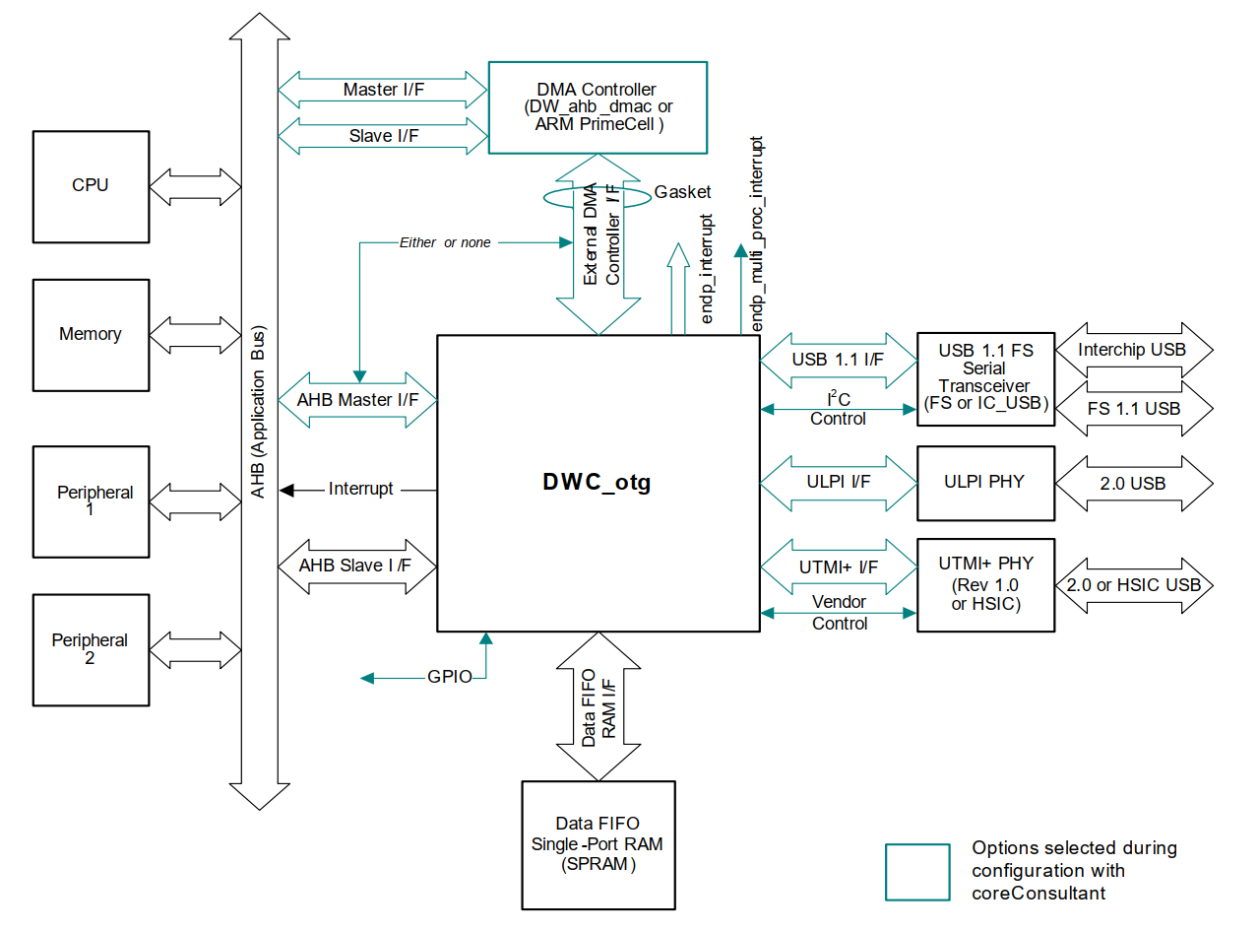
Abbildung 5-2. DWC2-Systemblockdiagramm. Abbildung 5-3 zeigt Device-, Host- und OTG-Interrupts samt Unterinterrupts; alle werden über ein gemeinsames Signal zur Interruptlogik des Chips geführt.
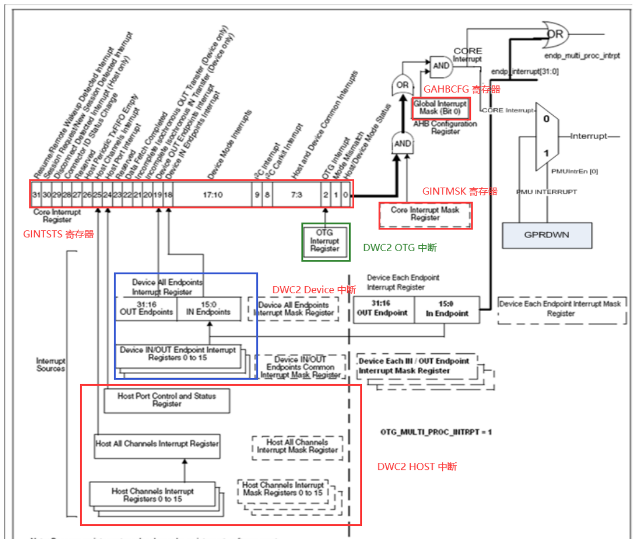
Abbildung 5-3. DWC2-Interrupthierarchie.
5.3.1.2 USB-2.0-OTG-Treiberüberblick
- DWC2-Treiber:
drivers/usb/dwc2/*: die meisten SoCs.drivers/usb/dwc_otg_310/*: älterer Treiber nur für RK3288/RK3368.
- Ab Linux-4.19 nutzen alle SoCs dwc2 statt dwc_otg_310; daher wird hier dwc2 behandelt.
USB OTG 2.0 ist Dual Role mit Host/Device, entspricht dem OTG Supplement to USB2.0 und unterstützt 480Mbps High Speed, 12Mbps Full Speed und 1.5Mbps Low Speed. Codeaufbau:
~/src/android_Q/kernel/drivers/usb/dwc2$ tree .
├── core.c (dwc2 core reset, configure core param and other general operations)
├── core.h
├── core_intr.c (dwc2 general interrupt events, including otg intr, id intr, wakeup intr,
etc.)
├── debugfs.c (dwc2 debug interface, such as printing register information)
├── debug.h
├── gadget.c (all tasks related to dwc2 gadget mode, such as gadget initialization, gadget
interrupt event)
├── hcd.c (dwc2 host mode related tasks and core init, phy init, device/host mode switching)
├── hcd_ddma.c (dwc2 descriptor DMA related tasks)
├── hcd.h
├── hcd_intr.c (handling of all interrupt events in dwc2 host mode)
├── hcd_queue.c (dwc2 host mode transmission queue processing)
├── hw.h
├── Kconfig
├── Makefile
├── pci.c (initialization of pci bus interface, Rockchip dwc2 uses AHB bus)
└── platform.c (implement dwc2 probe, initialize dwc2 lowlevel hw resources according to
core_params configuration of different chips)
5.3.1.3 USB-2.0-OTG-Debugschnittstelle
DWC2-Beispiel RK3328:
rk3328_box:/sys/kernel/debug/ff580000.usb # ls
ep0   ep2out ep4out ep6out ep8in  ep9in  fifo    state
ep1in ep3in  ep5in  ep7in  ep8out ep9out regdump testmode
- ep*in/out: Zustand jedes verfügbaren Endpunkts.
- fifo: Gesamt-FIFO und periodische TX-FIFOs.
- state: Hardwarezustand und allgemeine Endpunktinformationen.
- regdump: Core-Register.
- testmode: USB-Testmodus ändern.
DWC_OTG_310-Beispiel RK3288:
rk3288:/sys/devices/platform/ff580000.usb # ls
busconnected  fr_interval gsnpsid   modalias       regoffset     uevent
buspower      gadget      guid      mode           regvalue      usb5
bussuspend    ggpio       gusbcfg   mode_ch_tim_en remote_wakeup wr_reg_test
devspeed      gnptxfsiz   hcd_frrem pools          spramdump
disconnect_us gotgctl     hcddump   power          subsystem
driver        gpvndctl    hprt0     rd_reg_test    test_sq
enumspeed     grxfsiz     hptxfsiz  regdump        udc

rk3328_box:/sys/devices/platform/ff580000.usb/driver # ls
bind       dwc_otg_conn_en force_usb_mode uevent vbus_status
debuglevel ff580000.usb    op_state       unbind versio
- busconnected: Core Control Status Register lesen/schreiben.
- fr_interval: HFIR Frame Interval lesen; Schreiben lädt HFIR während des Betriebs neu, erst nach gesetztem HPRT.PrtEnaPort.
- gsnpsid: Synopsys ID Register.
- regoffset: Offset des nächsten Registerzugriffs.
- buspower: Busversorgung, 0 aus/1 an.
- guid: User ID Register.
- regvalue: Registerwert am regoffset.
- bussuspend: USB-Bus suspendieren.
- ggpio: untere 16 Bit des General Purpose IO Register lesen oder obere 16 Bit schreiben.
- gusbcfg: Core USB Configuration Register.
- mode_ch_tim_en: nach Resume 200 PHY-Takte warten, bevor opmode nach Suspend/LPM auf 00 wechselt.
- remote_wakeup: Status lesen; Schreiben initiiert Host-Wakeup. Bei Bit 0=1 und aktivierter Funktion wird das Remote-Wakeup-Signal im Device Control Register für 1ms gesetzt.
- wr_reg_test: Dauer wiederholter GNPTXFSIZ-Schreibzugriffe einschließlich Anzahl.
- devspeed: Device-Geschwindigkeit in DCFG.
- gnptxfsiz: Non-periodic Transmit Size Register.
- spramdump: Core-Registerinhalt.
- disconnect_us: disconnect_device_us lesen; Schreiben löst 100us Soft-Disconnect aus, nur Device.
- gotgctl: Core Control Status Register.
- hcddump: aktueller HCD-Zustand.
- gpvndctl: PHY Vendor Control Register.
- hprt0: Host Port Control and Status Register.
- rd_reg_test: Dauer und Anzahl wiederholter GNPTXFSIZ-Lesezugriffe.
- test_sq: Nutzung des test_sq-Attributs.
- enumspeed: Enumerationsgeschwindigkeit.
- grxfsiz: Receive FIFO Size Register.
- hptxfsiz: Host Periodic Transmit FIFO.
- regdump: Core-Register.
- dwc_otg_conn_en: PC-Verbindung im Device-Modus ein/aus.
- force_usb_mode: 0 Normal, 1 Host, 2 Device.
- vbus_status: VBUS-Spannung.
- debuglevel: Debugstufe.
- op_state: Softwarezustand; bei a_host→a_peripherial und b_device→b_host eventuell vom Core abweichend, damit Übergänge erkennbar bleiben.
- version: Treiberversion.
5.3.2 USB-2.0-Host-Treiber
5.3.2.1 USB-2.0-Host-Architektur
Der Controller kombiniert USB-2.0-EHCI mit USB-1.1-OHCI. Grüne Blöcke in Abbildung 5-4 sind optionale IP-Funktionen. Rockchip nutzt einen EHCI und einen OHCI über UTMI+ zum PHY. Beide greifen per internem DMA über AHB auf Speicher zu. EHCI verarbeitet High Speed, OHCI Full/Low Speed.
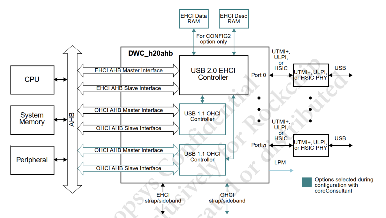
Abbildung 5-4. EHCI-/OHCI-Systemblockdiagramm.
5.3.2.2 USB-2.0-Host-Treiberüberblick
- Code:
drivers/usb/host/ehci*: USB 2.0 Host.
drivers/usb/host/ohci*: USB 1.1/1.0 Host.
- EHCI-Codeaufbau folgt unten. Nicht aufgeführte Dateien wie ehci-exynos.c sind herstellerspezifische Plattformtreiber. Rockchip entspricht dem EHCI-Standard und verwendet ehci-platform.c.
~/src/android_Q/kernel/drivers/usb/host$ tree
├── ehci-dbg.c (ehci debugfs debugging interface, such as printing ehci register
information)
├── ehci.h
├── ehci-hcd.c (Initialization of ehci controller, interrupt event processing, urb queue
management, etc.)
├── ehci-hub.c (control and status query of ehci root hub, bus suspend/resume)
├── ehci-mem.c (allocation and initialization of ehci mem, allocation and initialization of
qtd/qh resources)
├── ehci-pci.c (Initialization of pci bus interface, Rockchip ehci uses AHB bus, does not
use this driver)
├── ehci-platform.c (ehci universal platform driver, implement ehci probe, register ehci hcd
with usb bus, enable ehci controller)
├── ehci-q.c (processing of ehci qtd/qh transmission queue)
├── ehci-sched.c (cyclic transmission scheduling processing of ehci interrupt, iso, split
iso)
├── ehci-sysfs.c (ehci sysfs debugging interface, display companion controller, display
uframe_periodic_max)
├── ehci-timer.c (task processing related to ehci timer)
Wichtige EHCI-Strukturen:
static const struct hc_driver ehci_hc_driver = {
    .description =      hcd_name,
    .product_desc =     "EHCI Host Controller",
    .hcd_priv_size =    sizeof(struct ehci_hcd),
    /*
     * generic hardware linkage
     */
    .irq =          ehci_irq,
    .flags =        HCD_MEMORY | HCD_USB2 | HCD_BH,
    /*
     * basic lifecycle operations
     */
    .reset =        ehci_setup,
    .start =        ehci_run,
    .stop =         ehci_stop,
    .shutdown =     ehci_shutdown,
    /*
     * managing i/o requests and associated device resources
     */
    .urb_enqueue =      ehci_urb_enqueue,
    .urb_dequeue =      ehci_urb_dequeue,
    .endpoint_disable = ehci_endpoint_disable,
    .endpoint_reset =   ehci_endpoint_reset,
    .clear_tt_buffer_complete = ehci_clear_tt_buffer_complete,
    /*
     * scheduling support
     */
    .get_frame_number = ehci_get_frame,
    /*
     * root hub support
     */
    .hub_status_data =  ehci_hub_status_data,
    .hub_control =      ehci_hub_control,
    .bus_suspend =      ehci_bus_suspend,
    .bus_resume =       ehci_bus_resume,
    .relinquish_port =  ehci_relinquish_port,
    .port_handed_over = ehci_port_handed_over,
    /*
     * device support
     */
    .free_dev =     ehci_remove_device,
};
Es folgt der OHCI-Codeaufbau. Nicht aufgeführte Dateien wie ohci-exynos.c sind Herstellerplattformen. Rockchip entspricht dem OHCI-Standard und nutzt ohci-platform.c.
~/src/android_Q/kernel/drivers/usb/host$ tree
├── ohci-dbg.c (ohci debugfs debugging interface, such as printing ohci register
information)
├── ohci.h
├── ohci-hcd.c (initialization of ohci controller, interrupt event processing, urb queue
management, etc.)
├── ohci-hub.c (control and status query of ohci root hub, bus suspend/resume)
├── ohci-mem.c (allocation and initialization of ohci mem, allocation and initialization of
td/ed resources)
├── ohci-pci.c (Initialization of pci bus interface, Rockchip ohci uses AHB bus, does not
use this driver file)
├── ohci-platform.c (ohci universal platform driver, implement ohci probe, register ohci hcd
with usb bus, enable ohci controller)
├── ohci-q.c (handling of ohci td/ed transmission queue)
Wichtige OHCI-Strukturen:
static const struct hc_driver ohci_hc_driver = {
    .description =          hcd_name,
    .product_desc =         "OHCI Host Controller",
    .hcd_priv_size =        sizeof(struct ohci_hcd),
    /*
     * generic hardware linkage
    */
    .irq =                  ohci_irq,
    .flags =                HCD_MEMORY | HCD_USB11,
    /*
    * basic lifecycle operations
    */
    .reset =                ohci_setup,
    .start =                ohci_start,
    .stop =                 ohci_stop,
    .shutdown =             ohci_shutdown,
    /*
     * managing i/o requests and associated device resources
    */
    .urb_enqueue =          ohci_urb_enqueue,
    .urb_dequeue =          ohci_urb_dequeue,
    .endpoint_disable =     ohci_endpoint_disable,
    /*
    * scheduling support
    */
    .get_frame_number =     ohci_get_frame,
    /*
    * root hub support
    */
    .hub_status_data =      ohci_hub_status_data,
    .hub_control =          ohci_hub_control,
#ifdef CONFIG_PM
    .bus_suspend =          ohci_bus_suspend,
    .bus_resume =           ohci_bus_resume,
#endif
    .start_port_reset = ohci_start_port_reset,
};
5.3.2.3 USB-2.0-Host-Debugschnittstelle
Beispiel RK3399 EHCI/OHCI. Für EHCI CONFIG_DYNAMIC_DEBUG aktivieren.
rk3399_box:/sys/kernel/debug/usb/ehci/fe380000.usb # ls
async bandwidth periodic registers

rk3399:/sys/devices/platform/fe380000.usb # ls
companion driver_override of_node power     uevent              usb5
driver    modalias        pools   subsystem uframe_periodic_max usbmon
- async: Momentaufnahme des Async Schedule.
- bandwidth: HS-Bandbreitentabelle.
- periodic: Momentaufnahme des Periodic Schedule.
- registers: Capability Registers, Interruptparameter und Operational Registers.
- companion: EHCI-Begleitcontroller.
- uframe_periodic_max: maximal nutzbare Mikroframe-Bandbreite periodischer Übertragung, standardmäßig 100μs, maximal 125μs.
OHCI-Debugschnittstelle benötigt CONFIG_DYNAMIC_DEBUG.
rk3399_box:/sys/kernel/debug/usb/ohci/fe3a0000.usb # ls
async periodic registers
- async: Control- und Bulk-Listen zusammen.
- periodic: periodischer Zeitplan einschließlich Last.
- registers: Treiberinformationen, Register in Spezifikationsreihenfolge und weitere Frame-Timing-Register.
5.3.3 USB-3.0-OTG-Treiber
5.3.3.1 USB-3.0-OTG-Architektur
USB 3.0 OTG verwendet DWC3, siehe Abbildung 5-5.
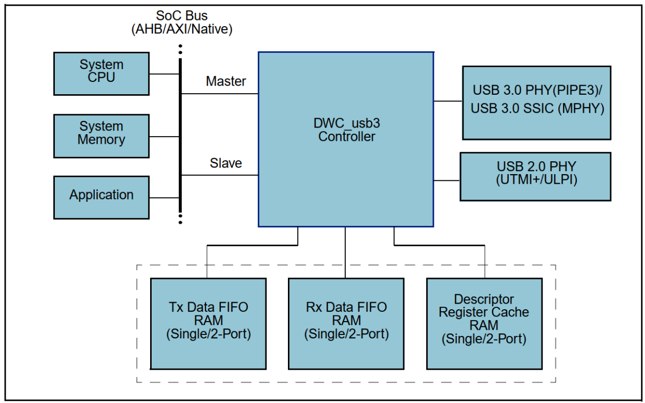
Abbildung 5-5. DWC3-Systemblockdiagramm. Synopsys DesignWare Core USB 3.0 enthält xHCI Host. Möglich sind statischer Host/Device, USB-2.0-/3.0-OTG-A/B anhand USB2-PHY-ID sowie DFP/UFP/Data Role Swap nach Type-C. Übertragung erfolgt mit Super/High/Full/Low Speed. Merkmale:
- USB 3.0/2.0/1.1/1.0.
- Integrierter xHCI Host.
- Nur DRD, kein vollständiges OTG-Protokoll.
- Host und Device nicht gleichzeitig.
- Host-USB2-/USB3-Ports gleichzeitig unabhängig nutzbar.
- Device-USB2-/USB3-Ports nicht gleichzeitig unabhängig nutzbar.
- Nur DMA, kein Slave-Modus.
- SRAM/DRAM erforderlich.
xHCI ist ein standardmäßiger USB-3.0-Host wie am PC und unterstützt erzwungenes USB 2.0 only.
5.3.3.2 USB-3.0-OTG-Treiberüberblick
- Code:
drivers/usb/dwc3/*: gemeinsamer OTG-Core und Peripheral.
drivers/usb/host/xhci*: USB 3.0 Host.
- Linux-4.19 aktualisiert DWC3 erheblich gegenüber 4.4, behält jedoch die grundlegende Dateistruktur:
- drd.c für dynamischen Dual-Role-Wechsel ergänzt.
- dwc3-rockchip.c durch dwc3-of-simple.c ersetzt.
- dwc3-rockchip-inno.c für RK3328/RK3228H beibehalten.
DWC3-/xHCI-Struktur in Linux-4.19:
~/src/kernel-4.19/drivers/usb/dwc3$ tree .
├── core.c (implementation of dwc3 core probe, allocate various resources, initialize
controller, PM runtime management)
├── core.h
├── debugfs.c (implementation of dwc3 debugfs debug interface)
├── debug.h
├── drd.c (dwc3 drd/otg mode dynamic switching processing)
├── dwc3-of-simple.c (dwc3 universal platform driver, realize the first level
dwc3_of_simple_probe of dwc3, and call the second level dwc3_probe of dwc3 core through
of_platform_populate)
├── dwc3-pci.c (Initialization of pci bus interface, Rockchip dwc3 uses AXI bus, does not
use this driver file)
├── dwc3-rockchip-inno.c (glue layer for RK3328/RK3228H, increase the realization of
disconnect work)
├── ep0.c (task processing of dwc3 gadget ep0)
├── gadget.c (dwc3 gadget endpoint task processing except ep0, interrupt entry function
implementation)
├── gadget.h
├── host.c (dwc3 host resource allocation, and call xhci_plat_probe of xHCI through
platform_device_add)
├── io.h
├── Kconfig
├── Makefile
├── trace.c (Dwc3 trace implementation, Linux-based trace interface)
├── trace.h
└── ulpi.c (code implementation of ulpi phy interface, Rockchip dwc3 does not use ulpi)

~/src/kernel-4.19/drivers/usb/host$ tree
├── xhci.c (initialize xhci_hc_driver, start xHCI controller, manage urb queue, etc.)
├── xhci-dbg.c (realize debug function for printing log)
├── xhci-dbgcap.c (xHCI hardware module debug capability function is not supported by
Rockchip)
├── xhci-dbgcap.h
├── xhci-debugfs.c (xHCI debugfs debugging interface)
├── xhci-debugfs.h
├── xhci-ext-caps.c (xHCI extended capability function implementation, not supported by
Rockchip)
├── xhci-ext-caps.h
├── xhci.h
├── xhci-hub.c (xHCI root hub control and status query, bus suspend/resume)
├── xhci-mem.c (xHCI mem management, including allocation, initialization, release and other
operations)
├── xhci-pci.c (Initialization of pci bus interface, Rockchip xHCI uses AXI bus, does not
use this driver file)
├── xhci-plat.c (xHCI universal platform driver, implement xhci_plat_probe, Rockchip uses
this driver)
├── xhci-plat.h
├── xhci-ring.c (management of xHCI transfer/command/event ring)
├── xhci-trace.c (xHCI trace implementation, Linux-based trace interface)
└── xhci-trace.h
Wichtige Gadget-Strukturen:
static const struct usb_gadget_ops dwc3_gadget_ops = {
    .get_frame      = dwc3_gadget_get_frame,
    .wakeup         = dwc3_gadget_wakeup,
    .set_selfpowered    = dwc3_gadget_set_selfpowered,
    .pullup         = dwc3_gadget_pullup,
    .udc_start      = dwc3_gadget_start,
    .udc_stop       = dwc3_gadget_stop,
};
Wichtige Host-Strukturen:
static const struct hc_driver xhci_hc_driver = {
    .description =      "xhci-hcd",
    .product_desc =     "xHCI Host Controller",
    .hcd_priv_size =    sizeof(struct xhci_hcd *),
    /*
     * generic hardware linkage
     */
    .irq =          xhci_irq,
    .flags =        HCD_MEMORY | HCD_USB3 | HCD_SHARED,
    /*
     * basic lifecycle operations
     */
    .reset =        NULL, /* set in xhci_init_driver() */
    .start =        xhci_run,
    .stop =         xhci_stop,
    .shutdown =     xhci_shutdown,
    /*
     * managing i/o requests and associated device resources
     */
    .urb_enqueue =      xhci_urb_enqueue,
    .urb_dequeue =      xhci_urb_dequeue,
    .alloc_dev =        xhci_alloc_dev,
    .free_dev =     xhci_free_dev,
    .alloc_streams =    xhci_alloc_streams,
    .free_streams =     xhci_free_streams,
    .add_endpoint =     xhci_add_endpoint,
    .drop_endpoint =    xhci_drop_endpoint,
    .endpoint_reset =   xhci_endpoint_reset,
    .check_bandwidth =  xhci_check_bandwidth,
    .reset_bandwidth =  xhci_reset_bandwidth,
    .address_device =   xhci_address_device,
    .enable_device =    xhci_enable_device,
    .update_hub_device =    xhci_update_hub_device,
    .reset_device =     xhci_discover_or_reset_device,
    /*
     * scheduling support
     */
    .get_frame_number = xhci_get_frame,
    /*
     * root hub support
     */
    .hub_control =      xhci_hub_control,
    .hub_status_data =  xhci_hub_status_data,
    .bus_suspend =      xhci_bus_suspend,
    .bus_resume =       xhci_bus_resume,
    /*
     * call back when device connected and addressed
     */
    .update_device =        xhci_update_device,
    .set_usb2_hw_lpm =  xhci_set_usb2_hardware_lpm,
    .enable_usb3_lpm_timeout =  xhci_enable_usb3_lpm_timeout,
    .disable_usb3_lpm_timeout = xhci_disable_usb3_lpm_timeout,
    .find_raw_port_number = xhci_find_raw_port_number,
};
5.3.3.3 USB-3.0-OTG-Debugschnittstelle
Beispiel Linux-4.19 RK3399 USB 3.0 OTG0:
console:/sys/kernel/debug/fe800000.dwc3 # ls
ep0in  ep1in  ep2in  ep3in  ep4in  ep5in  ep6out     lsp_dump regdump
ep0out ep1out ep2out ep3out ep4out ep5out link_state mode     testmode

console:/sys/kernel/debug/fe800000.dwc3/ep0in # ls
descriptor_fetch_queue rx_info_queue    trb_ring
event_queue            rx_request_queue tx_fifo_queue
rx_fifo_queue          transfer_type    tx_request_queue

console:/sys/kernel/debug/usb/xhci/xhci-hcd.0.auto # ls
command-ring ports          reg-ext-legsup:00   reg-op
devices      reg-cap        reg-ext-protocol:00 reg-runtime
event-ring   reg-ext-dbc:00 reg-ext-protocol:01
Debugknoten:
- mode: dr_mode lesen/schreiben.
- testmode: High-Speed-Test für Augendiagramme.
- link_state: Linkzustand lesen/schreiben.
- regdump: DWC3-Register.
- ep*in/out: Endpunkt-Debugverzeichnis.
- descriptor_fetch_queue: freier DescFetchQ-Platz.
- rx_info_queue: freier RXInfoQ-Platz.
- trb_ring: TRB-Pool.
- event_queue: freier EventQ-Platz.
- rx_request_queue: freier RxReqQ-Platz.
- tx_fifo_queue: freier TxFIFO-Platz.
- rx_fifo_queue: freier RxFIFO-Platz.
- transfer_type: Endpunkt-Übertragungstyp.
- tx_request_queue: freier TxReqQ-Platz.
- command-ring: xHCI-Command-Ring-Zustand.
- event-ring: xHCI-Event-Ring-Zustand.
- reg-op: xHCI-Registerzustand.
USB-3.0-OTG-Tracepoints:
sys/kernel/debug/tracing/events/xhci-hcd
sys/kernel/debug/tracing/events/dwc3
Details: sys/kernel/debug/tracing/README.
Softwarebefehle erzwingen Host/Device unabhängig von der USB-Schaltung. Alte Linux-4.4-Befehle nur für RK3399:
#RK3399 Type-C0 USB OTG switch command
#1.Force host mode
  echo host > sys/kernel/debug/usb@fe800000/rk_usb_force_mode
#2.Force peripheral mode
  echo peripheral > sys/kernel/debug/usb@fe800000/rk_usb_force_mode
Neue Linux-4.4-Befehle nur für RK3399/RK1808:
#RK3399 Type-C0 USB OTG switch command
#1.Force host mode
  echo host > sys/devices/platform/usb0/dwc3_mode
#2.Force peripheral mode
  echo peripheral > sys/devices/platform/usb0/dwc3_mode

#RK1808 USB OTG switch command
#1.Force host mode
  echo host > sys/devices/platform/usb/dwc3_mode
#2.Force peripheral mode
  echo peripheral > sys/devices/platform/usb/dwc3_mode
Linux-4.19-Befehle für alle DWC3-SoCs:
#RK3399 Type-C0 USB OTG switch command
#1.Force host mode
  echo host > sys/devices/platform/ff770000.syscon/ff770000.syscon:usb2-phy@e450/otg_mode
#2.Force peripheral mode
  echo peripheral > sys/devices/platform/ff770000.syscon/ff770000.syscon:usb2-
phy@e450/otg_mode

#For other SoCs, the method is similar, just search for the "otg_mode" node under the
sys/devices/platform path, and then set the node.
Linux-5.10-Befehle für alle DWC3-SoCs:
#RK3588 Type-C0 USB OTG switch command
#Method1. [Legacy] use usb phy node
#1.Force host mode
  echo host > /sys/devices/platform/fd5d0000.syscon/fd5d0000.syscon:usb2-phy@0/otg_mode
#2.Force peripheral mode
  echo peripheral > /sys/devices/platform/fd5d0000.syscon/fd5d0000.syscon:usb2-
phy@0/otg_mode

#Method2.[New] use usb controller node
#1.Force host mode
  echo host > /sys/kernel/debug/usb/fc000000.usb/mode
#2.Force peripheral mode
  echo device > /sys/kernel/debug/usb/fc000000.usb/mode

#For other SoCs, the method is similar, just search for the "otg_mode" or "mode" node under
the sys path, and then set the node.
5.4 USB-GPIO-Treiber und Softwareablauf
Linux unterstützt folgende USB-GPIO-Treiber:
- usb-conn-gpio:
Documentation/devicetree/bindings/connector/usb-connector.yaml
drivers/usb/common/usb-conn-gpio.c
Verarbeitet VBUS-/ID-GPIO-Interrupts, setzt Device/Host über usb_role_switch und unterstützt SDP-Laderollenmeldungen.
- extcon-usb-gpio:
Documentation/devicetree/bindings/extcon/extcon-usb-gpio.txt
drivers/extcon/extcon-usb-gpio.c
Verarbeitet VBUS-/ID-GPIO-Interrupts und setzt EXTCON_USB/EXTCON_USB_HOST durch extcon-Ereignisse.
drivers/usb/phy/phy-gpio-vbus-usb.cverwaltet VBUS-Regler und Gadget-Verbindung anhand VBUS über usb_gadget_vbus_connect/usb_gadget_vbus_disconnect. Das Rockchip-SDK nutzt extcon-usb-gpio.c zur extcon-Kommunikation mit PHY/Controller für Device-Hotplug und OTG-Rollenwechsel.
5.4.1 VBUSDET-GPIO-Softwareablauf
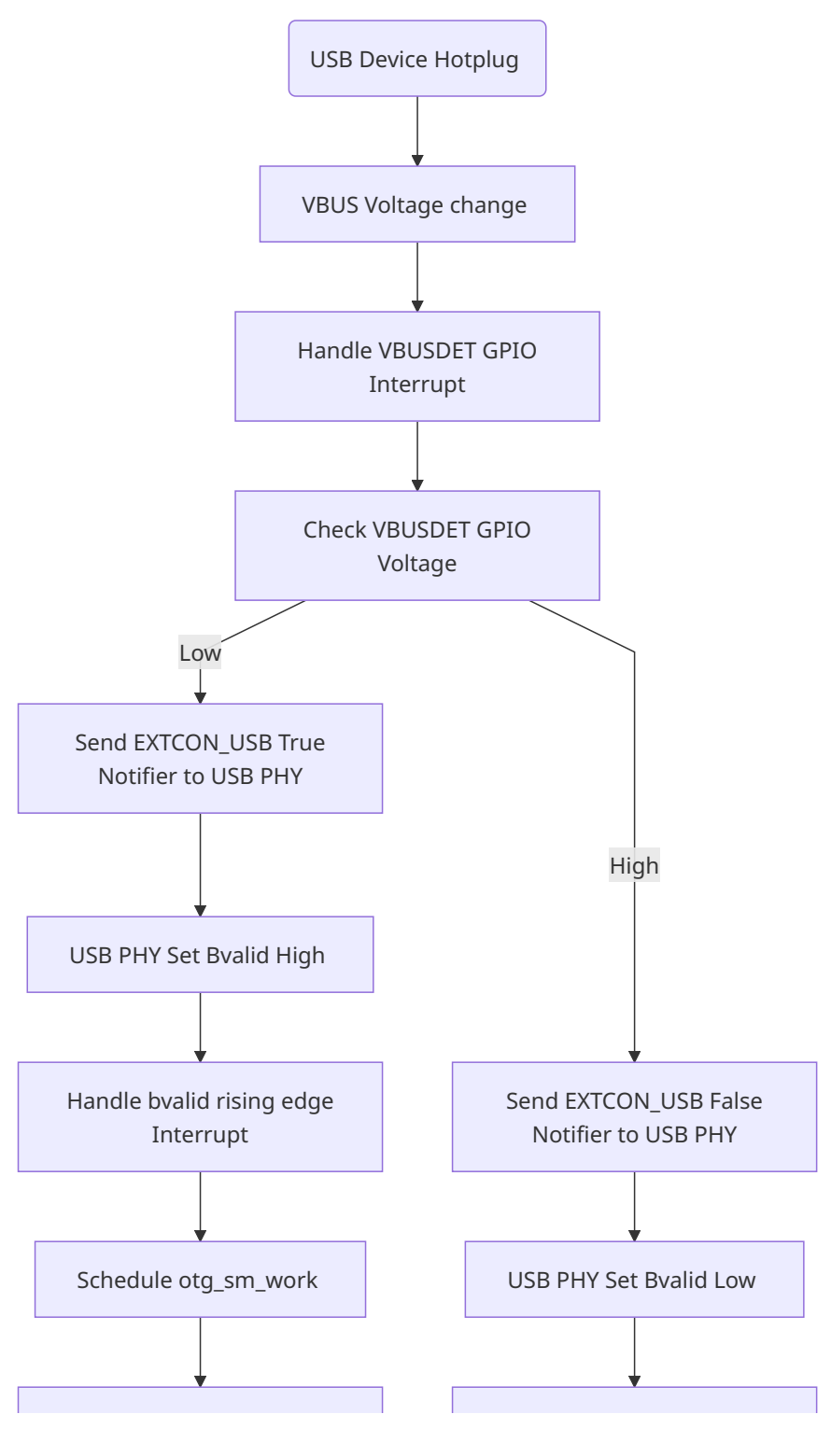
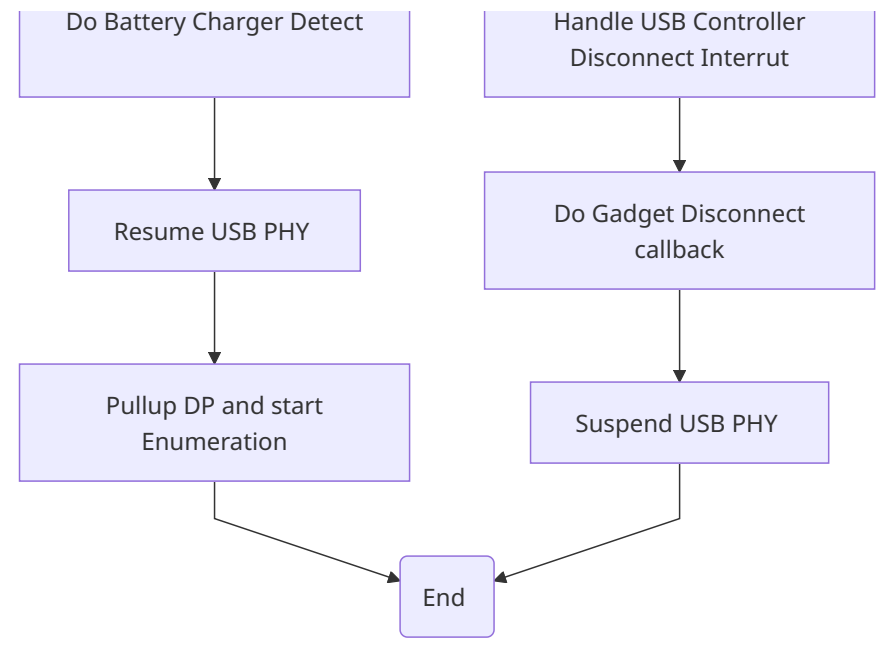
Bei RK3506G EVB1 invertiert ein Transistor zwischen Anschluss-VBUS und VBUSDET GPIO den Pegel. Device-Hotplug-Ablauf:
- PC-Verbindung: VBUS Low→High → GPIO-Interrupt → Handler erkennt GPIO Low → extcon an USB2-PHY → rockchip_usb2phy_usb_bvalid_enable() setzt GRF bvalid High → Bvalid-Flankeninterrupt → rockchip_usb2phy_bvalid_irq ruft otg_sm_work auf → Ladeerkennung und PHY-Resume → DP-Pull-up und Enumeration.
- Trennung: VBUS High→Low → GPIO-Interrupt → Handler erkennt GPIO High → extcon an PHY → rockchip_usb2phy_usb_bvalid_enable() setzt Bvalid Low und löst DWC2-Device-Disconnect aus → otg_sm_work pollt GRF Bvalid, erkennt Low → PHY-Suspend.
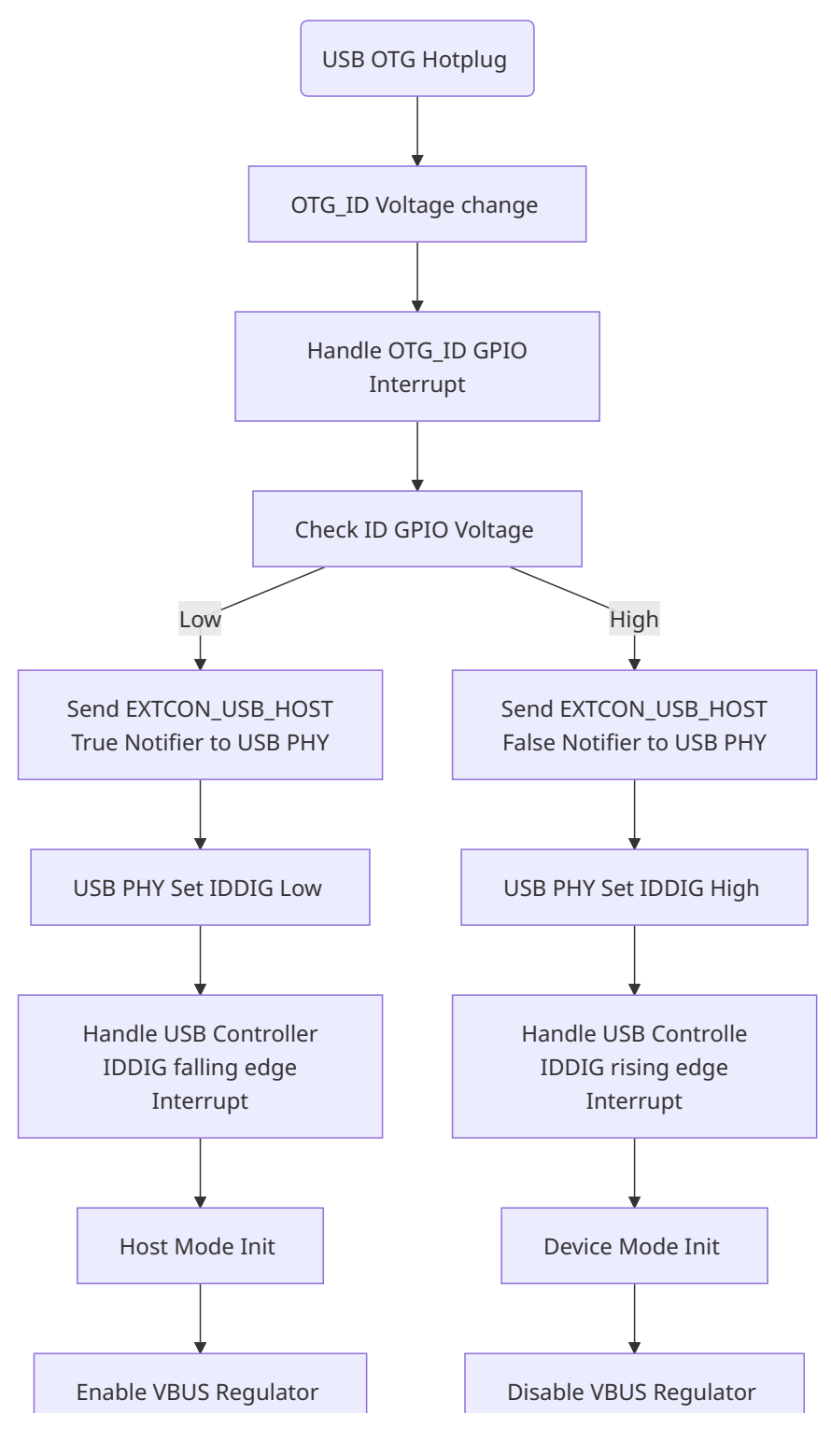
5.4.2 OTG_ID-GPIO-Softwareablauf
- OTG-Kabel einstecken: ID High→Low → GPIO-Interrupt → Handler erkennt Low → extcon an PHY → GRF IDDIG Low → DWC2-ID-Interrupt → Host-Initialisierung.
- Kabel entfernen: ID Low→High → GPIO-Interrupt → Handler erkennt High → extcon an PHY → GRF IDDIG High → DWC2-ID-Interrupt → Device-Initialisierung.

6. Android-USB-Gadget-Konfiguration
6.1 USB Gadget Configfs
Seit Linux-3.11 werden Gadgets über Configfs konfiguriert; android.c wurde aus dem Gadget-Verzeichnis entfernt. Configfs-fähige Klassentreiber liegen unter drivers/usb/gadget/function. Dokumentation:
Documentation/ABI/testing/configfs-usb-gadget-xxxx.txtDocumentation/filesystems/configfs/configfs.txtDocumentation/usb/gadget_configfs.txtDocumentation/usb/gadget-testing.txt- Kernel USB Gadget Configfs Interface
- TIZEN USB
- https://wiki.linaro.org/LMG/Kernel/AndroidConfigFSGadgets
6.2 Gadget-Konfigurationsdateien
Android-USB-Skripte:
init.usb.rc
init.usb.configfs.rc
init.rk30board.usb.rc
fstab.rk30board.bootmode.emmc
- init.usb.rc: Android-Standard-RC, keine Änderung nötig.
- fstab.rk30board.bootmode.emmc: Mountpfade für SD/USB. Rockchip-Vold kann USB-Mountpfade automatisch mit Wildcards suchen und zuordnen.
# for USB 2.0
/devices/platform/*.usb*         auto vfat defaults     voldmanaged=usb:auto
# for USB 3.0
/devices/platform/usb@*/*.dwc3*    auto vfat defaults     voldmanaged=usb:auto
- init.rk30board.usb.rc und init.usb.configfs.rc konfigurieren USB-Funktionen.
on boot
    mkdir /dev/usb-ffs 0770 shell shell
    mkdir /dev/usb-ffs/adb 0770 shell shell
    mount configfs none /config
    mkdir /config/usb_gadget/g1 0770 shell shell
    write /config/usb_gadget/g1/idVendor 0x2207
    write /config/usb_gadget/g1/bcdDevice 0x0310
    write /config/usb_gadget/g1/bcdUSB 0x0200
    mkdir /config/usb_gadget/g1/strings/0x409 0770
    write /config/usb_gadget/g1/strings/0x409/serialnumber ${ro.serialno}
    write /config/usb_gadget/g1/strings/0x409/manufacturer ${ro.product.manufacturer}
    write /config/usb_gadget/g1/strings/0x409/product ${ro.product.model}
    mkdir /config/usb_gadget/g1/functions/accessory.gs2
    mkdir /config/usb_gadget/g1/functions/audio_source.gs3
    mkdir /config/usb_gadget/g1/functions/ffs.adb
    mkdir /config/usb_gadget/g1/functions/mtp.gs0
    mkdir /config/usb_gadget/g1/functions/ptp.gs1
    mkdir /config/usb_gadget/g1/functions/rndis.gs4
    write /config/usb_gadget/g1/functions/rndis.gs4/wceis 1
    mkdir /config/usb_gadget/g1/functions/midi.gs5
    mkdir /config/usb_gadget/g1/configs/b.1 0770 shell shell
    mkdir /config/usb_gadget/g1/configs/b.1/strings/0x409 0770 shell shell
    write /config/usb_gadget/g1/os_desc/b_vendor_code 0x1
    write /config/usb_gadget/g1/os_desc/qw_sign "MSFT100"
    write /config/usb_gadget/g1/configs/b.1/MaxPower 500
    symlink /config/usb_gadget/g1/configs/b.1 /config/usb_gadget/g1/os_desc/b.1
    mount functionfs adb /dev/usb-ffs/adb uid=2000,gid=2000
    setprop sys.usb.configfs 1
    setprop sys.usb.controller "fe800000.dwc3"

on property:sys.usb.config=none && property:sys.usb.configfs=1
    write /config/usb_gadget/g1/os_desc/use 0
    setprop sys.usb.ffs.ready 0

on property:init.svc.adbd=stopped
    setprop sys.usb.ffs.ready 0

on property:sys.usb.config=mtp && property:sys.usb.configfs=1
    write /config/usb_gadget/g1/functions/mtp.gs0/os_desc/interface.MTP/compatible_id "MTP"
    write /config/usb_gadget/g1/os_desc/use 1
    write /config/usb_gadget/g1/idProduct 0x0001

on property:sys.usb.config=mtp,adb && property:sys.usb.configfs=1
    write /config/usb_gadget/g1/functions/mtp.gs0/os_desc/interface.MTP/compatible_id "MTP"
    write /config/usb_gadget/g1/os_desc/use 1
    write /config/usb_gadget/g1/idProduct 0x0011
serialnumber, manufacturer und product setzt die Android-Anwendungsschicht dynamisch. Fehlerhafte serialnumber kann ADB verhindern. setprop sys.usb.controller aktiviert den Gadget-Controller. RK3399 hat zwei geeignete OTG-Controller, die beschriebene Gadget-Architektur unterstützt aber nur einen; nach Produktbedarf wählen. Das RK3399-Android-SDK verwendet standardmäßig Type-C0.
setprop sys.usb.controller "fe800000.usb"
Hinweis: Das beschriebene Kernel-Gadget-Framework unterstützt nur ein Gadget gleichzeitig; RK3399 besitzt Type-C0 und Type-C1. Zum Wechsel auf Type-C1 zwei Einstellungen ändern:
- In init.rk30board.usb.rc fe800000.usb durch fe900000.usb ersetzen.
setprop sys.usb.controller "fe900000.usb"
- Im DTS-Knoten usbdrd_dwc3_1 dr_mode = “otg” setzen.
&usbdrd_dwc3_1 {
        status = "okay";
        dr_mode = "otg";  /* Configure Type-C1 USB Controller to OTG mode */
        extcon = <&fusb1>; /* Note: extcon should be configured according to actual
hardware */
};
6.3 VID-/PID-Konfiguration
Quellenregeln:
- VID fest 0x2207, von USB-IF zugeteilt.
- PID nach Produktbedarf, jedoch obere 8 Bit gleich 0 zur Vermeidung von Maskrom-/Loader-Konflikten.
- Accessory verwendet Googles VID/PID.
- Eine VID ist herstellereindeutig und darf nicht für verschiedene Hersteller autorisiert werden.
Übliche Android-VID/PID folgen.
| USB-Funktion | VID | PID |
|---|---|---|
| MTP | 0x2207 | 0x0001 |
| PTP | 0x2207 | 0x0002 |
| RNDIS | 0x2207 | 0x0003 |
| MIDI | 0x2207 | 0x0004 |
| UVC | 0x2207 | 0x0005 |
| ADB | 0x2207 | 0x0006 |
| MTP,ADB | 0x2207 | 0x0011 |
| PTP,ADB | 0x2207 | 0x0012 |
| RNDIS,ADB | 0x2207 | 0x0013 |
| MIDI,ADB | 0x2207 | 0x0014 |
| UVC,ADB | 0x2207 | 0x0015 |
| ACCESSORY | 0x18d1 | 0x18d1 |
| ACCESSORY,ADB | 0x18d1 | 0x2d01 |
6.4 Gadget-Debugschnittstelle
Configfs: Das Kernel stellt Knoten für wichtige Gadget-Einstellungen bereit:
root@rk3399:/config/usb_gadget/g1 # ls
UDC          bDeviceProtocol bMaxPacketSize0 bcdUSB  functions idVendor strings
bDeviceClass bDeviceSubClass bcdDevice       configs idProduct os_desc
Siehe Documentation/usb/gadget_configfs.txt. Ein Gadget muss zur Aktivierung an einen UDC (USB Device Controller) gebunden werden.
echo <udc name> > UDC
#where <udc name> is one of those found in /sys/class/udc/*
Beispiel: RK3399 Type-C0 an UDC binden:
echo fe800000.dwc3 > config/usb_gadget/g1/UDC
Controller lösen:
echo none > config/usb_gadget/g1/UDC
Verbindungsstatus anzeigen:
rk3399:/sys/class/udc/fe800000.dwc3 # ls
a_alt_hnp_support device          is_selfpowered srp
a_hnp_support     function        maximum_speed  state
b_hnp_enable      is_a_peripheral power          subsystem
current_speed     is_otg          soft_connect   uevent

rk3399:/sys/class/android_usb/android0 # ls
f_audio_source f_midi power state subsystem uevent
7. USB-Debugmethoden und Befehle
7.1 Debugmethoden
- Werkzeuge:
- Multimeter: VBUS, OTG_ID und PHY-Versorgung.
- Breitbandoszilloskop: Augendiagramm, Lade-/Handshake-Signale und VBUS-Einbrüche.
- USB-Protokollanalysator: Ablauf und Fehlerseite Host/Device bestimmen.
- Windows: BusHound für Pakete, Usbview für Deskriptoren.
- Linux: usbmon für Pakete, vusb-analyzer zur grafischen Auswertung, lsusb für Deskriptoren.
Siehe Documentation/usb/usbmon.txt und USB Debugging and Profiling Techniques.
- Schnittstellen:
/sys/bus/usb/*: Host-Geräte und Treiber./sys/kernel/debug/usb/devices: alle Busgeräte./sys/kernel/debug/*.dwc3: DWC3./sys/kernel/debug/usb/usbmon: USBMon-Paketerfassung./sys/kernel/debug/usb/xhci: xHCI./sys/kernel/debug/usb/uvcvideo: UVC.
Controller-Debugschnittstellen siehe USB 2.0 OTG/Host und USB 3.0 OTG. Trace:
/sys/kernel/debug/tracing/events/gadget: Gadget-/Device-Controller-Interaktion./sys/kernel/debug/tracing/events/dwc3: DWC3-Transfers./sys/kernel/debug/tracing/events/xhci-hcd: xHCI-Transfers.
UVC-Host- und devio-Logs:
echo 0xffff > /sys/module/uvcvideo/parameters/trace
echo 1 > /sys/module/usbcore/parameters/usbfs_snoop
7.2 Häufig verwendete USB-Befehle
Rockchip-Befehle:
- USB 2.0 OTG: Host/Device unabhängig von ID erzwingen; siehe USB-2.0-PHY-Debugschnittstelle.
- USB 3.0 OTG: Host/Device unabhängig von ID/Type-C erzwingen; siehe USB-3.0-OTG-Debugschnittstelle.
- USB 3.0→USB 2.0 only: Host und PHY erzwingen; siehe USB-3.0-PHY-Treiber.
- Augendiagramm: USB-2.0-/3.0-Controller in Testmodus; siehe Rockchip_Developer_Guide_USB_SQ_Test_CN.
7.3 USB-Stromsparmechanismen deaktivieren
Das Rockchip-SDK unterstützt Autosuspend: Ohne Verbindung oder Datenverkehr gehen Controller und PHY in Suspend. Host und Device müssen USB-Autosuspend/Resume korrekt einhalten. Wenn Stabilität und Kompatibilität wichtiger sind, kann der Mechanismus deaktiviert werden.
7.3.1 Host-/Peripherie-Autosuspend deaktivieren
Geltung: DWC2/DWC3-xHCI/EHCI/OHCI, externe Hubs und bestimmte Kameras. Zur schnellen Kompatibilitätsdiagnose Autosuspend dynamisch deaktivieren:
for i in $(find /sys -name control | grep usb);do echo on > $i;echo "echo on > $i";done;
Alle Controller und Hubs: Folgendes deaktiviert Kamera-Autosuspend nicht. Methode 1: usbcore.autosuspend=-1 in CMDLINE. Beispiel RK3588 Linux-5.10:
arch/arm64/boot/dts/rockchip/rk3588-android.dtsi
chosen: chosen {
        bootargs = "earlycon=uart8250,mmio32,0xfeb50000 console=ttyFIQ0
irqchip.gicv3_pseudo_nmi=0 rcupdate.rcu_expedited=1 rcu_nocbs=all
usbcore.autosuspend=-1";
};
Methode 2: usb_autosuspend_delay im Treiber ändern. Beispiel Linux-5.10:
diff --git a/drivers/usb/core/usb.c b/drivers/usb/core/usb.c
index 3500e3c94c4b..3a90d3a92c0a 100644
--- a/drivers/usb/core/usb.c
+++ b/drivers/usb/core/usb.c
@@ -63,7 +63,7 @@ EXPORT_SYMBOL_GPL(usb_disabled);

 #ifdef CONFIG_PM
 /* Default delay value, in seconds */
-static int usb_autosuspend_delay = CONFIG_USB_AUTOSUSPEND_DELAY;
+static int usb_autosuspend_delay = -1;
 module_param_named(autosuspend, usb_autosuspend_delay, int, 0644);
 MODULE_PARM_DESC(autosuspend, "default autosuspend delay");
Bestimmter Hub: in hub_id_table[] ergänzen und id->driver_info = HUB_QUIRK_DISABLE_AUTOSUSPEND setzen. Beispiel CYPRESS CY7C65632, VID=0x04b4, PID=0x6570:
diff --git a/drivers/usb/core/hub.c b/drivers/usb/core/hub.c
index fc7d6cdacf16..df8e69e60aaf 100644
--- a/drivers/usb/core/hub.c
+++ b/drivers/usb/core/hub.c
@@ -41,6 +41,8 @@
 #define USB_VENDOR_GENESYS_LOGIC               0x05e3
 #define USB_VENDOR_SMSC                                0x0424
 #define USB_PRODUCT_USB5534B                   0x5534
+#define USB_VENDOR_CYPRESS                     0x04b4
+#define USB_PRODUCT_CY7C65632                  0x6570
 #define HUB_QUIRK_CHECK_PORT_AUTOSUSPEND       0x01
 #define HUB_QUIRK_DISABLE_AUTOSUSPEND          0x02

@@ -5697,6 +5699,11 @@ static const struct usb_device_id hub_id_table[] = {
       .idProduct = USB_PRODUCT_USB5534B,
       .bInterfaceClass = USB_CLASS_HUB,
       .driver_info = HUB_QUIRK_DISABLE_AUTOSUSPEND},
+    { .match_flags = USB_DEVICE_ID_MATCH_VENDOR
+                   | USB_DEVICE_ID_MATCH_PRODUCT,
+      .idVendor = USB_VENDOR_CYPRESS,
+      .idProduct = USB_PRODUCT_CY7C65632,
+      .driver_info = HUB_QUIRK_DISABLE_AUTOSUSPEND},
Bestimmte UVC-/UAC-Kamera: drivers/media/usb/uvc/uvc_driver.c ruft usb_enable_autosuspend auf und aktiviert standardmäßig Autosuspend für alle Kameras. Für eine konkrete Kamera USB_QUIRK_AUTO_SUSPEND hinzufügen. Quellenhinweis: Neuer Upstream verwendet UVC_QUIRK_DISABLE_AUTOSUSPEND. Beispiel VID=0x05a3, PID=0x9230:
diff --git a/drivers/usb/core/quirks.c b/drivers/usb/core/quirks.c
index 76ac5d6555ae..d799e93b9a0d 100644
--- a/drivers/usb/core/quirks.c
+++ b/drivers/usb/core/quirks.c
@@ -322,6 +322,9 @@ static const struct usb_device_id usb_quirk_list[] = {
        /* Alcor Micro Corp. Hub */
        { USB_DEVICE(0x058f, 0x9254), .driver_info = USB_QUIRK_RESET_RESUME },

+       /* HD Camera Manufacturer */
+       { USB_DEVICE(0x05a3, 0x9230), .driver_info = USB_QUIRK_AUTO_SUSPEND },
7.3.2 DWC3-Host-USB2-LPM deaktivieren
Alle DWC3-SoCs, nur Host. snps,usb2-lpm-disable im DTSI-DWC3-Knoten ergänzen. Beispiel RK3568 Linux-5.10:
&usbdrd_dwc3 {
        snps,usb2-lpm-disable;
};

&usbhost_dwc3 {
        snps,usb2-lpm-disable;
};
7.3.3 DWC3-Device-USB2-LPM deaktivieren
Alle DWC3-SoCs, nur Device. snps,usb2-gadget-lpm-disable im DTSI-DWC3-Knoten ergänzen. Beispiel RK3568 Linux-5.10:
&usbdrd_dwc3 {
        snps,usb2-gadget-lpm-disable;
};
7.3.4 DWC3-Suspend für USB2-/USB3-PHY deaktivieren
Alle DWC3-SoCs, Host und Device. snps,dis_u2_susphy_quirk und snps,dis_u3_susphy_quirk im DTSI-DWC3-Knoten ergänzen. Beispiel RK3568 Linux-5.10:
&usbdrd_dwc3 {
        snps,dis_u2_susphy_quirk;
        snps,dis_u3_susphy_quirk;
};

&usbhost_dwc3 {
        snps,dis_u2_susphy_quirk;
        snps,dis_u3_susphy_quirk;
};
7.3.5 USB2-PHY-Ladeerkennung und dynamischen Suspend deaktivieren
Alle Chips mit drivers/phy/rockchip/phy-rockchip-inno-usb2.c. Beispiel 1: Ladeerkennung des rk3568-usb2-phy0-OTG-Ports deaktivieren; zugleich entfällt dynamischer Suspend:
&u2phy0_otg {
        rockchip,vbus-always-on;
};
Beispiel 2: Dynamischen Suspend des rk3568-usb2-phy0-OTG-Ports deaktivieren, Ladeerkennung beibehalten.
&u2phy0_otg {
        rockchip,dis-u2-susphy;
};
7.4 USB-Peripherie-Quirks hinzufügen
USB-Core und Klassentreiber unterstützen Quirks für spezielle Geräte zur Kompatibilitätsverbesserung: Speicher, Hubs, HID, Kameras und Audio.
7.4.1 Quirks im Linux-Kernel
Zwei Hauptverfahren:
- Quirks direkt im Treiber ändern, geeignet für Nicht-GKI.
- Modulparameter verwenden, für GKI und Nicht-GKI.
Methode 1: Treiberänderung.
- VID und PID des Geräts ermitteln.
- Passende Tabelle finden, beispielsweise drivers/usb/core/quirks.c für allgemeine Geräte oder drivers/usb/storage/unusual_devs.h für Mass Storage.
- Eintrag mit VID/PID und benötigten Flags ergänzen. Beispiel:
- USB-Core-Quirks:
include/linux/usb/quirks.h
drivers/usb/core/quirks.c

/* Lists of quirky USB devices */
static const struct usb_device_id usb_quirk_list[] = {
        { USB_DEVICE(0x0204, 0x6025), .driver_info = USB_QUIRK_RESET_RESUME },
        { USB_DEVICE(0x21c4, 0x0cd1), .driver_info = USB_QUIRK_NO_LPM },
};

static const struct usb_device_id usb_interface_quirk_list[] = {
        { USB_VENDOR_AND_INTERFACE_INFO(0x046d, USB_CLASS_VIDEO, 1, 0),
          .driver_info = USB_QUIRK_RESET_RESUME },
};

static const struct usb_device_id usb_endpoint_ignore[] = {
        { USB_DEVICE_INTERFACE_NUMBER(0x06f8, 0xb000, 5), .driver_info = 0x01 },
};
- USB-Storage-Quirks:
include/linux/usb_usual.h
drivers/usb/storage/unusual_devs.h   /* Driver for USB Mass Storage compliant devices
*/
drivers/usb/storage/unusual_uas.h    /* Driver for USB Attached SCSI devices - Unusual
Devices File */

/* Example of USB Mass Storage unusual device */
UNUSUAL_DEV(0x0951, 0x1697, 0x0100, 0x0100,
                    "Kingston",
                    "DT Ultimate G3",
                    USB_SC_DEVICE, USB_PR_DEVICE, NULL,
                    US_FL_NO_WP_DETECT)

/* Example of USB Attached SCSI unusual device */
UNUSUAL_DEV(0x0b05, 0x1932, 0x0000, 0x9999,
                    "ASUS",
                    "External HDD",
                    USB_SC_DEVICE, USB_PR_DEVICE, NULL,
                    US_FL_IGNORE_UAS)
- USB-Hub-Quirks:
drivers/usb/core/hub.c

/* Example of USB HUB unusual device */
static const struct usb_device_id hub_id_table[] = {
        { .match_flags = USB_DEVICE_ID_MATCH_VENDOR
                       | USB_DEVICE_ID_MATCH_PRODUCT
                       | USB_DEVICE_ID_MATCH_INT_CLASS,
          .idVendor = USB_VENDOR_SMSC,
          .idProduct = USB_PRODUCT_USB5534B,
          .bInterfaceClass = USB_CLASS_HUB,
          .driver_info = HUB_QUIRK_DISABLE_AUTOSUSPEND},
};
- USB-HID-Quirks:
include/linux/hid.h
drivers/hid/hid-quirks.c

/* Example of USB HID unusual device */
static const struct hid_device_id hid_quirks[] = {
        { HID_USB_DEVICE(USB_VENDOR_ID_LOGITECH, USB_DEVICE_ID_LOGITECH_C007),
HID_QUIRK_ALWAYS_POLL },
};
- USB-Kamera-Quirks:
drivers/media/usb/uvc/uvcvideo.h
drivers/media/usb/uvc/uvc_driver.c

/* Example of USB Camera unusual device */
static const struct usb_device_id uvc_ids[] = {
        { .match_flags          = USB_DEVICE_ID_MATCH_DEVICE
                                | USB_DEVICE_ID_MATCH_INT_INFO,
          .idVendor             = 0x05c8,
          .idProduct            = 0x0403,
          .bInterfaceClass      = USB_CLASS_VIDEO,
          .bInterfaceSubClass   = 1,
          .bInterfaceProtocol   = 0,
          .driver_info          = (kernel_ulong_t)&uvc_quirk_fix_bandwidth },
};
- USB-Audio-Quirks:
sound/usb/usbaudio.h
sound/usb/quirks.c

/* Example of USB Audio unusual device */
static const struct usb_audio_quirk_flags_table quirk_flags_table[] = {
        DEVICE_FLG(0x046d, 0x084c, /* Logitech ConferenceCam Connect */
                   QUIRK_FLAG_GET_SAMPLE_RATE | QUIRK_FLAG_CTL_MSG_DELAY_1M),
};
Methode 2: Modulparameter. Siehe usbcore, usbhid und usb-storage in Documentation/admin-guide/kernel-parameters.txt. Ablauf:
- Beim Booten erstellt quirks_param_ops → quirks_param_set die quirk_list, parst Cmdline-Quirks und ergänzt Einträge.
- Bei Enumeration führt hub.c hub_port_init → usb_detect_quirks → usb_detect_dynamic_quirks aus, sucht VID/PID in quirk_list und übergibt passende Flags an den Klassentreiber.
Beispiel 1 GKI: Autosuspend deaktivieren; LPM für 325d:6410; Reset nach Schlaf für 058f:6387; REPORT_OPCODES für 174c:x55aa (Quellschreibweise); UAS für 0bc2:2321; MAX_SECTORS_64 und IGNORE_RESIDUE für 05e3:0749 setzen. Konfiguration in device/rockchip/common/modules/make_boot.mk:
ifeq ($(BOARD_BUILD_GKI),true)
# When GKI enable, pass param to usb through cmdline
# ref:Documentation/admin-guide/kernel-parameters.txt
BOARD_KERNEL_CMDLINE += usbcore.autosuspend=-1
BOARD_KERNEL_CMDLINE += usbcore.quirks=325d:6410:k,058f:6387:e
BOARD_KERNEL_CMDLINE += usb-storage.quirks=174c:x55aa:f,0bc2:2321:u,05e3:0749:mr
endif
Beispiel 2 Nicht-GKI: Autosuspend auf RK3588 deaktivieren.
arch/arm64/boot/dts/rockchip/rk3588-android.dtsi
chosen: chosen {
        bootargs = "earlycon=uart8250,mmio32,0xfeb50000 console=ttyFIQ0
irqchip.gicv3_pseudo_nmi=0 rcu  usbcore.autosuspend=-1";
};
7.4.2 Quirks anzeigen
Nach dem Booten Quirks über folgende Kernelknoten prüfen:
cat /proc/cmdline
cat /sys/module/usbcore/parameters/quirks
cat /sys/module/usb_storage/parameters/quirks
cat /sys/module/usbhid/parameters/quirks
cat /sys/module/uvcvideo/parameters/quirks
cat /sys/module/snd_usb_audio/parameters/quirk_flags
8. Häufige USB-Probleme
8.1 Enumerationslogs
8.1.1 Normaler USB-2.0-OTG-Start
Ohne USB-Kabel ist Device der Standard beim Booten.
[    8.764441]otg id chg last id -1 currentid 67108864
[    8.764925] PortPower off
[    8.866923] Using Buffer DMA mode
[    8.867280] Periodic Transfer Interrupt Enhancement- disabled
[    8.867787] Multiprocessor InterruptEnhancement - disabled
[    8.868294] OTG VER PARAM: 0, OTG VER FLAG: 0
[    8.868700] ^^^^^^^^^^^^^^^^^Device Mode
8.1.2 Normale USB-2.0-Device-Verbindung
[  133.368479] ***vbusdetect*
[ 133.500590] Using Buffer DMA mode
[  133.500886] Periodic Transfer InterruptEnhancement - disabled
[  133.501391] Multiprocessor InterruptEnhancement - disabled
[  133.501875] OTG VER PARAM: 0, OTG VER FLAG: 0
[  133.502255] ^^^^^^^^^^^^^^^^^Device Mode
[  133.502630] ***************softconnect!!!*******************
[  133.618581] USB RESET
[  133.710877] android_work: sent ueventUSB_STATE=CONNECTED
[  133.714269] USB RESET
[  133.947001] configfs-gadget gadget: high-speed config #1: b
[  133.947649] android_work: sent ueventUSB_STATE=CONFIGURED
[  133.995447] mtp_open
8.1.3 USB-2.0-Device-Trennung
[  187.085682] ********session end ,softdisconnect***********
[  187.086486] android_work: sent ueventUSB_STATE=DISCONNECTED
[  187.087217] mtp_release
8.1.4 USB-2.0-Host enumeriert LS-Gerät
[  325.412454] usb 2-1: new low-speed USB device number 2 using ohci-platform
[  325.619507] usb 2-1: New USB device found,idVendor=046d, idProduct=c077
[  325.620116] usb 2-1: New USB device strings:Mfr=1, Product=2, SerialNumber=0
[  325.620809] usb 2-1: Product: USB OpticalMouse
[  325.621222] usb 2-1: Manufacturer: Logitech
8.1.5 USB-2.0-Host enumeriert FS-Gerät
[  370.896519] usb 2-1: new full-speed USB device number 3 using ohci-platform
[  371.109574] usb 2-1: New USB device found,idVendor=1915, idProduct=0199
[  371.110183] usb 2-1: New USB device strings:Mfr=1, Product=2, SerialNumber=0
[  371.110832] usb 2-1: Product: Memsartcontroller
[  371.111251] usb 2-1: Manufacturer: Memsart
[  371.123172] input: Memsart Memsart controlleras /
8.1.6 USB-2.0-Host enumeriert HS-Gerät
[  405.400521] usb 1-1: new high-speed USB device number 5 using ehci-platform
[  405.536569] usb 1-1: New USB device found,idVendor=0951, idProduct=1687
[  405.537178] usb 1-1: New USB device strings:Mfr=1, Product=2, SerialNumber=3
[  405.537815] usb 1-1: Product: DT R400
[  405.538151] usb 1-1: Manufacturer: Kingston
[  405.538533] usb 1-1: SerialNumber:0018F3D97D02BB91517E017D
[  405.541111] usb-storage 1-1:1.0: USB MassStorage device detected
[  405.542472] scsi host1: usb-storage 1-1:1.0
[  406.584573] scsi 1:0:0:0: Direct-AccessKingston DT R400 PMAP PQ: 0 ANSI: 0 CCS
[  406.586425] sd 1:0:0:0: Attached scsi genericsg0 type 0
[  408.171256] sd 1:0:0:0: [sda] 15646720512-byte logical blocks: (8.01 GB/7.46 GiB)
[  408.172788] sd 1:0:0:0: [sda] Write Protectis off
[  408.173970] sd 1:0:0:0: [sda] No Caching modepage found
[  408.174453] sd 1:0:0:0: [sda] Assuming drivecache: write through
[  408.223001] sda: sda1
[  408.229280] sd 1:0:0:0: [sda] Attached SCSIremovable disk
8.1.7 LS-/FS-/HS-Trennung am USB-2.0-Host
[ 443.151067] usb 1-1: USB disconnect, devicenumber 3
8.1.8 Normale USB-3.0-Device-Verbindung
[   72.310531] android_work: sent ueventUSB_STATE=CONNECTED
[   72.689120] configfs-gadget gadget: super-speed config #1: b
[   72.690110] android_work: sent ueventUSB_STATE=CONFIGURED
[   72.767950] mtp_open
8.1.9 USB-3.0-Host enumeriert SS-Gerät
[   26.715320] usb 8-1: new SuperSpeed USB device number 2 using xhci-hcd
[   26.732190] usb 8-1: New USB device found,idVendor=0bc2, idProduct=2320
[   26.732812] usb 8-1: New USB device strings:Mfr=2, Product=3, SerialNumber=1
[   26.733515] usb 8-1: Product: Expansion
[   26.733885] usb 8-1: Manufacturer: Seagate
[   26.734263] usb 8-1: SerialNumber: NA45HT1K
[   26.738410] usb-storage 8-1:1.0: USB MassStorage device detected
[   26.740446] scsi host0: usb-storage 8-1:1.0
[   27.745028] scsi 0:0:0:0: Direct-Access     Seagate Expansion        0608 PQ: 0 ANSI:6
[   27.753066] sd 0:0:0:0: [sda] 1953525167512-byte logical blocks: (1.00 TB/932 GiB)
[   27.754245] sd 0:0:0:0: [sda] Write Protectis off
[   27.754982] sd 0:0:0:0: Attached scsi genericsg0 type 0
[   27.755281] sd 0:0:0:0: [sda] Write cache:enabled, read cache: enabled, doesn't support
DPO or FUA
[   27.783395] sda: sda1
[   27.791561] sd 0:0:0:0: [sda] Attached SCSIdisk
8.2 Problemanalyse
8.2.1 USB-Hardwareschaltung
- PHY-Versorgung, VCC5V0_OTG, USB_DET und USB_ID mit Multimeter messen.
- PHY-Versorgungsripple mit Oszilloskop messen.
- USB-Augendiagramm mit Oszilloskop prüfen.
8.2.2 Device-Probleme
Normale PC-Verbindung zeigt folgende Merkmale:
- Normales serielles Log, siehe USB-2.0-Device-Verbindungslog.
- Laufwerk am PC, standardmäßig nicht zugänglich; Windows 7/Mac OS zeigen eventuell nur den Gerätemanager-Eintrag.
- USB connected in der Device-Statusleiste.
- Verbindungsdialog, standardmäßig nur Laden. MTP/PTP auswählen, um PC-Zugriff zu ermöglichen.
Problem 1: Keine PC-Reaktion und kein Enumerationslog. MTP/PTP/ADB wählen, Device-Modus über Kernel-Debug prüfen, dann Schaltung und D+/D- prüfen.
Problem 2: PC erkennt Device nicht; Gerätelog:
[36.682587] DWC_OTG: ********softconnect!!!*****************************************
[36.688603] DWC_OTG: USB SUSPEND
[36.807373] DWC_OTG: USB RESET
Mögliche Signalqualitätsprobleme: Augendiagramm und Schaltung prüfen.
Problem 3: Normale Kernel-Enumeration, aber kein PC-Zugriff. USB-Treiber ist in Ordnung; eventuell Android-USB-Service. Android-Log auswerten.
Problem 4: Nach Kabelentfernung bleibt USB Connected sichtbar, mit folgendem Log:
[25.330017] DWC_OTG: USB SUSPEND
Dabei fehlt folgendes Log:
[25.514407] DWC_OTG: session end intr, softdisconnect
Meist ist USB_DET falsch. Nach Entfernen muss es 0V sein. Bleibt etwa 3V, wird die Trennung nicht erkannt. Mit Multimeter prüfen.
8.2.3 Host-Probleme
Problem 1: Kein Enumerationslog beim Einstecken. VBUS=5V sowie Host-/Klassentreiber in der Kernelkonfiguration prüfen.
Problem 2: USB-Speicher nicht mountbar. Partitionserkennung und fstab-Mountpfad prüfen.
Problem 3: URB-transfer_buffer nicht ausgerichtet:
DWC_OTG:dwc_otg_hcd_urb_enqueue urb->transfer_buffer address not align to 4-byte0xd6eab00a
DWC_OTG:dwc_otg_hcd_urb_enqueue urb->transfer_buffer address not align to 4-byte0xccf6140a
dwc2 verlangt 4-Byte-Ausrichtung des URB-transfer_buffer. Der Klassentreiber reserviert diesen gewöhnlich; dort korrigieren.
8.2.4 Kameraprobleme
- Kamera startet nicht. /dev/video0 oder /dev/Video1 prüfen; fehlen sie, Kernelkonfiguration prüfen. Existieren sie, Kamera vor dem Booten anstecken: Das beschriebene SDK unterstützt Kamera-Hotplug standardmäßig nicht. Für Hotplug den Camera-Entwickler hinzuziehen; der USB-Treiber muss nicht geändert werden.
- Bildruckeln, fehlendes Bild oder App-Abbruch können durch USB-Frameverlust entstehen. Tatsächlichen Verkehr mit USB-Analysator prüfen.
8.2.5 USB-Ladeerkennung
USB-2.0-PHY unterstützt BC1.2: SDP, CDP, Standard-DCP mit kurzgeschlossenen D+/D- und nichtstandardmäßiges DCP ohne Kurzschluss. Siehe drivers/phy/rockchip/phy-rockchip-inno-usb2.c.
SDP: Standard Downstream Port.
Laut USB 2.0 beträgt der mittlere Strom ohne Verbindung oder in Suspend höchstens 2.5mA; verbunden und aktiv maximal 100mA (USB 3.0: 150mA); konfiguriert und aktiv maximal 500mA (USB 3.0: 900mA).
CDP: Charging Downstream Port, USB-2.0-kompatibel und für Laden optimiert, maximal 1.5A.
DCP: Dedicated Charging Port. BC1.2 verlangt den Kurzschluss von D+ und D- im Ladegerät zur Erkennung; Datenkommunikation ist nicht möglich. Erkennungsablauf:
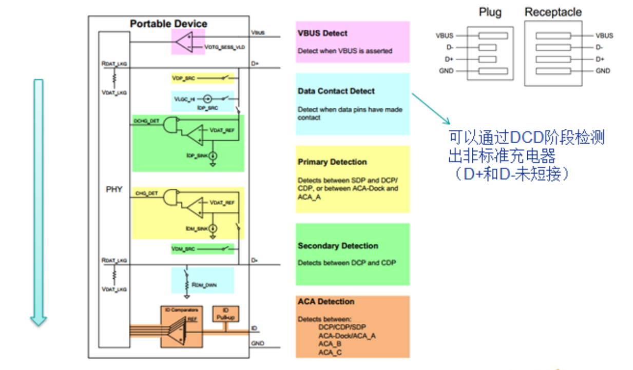
Abbildung 8-1. Ladeerkennung. Typische SDP-Signale D+/D-:
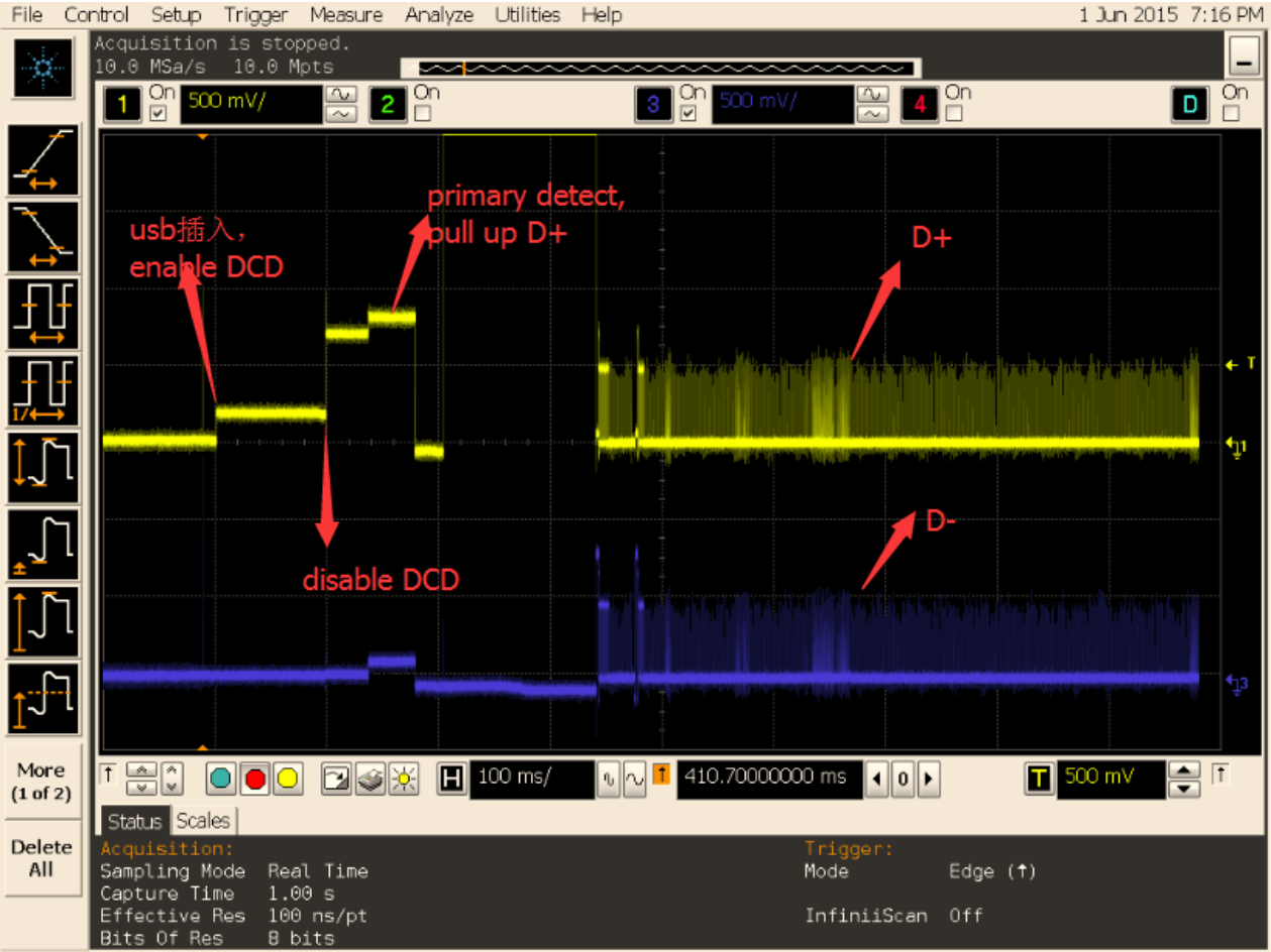
Abbildung 8-2. SDP-Signale. Typische DCP-Signale D+/D-:
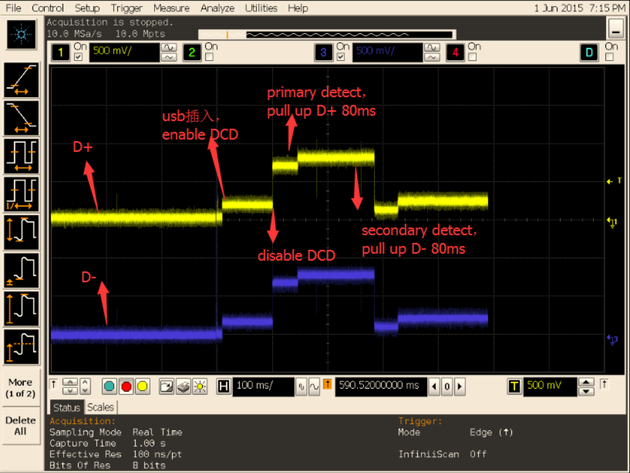
Abbildung 8-3. DCP-Signale. Langsames Laden kann durch als SDP fehlklassifiziertes DCP mit 500mA-Limit entstehen, etwa wegen instabilem Kabel oder fehlerhaftem Treiber. Schritte:
- UART-Log beim Ladeanschluss erfassen; erwartet wird DCP.
- SDP im Log bedeutet Fehlerkennung. Kabel wechseln und erneut testen. Bleibt der Fehler, D+/D- beim Einstecken per Oszilloskop erfassen und mit fehlerhaftem Kernellog an den technischen Support geben.
- Wird DCP korrekt erkannt, aber langsam geladen, können Lade-IC oder Batterie ursächlich sein.
8.2.6 Übertragungsrate
Wesentliche Faktoren sind USB-Signalqualität und Controller-Bustakt,
CPU-/DDR-Takt, Speicherleistung, Dateisystem und Klassentreiber. Siehe Rockchip_Developer_Guide_Linux_USB_Performance_Analysis_CN.
8.2.7 Enumerationsgeschwindigkeit
high-speed im Log bedeutet USB 2.0, super-speed USB 3.0.
8.2.8 USB 3.0 wird nicht erkannt
Bleibt USB-3.0-Einstecken ohne Reaktion, hängt der Ablauf meist im PHY-Link-Training, also an Signalen. Training per USB-3.0-Analysator erfassen und mit der LTSSM der Spezifikation vergleichen.
8.2.9 USB-3.0-Kopierfehler
VBUS-Stromversorgung prüfen; gleiche Operation am PC vergleichen; Protokoll per USB-3.0-Analysator erfassen; Datenblockgröße pro Transfer verringern; xHCI aktualisieren und Debuglog aktivieren.
8.2.10 USB-3.0-Kameraübertragung
Meist betrifft dies USB-Zugriff auf DDR. Quellenmaßnahmen: DDR auf 800MHz fixieren; USB-QOS erhöhen; UVC-Interruptverarbeitung optimieren und memcpy in die untere Hälfte verschieben; URB-Puffer mit kmalloc statt dma_alloc_coherent reservieren; bei Rockchip-UVC-Gadget TxFIFO dynamisch vergrößern.
8.3 USB-Treiber am PC
Rockchip-Entwicklung nutzt häufig rockusb zum Firmwareladen und ADB zur Fehlersuche.
- Windows benötigt den speziellen Rockchip-Treiber; Installation mit DriverAssitant.
- Ubuntu benötigt keinen speziellen Herstellertreiber.
9. USB-Signalqualität prüfen
Siehe Rockchip_Developer_Guide_USB_SQ_Test_CN und Rockchip_Introduction_USB_SQ_Tool_CN. Rockchip USB SQ Tool: https://redmine.rockchip.com.cn/documents/113
Technische Ergänzungen aus Chinesisch V2.4.0 und Quellenunterschiede
RK3288 EHCI/OHCI steht chinesisch als 1, englisch als 0 in der Tabelle. Die xHCI-Gesamtbandbreite ist 8Gbps gegenüber 8.48Gbps. Chinesisch verweist für Device-Endpunkte auf das Chiphandbuch, Englisch nennt 7 IN / 6 OUT / 13 Ressourcen. Diese Unterschiede sind nicht hardwareseitig geklärt. Chinesisch §1.6 beschränkt den beschriebenen Type-C-PHY auf RK3399/RK3399Pro. Englisch §1.3 ergänzt paketbasierte dynamische FIFO-Zuteilung. Beispiele nicht auf sämtliche ArmSoM-Boards übertragen.
VID/PID und Programmiertools
Chinesisch §6.3 begrenzt Rockchip VID 0x2207 ausdrücklich auf Entwicklung/Debugging. Ein USB-IF-zertifiziertes Produkt benötigt eine eigene autorisierte VID über USB-IF-Mitgliedschaft. Maskrom-/Loader-Rockusb-PID und Google-Accessory-VID/PID dürfen nicht geändert werden. Benutzer-PID sollte obere 8 Bit null haben und Tabellenkonflikte vermeiden, damit Rockchip-Programmiertools Geräte nicht falsch erkennen; PC-Treiberladen und USB-Anwendung sind gewöhnlich nicht betroffen. Die ältere englische Tabelle nennt ACCESSORY PID 0x18d1, die chinesische 0x2d00. Beide Quellenwerte bleiben sichtbar. Es folgen die vollständige chinesische und die Programmiertool-Tabelle.
Rockchip-Tools erkennen Gerätefunktionen anhand VID/PID und können beispielsweise Modi wechseln. Unter Windows ermöglicht config.ini zusätzliche eigene VID/PID; dessen Anleitung beachten.
Zusätzliche Debugschnittstellen aus chinesisch §7.1
[usb controller name] durch den tatsächlichen Device-Controller ersetzen. soft_connect trennt/verbindet Gadget; current_speed zeigt die ausgehandelte Geschwindigkeit und state Zustände wie not attached/configured:
echo disconnect > /sys/class/udc/[usb controller name]/soft_connect
echo connect > /sys/class/udc/[usb controller name]/soft_connect
cat /sys/class/udc/[usb controller name]/current_speed
cat /sys/class/udc/[usb controller name]/state
Jeder usb*-Knoten unter /sys/bus/usb/drivers/usb entspricht einem Host. bind/unbind initialisiert ihn neu und enumeriert angeschlossene Geräte erneut. Gadget bietet /sys/bus/platform/drivers/[usb controller name]/bind und unbind; die RV1126-UVC-Wiederherstellung steht im Codeanhang unten. Chinesisch verweist auf USB SQ Tool https://redmine.rockchip.com.cn/documents/109, Englisch am Ende auf /documents/113. Beide Quellenlinks bleiben erhalten.
Zusätzliche Fehleranalyse aus chinesisch §8.2
Teilen mehrere Controller einen Anschluss oder bedient einer mehrere Anschlüsse, können elektronische Schalter Signale und Versorgung umlegen. Controller-Versorgungen müssen unabhängig und Verbindungen korrekt bleiben. Szenario 1: Ein Anschluss nutzt USB 2.0 Host für Host und USB 2.0 OTG für Device. Im Host-Modus Signale zum Host und VBUS aus dessen Versorgung führen, ohne Device-VBUS-Erkennung zu beeinträchtigen; im Device-Modus Signale zu OTG und VBUS vom PC. Szenario 2: Ein OTG-Controller bedient getrennte Host-/Device-Anschlüsse. Als Host DP/DM zum Host-Anschluss mit 5V/500mA; als Device zum Device-Anschluss und nur PC-5V erkennen.
Kein Device-Log: Modus, Schaltung, Signale und danach USB_DET-Low→High beim Einstecken prüfen. Normale Enumeration ohne Zugriff: MTP/PTP wählen, logcat erfassen und Android-vold/mtpserver betreuen lassen. Kopierfehler: Augendiagramm/USB-Verkehr prüfen, Flash-/SD-Timeouts untersuchen (Quelle: Wiederverbindungslogs etwa alle 10s unter Windows XP), bei gleicher Fehlerposition Partition prüfen. Die Quelle nennt chkdsk E: /f für E:. Dies verändert das Dateisystem; nur als Quellenmaterial erhalten, nicht ausgeführt. Dauerhaft hohes VBUS nach Abziehen beeinträchtigt auch Suspend/Wakeup und verlangt Hardwareprüfung.
Ein Host liefert 5V und mindestens 500mA, danach Enumerationslogs. Ohne Log: Schalterverdrahtung, Host-Modus und Versorgung prüfen. Enumeration ohne Klassenlog: Klassentreiber aktivieren. Vollständige Logs und Knoten ohne Android-Funktion: Android-Integration fehlt. vold muss /dev/block/sda unter /udisk für Medienbibliothek/Dateimanager mounten; HID benötigt ebenfalls Android-Unterstützung. /system/etc/vold.fstab prüfen: tatsächlich kann usb20_OTG oder die Endung usb1 erforderlich sein. Die ursprüngliche dev_mount-Zeile bleibt unten erhalten. Android-Entwickler hinzuziehen. transfer_buffer sowie data von usb_control_msg benötigen 4-Byte-Ausrichtung. OTG-Host erkennt nicht: OTG-Konfiguration, ID Low und VBUS 5V prüfen, danach Fehlerlogs sammeln.
Bleibt die Kamera nach Konfigurations- und Boot-Anschlussprüfung defekt, Logs an USB-/Camera-Entwickler geben. Hotplug verlangt Android-Camera-Anpassungen, keine USB-Treiberänderung. Bei Ladefehlerkennung verlangt Chinesisch zusätzlich nach Kabelwechsel die D+/D–Kurzschlussprüfung per Multimeter. Für RK3399 wird DriverAssitant v4.4 genannt. Unprogrammierte Chips/Upgrade-Modus nutzen rockusb, laufende Geräte mit USB debugging ADB.
10. USB-Entwicklungsunterlagen
Chinesisch §10 verweist auf Dokumente, Referenzdesigns und Problemlösungen in Redmine → FAE-Projekt → Documents: https://redmine.rockchip.com.cn/documents/113. Konto kann erforderlich sein. Dieser Abschnitt fehlt im englischen Original.
Editierbare Type-C-Pinbelegung
| Pin | Signal | Pin | Signal |
|---|---|---|---|
| A1 | GND | B1 | GND |
| A2 | TX1+ | B2 | TX2+ |
| A3 | TX1− | B3 | TX2− |
| A4 | VBUS | B4 | VBUS |
| A5 | CC1 | B5 | CC2 |
| A6 | D+ | B6 | D+ |
| A7 | D− | B7 | D− |
| A8 | SBU1 | B8 | SBU2 |
| A9 | VBUS | B9 | VBUS |
| A10 | RX2− | B10 | RX1− |
| A11 | RX2+ | B11 | RX1+ |
| A12 | GND | B12 | GND |
Abweichende Codebeispiele der anderen Quellfassung
Folgende chinesische Blöcke weichen wörtlich von Englisch ab, auch durch Seitenumbrüche oder Kommentare. Es sind alternative Originalbeispiele, kein zusammen auszuführendes Skript; Parameter bleiben zum Vergleich erhalten.
CN · PDF p.25 · #149
Device Drivers  --->
    -*- Support for Host-side USB
CN · PDF p.26 · #150
[*] USB support  --->
    ...
    <*> xHCI HCD (USB 3.0) support
    -*- Generic xHCI driver for a platform device
    ...
    <*> EHCI HCD (USB 2.0) support
    [ ]     Root Hub Transaction Translators
    [*]     Improved Transaction Translator scheduling
    <*> Generic EHCI driver for a platform device
    ...
    <*> OHCI HCD (USB 1.1) support
    < >     OHCI support for PCI-bus USB controllers
    <*>     Generic OHCI driver for a platform device
CN · PDF p.26 · #156
DeviceDrivers  --->
    [*]USB support  --->
        [*] USB Gadget Support  --->
            ...
CN · PDF p.27 · #157
USBGadget Drivers (USB functions configurable through configfs)  --->
    [ ]       Generic serial bulk in/out
    [*]       Abstract Control Model (CDC ACM)
    [ ]       Object Exchange Model (CDC OBEX)
    [ ]       Network Control Model (CDC NCM)
    [ ]       Ethernet Control Model (CDC ECM)
    [ ]       Ethernet Control Model (CDC ECM) subset
    [*]       RNDIS
    [ ]       Ethernet Emulation Model (EEM)
    [*]       Mass storage
    [ ]       Loopback and sourcesink function (for testing)
    [*]       Function filesystem (FunctionFS)
    [*]       MTP gadget
    [*]         PTP gadget
    [*]       Accessory gadget
    [*]         Audio Source gadget
    [*]       Uevent notification of Gadget state
    [ ]       Audio Class 1.0
    [ ]       Audio Class 2.0
    [*]       MIDI function
    [ ]       HID function
    [ ]       USB Webcam function
    [ ]       Printer function
CN · PDF p.27 · #162
Device Drivers --->
    SCSI device support --->
        <*> SCSI device support
        [ ] SCSI: use blk-mq I/O path by default
        [*] legacy /proc/scsi/ support
            *** SCSI support type (disk, tape, CD-ROM) ***
        <*> SCSI disk support
        < > SCSI tape support
        < > SCSI OnStream SC-x0 tape support
        < > SCSI CDROM support
        <*> SCSI generic support
        <*> SCSI media changer support
        [*] Verbose SCSI error reporting (kernel size +=75K)
        [*] SCSI logging facility
CN · PDF p.28 · #163
[*] Asynchronous SCSI scanning
    SCSI Transports  --->
[*] SCSI low-level drivers  --->
[ ] PCMCIA SCSI adapter support  ----
[ ] SCSI Device Handlers  ----
CN · PDF p.28 · #170
Device Driver --->
    [*] Network device support  --->
        <*>   PPP (point-to-point protocol) support
            <*>     PPP BSD-Compress compression
            <*>     PPP Deflate compression
            [*]     PPP filtering
            <*>     PPP MPPE compression (encryption)
            [*]     PPP multilink support
            <*>     PPP over Ethernet
            <*>     PPP over L2TP
            <*>     PPP on L2TP Access Concentrator
            <*>     PPP on PPTP Network Server
            <*>     PPP support for async serial ports
            <*>     PPP support for sync tty ports
CN · PDF p.30 · #183
Device Driver --->
    [*] Network device support  --->
        <*> USB Network Adapters  --->
            <*> USB CATC NetMate-based Ethernet device support
            <*> USB KLSI KL5USB101-based ethernet device support
            <*> USB Pegasus/Pegasus-II based ethernet device support
            <*> USB RTL8150 based ethernet device support
            <*> Realtek RTL8152/RTL8153 Based USB Ethernet Adapters
            < > Microchip LAN78XX Based USB Ethernet Adapters
            <*> Multi-purpose USB Networking Framework
            <*>     ASIX AX88xxx Based USB 2.0 Ethernet Adapters
            <*>     ASIX AX88179/178A USB 3.0/2.0 to Gigabit Ethernet
            -*- CDC Ethernet support (smart devices such as cable modems)
            <*> CDC EEM support
            -*- CDC NCM support
            < > Huawei NCM embedded AT channel support
            <*> CDC MBIM support
            <*> Davicom DM96xx based USB 10/100 ethernet devices
            < > CoreChip-sz SR9700 based USB 1.1 10/100 ethernet devices
            < > CoreChip-sz SR9800 based USB 2.0 10/100 ethernet devices
            <*> SMSC LAN75XX based USB 2.0 gigabit ethernet devices
            <*> SMSC LAN95XX based USB 2.0 10/100 ethernet devices
            <*> GeneSys GL620USB-A based cables
            <*> NetChip 1080 based cables (Laplink, ...)
            <*> Prolific PL-2301/2302/25A1/27A1 based cables
            <*> MosChip MCS7830 based Ethernet adapters
            <*> Host for RNDIS and ActiveSync devices
            <*> Simple USB Network Links (CDC Ethernet subset)
            [*]     ALi M5632 based 'USB 2.0 Data Link' cables
            [*]     AnchorChips 2720 based cables (Xircom PGUNET, ...)
            [*]     eTEK based host-to-host cables (Advance, Belkin, ...)
            [*]     Embedded ARM Linux links (iPaq, ...)
            [*]     Epson 2888 based firmware (DEVELOPMENT)
            [*]     KT Technology KC2190 based cables (InstaNet)
            <*> Sharp Zaurus (stock ROMs) and compatible
            <*> Conexant CX82310 USB ethernet port
            <*> Samsung Kalmia based LTE USB modem
            <*> QMI WWAN driver for Qualcomm MSM based 3G and LTE modems
            <*> Option USB High Speed Mobile Devices
            <*> Intellon PLC based usb adapter
            <*> Apple iPhone USB Ethernet driver
            <*> USB-to-WWAN Driver for Sierra Wireless modems
            < > LG VL600 modem dongle
            < > QingHeng CH9200 USB ethernet support
CN · PDF p.31 · #190
Device Drivers --->
    [*] USB support --->
        -*- Support for Host-side USB
        ...
        [*]     Disable external hubs
CN · PDF p.32 · #199
grf: syscon@ff770000 {
    compatible = "rockchip,rk3399-grf", "syscon", "simple-mfd";
    reg = <0x0 0xff770000 0x0 0x10000>;
    #address-cells = <1>;
    #size-cells = <1>;

    u2phy0: usb2-phy@e450 {
        compatible = "rockchip,rk3399-usb2phy";
CN · PDF p.33 · #200
        reg = <0xe450 0x10>;
        clocks = <&cru SCLK_USB2PHY0_REF>;
        clock-names = "phyclk";
        #clock-cells = <0>;
        clock-output-names = "clk_usbphy0_480m";
        status = "disabled";

        u2phy0_host: host-port {
            #phy-cells = <0>;
            interrupts = <GIC_SPI 27 IRQ_TYPE_LEVEL_HIGH 0>;
            interrupt-names = "linestate";
            status = "disabled";
        };

        u2phy0_otg: otg-port {
            #phy-cells = <0>;
            interrupts = <GIC_SPI 103 IRQ_TYPE_LEVEL_HIGH 0>,
                         <GIC_SPI 104 IRQ_TYPE_LEVEL_HIGH 0>,
                         <GIC_SPI 106 IRQ_TYPE_LEVEL_HIGH 0>;
            interrupt-names = "otg-bvalid", "otg-id",
                              "linestate";
            status = "disabled";
        };
    };
};
CN · PDF p.33 · #202
vcc5v0_host: vcc5v0-host-regulator {
    compatible = "regulator-fixed";
    enable-active-high;
    gpio = <&gpio4 25 GPIO_ACTIVE_HIGH>;
    pinctrl-names = "default";
    pinctrl-0 = <&host_vbus_drv>;
    regulator-name = "vcc5v0_host";
    regulator-always-on;
};

usb2 {
    host_vbus_drv: host-vbus-drv {
        rockchip,pins =
                <4 25 RK_FUNC_GPIO &pcfg_pull_none>;
    };
};
CN · PDF p.34 · #209
tcphy0: phy@ff7c0000 {
    compatible = "rockchip,rk3399-typec-phy";
    reg = <0x0 0xff7c0000 0x0 0x40000>;
    rockchip,grf = <&grf>;
    #phy-cells = <1>;
CN · PDF p.35 · #210
    clocks = <&cru SCLK_UPHY0_TCPDCORE>,
             <&cru SCLK_UPHY0_TCPDPHY_REF>;
    clock-names = "tcpdcore", "tcpdphy-ref";
    assigned-clocks = <&cru SCLK_UPHY0_TCPDCORE>;
    assigned-clock-rates = <50000000>;
    power-domains = <&power RK3399_PD_TCPD0>;
    resets = <&cru SRST_UPHY0>,
             <&cru SRST_UPHY0_PIPE_L00>,
             <&cru SRST_P_UPHY0_TCPHY>;
    reset-names = "uphy", "uphy-pipe", "uphy-tcphy";
    rockchip,typec-conn-dir = <0xe580 0 16>;
    rockchip,usb3tousb2-en = <0xe580 3 19>;
    rockchip,usb3-host-disable = <0x2434 0 16>;
    rockchip,usb3-host-port = <0x2434 12 28>;
    rockchip,external-psm = <0xe588 14 30>;
    rockchip,pipe-status = <0xe5c0 0 0>;
    rockchip,uphy-dp-sel = <0x6268 19 19>;
    status = "disabled";

    tcphy0_dp: dp-port {
        #phy-cells = <0>;
    };

    tcphy0_usb3: usb3-port {
        #phy-cells = <0>;
    };
};
CN · PDF p.37 · #226
usb20_otg: usb@ff580000 {
    compatible = "rockchip,rk3328-usb", "rockchip,rk3066-usb",
                 "snps,dwc2";
    reg = <0x0 0xff580000 0x0 0x40000>;
    interrupts = <GIC_SPI 23 IRQ_TYPE_LEVEL_HIGH>;
    clocks = <&cru HCLK_OTG>, <&cru HCLK_OTG_PMU>;
    clock-names = "otg", "otg_pmu";
    dr_mode = "otg";
    g-np-tx-fifo-size = <16>;
    g-rx-fifo-size = <275>;
    g-tx-fifo-size = <256 128 128 64 64 32>;
    g-use-dma;
    phys = <&u2phy_otg>;
    phy-names = "usb2-phy";
    status = "disabled";
};
CN · PDF p.38 · #233
usbdrd3_0: usb0 {
        compatible = "rockchip,rk3399-dwc3";
        clocks = <&cru SCLK_USB3OTG0_REF>, <&cru SCLK_USB3OTG0_SUSPEND>,
CN · PDF p.39 · #234
         <&cru ACLK_USB3OTG0>, <&cru ACLK_USB3_GRF>;
    clock-names = "ref_clk", "suspend_clk",
              "bus_clk", "grf_clk";
    power-domains = <&power RK3399_PD_USB3>;
    resets = <&cru SRST_A_USB3_OTG0>;
    reset-names = "usb3-otg";
    #address-cells = <2>;
    #size-cells = <2>;
    ranges;
    status = "disabled";

    usbdrd_dwc3_0: dwc3@fe800000 {
        compatible = "snps,dwc3";
        reg = <0x0 0xfe800000 0x0 0x100000>;
        interrupts = <GIC_SPI 105 IRQ_TYPE_LEVEL_HIGH 0>;
        dr_mode = "otg";
        phys = <&u2phy0_otg>, <&tcphy0_usb3>;
        phy-names = "usb2-phy", "usb3-phy";
        phy_type = "utmi_wide";
        snps,dis_enblslpm_quirk;
        snps,dis-u2-freeclk-exists-quirk;
        snps,dis_u2_susphy_quirk;
        snps,dis-del-phy-power-chg-quirk;
        snps,tx-ipgap-linecheck-dis-quirk;
        snps,xhci-slow-suspend-quirk;
        snps,xhci-trb-ent-quirk;
        snps,usb3-warm-reset-on-resume-quirk;
        status = "disabled";
    };
};
CN · PDF p.39 · #239
extcon_usb: extcon-usb {
        compatible = "linux,extcon-usb-gpio";
        /* 硬件设计对电平做了反向处理,这⾥必须配置为 GPIO_ACTIVE_LOW */
        vbus-gpio = <&gpio1 RK_PC5 GPIO_ACTIVE_LOW>;
        pinctrl-names = "default";
CN · PDF p.40 · #240
        pinctrl-0 = <&usb_extcon_vbus>;
        status = "okay";
};

&pinctrl {
        usb {
                usb_extcon_vbus: usb-extcon-vbus {
                rockchip,pins = <1 RK_PC5 RK_FUNC_GPIO &pcfg_pull_none>;
            };
        };
};

&u2phy_otg0 {
        /* 添加属性 rockchip,gpio-vbus-det,表⽰ phy 驱动⽀持 VBUS GPIO 检测⽅式 */
        rockchip,gpio-vbus-det;
        status = "okay";
};

&usb2phy {
        extcon = <&extcon_usb>;
        status = "okay";
};
CN · PDF p.40 · #245
extcon_usb: extcon-usb {
        compatible = "linux,extcon-usb-gpio";
        id-gpio = <&gpio3 RK_PB4 GPIO_ACTIVE_HIGH>;
        /* 注意 pinctrl-names 要设置为 default, 否则 pinctrl 节点的 pcfg_pull_up 配置会不⽣效 */
        pinctrl-names = "default";
        pinctrl-0 = <&usb_extcon_id>;
        status = "okay";
};

&pinctrl {
        usb {
                usb_extcon_id: usb-extcon-id {
CN · PDF p.41 · #246
                        /* ID 默认要内部拉⾼,配置为 pcfg_pull_up */
                        rockchip,pins = <3 RK_PB4 RK_FUNC_GPIO &pcfg_pull_up>;
                };
        };
};

&u2phy_otg0 {
        rockchip,gpio-id-det;
        status = "okay";
};

&usb2phy {
        extcon = <&extcon_usb>;
        status = "okay";
};
CN · PDF p.41 · #249
extcon_usb: extcon-usb {
        compatible = "linux,extcon-usb-gpio";
        vbus-gpio = <&gpio3 RK_PB2 GPIO_ACTIVE_LOW>;
        id-gpio = <&gpio3 RK_PB4 GPIO_ACTIVE_HIGH>;
        /* 注意 pinctrl-names 要设置为 default, 否则 pinctrl 节点的 pcfg_pull_up 配置会不⽣效 */
        pinctrl-names = "default";
        /* 注意 pinctrl-0 同时引⽤ usb_extcon_vbus 和 usb_extcon_id */
        pinctrl-0 = <&usb_extcon_vbus &usb_extcon_id>;
        status = "okay";
};

&pinctrl {
        usb {
                usb_extcon_id: usb-extcon-id {
                        rockchip,pins = <3 RK_PB4 RK_FUNC_GPIO &pcfg_pull_up>;
                };

                usb_extcon_vbus: usb-extcon-vbus {
                        rockchip,pins = <3 RK_PB2 RK_FUNC_GPIO &pcfg_pull_none>;
                };
        };
};

&u2phy_otg0 {
        rockchip,gpio-vbus-det;
        rockchip,gpio-id-det;
        status = "okay";
};

&usb2phy {
CN · PDF p.42 · #250
        extcon = <&extcon_usb>;
        status = "okay";
};
CN · PDF p.45 · #268
static const struct rockchip_usb2phy_cfg rk3399_phy_cfgs[] = {
        {
                .reg            = 0xe450,
                .num_ports      = 2,
                .phy_tuning     = rk3399_usb2phy_tuning,
                .clkout_ctl     = { 0xe450, 4, 4, 1, 0 },
                .port_cfgs      = {
                        [USB2PHY_PORT_OTG] = {
                                .phy_sus = { 0xe454, 8, 0, 0x052, 0x1d1 },
                                .bvalid_det_en  = { 0xe3c0, 3, 3, 0, 1 },
                                .bvalid_det_st  = { 0xe3e0, 3, 3, 0, 1 },
                                .bvalid_det_clr = { 0xe3d0, 3, 3, 0, 1 },
                                .bypass_dm_en   = { 0xe450, 2, 2, 0, 1 },
                                .bypass_sel     = { 0xe450, 3, 3, 0, 1 },
                                .idfall_det_en  = { 0xe3c0, 5, 5, 0, 1 },
                                .idfall_det_st  = { 0xe3e0, 5, 5, 0, 1 },
                                .idfall_det_clr = { 0xe3d0, 5, 5, 0, 1 },
                                .idrise_det_en  = { 0xe3c0, 4, 4, 0, 1 },
                                .idrise_det_st  = { 0xe3e0, 4, 4, 0, 1 },
                                .idrise_det_clr = { 0xe3d0, 4, 4, 0, 1 },
                                .ls_det_en      = { 0xe3c0, 2, 2, 0, 1 },
                                .ls_det_st      = { 0xe3e0, 2, 2, 0, 1 },
                                .ls_det_clr     = { 0xe3d0, 2, 2, 0, 1 },
                                .utmi_avalid    = { 0xe2ac, 7, 7, 0, 1 },
                                .utmi_bvalid    = { 0xe2ac, 12, 12, 0, 1 },
                                .utmi_iddig     = { 0xe2ac, 8, 8, 0, 1 },
                                .utmi_ls        = { 0xe2ac, 14, 13, 0, 1 },
                                .vbus_det_en    = { 0x449c, 15, 15, 1, 0 },
                        },
                        [USB2PHY_PORT_HOST] = {
                                .phy_sus        = { 0xe458, 1, 0, 0x2, 0x1 },
                                .ls_det_en      = { 0xe3c0, 6, 6, 0, 1 },
                                .ls_det_st      = { 0xe3e0, 6, 6, 0, 1 },
                                .ls_det_clr     = { 0xe3d0, 6, 6, 0, 1 },
                                .utmi_ls        = { 0xe2ac, 22, 21, 0, 1 },
                                .utmi_hstdet    = { 0xe2ac, 23, 23, 0, 1 }
                        }
CN · PDF p.46 · #269
        },
        .chg_det = {
                .opmode         = { 0xe454, 3, 0, 5, 1 },
                .cp_det         = { 0xe2ac, 2, 2, 0, 1 },
                .dcp_det        = { 0xe2ac, 1, 1, 0, 1 },
                .dp_det         = { 0xe2ac, 0, 0, 0, 1 },
                .idm_sink_en    = { 0xe450, 8, 8, 0, 1 },
                .idp_sink_en    = { 0xe450, 7, 7, 0, 1 },
                .idp_src_en     = { 0xe450, 9, 9, 0, 1 },
                .rdm_pdwn_en    = { 0xe450, 10, 10, 0, 1 },
                .vdm_src_en     = { 0xe450, 12, 12, 0, 1 },
                .vdp_src_en     = { 0xe450, 11, 11, 0, 1 },
        },
},
{
        .reg            = 0xe460,
        .num_ports      = 2,
        .phy_tuning     = rk3399_usb2phy_tuning,
        .clkout_ctl     = { 0xe460, 4, 4, 1, 0 },
        .port_cfgs      = {
                [USB2PHY_PORT_OTG] = {
                        .phy_sus = { 0xe464, 8, 0, 0x052, 0x1d1 },
                        .bvalid_det_en  = { 0xe3c0, 8, 8, 0, 1 },
                        .bvalid_det_st  = { 0xe3e0, 8, 8, 0, 1 },
                        .bvalid_det_clr = { 0xe3d0, 8, 8, 0, 1 },
                        .idfall_det_en  = { 0xe3c0, 10, 10, 0, 1 },
                        .idfall_det_st  = { 0xe3e0, 10, 10, 0, 1 },
                        .idfall_det_clr = { 0xe3d0, 10, 10, 0, 1 },
                        .idrise_det_en  = { 0xe3c0, 9, 9, 0, 1 },
                        .idrise_det_st  = { 0xe3e0, 9, 9, 0, 1 },
                        .idrise_det_clr = { 0xe3d0, 9, 9, 0, 1 },
                        .ls_det_en      = { 0xe3c0, 7, 7, 0, 1 },
                        .ls_det_st      = { 0xe3e0, 7, 7, 0, 1 },
                        .ls_det_clr     = { 0xe3d0, 7, 7, 0, 1 },
                        .utmi_avalid    = { 0xe2ac, 10, 10, 0, 1 },
                        .utmi_bvalid    = { 0xe2ac, 16, 16, 0, 1 },
                        .utmi_iddig     = { 0xe2ac, 11, 11, 0, 1 },
                        .utmi_ls        = { 0xe2ac, 18, 17, 0, 1 },
                        .vbus_det_en    = { 0x451c, 15, 15, 1, 0 },
                },
                [USB2PHY_PORT_HOST] = {
                        .phy_sus        = { 0xe468, 1, 0, 0x2, 0x1 },
                        .ls_det_en      = { 0xe3c0, 11, 11, 0, 1 },
                        .ls_det_st      = { 0xe3e0, 11, 11, 0, 1 },
                        .ls_det_clr     = { 0xe3d0, 11, 11, 0, 1 },
                        .utmi_ls        = { 0xe2ac, 26, 25, 0, 1 },
                        .utmi_hstdet    = { 0xe2ac, 27, 27, 0, 1 }
                }
        },
        .chg_det = {
                .opmode         = { 0xe464, 3, 0, 5, 1 },
                .cp_det         = { 0xe2ac, 5, 5, 0, 1 },
                .dcp_det        = { 0xe2ac, 4, 4, 0, 1 },
CN · PDF p.47 · #270
                        .dp_det         = { 0xe2ac, 3, 3, 0, 1 },
                        .idm_sink_en    = { 0xe460, 8, 8, 0, 1 },
                        .idp_sink_en    = { 0xe460, 7, 7, 0, 1 },
                        .idp_src_en     = { 0xe460, 9, 9, 0, 1 },
                        .rdm_pdwn_en    = { 0xe460, 10, 10, 0, 1 },
                        .vdm_src_en     = { 0xe460, 12, 12, 0, 1 },
                        .vdp_src_en     = { 0xe460, 11, 11, 0, 1 },
                },
        },
        { /* sentinel */ }
};
CN · PDF p.54 · #301
~/src/android_Q/kernel/drivers/usb/dwc2$ tree
.
├── core.c        (dwc2 core reset, 配置 core param等通⽤操作)
├── core.h
├── core_intr.c   (dwc2 通⽤中断事件,包括otg intr,id intr,wakeup intr等)
├── debugfs.c     (dwc2 调试接⼝,⽐如打印寄存器信息)
├── debug.h
├── gadget.c      (dwc2 gadget mode相关的所有任务,如 gadget 初始化,gadget 中断事件)
├── hcd.c         (dwc2 host mode相关任务以及core init,phy init,device/host mode切换)
├── hcd_ddma.c    (dwc2 descriptor DMA相关的任务)
├── hcd.h
├── hcd_intr.c    (dwc2 host mode的所有中断事件处理)
├── hcd_queue.c   (dwc2 host mode的传输队列处理)
├── hw.h
├── Kconfig
├── Makefile
├── pci.c         (pci 总线接⼝的初始化,Rockchip dwc2使⽤ AHB 总线)
└── platform.c    (实现dwc2 probe,根据不同芯⽚的core_params配置,初始化dwc2 lowlevel hw
resources)
CN · PDF p.54 · #306
rk3288:/sys/devices/platform/ff580000.usb # ls
busconnected  fr_interval gsnpsid   modalias       regoffset     uevent
buspower      gadget      guid      mode           regvalue      usb5
bussuspend    ggpio       gusbcfg   mode_ch_tim_en remote_wakeup wr_reg_test
CN · PDF p.55 · #307
devspeed      gnptxfsiz   hcd_frrem pools          spramdump
disconnect_us gotgctl     hcddump   power          subsystem
driver        gpvndctl    hprt0     rd_reg_test    test_sq
enumspeed     grxfsiz     hptxfsiz  regdump        udc

rk3288:/sys/devices/platform/ff580000.usb/driver # ls
bind       dwc_otg_conn_en force_usb_mode uevent vbus_status
debuglevel ff580000.usb    op_state       unbind versio
CN · PDF p.56 · #317
~/src/android_Q/kernel/drivers/usb/host$ tree
├── ehci-dbg.c      (ehci debugfs调试接⼝,如打印 ehci 寄存器信息)
├── ehci.h
├── ehci-hcd.c      (ehci 控制器的初始化,中断事件处理,urb 队列的管理等)
├── ehci-hub.c      (ehci root hub 的控制和状态查询,bus suspend/resume)
├── ehci-mem.c      (ehci mem 的分配和初始化,qtd/qh资源的分配和初始化)
├── ehci-pci.c      (pci 总线接⼝的初始化,Rockchip ehci使⽤ AHB 总线,不使⽤该驱动)
├── ehci-platform.c (ehci 通⽤平台驱动,实现ehci probe,向usb bus注册ehci hcd,使能ehci控制器)
├── ehci-q.c        (ehci qtd/qh传输队列的处理)
├── ehci-sched.c    (ehci interrupt, iso, split iso的周期传输调度处理)
├── ehci-sysfs.c    (ehci sysfs调试接⼝,显⽰ companion 控制器,显⽰ uframe_periodic_max)
├── ehci-timer.c    (ehci timer相关的任务处理)
CN · PDF p.56 · #319
static const struct hc_driver ehci_hc_driver = {
    .description =      hcd_name,
    .product_desc =     "EHCI Host Controller",
    .hcd_priv_size =    sizeof(struct ehci_hcd),
    /*
     * generic hardware linkage
     */
    .irq =          ehci_irq,
    .flags =        HCD_MEMORY | HCD_USB2 | HCD_BH,
    /*
     * basic lifecycle operations
     */
    .reset =        ehci_setup,
    .start =        ehci_run,
    .stop =         ehci_stop,
    .shutdown =     ehci_shutdown,
    /*
     * managing i/o requests and associated device resources
     */
    .urb_enqueue =      ehci_urb_enqueue,
CN · PDF p.57 · #320
    .urb_dequeue =      ehci_urb_dequeue,
    .endpoint_disable = ehci_endpoint_disable,
    .endpoint_reset =   ehci_endpoint_reset,
    .clear_tt_buffer_complete = ehci_clear_tt_buffer_complete,
    /*
     * scheduling support
     */
    .get_frame_number = ehci_get_frame,
    /*
     * root hub support
     */
    .hub_status_data =  ehci_hub_status_data,
    .hub_control =      ehci_hub_control,
    .bus_suspend =      ehci_bus_suspend,
    .bus_resume =       ehci_bus_resume,
    .relinquish_port =  ehci_relinquish_port,
    .port_handed_over = ehci_port_handed_over,
    /*
     * device support
     */
    .free_dev =     ehci_remove_device,
};
CN · PDF p.57 · #322
~/src/android_Q/kernel/drivers/usb/host$ tree
├── ohci-dbg.c     (ohci debugfs调试接⼝,如打印 ohci 寄存器信息)
├── ohci.h
├── ohci-hcd.c     (ohci 控制器的初始化,中断事件处理,urb 队列的管理等)
├── ohci-hub.c     (ohci root hub 的控制和状态查询,bus suspend/resume)
├── ohci-mem.c     (ohci mem 的分配和初始化,td/ed资源的分配和初始化)
├── ohci-pci.c     (pci 总线接⼝的初始化,Rockchip ohci使⽤ AHB 总线,不使⽤该驱动⽂件)
├── ohci-platform.c(ohci 通⽤平台驱动,实现ohci probe,向usb bus注册ohci hcd,使能ohci控制器)
├── ohci-q.c       (ohci td/ed传输队列的处理)
CN · PDF p.57 · #324
static const struct hc_driver ohci_hc_driver = {
    .description =          hcd_name,
    .product_desc =         "OHCI Host Controller",
    .hcd_priv_size =        sizeof(struct ohci_hcd),
    /*
     * generic hardware linkage
    */
    .irq =                  ohci_irq,
    .flags =                HCD_MEMORY | HCD_USB11,
CN · PDF p.58 · #325
    /*
    * basic lifecycle operations
    */
    .reset =                ohci_setup,
    .start =                ohci_start,
    .stop =                 ohci_stop,
    .shutdown =             ohci_shutdown,
    /*
     * managing i/o requests and associated device resources
    */
    .urb_enqueue =          ohci_urb_enqueue,
    .urb_dequeue =          ohci_urb_dequeue,
    .endpoint_disable =     ohci_endpoint_disable,
    /*
    * scheduling support
    */
    .get_frame_number =     ohci_get_frame,
    /*
    * root hub support
    */
    .hub_status_data =      ohci_hub_status_data,
    .hub_control =          ohci_hub_control,
#ifdef CONFIG_PM
    .bus_suspend =          ohci_bus_suspend,
    .bus_resume =           ohci_bus_resume,
#endif
    .start_port_reset = ohci_start_port_reset,
};
CN · PDF p.58 · #328
rk3399:/sys/kernel/debug/fe380000.usb # ls
async bandwidth periodic registers

rk3399:/sys/devices/platform/fe380000.usb # ls
companion driver_override of_node power     uevent              usb5
driver    modalias        pools   subsystem uframe_periodic_max usbmon
CN · PDF p.59 · #331
rk3399:/sys/kernel/debug/usb/ohci/fe3a0000.usb # ls
async periodic registers
CN · PDF p.60 · #342
~/src/kernel-4.19/drivers/usb/dwc3$ tree
.
├── core.c              (dwc3 core probe的实现,分配各种资源,初始化控制器,PM runtime 管理)
├── core.h
├── debugfs.c           (dwc3 debugfs调试接⼝的实现)
├── debug.h
├── drd.c               (dwc3 dule role mode/otg mode 动态切换的处理)
├── dwc3-of-simple.c    (dwc3 通⽤平台驱动,实现dwc3的第⼀级dwc3_of_simple_probe,并通过
of_platform_populate 调⽤dwc3 core的第⼆级dwc3_probe)
├── dwc3-pci.c          (pci 总线接⼝的初始化,Rockchip dwc3使⽤AXI总线,不使⽤该驱动⽂件)
├── dwc3-rockchip-inno.c(RK3328/RK3228H专⽤的glue layer,增加了disconnect work的实现)
├── ep0.c               (dwc3 gadget ep0的任务处理)
├── gadget.c            (dwc3 gadget 除ep0外的端点任务处理,中断的⼊⼝函数实现)
├── gadget.h
├── host.c              (dwc3 host资源分配,并通过platform_device_add调⽤xHCI的xhci_plat_probe)
├── io.h
├── Kconfig
CN · PDF p.61 · #343
├── Makefile
├── trace.c              (dwc3 trace的实现,基于linux的trace接⼝)
├── trace.h
└── ulpi.c               (ulpi phy接⼝的代码实现,Rockchip dwc3不使⽤ulpi)

~/src/kernel-4.19/drivers/usb/host$ tree
├── xhci.c               (初始化xhci_hc_driver,启动xHCI控制器,管理urb队列等)
├── xhci-dbg.c           (实现打印log的调试函数)
├── xhci-dbgcap.c        (xHCI 硬件模块 debug capability的功能实现,Rockchip 不⽀持)
├── xhci-dbgcap.h
├── xhci-debugfs.c       (xHCI debugfs调试接⼝)
├── xhci-debugfs.h
├── xhci-ext-caps.c      (xHCI extended capability的功能实现,Rockchip 不⽀持)
├── xhci-ext-caps.h
├── xhci.h
├── xhci-hub.c           (xHCI root hub 的控制和状态查询,bus suspend/resume)
├── xhci-mem.c           (xHCI mem 管理,包括分配,初始化,释放等操作)
├── xhci-pci.c           (pci 总线接⼝的初始化,Rockchip xHCI使⽤AXI总线,不使⽤该驱动⽂件)
├── xhci-plat.c          (xHCI 通⽤平台驱动,实现xhci_plat_probe,Rockchip 使⽤该驱动)
├── xhci-plat.h
├── xhci-ring.c          (xHCI transfer/command/event ring 的管理)
├── xhci-trace.c         (xHCI trace的实现,基于linux的trace接⼝)
└── xhci-trace.h
CN · PDF p.61 · #347
static const struct hc_driver xhci_hc_driver = {
    .description =      "xhci-hcd",
    .product_desc =     "xHCI Host Controller",
    .hcd_priv_size =    sizeof(struct xhci_hcd *),
    /*
     * generic hardware linkage
     */
    .irq =          xhci_irq,
    .flags =        HCD_MEMORY | HCD_USB3 | HCD_SHARED,
    /*
     * basic lifecycle operations
CN · PDF p.62 · #348
     */
    .reset =        NULL, /* set in xhci_init_driver() */
    .start =        xhci_run,
    .stop =         xhci_stop,
    .shutdown =     xhci_shutdown,
    /*
     * managing i/o requests and associated device resources
     */
    .urb_enqueue =      xhci_urb_enqueue,
    .urb_dequeue =      xhci_urb_dequeue,
    .alloc_dev =        xhci_alloc_dev,
    .free_dev =     xhci_free_dev,
    .alloc_streams =    xhci_alloc_streams,
    .free_streams =     xhci_free_streams,
    .add_endpoint =     xhci_add_endpoint,
    .drop_endpoint =    xhci_drop_endpoint,
    .endpoint_reset =   xhci_endpoint_reset,
    .check_bandwidth =  xhci_check_bandwidth,
    .reset_bandwidth =  xhci_reset_bandwidth,
    .address_device =   xhci_address_device,
    .enable_device =    xhci_enable_device,
    .update_hub_device =    xhci_update_hub_device,
    .reset_device =     xhci_discover_or_reset_device,
    /*
     * scheduling support
     */
    .get_frame_number = xhci_get_frame,
    /*
     * root hub support
     */
    .hub_control =      xhci_hub_control,
    .hub_status_data =  xhci_hub_status_data,
    .bus_suspend =      xhci_bus_suspend,
    .bus_resume =       xhci_bus_resume,
    /*
     * call back when device connected and addressed
     */
    .update_device =        xhci_update_device,
    .set_usb2_hw_lpm =  xhci_set_usb2_hardware_lpm,
    .enable_usb3_lpm_timeout =  xhci_enable_usb3_lpm_timeout,
    .disable_usb3_lpm_timeout = xhci_disable_usb3_lpm_timeout,
    .find_raw_port_number = xhci_find_raw_port_number,
};
CN · PDF p.63 · #351
console:/sys/kernel/debug/fe800000.dwc3 # ls
ep0in  ep1in  ep2in  ep3in  ep4in  ep5in  ep6out     lsp_dump regdump
ep0out ep1out ep2out ep3out ep4out ep5out link_state mode     testmode

console:/sys/kernel/debug/usb/xhci/xhci-hcd.0.auto # ls
command-ring ports          reg-ext-legsup:00   reg-op
devices      reg-cap        reg-ext-protocol:00 reg-runtime
event-ring   reg-ext-dbc:00 reg-ext-protocol:01
CN · PDF p.63 · #353
#RK3399 Type-C0 USB OTG 切换命令
#1.Force host mode
  echo host > sys/kernel/debug/usb@fe800000/rk_usb_force_mode
#2.Force peripheral mode
  echo peripheral > sys/kernel/debug/usb@fe800000/rk_usb_force_mode
CN · PDF p.64 · #355
#RK3399 Type-C0 USB OTG 切换命令
#1.Force host mode
  echo host > sys/devices/platform/usb0/dwc3_mode
#2.Force peripheral mode
  echo peripheral > sys/devices/platform/usb0/dwc3_mode

#RK1808 USB OTG 切换命令
#1.Force host mode
  echo host > sys/devices/platform/usb/dwc3_mode
#2.Force peripheral mode
  echo peripheral > sys/devices/platform/usb/dwc3_mode
CN · PDF p.64 · #357
#RK3399 Type-C0 USB OTG 切换命令
#1.Force host mode
  echo host > sys/devices/platform/ff770000.syscon/ff770000.syscon:usb2-phy@e450/otg_mode
#2.Force peripheral mode
  echo peripheral > sys/devices/platform/ff770000.syscon/ff770000.syscon:usb2-
phy@e450/otg_mode

#其他芯⽚,⽅法类似,只要在 sys/devices/platform 路径下,搜索 otg_mode 节点,然后设置该节点即可。
CN · PDF p.64 · #359
#RK3588 Type-C0 USB OTG 切换命令
#⽅式1. [Legacy] 通过 USB PHY 节点切换
#1.Force host mode
  echo host > /sys/devices/platform/fd5d0000.syscon/fd5d0000.syscon:usb2-phy@0/otg_mode
#2.Force peripheral mode
  echo peripheral > /sys/devices/platform/fd5d0000.syscon/fd5d0000.syscon:usb2-
phy@0/otg_mode

#⽅式2.[New] 通过 USB 控制器节点切换
#1.Force host mode
  echo host > /sys/kernel/debug/usb/fc000000.usb/mode
#2.Force peripheral mode
  echo device > /sys/kernel/debug/usb/fc000000.usb/mode

#其他芯⽚,⽅法类似,只要在 sys/ 路径下,搜索 otg_mode 或者 mode 节点,然后设置该节点即可。
CN · PDF p.72 · #413
&usbdrd_dwc3_1 {
        status = "okay";
        dr_mode = "otg";  /* 配置Type-C1 USB控制器为OTG mode */
        extcon = <&fusb1>; /* 注意:extcon 属性要根据实际的硬件电路设计来配置 */
};
CN · PDF p.74 · #427
echo none > config/usb_gadget/g1/UDC
echo fe900000.dwc3 > config/usb_gadget/g1/UDC
CN · PDF p.77 · #435
echo usb2 > /sys/bus/usb/drivers/usb/unbind
echo usb2 > /sys/bus/usb/drivers/usb/bind
CN · PDF p.78 · #437
1. kill uvc_app #杀掉 uvc 应⽤
2. rm -rf /sys/kernel/config/usb_gadget/rockchip/configs/b.1/f* #移除已绑定的usb func
3. echo ffd00000.dwc3  > /sys/bus/platform/drivers/dwc3/unbind #remove usb 控制器
4. echo ffd00000.dwc3  > /sys/bus/platform/drivers/dwc3/bind #probe usb 控制器
5. cd /sys/kernel/config/usb_gadget/rockchip/configs/b.1 #绑定 usb function
   ln -s ../../functions/rndis.gs0 f1
   ln -s ../../functions/uvc.gs6/ f2
6. echo ffd00000.dwc3 > /sys/kernel/config/usb_gadget/rockchip/UDC #使能 usb 控制器连接
7. restart uvc_app #启动 uvc 应⽤
CN · PDF p.79 · #445
arch/arm64/boot/dts/rockchip/rk3588-android.dtsi
chosen: chosen {
    bootargs = "earlycon=uart8250,mmio32,0xfeb50000 console=ttyFIQ0
irqchip.gicv3_pseudo_nmi=0 rcupdate.rcu_expedited=1 rcu_nocbs=all
usbcore.autosuspend=-1";
};
CN · PDF p.79 · #449
diff --git a/drivers/usb/core/hub.c b/drivers/usb/core/hub.c
CN · PDF p.80 · #450
index fc7d6cdacf16..df8e69e60aaf 100644
--- a/drivers/usb/core/hub.c
+++ b/drivers/usb/core/hub.c
@@ -41,6 +41,8 @@
 #define USB_VENDOR_GENESYS_LOGIC               0x05e3
 #define USB_VENDOR_SMSC                                0x0424
 #define USB_PRODUCT_USB5534B                   0x5534
+#define USB_VENDOR_CYPRESS                     0x04b4
+#define USB_PRODUCT_CY7C65632                  0x6570
 #define HUB_QUIRK_CHECK_PORT_AUTOSUSPEND       0x01
 #define HUB_QUIRK_DISABLE_AUTOSUSPEND          0x02

@@ -5697,6 +5699,11 @@ static const struct usb_device_id hub_id_table[] = {
       .idProduct = USB_PRODUCT_USB5534B,
       .bInterfaceClass = USB_CLASS_HUB,
       .driver_info = HUB_QUIRK_DISABLE_AUTOSUSPEND},
+    { .match_flags = USB_DEVICE_ID_MATCH_VENDOR
+                   | USB_DEVICE_ID_MATCH_PRODUCT,
+      .idVendor = USB_VENDOR_CYPRESS,
+      .idProduct = USB_PRODUCT_CY7C65632,
+      .driver_info = HUB_QUIRK_DISABLE_AUTOSUSPEND},
CN · PDF p.82 · #477
include/linux/usb/quirks.h
drivers/usb/core/quirks.c

/* Lists of quirky USB devices */
static const struct usb_device_id usb_quirk_list[] = {
        { USB_DEVICE(0x0204, 0x6025), .driver_info = USB_QUIRK_RESET_RESUME },
        { USB_DEVICE(0x21c4, 0x0cd1), .driver_info = USB_QUIRK_NO_LPM },
};

static const struct usb_device_id usb_interface_quirk_list[] = {
        { USB_VENDOR_AND_INTERFACE_INFO(0x046d, USB_CLASS_VIDEO, 1, 0),
          .driver_info = USB_QUIRK_RESET_RESUME },
};
CN · PDF p.83 · #478
static const struct usb_device_id usb_endpoint_ignore[] = {
        { USB_DEVICE_INTERFACE_NUMBER(0x06f8, 0xb000, 5), .driver_info = 0x01 },
};
CN · PDF p.83 · #480
include/linux/usb_usual.h
drivers/usb/storage/unusual_devs.h   /* Driver for USB Mass Storage compliant devices */
drivers/usb/storage/unusual_uas.h    /* Driver for USB Attached SCSI devices - Unusual
Devices File */

/* Example of USB Mass Storage unusual device */
UNUSUAL_DEV(0x0951, 0x1697, 0x0100, 0x0100,
                    "Kingston",
                    "DT Ultimate G3",
                    USB_SC_DEVICE, USB_PR_DEVICE, NULL,
                    US_FL_NO_WP_DETECT)

/* Example of USB Attached SCSI unusual device */
UNUSUAL_DEV(0x0b05, 0x1932, 0x0000, 0x9999,
                    "ASUS",
                    "External HDD",
                    USB_SC_DEVICE, USB_PR_DEVICE, NULL,
                    US_FL_IGNORE_UAS)
CN · PDF p.90 · #540
dev_mount udisk /mnt/udisk 1 /devices/platform/usb20_Host/usb2
Originale Vektor-Flussdiagramme
Jedes Diagramm bleibt in zwei Original-PDF-Seitenfragmenten erhalten, nicht als Ersatz für editierbaren Text. VBUS: Device-Hotplug → VBUS-Pegeländerung → GPIO-Interrupt → invertierten GPIO prüfen. Low sendet EXTCON_USB True; PHY setzt bvalid High; steigende Flanke plant otg_sm_work; Ladegeräterkennung; PHY fortsetzen; DP hochziehen und enumerieren. High sendet EXTCON_USB False; PHY setzt bvalid Low; Controller-Disconnect-Interrupt; Gadget-disconnect-Callback; PHY suspendieren; Ende. ID: OTG-Kabel-Hotplug → ID-GPIO-Interrupt. Low sendet EXTCON_USB_HOST True; PHY setzt IDDIG Low; fallende ID-Flanke löst Interrupt aus; Host initialisieren; VBUS regulator aktivieren. High sendet EXTCON_USB_HOST False; PHY setzt IDDIG High; steigende ID-Flanke löst Interrupt aus; Device initialisieren; VBUS regulator deaktivieren; Ende.
Vollständige VID/PID-Tabellen aus Chinesisch V2.4.0
Ergänzung zur älteren englischen Tabelle §6.3. Doppelte PIDs bleiben quellgetreu erhalten, ohne vermutete Auflösung. Quelle: chinesisches PDF, S.73–74.
| USB-Funktion | VID | PID | Hinweise |
|---|---|---|---|
| UMS | 0x2207 | 0x0000 | Linux SDK Mass Storage |
| MTP | 0x2207 | 0x0001 | Android Q + Kernel 4.4 und ältere SDKs sowie Linux SDK |
| PTP | 0x2207 | 0x0002 | Android Q + Kernel 4.4 und ältere SDKs |
| RNDIS | 0x2207 | 0x0003 | Android/Linux SDK |
| MIDI | 0x2207 | 0x0004 | Android SDK |
| UVC | 0x2207 | 0x0005 | Android SDK |
| ADB | 0x2207 | 0x0006 | Android/Linux SDK |
| MTP | 0x2207 | 0x0007 | Android Q + kernel 4.19 und neuere SDKs |
| PTP | 0x2207 | 0x0008 | Android Q + kernel 4.19 und neuere SDKs |
| NTB | 0x2207 | 0x0009 | Für nächste Compute-Stick-Generation reserviert |
| UMS,ADB | 0x2207 | 0x0010 | Kernel 3.10 und ältere SDKs |
| UMS | 0x2207 | 0x0010 | U-Boot UMS |
| MTP,ADB | 0x2207 | 0x0011 | Android Q + kernel 4.4 und ältere SDKs sowie Linux SDK |
| PTP,ADB | 0x2207 | 0x0012 | Android Q + kernel 4.4 und ältere SDKs |
| RNDIS,ADB | 0x2207 | 0x0013 | Android SDK |
| MIDI,ADB | 0x2207 | 0x0014 | Android SDK |
| UVC,ADB | 0x2207 | 0x0015 | Android-SDK-UVC-Verbundgerät |
| UVC,ADB [UAC, RNDIS] |
0x2207 | 0x0016 | Linux-SDK-UVC-Verbundgerät |
| MTP,ADB | 0x2207 | 0x0017 | Android Q + kernel 4.19 und neuere SDKs |
| PTP,ADB | 0x2207 | 0x0018 | Android Q + kernel 4.19 und neuere SDKs |
| UMS,ADB | 0x2207 | 0x0018 | Linux SDK |
| NTB | 0x2207 | 0x0018 | Compute-Stick NPU Transfer Bridge |
| NTB [RNDIS,HID] | 0x2207 | 0x0019 | Für USB-Verbundgerät der nächsten Compute-Stick-Generation reserviert |
| DFU | 0x2207 | 0x0107 | U-Boot USB Device Firmware update |
| Rockusb | 0x2207 | 0x1xxx/0x2xxx/0x3xxx | MASKROM/LOADER-Gerät zum Firmwareladen |
| ACCESSORY | 0x18d1 | 0x2d00 | Von Google definiert |
| ACCESSORY,ADB | 0x18d1 | 0x2d01 | Von Google definiert |
| USB-Funktion | VID | PID |
|---|---|---|
| MSC | 0x2207 | 0x0000/0x0010 |
| MTP | 0x2207 | 0x0001 |
| ADB | 0x2207 | 0x0006/0x0011 |
| UVC | 0x2207 | 0x0016 |
| MASKROM | 0x2207 | 0x1xxx/0x2xxx/0x3xxx |
| LOADER | 0x2207 | 0x1xxx/0x2xxx/0x3xxx |