
Rockchip platform reference for the RK RT-Thread SDK, covering RK2108/RK2118 (SPI2APB mainly RK2118). Matching ArmSoM board support is unconfirmed; no hardware validation was performed. Check SoC, SDK/BSP, RT-Thread version, controller type, IOMUX, wiring and voltage domains before adaptation. Commands and test results are source examples, not ArmSoM measurements; no hardware or flash operations were executed. Only a Chinese original is available; all four languages use Chinese source figures.
RK-KF-YF-093 · V2.2.0
1. Rockchip SPI features
1.1 SPI controller features
SPI (Serial Peripheral Interface).
- Master supports SPI modes 0/1/2/3; slave supports modes 0/1/2/3. Mode 0 is recommended for slave operation to reach the highest rate.
- Usually two chip selects; 8-bit and 16-bit transfers.
- Interrupt and DMA transfer modes; FIFO depth 32 or 64.
- Configurable master read-sampling clock RSD.
- Slave mode; some chips support external-clock sampling in slave mode.
- Configurable LSB/MSB and endianness.
- Some chips provide cs inactive detection, generating an interrupt when CS is released.
- Four-wire MOSI/MOSI transmission (source wording): master MOSI output/MISO input; slave MISO output/MOSI input.
1.2 SPI interface characteristics
| SoC | Master max | Slave max | TX/RX FIFO | Rx Sample Delay unit |
|---|---|---|---|---|
| RK2108 | 50MHz | 16MHz | 64 | \ |
| RK2118 | 50MHz | 50MHz (SPI mode 0) | 64 | 5ns |
The maximum interface rate is theoretical; device routing and PCB quality affect it, so actual measurement governs. On some platforms the PLL strategy cannot divide exactly to the limit; use the highest attainable divided rate. For Rx Sample Delay see “Read-sampling delay configuration”.
1.3 Notes on SPI slave operation
1.3.1 SPI2APB
This document concerns RK SPI, a different IP from RK SPI2APB. RK SPI supports master/slave modes, without a required slave data format. RK SPI2APB supports only slave mode and requires a fixed transfer format.
For SPI2APB, e.g. RK2118 SPI0 (SPI2APB), consult the TRM SPI2APB chapter and Rockchip_Developer_Guide_RT-Thread_SPI2APB.
1.3.2 Transfer sequence
Basic RK SPI slave transfer sequence:
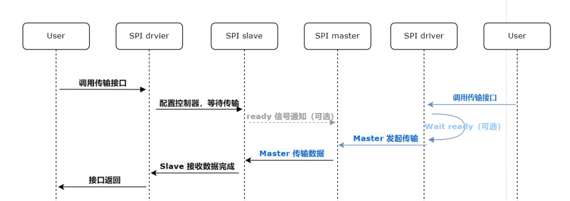
Chinese source figure (p.5)
Slave side:
- The user layer calls the transfer interface. Simplex read-only/write-only and full-duplex transfers are supported; a transfer length must be specified.
- Wait for transfer, with matching master behavior. After register configuration, the controller waits for the remote master. The transfer interface must be called again for every slave transfer. Consider the maximum interval Tgap(max) under RT-Thread; the master must wait at least this interval. Actual application load varies, so no theoretical recommended value is provided: measure it. An optional ready signal provides real-time notification; see “Adding an SPI slave ready signal”.
- Receive data. For lengths greater than half the TX/RX FIFO, software automatically uses DMA to avoid transfer jitter. For lengths no greater than half the FIFO, it uses IRQ transfer.
- Return from the interface. Fixed-length transfer (default) ignores CS release and returns only after the requested amount has been received, otherwise blocking. Flexible-length transfer detects CS release and returns when CS is released early or the configured amount is received, otherwise blocking. See its configuration below.
Master side:
- The user layer calls the transfer interface.
- Optionally wait for ready. Match the slave Tgap(max), preventing two transfers within Tgap. If the slave supports a ready signal, configure a rising-edge interrupt, mark ready valid, and invalidate it after transfer.
- The controller initiates transfer.
1.3.3 Transfer timing

Chinese source figure (p.6)
Step 1: user-layer interface call. Step 2: ready signal (optional). Step 3: wait for transfer. Step 4: data transfer. Step 5: interface returns.
1.3.4 Flexible-length transfers
The RK SDK defaults to fixed-length SPI slave transfers: after the interface sets a length, it returns only after receiving that amount, otherwise waiting indefinitely. Flexible-length mode returns the amount actually transferred after the full configured length arrives or CS is released before completion. This relies on enabling the slave cs inactive hardware feature, which detects CS release. Support is listed below.
| SoC | cs inactive | Flexible Length |
|---|---|---|
| RK2108 | Supported | Not adapted |
| RK2118 | Supported | BURST_SIZE=1: 25MHz; BURST_SIZE=2: 50MHz (max) |
See “Controller configuration”. Besides enabling the feature, choose burst size:
- Smaller burst size reduces SPI/bus efficiency and may lose slave packets, but imposes fewer master-length constraints. RK2118 with burst size 1 supports master sclk only up to 25MHz; above 25MHz packets may be lost, but the master length is unrestricted.
- Larger burst size improves efficiency and supported IO rate, with stricter master-length constraints. RK2118 burst size 2 supports master sclk 50MHz and requires 2-byte alignment.
2. Software
2.1 Source paths
Framework code:
components/drivers/include/drivers/spi.h
components/drivers/spi/spi_core.c
components/drivers/spi/spi_dev.c
components/drivers/spi/qspi_core.c
Driver adaptation layer:
bsp/rockchip-common/drivers/drv_spi.c
bsp/rockchip-common/drivers/drv_spi.h
Test commands; applications can follow this driver:
bsp/rockchip-common/tests/spi_test.c
2.2 Configuration
2.2.1 Controller configuration
Enable the configuration; /dev/spi0..2 devices are created.
RT-Thread bsp drivers  --->
    RT-Thread rockchip "project" drivers  --->
        [*] Enable SPI
        [ ]   Enable SPI0 (SPI2APB)
        [*]   Enable SPI1
        [*]   Enable SPI2
        [*] Support stop SPI slave transmission when cs inactive
              Enable SPI Slave flexible length  --->
RT_USING_SPI_SLAVE_FLEXIBLE_LENGTH enables flexible-length transfer; see that section. RT_USING_SLAVE_DMA_RX_BURST_SIZE sets its DMA burst size, explained in the same section. Flexible-length transfers use DMA by default, so upper-layer buffers and lengths must align to cache line size. SPI0 (SPI2APB) denotes an SPI2APB controller, not RK SPI; see Rockchip_Developer_Guide_RT-Thread_SPI2APB.
2.2.2 Board configuration
Ensure the board-level SPI iomux configuration has been added.
2.3 SPI usage configuration
Parameters: as MASTER the SPI controller supports 0–50MHz (some platforms allow higher frequencies); as SLAVE the source specifies 0–50MHz and says to configure the highest rate for compatibility with masters of different rates. rt_spi_configure() sets frequency, mode and transfer width. Standard RT-Thread parameters:
#define RT_SPI_CPHA     (1<<0)                             /* bit[0]:CPHA, clock phase */
#define RT_SPI_CPOL     (1<<1)                             /* bit[1]:CPOL, clock polarity */

#define RT_SPI_LSB      (0<<2)                             /* bit[2]: 0-LSB */
#define RT_SPI_MSB      (1<<2)                             /* bit[2]: 1-MSB */

#define RT_SPI_MASTER   (0<<3)                             /* SPI master device */
#define RT_SPI_SLAVE    (1<<3)                             /* SPI slave device */

#define RT_SPI_MODE_0       (0 | 0)                        /* CPOL = 0, CPHA = 0 */
#define RT_SPI_MODE_1       (0 | RT_SPI_CPHA)              /* CPOL = 0, CPHA = 1 */
#define RT_SPI_MODE_2       (RT_SPI_CPOL | 0)              /* CPOL = 1, CPHA = 0 */
#define RT_SPI_MODE_3       (RT_SPI_CPOL | RT_SPI_CPHA)    /* CPOL = 1, CPHA = 1 */
Parameters supported by the RK extension of RT-Thread:
#define RK_SPI_RESERVED_RSD_0     (0)
#define RK_SPI_RESERVED_RSD_1     (1)
#define RK_SPI_RESERVED_RSD_2     (2)
#define RK_SPI_RESERVED_RSD_3     (3)
#define RK_SPI_RESERVED_RSD_MASK  (3)
For RSD see “Read-sampling delay configuration”. Include drv_spi.h. Configuration example:
#include <drivers/spi.h>
#include "drv_spi.h"
struct rt_spi_configuration cfg;
struct rt_spi_device *spi_device = RT_NULL;

spi_device = (struct rt_spi_device *)rt_device_find("spi2_0");
if (spi_device ==  RT_NULL)
{
    rt_kprintf("Did not find device\n");
    return;
}

cfg.data_width = 8; /* 配置8bits传输模式 */
cfg.mode = RT_SPI_MASTER | RT_SPI_MSB | RT_SPI_MODE_0;
cfg.max_hz = 20 * 1000 * 1000; /* 配置频率 20Mhz */
spi_device->config.reserved = RT_SPI_RESERVED_RSD_1; /* 配置 rx sample delay 1 级 */
rt_spi_configure(spi_device, &cfg); /* 配置 SPI*/
3. SPI testing
3.1 Configuration
RT-Thread bsp test case  --->
    [*] RT-Thread Common Test case  --->
        [*] Enable BSP Common TEST
        [*]  Enable BSP Common SPI TEST
3.2 Test commands
msh >spi_test
1. spi_test config <spi_device> <is_slave> <spi_mode> <is_msb> <speed>
<data_width>
2. spi_test read   <spi_device> <loops> <size>
3. spi_test write  <spi_device> <loops> <size>
4. spi_test duplex <spi_device> <loops> <size>
5. spi_test cs     <spi_device> <cs_state:1-take, 0-release>
6. spi_test bus    <spi_device> <bus_state:1-take, 0-release>
7. spi_test rate   <spi_device>
8. spi_test loop_thread   <spi_device> <loops> <size> <gap_ms> <random_pattern>
like:
        spi_test config spi1_0 0 3 0 24000000
        spi_test read   spi1_0 1 256
        spi_test write  spi1_0 1 256
        spi_test duplex spi1_0 1 256
        spi_test cs     spi1_0 1
        spi_test bus    spi1_0 1
        spi_test rate   spi1_0
        spi_test loop_thread   spi1_0 1 256 10 1
random_pattern: 0 = incrementing sequence, 1 = random sequence. loops: number of repetitions of the same operation.
3.3 Test examples
3.3.1 Loopback
Short MOSI to MISO and use full-duplex transfer: spi1_0, master_mode, spi_mode_3, lsb, 24MHz.
spi_test config spi1_0 0 3 0 24000000 8
spi_test duplex spi1_0 1 256
A failed loopback prints test fail: MISO did not receive valid MOSI data, so comparison failed. No error output means success. This test is recommended to verify correct master-mode controller operation.
3.3.2 Rate measurement
Configure spi1_0, master_mode, spi_mode_3, lsb, 50MHz.
spi_test config spi1_0 0 3 0 50000000 8
spi_test rate   spi1_0
3.3.3 Device interconnection
SPI slave daemon: spi2_0, slave_mode, spi_mode_3, lsb, 50MHz. Transfer 10 loops of 256B with no inter-transfer delay, incrementing sequence (the peer must also use it).
spi_test config spi2_0 1 3 0 50000000 8
spi_test duplex_thread spi2_0 10 256 0 0
SPI master test process: spi1_0, master_mode, spi_mode_3, lsb, 50MHz. 10 loops of 256B; wait 10 ms between transfers for slave ready; incrementing sequence on both peers.
spi_test config spi1_0 0 3 0 50000000 8
spi_test duplex_thread spi1_0 10 256 10 0
3.3.4 Signal test
Connect SPI signals, with MOSI to MOSI, and common ground. Run commands in order: slave first, then master. Slave daemon: spi2_0, slave_mode, spi_mode_3, lsb, 50MHz. 100000000 loops of 4096B, no delay between transfers, random sequence without verification.
spi_test config spi2_0 1 3 0 50000000 8
spi_test duplex_thread spi2_0 100000000 4096 0 1
Master test process: spi1_0, master_mode, spi_mode_3, lsb, 50MHz. 100000000 loops of 4096B, 10 ms between transfers, random sequence without verification.
spi_test config spi1_0 0 3 0 50000000 8
spi_test duplex_thread spi1_0 100000000 4096 10 1
Check that commands succeeded. In MSH verify two duplex processes:
msh >list_thread
thread   pri  status      sp     stack size max used left tick  error
-------- ---  ------- ---------- ----------  ------  ---------- ---
spi_dupl   5  suspend 0x000000c4 0x00000400    50%   0x00000009 OK
spi_dupl   5  suspend 0x00000120 0x00000400    38%   0x00000009 OK
Verify simultaneous MOSI/MISO signal output.
4. Troubleshooting
4.1 SPI master transfer failure
Use the loopback test in “SPI testing”. If it fails, iomux is usually configured incorrectly.
4.2 SPI slave transfer failure
Following “SPI testing”, configure mode 0, 8-bit transfers of 256Bytes:
# slave
spi_test config spi2_0 1 0 0 50000000 8
spi_test read spi2_0 1 256

# master(根据实际平台做验证)
spi_test config spi2_0 0 0 0 50000000 8
spi_test write spi2_0 1 256
Before the master starts, a normal slave call blocks waiting for transfer, also blocking the RT-Thread command line. If it does not block, configuration is abnormal.
If the slave remains blocked after master transfer:
- With default fixed length, verify that the master sent enough data matching the slave’s configured length.
- Check common ground.
- Measure valid master csn/clock with an oscilloscope.
- Check slave wiring and unpopulated 0Ω links. It can initiate a transfer as a master for checking csn/clock on the scope.
- If signals are incorrect, usually iomux is wrong; check that configured iomux matches physical IO.
- With an IO matrix, check whether multiple IO groups were simultaneously assigned SPI function, e.g. RK2118 SPI1/2 RMIO.
If master or slave receives wrong data:
- Reduce master IO rate. Improvement indicates inadequate high-speed signal quality.
- Look for a pattern: check LSB/MSB and endianness.
- Partial valid data may indicate too short an inter-transfer gap: master starts again before slave reconfiguration finishes. Increase the gap; see transfer sequence.
- For shifted master-read data, check whether master sampling delay is adjustable.
4.3 Adding an SPI slave ready signal
Add ready-signal control using the following example:
diff --git a/bsp/rockchip/common/drivers/drv_spi.c b/bsp/rockchip/common/drivers/drv_spi.c
index b73ada2fbf..c42b93890c 100644
--- a/bsp/rockchip/common/drivers/drv_spi.c
+++ b/bsp/rockchip/common/drivers/drv_spi.c
@@ -555,6 +555,10 @@ static rt_uint32_t rockchip_spi_xfer(struct rt_spi_device *device, struct rt_spi
     }
     else
     {
+        HAL_GPIO_SetPinLevel(GPIOn, pin, GPIO_LOW);
+        HAL_DelayUs(1);
+        HAL_GPIO_SetPinLevel(GPIOn, pin, GPIO_HIGH);
+
         /* Use IT mode for slave while less fifo length. */
         if (spi->dma && HAL_SPI_CanDma(pSPI))
         {
@@ -585,6 +589,8 @@ static rt_uint32_t rockchip_spi_xfer(struct rt_spi_device *device, struct rt_spi
                 rockchip_spi_wait_idle(spi, true);
             }
         }
+
+        HAL_GPIO_SetPinLevel(GPIOn, pin, GPIO_LOW);
     }

 complete:
4.4 SPI debug macros
SPI master-mode debug macro:
diff --git a/bsp/rockchip/common/drivers/drv_spi.c b/bsp/rockchip/common/drivers/drv_spi.c
index 3562abffda..76e7268baf 100644
--- a/bsp/rockchip/common/drivers/drv_spi.c
+++ b/bsp/rockchip/common/drivers/drv_spi.c
@@ -39,7 +39,7 @@
 #include "dma.h"
 #include "hal_bsp.h"

-#define SPI_DEBUG 0
+#define SPI_DEBUG 1

 #if SPI_DEBUG
 #define spi_dbg(dev, fmt, ...) \
SPI master-mode debug macro (source label repeated):
diff --git a/bsp/rockchip/common/drivers/drv_spi.c b/bsp/rockchip/common/drivers/drv_spi.c
index 3562abffda..76e7268baf 100644
--- a/bsp/rockchip/common/drivers/drv_spi.c
+++ b/bsp/rockchip/common/drivers/drv_spi.c
@@ -39,7 +39,7 @@
 #include "dma.h"
 #include "hal_bsp.h"

-#define SPI_DEBUG 0
+#define SPI_DEBUG 2

 #if SPI_DEBUG
 #define spi_dbg(dev, fmt, ...) \
4.5 SPI transfer modes
Master mode uses DMA when the following conditions hold; otherwise CPU transfer:
spi->dma # 支持 DMA HAL_IS_CACHELINE_ALIGNED(pSPI->pRxBuffer) HAL_IS_CACHELINE_ALIGNED(pSPI->pTxBuffer) HAL_IS_CACHELINE_ALIGNED(pSPI->len) pSPI->len > HAL_SPI_DMA_SIZE_MIN # HAL_SPI_DMA_SIZE_MIN 默认值为 512
Slave fixed-length mode (default) uses DMA under the following conditions, otherwise IRQ. DMA is recommended for slave mode; for better DMA burst size, align transfer length to 8Bytes:
spi->dma # 支持 DMA HAL_IS_CACHELINE_ALIGNED(pSPI->pRxBuffer) HAL_IS_CACHELINE_ALIGNED(pSPI->pTxBuffer) HAL_IS_CACHELINE_ALIGNED(pSPI->len) pSPI->len > HAL_SPI_FIFO_LENGTH / 2 # HAL_SPI_FIFO_LENGTH 参考 “SPI 控制器特性”
Flexible length (macro-enabled) supports only DMA and therefore requires:
spi->dma # 支持 DMA HAL_IS_CACHELINE_ALIGNED(pSPI->pRxBuffer) HAL_IS_CACHELINE_ALIGNED(pSPI->pTxBuffer) HAL_IS_CACHELINE_ALIGNED(pSPI->len) # HAL_SPI_DMA_SIZE_MIN 默认值为 512
4.6 Read-sampling delay configuration
At high SPI IO rates the normal SPI mode may not match peripheral output delay, preventing valid RK SPI master reads. Enable SPI rsd to delay the sampling clock. RSD (read sample delay) has these properties:
Configurable values: 0, 1, 2, 3. Delay unit: one spi_clk cycle, i.e. controller operating-clock period. See SPI controller characteristics for chip-specific values.