
Complete technical content from Chinese RK-KF-YF-105 V1.4.0. Source platform versions are listed below. This is an RT-Thread driver guide, not Linux DRM configuration. Before ArmSoM use, verify the exact SoC, RT-Thread BSP/HAL, VOP, interface, panel model, timing and power supply. No specific board combination has been confirmed: platform reference, not universal board support. No English PDF exists; all four languages use the 16 Chinese-source technical figures, with table/code screenshots additionally transcribed as editable content. Source examples have not been hardware-tested.
| SoC | RT-Thread |
|---|---|
| RK2108 | lts-v3.1.x |
| RK3308 | lts-v4.1.x |
| RV1109/RV1126 | lts-v3.1.x |
| RV1103/RV1106 | lts-v4.1.x |
| RK2118 | lts-v4.1.x |
| RK3506 | lts-v4.1.x |
Source issues retained: the VOP file table writes
dsp/rockchip-common/..., while other paths use bsp. The color-matrix image multiplication order and some fixed-point values (0.0691 to 0x05, 0.0880 to 0x08) do not match the stated multiplication by 0x80; values are not changed. Section 6.4 calls hsync/vsync “porch” while the diagram says “pulse”; MIPI clock units remain Mbps. The section 4 structures do not list every field used in section 7. Initialization arrays in images are excerpts; no missing ending or commands are invented. The original YUVY422 spelling is retained. Verify against the actual HAL, registers and panel specification before using initialization values.
1. Overview
The Rockchip RT-Thread display driver registers an LCD driver with the OS using the RT-Thread IO device-driver model and supports GUI applications such as LittlevGL. To exploit the display hardware, extended interfaces add multilayer composition, color-effect adjustment, post-scaling and MIPI switch support.
1.1 Basic concepts
CRTC: display-controller abstraction of the SoC VOP module (also called LCDC in some documents).
Plane: abstraction of a win layer inside VOP/LCDC.
Encoder/Connector: software abstraction of display outputs such as RGB, LVDS, DSI, eDP and HDMI.
Panel: abstraction of LCD, HDMI and other display devices.
1.2 Display pipeline
RK2108
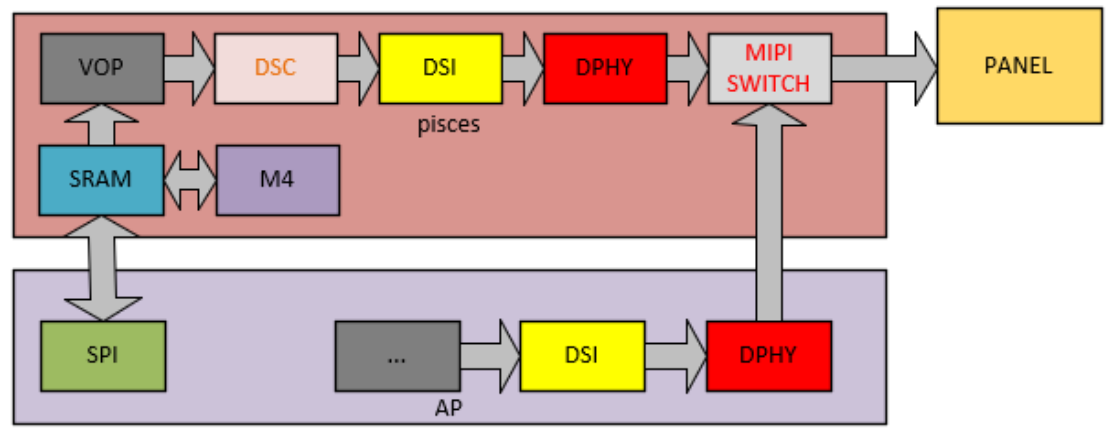
RK2108 display pipeline
For other platforms, see the display-pipeline description in Rockchip_Developer_Guide_DRM_Display_Driver_CN.
2. Software architecture
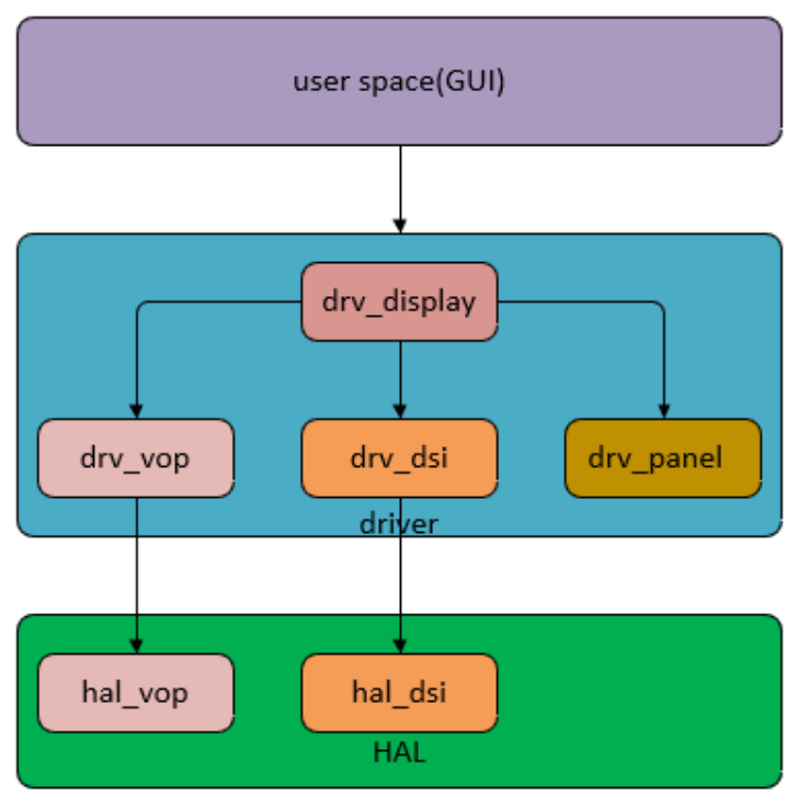
Display software architecture
2.1 Driver-layer files
| Driver | File | Description |
|---|---|---|
| Core | bsp/rockchip-common/drivers/drv_display.c | RT-Thread display framework: registers the display driver, loads display modules, connects applications and drivers and manages all display modules. |
| VOP | bsp/rockchip-common/drivers/drv_vop.c dsp/rockchip-common/drivers/drv_vop.h |
VOP display-module driver |
| DSI | bsp/rockchip-common/drivers/drv_dsi.c bsp/rockchip-common/drivers/drv_dsi.h |
DSI/DPHY display-module driver |
| PANEL | bsp/rockchip-common/drivers/drv_panel.c bsp/rockchip-common/drivers/drv_panel_cfg.h |
Panel driver abstracting initialization commands, timing, power management and other panel operations. |
2.2 HAL-layer files
| Driver | File | Description |
|---|---|---|
| Core | bsp/rockchip-common/hal/lib/hal/inc/hal_display.h | Basic display data-structure definitions |
| VOP | bsp/rockchip-common/hal/lib/hal/src/hal_vop.c bsp/rockchip-common/hal/lib/hal/inc/hal_vop.h |
VOP hardware functions |
| DSI | bsp/rockchip-common/hal/lib/hal/src/hal_dsi.c bsp/rockchip-common/hal/lib/hal/inc/hal_dsi.h |
DSI/DPHY hardware functions |
3. Common interfaces
RT-Thread GUI applications interact with drivers through control operations, similar to Linux IOCTL. The extended controls include:
| Parameter | Description |
|---|---|
| RK_DISPLAY_CTRL_ENABLE | Enable display device |
| RK_DISPLAY_CTRL_DISABLE | Disable display device |
| RK_DISPLAY_CTRL_SET_PLANE | Set the specified layer |
| RK_DISPLAY_CTRL_SET_SCALE | Set post-scaling |
| RK_DISPLAY_CTRL_LOAD_LUT | Configure the bpp lookup table |
| RK_DISPLAY_CTRL_SET_COLOR_MATRIX | Set color-conversion matrix |
| RK_DISPLAY_CTRL_SET_GAMMA_COE | Set gamma coefficients |
| RK_DISPLAY_CTRL_SET_BCSH | Set BCSH coefficients for brightness, contrast, saturation and hue |
| RK_DISPLAY_CTRL_SET_POST_CLIP | Set clip coefficient |
| RK_DISPLAY_CTRL_MIPI_SWITCH | Switch the MIPI switch path |
| Parameter | Description |
|---|---|
| RK_DISPLAY_CTRL_COMMIT | Update display configuration |
4. Key data structures
4.1 struct display_state
The central display-driver structure includes RTT device and graphic_info structures and Rockchip hardware abstractions.
| Parameter | Description |
|---|---|
| struct rt_device_graphic_info graphic_info | RTT display-device information structure |
| struct rt_device lcd | LCD device structure |
| uint32_t *rtt_framebuffer | RTT framebuffer address |
| struct crtc_state crtc_state | Rockchip VOP display controller |
| struct connector_state conn_state | Rockchip MIPI DSI display-conversion module |
| struct panel_state panel_state | Panel initialization commands, power and related information |
| struct DISPLAY_MODE_INFO mode | Scan timing and other panel information |
4.2 struct crtc_state
Describes the Rockchip processor VOP module, with the following main fields:
| Parameter | Description |
|---|---|
| struct VOP_REG *hw_base | VOP register base address |
| const struct rockchip_crtc_funcs *funcs | Function pointers implementing basic VOP operations |
| struct CRTC_WIN_STATE win_state | WIN layer structure |
| struct VOP_POST_SCALE_INFO post_scale | Post-scaling information |
| uint8_t irqno | VOP interrupt number |
| uint8_t power_state | Power state |
4.3 struct CRTC_WIN_STATE
Describes a WIN layer of the Rockchip VOP module:
| Parameter | Description |
|---|---|
| bool winEn | Layer enable: 0 off, 1 on |
| uint8_t winId | Layer selection: 0,1,2 mean win0,win1,win2 |
| uint8_t zpos | Layer Z order: 0,1,2 from bottom to top |
| uint8_t format | Format; available values in rt-thread/include/rtdef.h |
| uint32_t yrgbAddr | RGBX address or Y component address of YUV |
| uint32_t cbcrAddr | YUV UV component address |
| uint16_t xVir | Virtual width; 4Byte alignment required |
| uint16_t srcX | Layer X display position on panel |
| uint16_t srcY | Layer Y display position on panel |
| uint16_t srcW | Layer display width |
| uint16_t srcH | Layer display height |
| uint8_t hwFormat | Converted hardware setting; no application configuration needed |
| uint16_t hwCrtcX | Converted hardware setting; no application configuration needed |
| uint16_t hwCrtcY | Converted hardware setting; no application configuration needed |
| uint16_t xLoopOffset | X loop configuration |
| uint16_t yLoopOffset | Y loop configuration |
| bool alphaEn | Alpha enable |
| uint8_t alphaMode | Global alpha: VOP_ALPHA_MODE_USER_DEFINED; per-pixel alpha: VOP_ALPHA_MODE_PER_PIXEL |
| uint8_t alphaPreMul | Premultiplied alpha: YES VOP_PREMULT_ALPHA; NO VOP_NON_PREMULT_ALPHA |
| uint8_t alphaSatMode | Modify alpha: 1 means alpha = alpha + alpha[7]; 0 unchanged. Recommended 0. |
| uint8_t globalAlphaValue | Global alpha value: 0~0xff |
| uint32_t *lut | bpp lookup table; see display_test.c or provide a custom table |
4.4 struct VOP_POST_SCALE_INFO
Describes post-scaling in the Rockchip VOP module:
| Parameter | Description |
|---|---|
| uint16_t srcW | Source X resolution |
| uint16_t srcH | Source Y resolution |
| uint16_t dstX | Scaled X display position |
| uint16_t dstY | Scaled Y display position |
| uint16_t dstW | Scaled display width |
| uint16_t dstH | Scaled display height |
| bool postScaleEn | Hardware scaling enable; driver decides, application need not set it |
| eVOP_PostSclMode postSclHmode | Hardware scale factor computed by driver; no application setting |
| eVOP_PostSclMode postSclVmode | Hardware scale factor computed by driver; no application setting |
4.5 struct VOP_BCSH_INFO
Describes the VOP post-BCSH stage:
| Parameter | Description |
|---|---|
| uint8_t brightness | Brightness: 0~100, default 50 |
| uint8_t contrast | Contrast: 0~100, default 50 |
| uint8_t satCon | Saturation: 0~100, default 50 |
| uint8_t hue | Hue: 0~100, default 50 |
4.6 struct VOP_COLOR_MATRIX_INFO
Describes the VOP post color-matrix stage:
| Parameter | Description |
|---|---|
| bool colorMatrixEn | Enable switch |
| uint8_t *colorMatrixCoe | Conversion matrix coefficients |
| uint8_t *colorMatrixOffset | Conversion matrix offsets |

Original color conversion matrix
[csc_out0]   [csc_in0]   [coe00 coe01 coe02]   [offset0]
[csc_out1] = [csc_in1] X [coe10 coe11 coe12] + [offset1]
[csc_out2]   [csc_in2]   [coe20 coe21 coe22]   [offset2]
Example: bt709tobt2020 conversion matrix:
{0.6274, 0.3293, 0.0433},
{0.0691, 0.9195, 0.0114},
{0.0164, 0.0880, 0.8956}
After fixed-point conversion using 0x80 (bit7 is the sign bit):
coe00 = 0.6274 * 0x80  = 0x50
coe01 = 0.3293 * 0x80  = 0x2a
coe02 = 0.0433 * 0x80  = 0x05
Similarly, the source gives:
colorMatrixCoe[3][3] = {
    {0x50, 0x2a, 0x05},
    {0x05, 0x75, 0x02},
    {0x02, 0x08, 0x72}
};
4.7 struct VOP_POST_CLIP_INFO
Describes the VOP post-clip stage:
| Parameter | Description |
|---|---|
| bool postClipEn | Enable switch |
| uint8_t postYThres | Value to clip |
5. Alignment requirements
5.1 Data alignment
RK2108
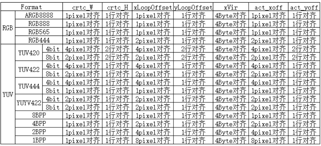
RK2108 data alignment
| Format | crtc W (pixel alignment) | crtc H (line alignment) | xLoopOffset (pixels) | yLoopOffset (lines) | xVir (bytes) | act_xoff (pixels) | act_yoff (lines) |
|---|---|---|---|---|---|---|---|
| RGB ARGB8888 | 1 | 1 | 1 | 1 | 4 | 1 | 1 |
| RGB RGB888 | 1 | 1 | 1 | 1 | 4 | 1 | 1 |
| RGB RGB565 | 1 | 1 | 1 | 1 | 4 | 1 | 1 |
| RGB RGB444 | 1 | 1 | 2 | 1 | 4 | 2 | 1 |
| YUV YUV420 4bit | 4 | 2 | 4 | 2 | 4 | 4 | 2 |
| YUV YUV420 8bit | 2 | 2 | 2 | 2 | 4 | 2 | 2 |
| YUV YUV422 4bit | 4 | 1 | 4 | 1 | 4 | 4 | 1 |
| YUV YUV422 8bit | 2 | 1 | 2 | 1 | 4 | 2 | 1 |
| YUV YUV444 4bit | 4 | 1 | 4 | 1 | 4 | 4 | 1 |
| YUV YUV444 8bit | 1 | 1 | 1 | 1 | 4 | 1 | 1 |
| YUV YUVY422 4bit | 2 | 1 | 2 | 1 | 4 | 2 | 1 |
| YUV YUVY422 8bit | 2 | 1 | 2 | 1 | 4 | 2 | 1 |
| 8BPP | 1 | 1 | 1 | 1 | 4 | 1 | 1 |
| 4BPP | 1 | 1 | 2 | 1 | 4 | 2 | 1 |
| 2BPP | 1 | 1 | 4 | 1 | 4 | 4 | 1 |
| 1BPP | 1 | 1 | 8 | 1 | 4 | 8 | 1 |
5.2 Panel alignment
Some panels impose alignment requirements. For S6E3HC2 at 1440x3120, the DSC slice is 720x65: partial-refresh position must align to 720x65 and the display-region size to 720x195. At 720x1560, the slice is 360x52: position must align to 360x52 and region size to 360x390.
6. Panel configuration
6.1 Select a supported panel
Select the panel configuration through this menu:
cd bsp/rockchip-pisces
    scons --menuconfig
        RT-Thread rockchip common drivers  --->
            Panel Type (R17 SS mipi panel, resolution is 1080x2340)  --->
6.2 Add a new panel
-
Enter the configuration directory:
cd bsp/rockchip-common/drivers/panel_cfg. -
Copy an existing .h file to new_panel.h and modify its parameters using section 6.4 and the panel specification.
-
Return with
cd ../to bsp/rockchip-common/drivers/. -
Open Kconfig, find “Panel Type” and define RT_USING_PANEL_NEW_PANEL following the existing config RT_USING_PANEL entries.
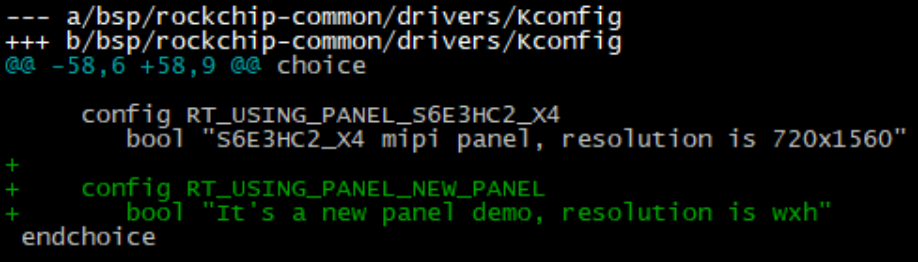
Kconfig new-panel example
--- a/bsp/rockchip-common/drivers/Kconfig
+++ b/bsp/rockchip-common/drivers/Kconfig
@@ -58,6 +58,9 @@ choice

     config RT_USING_PANEL_S6E3HC2_X4
        bool "S6E3HC2_X4 mipi panel, resolution is 720x1560"
+
+    config RT_USING_PANEL_NEW_PANEL
+       bool "It's a new panel demo, resolution is wxh"
 endchoice
6.3 Typical scan timing
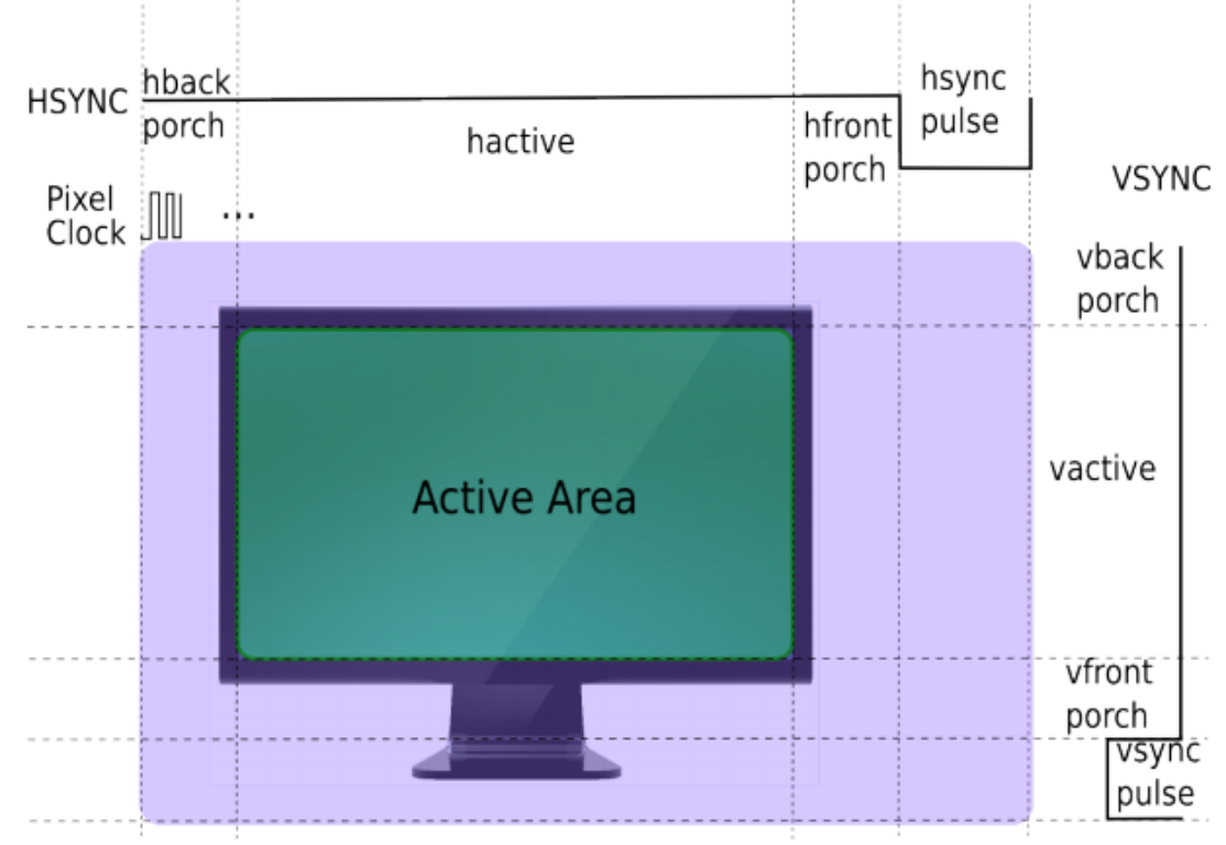
Display scan timing
6.4 Panel configuration parameters
| Parameter | Description |
|---|---|
| RT_HW_LCD_XRES | Horizontal resolution; hactive in section 6.3 |
| RT_HW_LCD_YRES | Vertical resolution; vactive in section 6.3 |
| RT_HW_LCD_PIXEL_CLOCK | Pixel clock, khz |
| RT_HW_LCD_LANE_MBPS | MIPI DPHY CLK Lane clock, Mbps |
| RT_HW_LCD_LEFT_MARGIN | Left blanking; hback-porch in section 6.3 |
| RT_HW_LCD_RIGHT_MARGIN | Right blanking; hfront-porch in section 6.3 |
| RT_HW_LCD_UPPER_MARGIN | Upper blanking; vback-porch in section 6.3 |
| RT_HW_LCD_LOWER_MARGIN | Lower blanking; vfront-porch in section 6.3 |
| RT_HW_LCD_HSYNC_LEN | Horizontal sync duration; source calls it hsync-porch in section 6.3 |
| RT_HW_LCD_VSYNC_LEN | Vertical sync duration; source calls it vsync-porch in section 6.3 |
| RT_HW_LCD_CONN_TYPE | Panel type, e.g. RK_DISPLAY_CONNECTOR_DSI |
| RT_HW_LCD_BUS_FORMAT | Panel bus format, e.g. MEDIA_BUS_FMT_RGB888_1X24 |
| RT_HW_LCD_VMODE_FLAG | Polarity, DSC support and related flags |
| RT_HW_LCD_INIT_CMD_TYPE | Command type; CMD_TYPE_DEFAULT defaults to MIPI CMD |
| RT_HW_LCD_DISPLAY_MODE | Select CMD or video mode |
| RT_HW_LCD_AREA_DISPLAY | Partial-refresh support |
| RT_HW_LCD_XACT_ALIGN | Display-region width alignment in pixels |
| RT_HW_LCD_YACT_ALIGN | Display-region height alignment in pixels |
| Parameter | Description |
|---|---|
| RT_HW_LCD_XPOS_ALIGN | Display-region X-position alignment in pixels |
| RT_HW_LCD_YPOS_ALIGN | Display-region Y-position alignment in pixels |
| RT_HW_LCD_PREPARE_DELAY_MS | Time until panel is ready to receive image data, ms |
| RT_HW_LCD_UNPREPARE_DELAY_MS | Time until panel is fully powered off, ms |
| RT_HW_LCD_ENABLE_DELAY_MS | Time from ready to normal image display, ms |
| RT_HW_LCD_DISABLE_DELAY_MS | Time to leave normal image-display state, ms |
| RT_HW_LCD_INIT_DELAY_MS | Time from reset until initialization commands can be sent, ms |
| RT_HW_LCD_RESET_DELAY_MS | Time required for a complete panel reset, ms |
| struct rockchip_cmd cmd_on[] | Panel initialization commands |
| struct rockchip_cmd cmd_off[] | Panel deinitialization commands |
| struct rockchip_cmd cmd_aod_on[] | Commands to enter AOD |
| struct rockchip_cmd cmd_aod_off[] | Commands to exit AOD |
6.5 Panel initialization commands
- MIPI DSI CMD example:
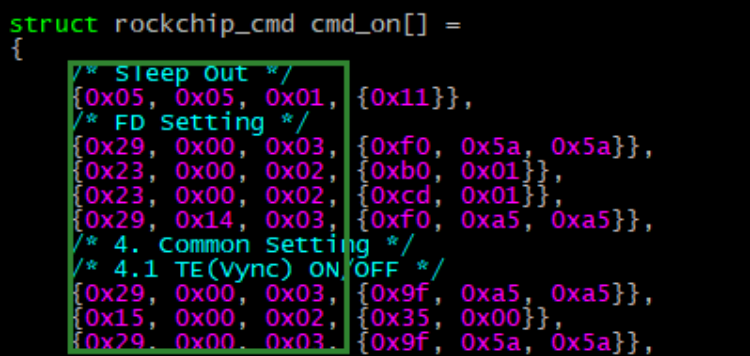
Initialization command screenshot excerpt
struct rockchip_cmd cmd_on[] =
{
    /* sleep out */
    {0x05, 0x05, 0x01, {0x11}},
    /* FD Setting */
    {0x29, 0x00, 0x03, {0xf0, 0x5a, 0x5a}},
    {0x23, 0x00, 0x02, {0xb0, 0x01}},
    {0x23, 0x00, 0x02, {0xcd, 0x01}},
    {0x29, 0x14, 0x03, {0xf0, 0xa5, 0xa5}},
    /* 4. Common Setting */
    /* 4.1 TE(Vync) ON/OFF */
    {0x29, 0x00, 0x03, {0x9f, 0xa5, 0xa5}},
    {0x15, 0x00, 0x02, {0x35, 0x00}},
    {0x29, 0x00, 0x03, {0x9f, 0x5a, 0x5a}},
The first three hexadecimal bytes are Data Type, Delay and Payload Length. From the fourth byte, the actual payload contains Payload Length bytes.
- First-command decoding:

First initialization command
/* sleep out */
{0x05, 0x05, 0x01, {0x11}},
Data Type: 0x05 (DCS Short Write)
Delay: 0x05 (5 ms)
Payload Length: 0x01 (1 byte)
Payload: 0x11
- Second-command decoding:

Second initialization command
/* FD Setting */
{0x29, 0x00, 0x03, {0xf0, 0x5a, 0x5a}},
Data Type: 0x29 (Generic Long Write)
Delay: 0x00 (0 ms)
Payload Length: 0x03 (3 bytes)
Payload: 0xf0 0x5a 0x5a
- Data Type definitions
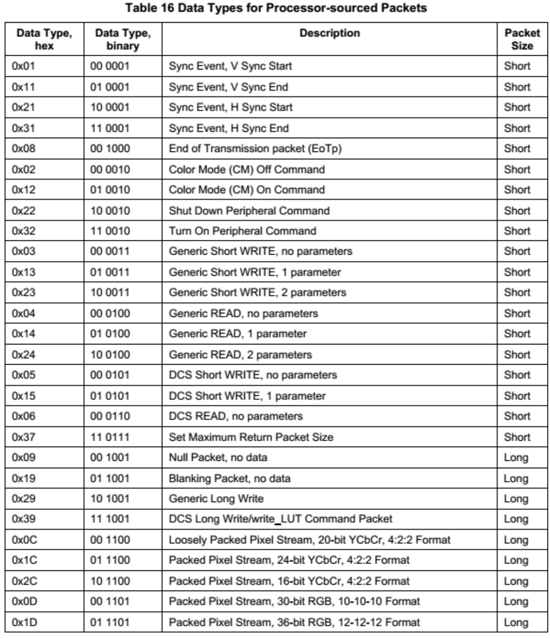
Processor-sourced packet types
| Data Type (hex) | Data Type (binary) | Description | Packet size |
|---|---|---|---|
| 0x01 | 00 0001 | V Sync Start | Short |
| 0x11 | 01 0001 | V Sync End | Short |
| 0x21 | 10 0001 | H Sync Start | Short |
| 0x31 | 11 0001 | H Sync End | Short |
| 0x08 | 00 1000 | End of Transmission packet (EoTp) | Short |
| 0x02 | 00 0010 | Color Mode (CM) Off Command | Short |
| 0x12 | 01 0010 | Color Mode (CM) On Command | Short |
| 0x22 | 10 0010 | Shut Down Peripheral Command | Short |
| 0x32 | 11 0010 | Turn On Peripheral Command | Short |
| 0x03 | 00 0011 | Generic Short WRITE, no parameters | Short |
| 0x13 | 01 0011 | Generic Short WRITE, 1 parameter | Short |
| 0x23 | 10 0011 | Generic Short WRITE, 2 parameters | Short |
| 0x04 | 00 0100 | Generic READ, no parameters | Short |
| 0x14 | 01 0100 | Generic READ, 1 parameter | Short |
| 0x24 | 10 0100 | Generic READ, 2 parameters | Short |
| 0x05 | 00 0101 | DCS Short WRITE, no parameters | Short |
| 0x15 | 01 0101 | DCS Short WRITE, 1 parameter | Short |
| 0x06 | 00 0110 | DCS READ, no parameters | Short |
| 0x37 | 11 0111 | Set Maximum Return Packet Size | Short |
| 0x09 | 00 1001 | Null Packet, no data | Long |
| 0x19 | 01 1001 | Blanking Packet, no data | Long |
| 0x29 | 10 1001 | Generic Long Write | Long |
| 0x39 | 11 1001 | DCS Long Write/write_LUT Command Packet | Long |
| 0x0C | 00 1100 | Loosely Packed Pixel Stream, 20-bit YCbCr, 4:2:2 Format | Long |
| 0x1C | 01 1100 | Packed Pixel Stream, 24-bit YCbCr, 4:2:2 Format | Long |
| 0x2C | 10 1100 | Packed Pixel Stream, 16-bit YCbCr, 4:2:2 Format | Long |
| 0x0D | 00 1101 | Packed Pixel Stream, 30-bit RGB, 10-10-10 Format | Long |
| 0x1D | 01 1101 | Packed Pixel Stream, 36-bit RGB, 12-12-12 Format | Long |
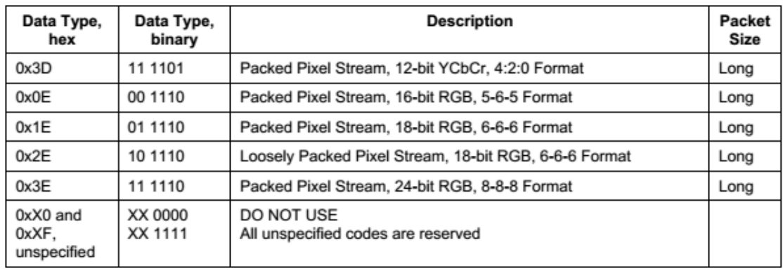
Packet types continued
| Data Type (hex) | Data Type (binary) | Description | Packet size |
|---|---|---|---|
| 0x3D | 11 1101 | Packed Pixel Stream, 12-bit YCbCr, 4:2:0 Format | Long |
| 0x0E | 00 1110 | Packed Pixel Stream, 16-bit RGB, 5-6-5 Format | Long |
| 0x1E | 01 1110 | Packed Pixel Stream, 18-bit RGB, 6-6-6 Format | Long |
| 0x2E | 10 1110 | Loosely Packed Pixel Stream, 18-bit RGB, 6-6-6 Format | Long |
| 0x3E | 11 1110 | Packed Pixel Stream, 24-bit RGB, 8-8-8 Format | Long |
| 0xX0 / 0xXF / unspecified | XX 0000 / XX 1111 | DO NOT USE. All unspecified codes are reserved. |
- DCS Write

DCS Write types
| Data Type (hex) | Data Type (binary) | Description | Packet size |
|---|---|---|---|
| 0x05 | 00 0101 | DCS Short WRITE, no parameters | Short |
| 0x15 | 01 0101 | DCS Short WRITE, 1 parameter | Short |
| 0x39 | 11 1001 | DCS Long Write/write_LUT Command Packet | Long |
A DCS packet contains one DCS-command byte and n parameter bytes. For n < 2, use a Short Packet: n=0 sends only the command with Data Type 0x05; n=1 sends one parameter with Data Type 0x15. For n >= 2, use a Long Packet containing the command and n parameters, Data Type 0x39.
- Generic Write

Generic Write types
| Data Type (hex) | Data Type (binary) | Description | Packet size |
|---|---|---|---|
| 0x03 | 00 0011 | Generic Short WRITE, no parameters | Short |
| 0x13 | 01 0011 | Generic Short WRITE, 1 parameter | Short |
| 0x23 | 10 0011 | Generic Short WRITE, 2 parameters | Short |
| 0x29 | 10 1001 | Generic Long Write | Long |
A Generic Packet contains n parameter bytes. For n < 3, use a Short Packet: n=0 has no parameters, Data Type 0x03; n=1 has one parameter, 0x13; n=2 has two parameters, 0x23. For n >= 3, use a Long Packet with n parameters, Data Type 0x29.
-
Delay specifies the wait in ms after sending the current packet and before the next command.
-
Payload Length is the packet payload length.
-
Payload is the packet’s actual data, of length Payload Length.
-
Example
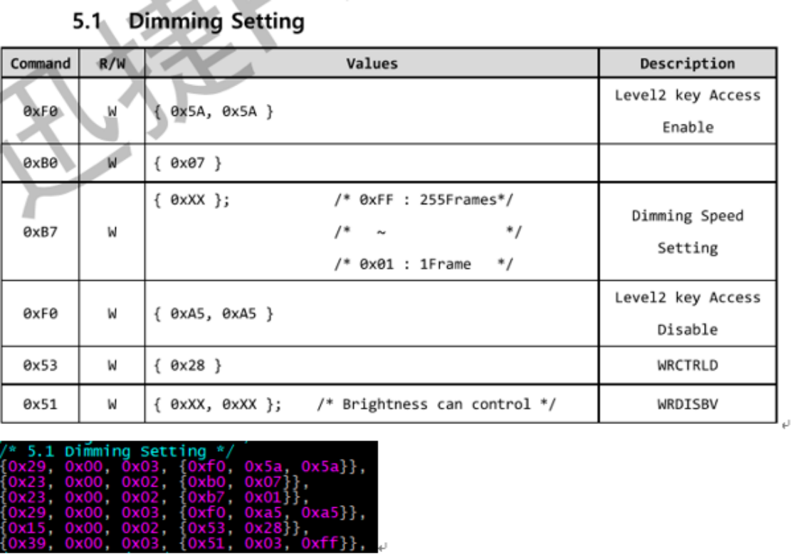
Dimming settings and commands
| Command | R/W | Values | Description |
|---|---|---|---|
| 0xF0 | W | { 0x5A, 0x5A } | Level2 key access enable |
| 0xB0 | W | { 0x07 } | |
| 0xB7 | W | { 0xXX }; /* 0xFF : 255Frames; ~; 0x01 : 1Frame */ | Dimming speed setting |
| 0xF0 | W | { 0xA5, 0xA5 } | Level2 key access disable |
| 0x53 | W | { 0x28 } | WRCTRLD |
| 0x51 | W | { 0xXX, 0xXX }; /* Brightness can control */ | WRDISBV |
/* 5.1 Dimming Setting */
{0x29, 0x00, 0x03, {0xf0, 0x5a, 0x5a}},
{0x23, 0x00, 0x02, {0xb0, 0x07}},
{0x23, 0x00, 0x02, {0xb7, 0x01}},
{0x29, 0x00, 0x03, {0xf0, 0xa5, 0xa5}},
{0x15, 0x00, 0x02, {0x53, 0x28}},
{0x39, 0x00, 0x03, {0x51, 0x03, 0xff}},
7. display_test tool
display_test applies only to RK2108. Other platforms must use modetest, described below, to test display functions.
7.1 Supported test cases
Command:
display_test cmd
dsc; winloop; winmove; winalpha; scale; coe;  bcsh; gamma; clip; mipi_switch;
ebook; color_bar
| Parameter | Description |
|---|---|
| winloop | Test layer loop |
| winmove | Test layer movement |
| dsc | Test partial refresh with 2k-panel DSC alignment |
| winalpha | Test layer alpha |
| scale | Test post-scaling |
| coe | Test color conversion; demo uses 709to2020 |
| bcsh | Test brightness, contrast, saturation and hue through BCSH |
| gamma | Change display effect through a gamma curve |
| clip | Test clip |
| mipi_switch | Test MIPI switch |
| ebook | E-book demo displaying a 1bpp image |
| color_bar | Demo displaying looping color bars |
7.2 Demo walkthrough
- Find the LCD device.
g_display_dev = rt_device_find("lcd");
RT_ASSERT(g_display_dev != RT_NULL);
- Open the LCD device.
ret = rt_device_open(g_display_dev, RT_DEVICE_FLAG_RDWR);
RT_ASSERT(ret == RT_EOK);
- Enable the LCD device.
ret = rt_device_control(g_display_dev, RK_DISPLAY_CTRL_ENABLE, NULL);
RT_ASSERT(ret == RT_EOK);
- Obtain panel information.
ret = rt_device_control(g_display_dev, RTGRAPHIC_CTRL_GET_INFO, (void *)graphic_info);
RT_ASSERT(ret == RT_EOK);
- Initialize win_config and post_scale. Initialize win_config as follows:
static void display_win_init(struct CRTC_WIN_STATE *win_config)
{
    win_config->winEn = true;
    win_config->winId = 0;
    win_config->zpos  = 0;
    win_config->format   = SRC_DATA_FMT;
    win_config->yrgbAddr = (uint32_t)rtt_framebuffer_test;
    win_config->cbcrAddr = (uint32_t)rtt_framebuffer_uv;
    win_config->yrgbLength = 0;
    win_config->cbcrLength = 0;
    win_config->xVir = SRC_DATA_W;
    win_config->srcX = 0;
    win_config->srcY = 0;
    win_config->srcW = SRC_DATA_W;
    win_config->srcH = SRC_DATA_H;
    win_config->crtcX = 0;
    win_config->crtcY = 0;
    win_config->crtcW = SRC_DATA_W;
    win_config->crtcH = SRC_DATA_H;
    win_config->xLoopOffset = 0;
    win_config->yLoopOffset = 0;
}
Initialize post_scale for fullscreen display without scaling:
static void display_post_init(struct CRTC_WIN_STATE *win_config,
                              struct VOP_POST_SCALE_INFO *post_scale,
                              struct rt_device_graphic_info *graphic_info)
{
    post_scale->srcW = graphic_info->width;
    post_scale->srcH = graphic_info->height;
    post_scale->dstX = 0;
    post_scale->dstY = 0;
    post_scale->dstW = graphic_info->width;
    post_scale->dstH = graphic_info->height;
}
Initialize post_scale for partial refresh with 2x horizontal and vertical scaling:
static void display_post_init(struct CRTC_WIN_STATE *win_config,
                              struct VOP_POST_SCALE_INFO *post_scale,
                              struct rt_device_graphic_info *graphic_info)
{
    post_scale->srcW = graphic_info->width / 2;
    post_scale->srcH = win_config->srcH;
    post_scale->dstX = 0;
    post_scale->dstY = 0;
    post_scale->dstW = graphic_info->width;
    post_scale->dstH = win_config->srcH * 2;
}
- Load the LUT palette for bpp images; skip this step for other formats.
ret = rt_device_control(g_display_dev, RK_DISPLAY_CTRL_LOAD_LUT, &lut_state);
RT_ASSERT(ret == RT_EOK);
- Configure post_scale with the data dimensions before scaling and displayed dimensions afterward.
ret = rt_device_control(g_display_dev, RK_DISPLAY_CTRL_SET_SCALE, post_scale);
RT_ASSERT(ret == RT_EOK);
- Configure win_config layer information.
ret = rt_device_control(g_display_dev, RK_DISPLAY_CTRL_SET_PLANE, win_config);
RT_ASSERT(ret == RT_EOK);
- Commit the display.
ret = rt_device_control(g_display_dev, RK_DISPLAY_CTRL_COMMIT, NULL);
RT_ASSERT(ret == RT_EOK);
Display one frame using steps 1–9. For multiple frames, modify win_config and post_scale, then repeat steps 7, 8 and 9.
7.3 Partial-refresh coordinates
- Demo for panels supporting partial refresh in both X and Y.
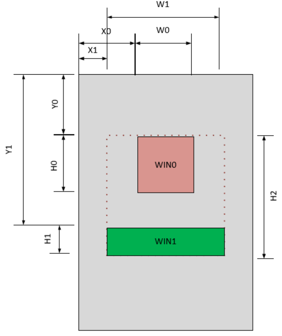
XY partial-refresh coordinates
The red region is win0 at (X0,Y0), size (W0,H0). Configure:
win_config->winId = 0;
win_config->winEn = 1;
……
win_config->srcX = X0;
win_config->srcY = Y0;
win_config->srcW = W0;
win_config->srcH = H0;
The green region is win1 at (X1,Y1), size (W1,H1). Configure:
win_config->winId = 1;
win_config->winEn = 1;
……
win_config->srcX = X1;
win_config->srcY = Y1;
win_config->srcW = W1;
win_config->srcH = H1;
Post-scaling configuration:
post_scale->srcW = W1;
post_scale->srcH = H2;
post_scale->dstX = X1;
post_scale->dstY = Y0;
post_scale->dstW = W1;
post_scale->dstH = H2;
In the actual display code, configure post-scaling first:
ret = rt_device_control(g_display_dev, RK_DISPLAY_CTRL_SET_SCALE, post_scale);
RT_ASSERT(ret == RT_EOK);
Then configure WIN0 and WIN1:
ret = rt_device_control(g_display_dev, RK_DISPLAY_CTRL_SET_PLANE, win_config);
RT_ASSERT(ret == RT_EOK);
Finally commit the display:
ret = rt_device_control(g_display_dev, RK_DISPLAY_CTRL_COMMIT, NULL);
RT_ASSERT(ret == RT_EOK);
- Demo for Y-only partial refresh, without X support.
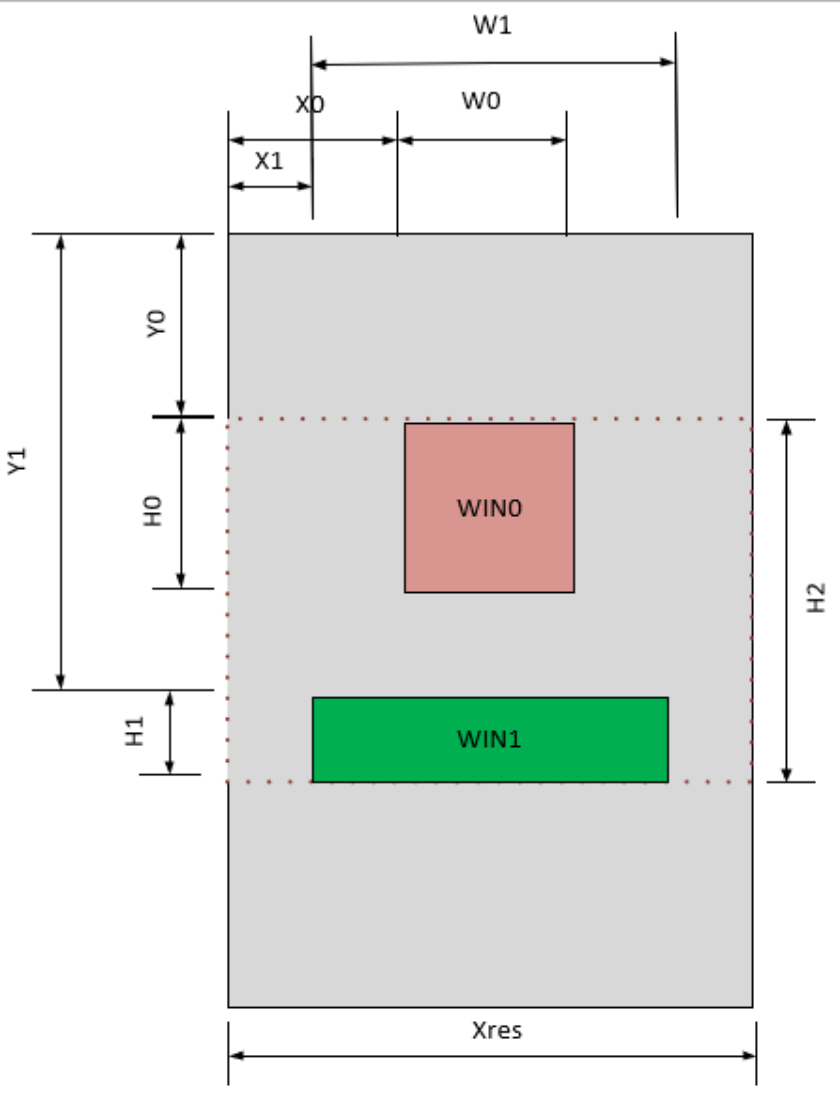
Y-only partial-refresh coordinates
The red region is win0 at (X0,Y0), size (W0,H0). Configure:
win_config->winId = 0;
win_config->winEn = 1;
……
win_config->srcX = X0;
win_config->srcY = Y0;
win_config->srcW = W0;
win_config->srcH = H0;
The green region is win1 at (X1,Y1), size (W1,H1). Configure:
win_config->winId = 1;
win_config->winEn = 1;
……
win_config->srcX = X1;
win_config->srcY = Y1;
win_config->srcW = W1;
win_config->srcH = H1;
Post-scaling configuration:
post_scale->srcW = Xres;
post_scale->srcH = H2;
post_scale->dstX = 0;
post_scale->dstY = Y0;
post_scale->dstW = Xres;
post_scale->dstH = H2;
Without X partial refresh, unlike case 1, the post-scale source width and dstW are the actual panel width Xres, and dstX is 0. Other steps match case 1. Configure post-scaling first:
ret = rt_device_control(g_display_dev, RK_DISPLAY_CTRL_SET_SCALE, post_scale);
RT_ASSERT(ret == RT_EOK);
Then configure WIN0 and WIN1:
ret = rt_device_control(g_display_dev, RK_DISPLAY_CTRL_SET_PLANE, win_config);
RT_ASSERT(ret == RT_EOK);
Finally commit the display:
ret = rt_device_control(g_display_dev, RK_DISPLAY_CTRL_COMMIT, NULL);
RT_ASSERT(ret == RT_EOK);
8. modetest tool
8.1 Supported test cases
modetest [-afgp]

        -p <plane_id>:<w>x<h>:<crtc_w>x<crtc_h>[+<x>+<y>][#<zpos>][@<format>]  set plane
        -f <pattern>    specify fill pattern
        -a      test alpha
        -g      test gamma
Example command:
modetest -p 0:720x1280:720x1280@AR24 -a -g
9. Color Key
VOP can make a selected color in a layer fully transparent, exposing the next layer or background. The driver uses win_config.colorKey: bits [23,0] contain the RGB key components, and bit24 enables/disables the function. The RGB888 and RGB565 examples below use R_VAL, G_VAL and B_VAL for the component values to make transparent.
#define COLOR_KEY_EN BIT(24)
9.1 RGB888 Color Key configuration
- Make red fully transparent:
win_config->colorKey = 0xFF0000 | COLOR_KEY_EN;
- Make green fully transparent:
win_config->colorKey = 0x00FF00 | COLOR_KEY_EN;
- Make blue fully transparent:
win_config->colorKey = 0x0000FF | COLOR_KEY_EN;
That is:
win_config->colorKey = (R_VAL << 16) | (G_VAL << 8) | (B_VAL) | COLOR_KEY_EN;
9.2 RGB565 Color Key configuration
- Make red fully transparent:
win_config->colorKey = 0xF80000 | COLOR_KEY_EN;
- Make green fully transparent:
win_config->colorKey = 0x00FC00 | COLOR_KEY_EN;
- Make blue fully transparent:
win_config->colorKey = 0x0000F8 | COLOR_KEY_EN;
That is:
R_VAL_CONFIG = R_VAL << 3;  //R[4,0] -> R[7,0]

G_VAL_CONFIG = G_VAL << 2;  //G[5,0] -> G[7,0]

B_VAL_CONFIG = B_VAL << 3;  //B[4,0] -> B[7,0]

win_config->colorKey = (R_VAL_CONFIG  << 16) | (G_VAL_CONFIG << 8) | B_VAL_CONFIG | COLOR_KEY_EN;
9.3 Disable Color Key
win_config->colorKey = 0;
10. Updating the LUT
Using a layer LUT requires lut_en. Once enabled, the LUT is protected and its registers cannot be read or written. Changing lut_en takes effect on a frame boundary. To update the LUT when switching scenarios, follow these steps:
- Disable the LUT. (1) Set a non-bpp layer format, excluding:
RTGRAPHIC_PIXEL_FORMAT_GRAY1
RTGRAPHIC_PIXEL_FORMAT_GRAY4,
RTGRAPHIC_PIXEL_FORMAT_GRAY16,
RTGRAPHIC_PIXEL_FORMAT_GRAY256,
RTGRAPHIC_PIXEL_FORMAT_RGB332,
(2) Disable all layers and refresh a 32x32 image where no content is displayed. 32x32 is not mandatory: the purpose is an ineffective frame that applies lut_en disable without affecting the current screen content.
-
Update the LUT array and call RK_DISPLAY_CTRL_LOAD_LUT.
-
Configure a new frame: set the win format to the corresponding bpp format and refresh one frame. The new LUT then takes effect.
11. References
-
Rockchip DRM Display Driver Development Guide
-
Rockchip_DRM_Panel_Porting_Guide.pdf