
ArmSoM applicability and source scope
This is a Rockchip platform reference, not an ArmSoM hardware validation report. It describes the RKISP module, overall camera workflow and related APIs for camera-driver debugging. The supplied source is Rockchip_Driver_Guide_VI_EN_v1.0.7.pdf, V1.0.7, 133 pages. No corresponding Chinese PDF was supplied: Chinese and Russian are complete translations of this English source, and all three editions use its original English figures.
The cover product table names RV1126/RV1109 with Linux 4.19; the following applicability table additionally includes RK3566/RK3568. Both are retained below. This does not establish compatibility with every ArmSoM board or BSP. Before adaptation, check the exact SoC, Linux 4.19 vendor SDK/BSP, ISP/ISPP/VICAP topology, camera connector, lane routing, sensor/VCM/flash power and clocks, DTS and IQ/AIQ version. No board-specific hardware testing was performed. All measurements, logs and commands below are source examples, not ArmSoM test results.
Source inconsistencies are not silently corrected: the capability tables on PDF pages 6 and 13 disagree on RK356x maximum resolution; several paragraphs say RV1106 whereas the product scope says RV1109. Source spellings such as hsync-acitve, pclk-ative, hieght and /dev/medio0 need checking against the target BSP. Follow the editorial record before applying examples. IOMMU disabling and clock increases in the latency section are source optimization examples, not blanket production recommendations.
Editorial notes · ArmSoM official documentation · Linux media userspace API
Original product scope (PDF page 1)
| Chip name | Kernel version |
|---|---|
| RV1126/RV1109 | Linux 4.19 |
Original applicability matrix (PDF page 2)
| Platform | Linux Kernel 4.19 |
|---|---|
| RV1126 | Y |
| RV1109 | Y |
| RK3566 | Y |
| RK3568 | Y |
VI difference of the chip
| SOC | VI IP | VI Interface | Bayer CIS max resolution |
Feature |
|---|---|---|---|---|
| RV1109 | ISP20 ( ISP + ISPP): 1 VICAP Full: 1 VICAP Lite: 1 |
MIPI DPHY: 2 x 4Lanes 2.5Gbps/Lane LVDS: 2 x 4Lanes 1.0Gbps/Lane DVP: BT601 / BT656 / BT1120 pclk: 150MHz |
3072x2048 | Upto 3 frames HDR |
| RK3566 | ISP21 Lite: 1 VICAP Full: 1 |
MIPI DPHY: 2 x 2Lanes or 1 x 4Lanes 2.5Gbps/Lane DVP: BT601 / BT656 / BT1120 pclk: 150MHz |
4096x2304 | No HDR |
| RK3568 | ISP21:1 VICAP Full: 1 |
MIPI DPHY: 2 x 2Lanes or 1 x 4Lanes 2.5Gbps/Lane DVP: BT601 / BT656 / BT1120 pclk: 150MHz |
4096x2304 | Upto 2 frames HDR |
| RV1126 | ISP20 ( ISP + ISPP): 1 VICAP Full: 1 VICAP Lite: 1 |
MIPI DPHY: 2 x 4Lanes 2.5Gbps/Lane LVDS: 2 x 4Lanes 1.0Gbps/Lane DVP: BT601 / BT656 / BT1120 pclk: 150MHz |
4416x3312 | Upto 3 frames HDR |
Camera software driver catalog description
Linux Kernel-4.19
-
arch/arm/boot/dts— DTS configuration file -
drivers/phy/rockchip -
drivers/phy/rockchip/phy-rockchip-mipi-rx.c— mipi dphy driver -
drivers/phy/rockchip/phy-rockchip-csi2-dphy-common.h -
drivers/phy/rockchip/phy-rockchip-csi2-dphy-hw.c -
drivers/phy/rockchip/phy-rockchip-csi2-dphy.c -
drivers/media -
drivers/media/platform/rockchip/cif -
drivers/media/platform/rockchip/isp -
drivers/media/platform/rockchip/isp/dev— Including probe, asynchronous registration, clock, pipeline, iommu and media/v4l2 framework -
drivers/media/platform/rockchip/isp/capture— Including mp/sp/rawwr configuration and vb2, frame interrupt processing -
drivers/media/platform/rockchip/isp/dmarx— Including rawrd configuration and vb2, frame interrupt processing -
drivers/media/platform/rockchip/isp/isp_params— 3A related parameter settings -
drivers/media/platform/rockchip/isp/isp_stats— 3A related statistics -
drivers/media/platform/rockchip/isp/isp_mipi_luma— mipi data brightness statistics -
drivers/media/platform/rockchip/isp/regs— Register-related read and write operations -
drivers/media/platform/rockchip/isp/rkisp— isp subdev and entity registration -
drivers/media/platform/rockchip/isp/csi— csi subdev and mipi configuration -
drivers/media/platform/rockchip/isp/bridge— bridge subdev, isp and ispp interactive bridge -
drivers/media/platform/rockchip/ispp -
drivers/media/platform/rockchip/ispp/dev— Including probe, asynchronous registration, clock, pipeline, iommu and media/v4l2 framework -
drivers/media/platform/rockchip/ispp/stream— Including 4 video output configuration and vb2, frame interrupt processing -
drivers/media/platform/rockchip/ispp/rkispp— ispp subdev and entity registration -
drivers/media/platform/rockchip/ispp/params— TNR/NR/SHP/FEC/ORB parameter setting -
drivers/media/platform/rockchip/ispp/stats— ORB statistics -
drivers/media/i2c -
drivers/media/i2c/os04a10.c— CIS (cmos image sensor) driver
Link relationship between ISP and VICAP
For the RV1126/RV1109 and RK356X platforms, VICAP and ISP are two independent image processing IPs. If the images collected by VICAP are processed by ISP, the v4l2 sub device of the VICAP corresponding interface needs to be generated at the driver level to link to the node corresponding to the ISP. , To provide parameters for the ISP driver to use. Please refer to RKISP driver for ISP driver description and RKVICAP driver for VICAP driver description. The overall block diagram of the specific VICAP interfaces and the ISP link is as follows:
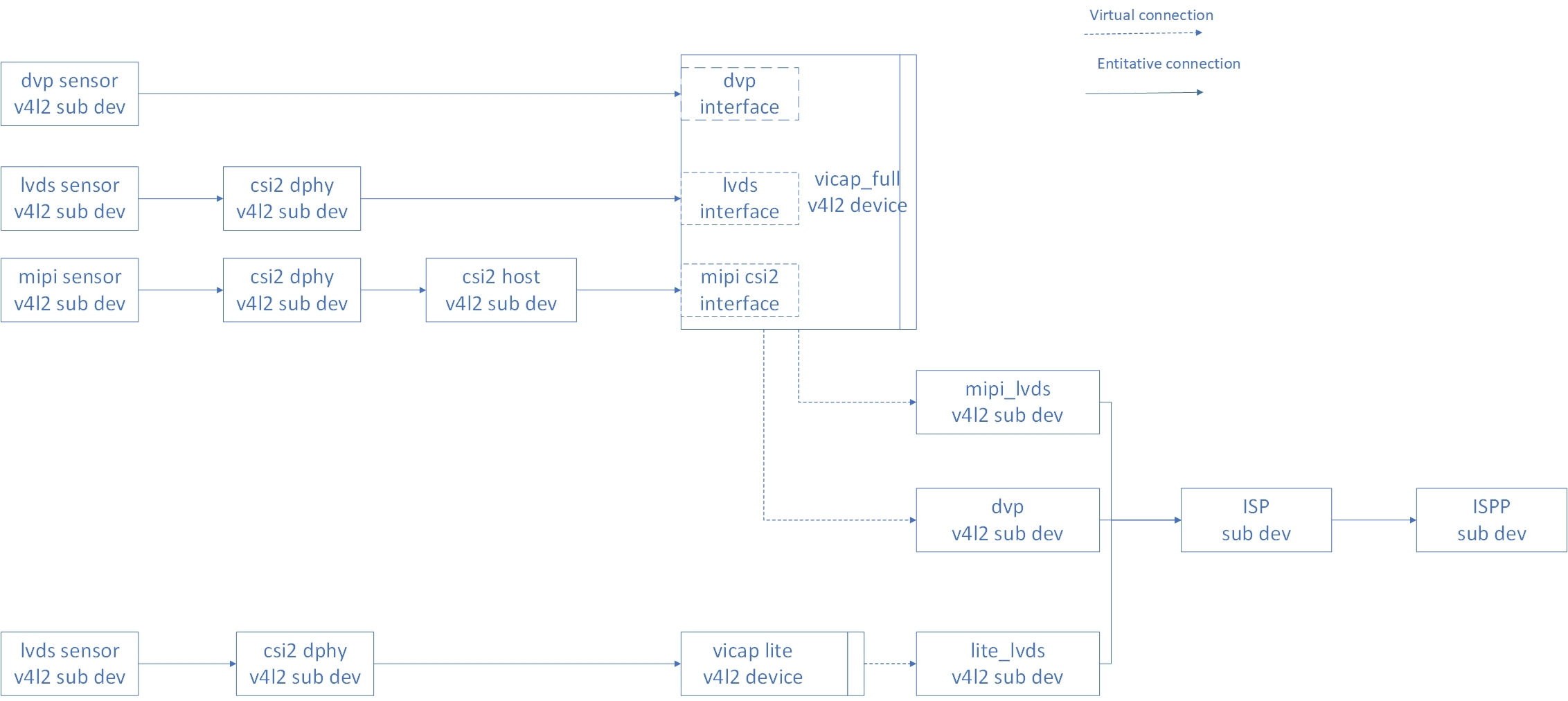
Original English figure 1, PDF page 7
RKISP driver
Brief description of the framework
The RKISP driver is mainly based on the v4l2/media framework to implement hardware configuration, interrupt processing, control buffer rotation, and control the power on and off of subdevices (such as MIPI DPHY and sensor).
The following block diagram describes the topology of the RKISP driver:
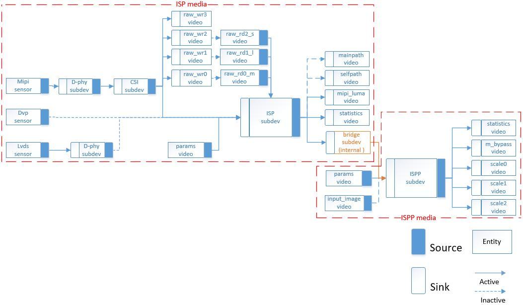
Original English figure 2, PDF page 8
| Name | Type | Description |
|---|---|---|
| rkisp_mainpath | v4l2_vdevcapture | Format: YUV, RAW Bayer; Support: Crop |
| rkisp_selfpath | v4l2_vdevcapture | Format: YUV, RGB; Support: Crop |
| rkisp-isp-subdev | v4l2_subdev | Internal isp blocks; Support: source/sink pad crop. The format on sink pad equal to sensor input format, the size equal to sensor input size. The format on source pad should be equal to vdev output format if output format is raw bayer, otherwise it should be YUYV2X8. The size should be equal/less than sink pad size. |
| rkisp-mipi-luma | v42_vdevcapture | Provice raw image luma |
| rkisp-statistics | v4l2_vdevcapture | Provide Image color Statistics information. |
| rkisp-input-params | v4l2_vdevoutput | Accept params for AWB, BLC…… Image enhancement blocks. |
| rkisp_rawrd0_m | v4l2_vdevoutput | Raw image read from DDR to ISP, usually using for the HDR middle frame |
| rkisp_rawrd1_l | v4l2_vdevoutput | Raw image read from DDR to ISP, usually using for the HDR long frame |
| rkisp_rawrd2_s | v4l2_vdevoutput | Raw image read from DDR to ISP, usually using for the HDR short frame |
| rkisp-csi-subdev | v4l2_subdev | MIPI CSI configure |
| rkisp_rawwr0 | v4l2_vdevcapture | Raw image write to DDR from sensor, usually using for the HDR middle frame |
| rkisp_rawwr1 | v4l2_vdevcapture | Raw image write to DDRfrom sensor, usually using for the HDR long frame |
| rkisp_rawwr2 | v4l2_vdevcapture | Raw image write to DDR from sensor, usually using for the HDR short frame |
| rkisp_rawwr3 | v4l2_vdevcapture | Raw image write to DDR from sensor |
| rockchip-mipi- dphy-rx |
v4l2_subdev | MIPI-DPHY Configure. |
| rkisp-bridge-ispp | v4l2_subdev | ISP output yuv image to ISPP |
| rkispp_input_image | v4l2_vdevoutput | Yuv image read from DDR to ISPP |
| rkisp-isp-subdev | v4l2_subdev | The format and size on sink pad equal to ISP output. The support max size is 4416x3312, min size is 66x258 |
| rkispp_m_bypass | v4l2_vdev capture |
Full resolution and yuv format |
| rkispp_scale0 | v4l2_vdev capture |
Full or scale resolution and yuv format Scale range:[1 8] ratio 3264 max width for yuv422 2080 max width for yuv420 |
| rkispp_scale1 | v4l2_vdev capture |
Full or scale resolution and yuv format Scale range:[2 8] ratio 1280 max width |
| rkispp_scale2 | v4l2_vdev capture |
Full or scale resolution and yuv format Scale range:[2 8] ratio 1280 max width |
ISP HDR mode description
RKISP2 supports receiving MIPI sensor to output HDR 3 frames or 2 frames mode, the hardware collects data to DDR through 3 or 2 dmatx, and then reads the ISP through 3 or 2 dmarx, and the ISP does 3 or 2 frames synthesis, drive chain The road is as follows:
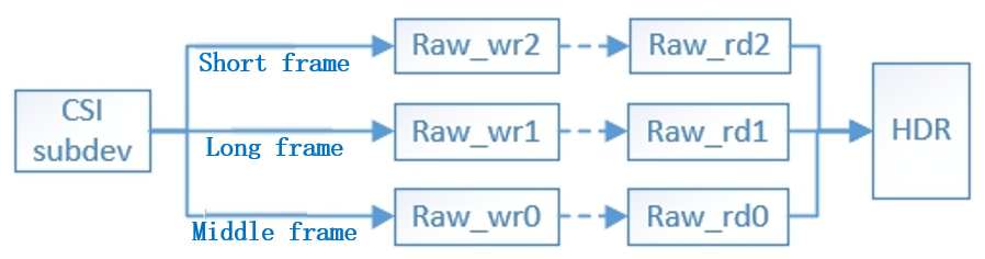
Original English figure 3, PDF page 10
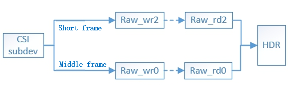
Original English figure 4, PDF page 10
The CSI subdev obtains the output information of the sensor driver in multiple pad formats through get_fmt, which corresponds to the source pad of the CSI.
Please refer to the specific configuration of MIPI sensor driver Driver migration steps
| Name | Name | Description |
|---|---|---|
| rkisp-isp- subdev |
Sensor pad0 |
ISP capture Sensor vc0 (default) wide and high format output, commonly used linear mode |
| rkisp_rawwr0 | Sensor pad1 |
Rawwr0 capture sensor vcX wide and high format output |
| rkisp_rawwr1 | Sensor pad2 |
Rawwr1 capture sensor vcX wide and high format output |
| rkisp_rawwr2 | Sensor pad3 |
Rawwr2 capture sensor vcX wide and high format output |
| rkisp_rawwr3 | Sensor pad4 |
Rawwr3 capture sensor vcX wide and high format output |
RKVICAP driver
Frame description
The RKVICAP driver is mainly based on the v4l2/media framework to implement hardware configuration, interrupt processing, control buffer rotation, and control the power on and off of subdevices (such as mipi dphy and sensor).
For RV1126/RV1109, VICAP has two IP cores, one of which is called VICAP FULL and the other is called VICAP LITE. VICAP FULL has three interfaces: dvp/mipi/lvds, dvp can work with mipi or lvds interface at the same time, but mipi and lvds cannot work at the same time, VICAP LITE only has lvds interface, which can work with VICAP FULL interface at the same time; VICAP FULL dvp The interface corresponds to a rkvicap_dvp node, the VICAP FULL mipi/lvds interface corresponds to a rkvicap_mipi_lvds node, and the VICAP LITE corresponds to a rkvicap_lite_mipi_lvds node. Each node can be collected independently.
For the RK356X chip, VICAP has only a single core and has two interfaces, dvp and mipi. The dvp interface corresponds to a rkvicap_dvp node, and the mipi interface corresponds to a rkvicap_mipi_lvds node (the same name as the VICAP FULL of RV1126/RV1109), and each node can be collected independently.
In order to synchronize the data collected by VICAP to the isp driver, it is necessary to link the logical sditf node generated by the VICAP driver to the virtual node device generated by the isp. The DVP interface corresponds to the rkvicap_dvp_sditf node, the mipi/lvds interface of VICAP FULL corresponds to the rkvicap_mipi_lvds_sditf node, and the VICAP LITE corresponds to rkvicap_lite_sditf.
Please refer to the specific dts link method of each interface CIS Device Registration (DTS)
The following figure describes the topology of the device driven by RKVICAP:
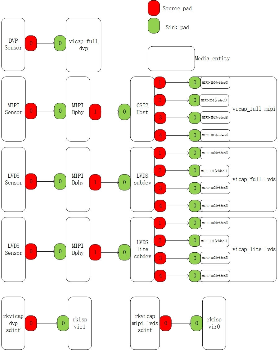
Original English figure 5, PDF page 12
Chip version different
| SOC | VI IP | VI Interface | Bayer CIS max resolution |
Feature |
|---|---|---|---|---|
| RV1109 | ISP20 ( ISP + ISPP): 1 VICAP Full: 1 VICAP Lite: 1 |
MIPI DPHY: 2 x 4Lanes 2.5Gbps/Lane LVDS: 2 x 4Lanes 1.0Gbps/Lane DVP: BT601 / BT656 / BT1120 pclk: 150MHz |
3072x2048 | Upto 3 frames HDR |
| RK3566 | ISP21 Lite: 1 VICAP Full: 1 |
MIPI DPHY: 2 x 2Lanes or 1 x 4Lanes 2.5Gbps/Lane DVP: BT601 / BT656 / BT1120 pclk: 150MHz |
4096x3072 | No HDR |
| RK3568 | ISP21:1 VICAP Full: 1 |
MIPI DPHY: 2 x 2Lanes or 1 x 4Lanes 2.5Gbps/Lane DVP: BT601 / BT656 / BT1120 pclk: 150MHz |
4096x3072 | Upto 2 frames HDR |
| RV1126 | ISP20 ( ISP + ISPP): 1 VICAP Full: 1 VICAP Lite: 1 |
MIPI DPHY: 2 x 4Lanes 2.5Gbps/Lane LVDS: 2 x 4Lanes 1.0Gbps/Lane DVP: BT601 / BT656 / BT1120 pclk: 150MHz |
4416x3312 | Upto 3 frames HDR |
CIS (cmos image sensor) driver
CIS Device Registration (DTS)
Single registration
MIPI interface
For the RV1126 and RV1106 platforms, there are two independent and complete standard physical mipi csi2 dphys, corresponding to csi_dphy0 and csi_dphy1 on dts (see RV1126.dtsi), the characteristics are as follows:
The maximum data lane is 4 lanes;
The maximum rate is 2.5Gbps/lane;
For the RK356X platform, there is only one standard physical mipi csi2 dphy, which can work in two modes: full mode and split mode, which can be split into three logical dphys (see rk3568.dtsi): csi2_dphy0/csi2_dphy1/csi2_dphy2 (see rk3568.dtsi). The features are as follows:
Full mode
Only use csi2_dphy0, csi2_dphy0 and csi2_dphy1/csi2_dphy2 are mutually exclusive and cannot be used at the same time;
The maximum data lane is 4 lanes;
The maximum rate is 2.5Gbps/lane;
Split mode
Only use csi2_dphy1 and csi2_dphy2, mutually exclusive with csi2_dphy0, and cannot be used at the same time;
csi2_dphy1 and csi2_dphy2 can be used at the same time;
The maximum data lane of csi2_dphy1 and csi2_dphy2 is 2 lanes;
csi2_dphy1 corresponds to lane0/lane1 of the physical dphy;
csi2_dphy2 corresponds to lane2/lane3 of physical dphy;
Maximum rate 2.5Gbps/lane
For specific dts use cases, see the following examples.
Link to ISP
RV1126/RV1106 platform
Take RV1126 isp and os04a10 as examples below.
Link relationship: sensor->csi_dphy->isp->ispp
arch/arm/boot/dts/RV1126-evb-v10.dtsi
Configuration points
data-lanes must specify the number of lanes used, otherwise it will not be recognized as mipi type;
  cam_ircut0: cam_ircut {
      status = "okay";
      compatible = "rockchip,ircut";
      ircut-open-gpios = <&gpio2 RK_PA7 GPIO_ACTIVE_HIGH>;
      ircut-close-gpios = <&gpio2 RK_PA6 GPIO_ACTIVE_HIGH>;
      rockchip,camera-module-index = <1>;
      rockchip,camera-module-facing = "front";
  };
  os04a10: os04a10@36 {
      // Need to be consistent with the matching string in the driver
      compatible = "ovti,os04a10";
      reg = <0x36>;// sensor I2CDevice address, 7 bits
      clocks = <&cru CLK_MIPICSI_OUT>;// sensor clickinConfiguration
      clock-names = "xvclk";
      power-domains = <&power RV1126_PD_VI>;
      pinctrl-names = "rockchip,camera_default";
      pinctrl-0 = <&mipi_csi_clk0>;// pinctl Set up
      //power supply
      avdd-supply = <&vcc_avdd>;
      dovdd-supply = <&vcc_dovdd>;
      dvdd-supply = <&vcc_dvdd>;
      // power Pin assignment and effective level
      pwdn-gpios = <&gpio1 RK_PD4 GPIO_ACTIVE_HIGH>;
      // Module number, this number should not be repeated
      rockchip,camera-module-index = <1>;
      // Module orientation which are "back" and "front"
      rockchip,camera-module-facing = "front";
      // name of moudle
      rockchip,camera-module-name = "CMK-OT1607-FV1";
      // lens name
      rockchip,camera-module-lens-name = "M12-4IR-4MP-F16";
      //ir cut device
      ir-cut = <&cam_ircut0>;
      port {
          ucam_out0: endpoint {
              // mipi dphy port
              remote-endpoint = <&mipi_in_ucam0>;
              // number of mipi lane,1lane is <1>, 4lanei s <1 2 3 4>
              data-lanes = <1 2 3 4>;
          };
      };
   };
  &csi_dphy0 {
      status = "okay";
      ports {
          #address-cells = <1>;
          #size-cells = <0>;
          port@0 {
              reg = <0>;
              #address-cells = <1>;
              #size-cells = <0>;
              mipi_in_ucam0: endpoint@1 {
                  reg = <1>;
                  // The port name of the sensor
                  remote-endpoint = <&ucam_out0>;
                  // mipi lane number,1lane is <1>, 4lane is <1 2 3 4>
                  data-lanes = <1 2 3 4>;
              };
          };
          port@1 {
              reg = <1>;
              #address-cells = <1>;
              #size-cells = <0>;
              csidphy0_out: endpoint@0 {
                  reg = <0>;
                  // name of isp port
                  remote-endpoint = <&isp_in>;
              };
          };
      };
  };
  &rkisp {
      status = "okay";
  };
  &rkisp_vir0 {
      status = "okay";
      ports {
          #address-cells = <1>;
          #size-cells = <0>;
          port@0 {
              reg = <0>;
              #address-cells = <1>;
              #size-cells = <0>;
              isp_in: endpoint@0 {
                  reg = <0>;
                  // name of mipi dphy port
                  remote-endpoint = <&csidphy0_out>;
              };
          };
          port@1 {
              reg = <1>;
              #address-cells = <1>;
              #size-cells = <0>;
              isp0_out: endpoint@1 {
                  reg = <1>;
                  // ispp port name, isp output to ispp
                  remote-endpoint = <&ispp0_in>;
              };
          };
      };
  };
  &rkispp {
      status = "okay";
  };
  &rkispp_vir0 {
      status = "okay";
      port {
          #address-cells = <1>;
          #size-cells = <0>;
          Ispp0_in: endpoint@0 {
              reg = <0>;
              // isp port name, ispp input
              remote-endpoint = <&isp0_out>;
          };
      };
  };
RK356X platform
Let’s take rk3566 isp and gc8034 4lane as examples for description:
Link relationship: sensor->csi2_dphy0->isp Configuration points
Need to configure data-lanes Need to enable csi2_dphy_hw node
      /* full mode: lane0-3 */
      gc8034: gc8034@37 {
          //Need to be consistent with the matching string in the driver
          compatible = "galaxycore,gc8034";
          status = "okay";
          // sensor I2C device address, 7 bits
          reg = <0x37>;
          // sensor mclk Source configuration
          clocks = <&cru CLK_CIF_OUT>;
          clock-names = "xvclk";
          //sensor Related power domain enable
          power-domains = <&power RK3568_PD_VI>;
          //sensor mclk pinctl set up
          pinctrl-names = "default";
          pinctrl-0 = <&cif_clk>;
          // resetPin assignment and effective level
          reset-gpios = <&gpio3 RK_PA6 GPIO_ACTIVE_LOW>;
          // powerdownPin assignment and effective level
          pwdn-gpios = <&gpio4 RK_PB2 GPIO_ACTIVE_LOW>;
          // Module number, this number should not be repeated
          rockchip,camera-module-index = <0>;
          // Module orientation, there are "back" and "front"
          rockchip,camera-module-facing = "back";
          // moudle name
          rockchip,camera-module-name = "RK-CMK-8M-2-v1";
          // lens name
          rockchip,camera-module-lens-name = "CK8401";
          port {
              gc8034_out: endpoint {
                  // csi2 dphy port name
                  remote-endpoint = <&dphy0_in>;
                  // csi2 dphy lane number,1lane is <1>, 4lane is <1 2 3 4>
                  data-lanes = <1 2 3 4>;
              };
          };
      };
      &csi2_dphy_hw {
         status = "okay";
      };
      &csi2_dphy0 {
          //csi2_dphy0 is not used simultaneously with csi2_dphy1/csi2_dphy2, mutually exclusive
          status = "okay";
          /*
           * dphy0 only used for full mode,
           * full mode and split mode are mutually exclusive
           */
          ports {
              #address-cells = <1>;
              #size-cells = <0>;
              port@0 {
                  reg = <0>;
                  #address-cells = <1>;
                  #size-cells = <0>;
                  dphy0_in: endpoint@1 {
                      reg = <1>;
                      // The port name of the sensor
                      remote-endpoint = <&gc8034_out>;
                      // csi2 dphy lane number
                      data-lanes = <1 2 3 4>;
                  };
              };
              port@1 {
                  reg = <1>;
                  #address-cells = <1>;
                  #size-cells = <0>;
                  dphy0_out: endpoint@1 {
                      reg = <1>;
                      // The port name of the isp
                      remote-endpoint = <&isp0_in>;
                  };
              };
          };
      };
  &rkisp {
      status = "okay";
  };
  &rkisp_mmu {
      status = "okay";
  };
  &rkisp_vir0 {
      status = "okay";
      port {
          #address-cells = <1>;
          #size-cells = <0>;
          isp0_in: endpoint@0 {
              reg = <0>;
              // The port name of csi2 dphy
              remote-endpoint = <&dphy0_out>;
          };
      };
  };
Link to VICAP
RV1126/RV1109 platform
Take mipi os04a10 4lane link vicap as an example:
Link relationship: sensor->csi dphy->mipi csi host->vicap Configuration points:
data-lanes must specify the number of lanes used, otherwise it will not be recognized as mipi type; dphy needs to be linked to the csi host node.
  os04a10: os04a10@36 {
          // Need to be consistent with the matching string in the driver
          compatible = "ovti,os04a10";
          // sensor I2C device address, 7 bits
          reg = <0x36>;
          // sensor mclkSource configuration
          clocks = <&cru CLK_MIPICSI_OUT>;
          clock-names = "xvclk";
          //sensor Related power domain enable
          power-domains = <&power RV1126_PD_VI>;
          avdd-supply = <&vcc_avdd>;
          dovdd-supply = <&vcc_dovdd>;
          dvdd-supply = <&vcc_dvdd>;
          //sensor mclk pinctlset up
          pinctrl-names = "rockchip,camera_default";
          pinctrl-0 = <&mipicsi_clk0>;
          // powerdownPin assignment and effective level
          pwdn-gpios = <&gpio1 RK_PD4 GPIO_ACTIVE_HIGH>;
          // Module number, this number should not be repeated
          rockchip,camera-module-index = <1>;
          // Module orientation, there are "back" and "front"
          rockchip,camera-module-facing = "front";
          // module name
          rockchip,camera-module-name = "CMK-OT1607-FV1";
          // lens name
          rockchip,camera-module-lens-name = "M12-40IRC-4MP-F16";
          // ircut name
          ir-cut = <&cam_ircut0>;
          port {
              ucam_out0: endpoint {
                  // csi2 dphy port name
                  remote-endpoint = <&mipi_in_ucam0>;
                  // csi2 dphy lane number,1lane is <1>, 4lane is  <1 2 3 4>
                  data-lanes = <1 2 3 4>;
              };
          };
      };
  &csi_dphy0 {
      //csi2_dphy0 is not simultaneous use with csi2_dphy1/csi2_dphy2 , mutually exclusive
      status = "okay";
      ports {
          #address-cells = <1>;
          #size-cells = <0>;
          port@0 {
              reg = <0>;
              #address-cells = <1>;
              #size-cells = <0>;
              mipi_in_ucam0: endpoint@1 {
                  reg = <1>;
                  // The port name of the sensor
                  remote-endpoint = <&ucam_out0>;
                  // csi2 dphy lane number
                  data-lanes = <1 2 3 4>;
              };
          };
          port@1 {
              reg = <1>;
              #address-cells = <1>;
              #size-cells = <0>;
              csidphy0_out: endpoint@0 {
                  reg = <0>;
                  // csi2 host port name
                  remote-endpoint = <&mipi_csi2_input>;
              };
          };
      };
  };
  &mipi_csi2 {
      status = "okay";
      ports {
          #address-cells = <1>;
          #size-cells = <0>;
          port@0 {
              reg = <0>;
              #address-cells = <1>;
              #size-cells = <0>;
              mipi_csi2_input: endpoint@1 {
                  reg = <1>;
                  // csi2 dphy port name
                  remote-endpoint = <&csidphy0_out>;
                  // csi2 host lane number
                  data-lanes = <1 2 3 4>;
              };
          };
          port@1 {
              reg = <1>;
              #address-cells = <1>;
              #size-cells = <0>;
              mipi_csi2_output: endpoint@0 {
                  reg = <0>;
                  // Port name on the vicap side
                  remote-endpoint = <&cif_mipi_in>;
                  // csi2 host lane number
                  data-lanes = <1 2 3 4>;
              };
          };
      };
  };
  &rkcif_mipi_lvds {
      status = "okay";
      port {
          /* MIPI CSI-2 endpoint */
          cif_mipi_in: endpoint {
              // csi2 hostport name
              remote-endpoint = <&mipi_csi2_output>;
              // vicap lane number
              data-lanes = <1 2 3 4>;
          };
      };
  };
  &rkcif_mipi_lvds_sditf {
      status = "okay";
      port {
          /* sditf endpoint */
          mipi_lvds_sditf: endpoint {
              //isp Virtual device port name
              remote-endpoint = <&isp_in>;
              //mipi csi2 dphy lane number, consistent with sensor
              data-lanes = <1 2 3 4>;
          };
      };
  };
  &rkisp {
      status = "okay";
  };
  &rkisp_vir0 {
      status = "okay";
      ports {
          port@0 {
              reg = <0>;
              #address-cells = <1>;
              #size-cells = <0>;
              isp_in: endpoint@0 {
                  reg = <0>;
                  //Endpoint name of vicap sditf
                  remote-endpoint = <&mipi_lvds_sditf>;
              };
          };
      };
  };
RK356X platform
Take gc5025 2lane linking lane2/lane3 of rk3566 evb2 mipi csi2 dphy as an example:
Link relationship: sensor->csi2 dphy->mipi csi host->vicap Configuration points
data-lanes must specify the number of lanes used, otherwise it will not be recognized as mipi type; dphy needs to be linked to the csi host node; Need to enable csi2 dphy hw node.
  /* split mode: lane:2/3 */
  gc5025: gc5025@37 {
          status = "okay";
          // Need to be consistent with the matching string in the driver
          compatible = "galaxycore,gc5025";
          // sensor I2C device address, 7 bits
          reg = <0x37>;
          // sensor mclkSource configuration
          clocks = <&pmucru CLK_WIFI>;
          clock-names = "xvclk";
          //sensor mclk pinctlset up
          pinctrl-names = "default";
          pinctrl-0 = <&refclk_pins>;
          // resetPin assignment and effective level
          reset-gpios = <&gpio3 RK_PA5 GPIO_ACTIVE_LOW>;
          // powerdownPin assignment and effective level
          pwdn-gpios = <&gpio3 RK_PB0 GPIO_ACTIVE_LOW>;
          //sensor Related power domain enable
          power-domains = <&power RK3568_PD_VI>;
          /*power-gpios = <&gpio0 RK_PC1 GPIO_ACTIVE_HIGH>;*/
          // Module number, this number should not be repeated
          rockchip,camera-module-index = <1>;
          // Module orientation, there are "back" and "front"
          rockchip,camera-module-facing = "front";
          // module name
          rockchip,camera-module-name = "TongJu";
          // lens name
          rockchip,camera-module-lens-name = "CHT842-MD";
          port {
              gc5025_out: endpoint {
                  // csi2 dphy port name
                  remote-endpoint = <&dphy2_in>;
                  // csi2 dphy lane name,2lane is <1 2>, 4lane is <1 2 3 4>
                  data-lanes = <1 2>;
              };
          };
  };
   &csi2_dphy_hw {
          status = "okay";
   };
  &csi2_dphy2 {
      //csi2_dphy0 is not used simultaneously with csi2_dphy1/csi2_dphy2, mutually
  exclusivee;can be used in parallel with csi2_dphy1
      status = "okay";
      /*
       * dphy2 only used for split mode,
       * can be used  concurrently  with dphy1
       * full mode and split mode are mutually exclusive
       */
      ports {
          #address-cells = <1>;
          #size-cells = <0>;
          port@0 {
              reg = <0>;
              #address-cells = <1>;
              #size-cells = <0>;
              dphy2_in: endpoint@1 {
                  reg = <1>;
                  // The port name of the sensor
                  remote-endpoint = <&gc5025_out>;
                  // csi2 dphy lane name
                  data-lanes = <1 2>;
              };
          };
          port@1 {
              reg = <1>;
              #address-cells = <1>;
              #size-cells = <0>;
              dphy2_out: endpoint@1 {
                  reg = <1>;
                  // csi2 host port name
                  remote-endpoint = <&mipi_csi2_input>;
              };
          };
      };
  };
  &mipi_csi2 {
      status = "okay";
      ports {
          #address-cells = <1>;
          #size-cells = <0>;
          port@0 {
              reg = <0>;
              #address-cells = <1>;
              #size-cells = <0>;
              mipi_csi2_input: endpoint@1 {
                  reg = <1>;
                  // csi2 dphy port name
                  remote-endpoint = <&dphy2_out>;
                  // csi2 host lane number
                  data-lanes = <1 2>;
              };
          };
          port@1 {
              reg = <1>;
              #address-cells = <1>;
              #size-cells = <0>;
              mipi_csi2_output: endpoint@0 {
                  reg = <0>;
                  // vicapport name
                  remote-endpoint = <&cif_mipi_in>;
                  // csi2 host lane number
                  data-lanes = <1 2>;
              };
          };
      };
  };
  &rkcif_mipi_lvds {
      status = "okay";
      port {
          cif_mipi_in: endpoint {
              // csi2 hostport name
              remote-endpoint = <&mipi_csi2_output>;
              // vicap lane number
              data-lanes = <1 2>;
          };
      };
  };
  &rkcif_mipi_lvds_sditf {
      status = "okay";
      port {
          /* MIPI CSI-2 endpoint */
          mipi_lvds_sditf: endpoint {
              //isp Virtual device port name
              remote-endpoint = <&isp_in>;
              //mipi csi2 dphy lane number,consistent with sensor
              data-lanes = <1 2>;
          };
      };
  };
  &rkisp {
      status = "okay";
  };
  &rkisp_vir0 {
      status = "okay";
      ports {
          port@0 {
              reg = <0>;
              #address-cells = <1>;
              #size-cells = <0>;
              isp_in: endpoint@0 {
                  reg = <0>;
                  //vicap mipi sditf port name
                  remote-endpoint = <&mipi_lvds_sditf>;
              };
          };
      };
  };
LVDS interface
Link to VICAP
RV1126/RV1109 platform
Take imx327 4lane as an example, the link relationship is as follows:
Link relationship: sensor->csi dphy->vicap Configuration points
dphy does not need to link to the CSI host node, otherwise it will cause no data to be received; data-lanes must specify the specific number of lanes used, otherwise it will cause no data to be received; The bus-type must be configured to 3, otherwise it will not be recognized as an LVDS interface, resulting in link establishment failure;
  imx327: imx327@1a {
          // Need to be consistent with the matching string in the driver
          compatible = "sony,imx327";
          // sensor I2C device address, 7 bits
          reg = <0x1a>;
          // sensor mclkSource configuration
          clocks = <&cru CLK_MIPICSI_OUT>;
          clock-names = "xvclk";
          //sensor Related power domain enable
          power-domains = <&power RV1126_PD_VI>;
          avdd-supply = <&vcc_avdd>;
          dovdd-supply = <&vcc_dovdd>;
          dvdd-supply = <&vcc_dvdd>;
          //sensor mclk pinctlset up
          pinctrl-names = "default";
          pinctrl-0 = <&mipicsi_clk0>;
          // powerdownPin assignment and effective level
          pwdn-gpios = <&gpio3 RK_PA6 GPIO_ACTIVE_HIGH>;
          // resetPin assignment and effective level
          reset-gpios = <&gpio1 RK_PD5 GPIO_ACTIVE_HIGH>;
          // Module number, this number should not be repeated
          rockchip,camera-module-index = <1>;
          // Module orientation, there are "back" and "front"
          rockchip,camera-module-facing = "front";
          // module name
          rockchip,camera-module-name = "CMK-OT1607-FV1";
          // lens name
          rockchip,camera-module-lens-name = "M12-4IR-4MP-F16";
          // ircut name
          ir-cut = <&cam_ircut0>;
          port {
              ucam_out0: endpoint {
                  // csi2 dphy port name
                  remote-endpoint = <&mipi_in_ucam0>;
                  // lvds lane number,1lane is <1>, 4lane is <4>,must be specified
                  data-lanes = <4>;
                  // Type of lvds interface, must be specified
                  bus-type = <3>;
              };
          };
  };
  &csi_dphy0 {
      //csi2_dphy0 is not simultaneous use with csi2_dphy1/csi2_dphy2, mutually exclusive
      status = "okay";
      ports {
          #address-cells = <1>;
          #size-cells = <0>;
          port@0 {
              reg = <0>;
              #address-cells = <1>;
              #size-cells = <0>;
              mipi_in_ucam0: endpoint@1 {
                  reg = <1>;
                  // The port name of the sensor
                  remote-endpoint = <&ucam_out0>;
                  // lvds lane number,1lane is <1>, 4lane is <4>,must be specified
                  data-lanes = <4>;
                  // Type of lvds interface, must be specified
                  bus-type = <3>;
              };
          };
          port@1 {
              reg = <1>;
              #address-cells = <1>;
              #size-cells = <0>;
              csidphy0_out: endpoint@0 {
                  reg = <0>;
                  // vicap liteport name
                  remote-endpoint = <&cif_lite_lvds_in>;
                  // lvds lane number,1lane is <1>, 4lane is <4>,must be specified
                  data-lanes = <4>;
                  // Type of lvds interface, must be specified
                  bus-type = <3>;
              };
          };
      };
  };
  &rkcif_lite_mipi_lvds {
      status = "okay";
      port {
          /* lvds endpoint */
          cif_lite_lvds_in: endpoint {
              // csi2 dphy port name
              remote-endpoint = <&csidphy0_out>;
              //csi2 dphy lvds lane name,1lane is <1>, 4lane is <4>,must be specified
              data-lanes = <4>;
              //Type of lvds interface, must be specified
              bus-type = <3>;
          };
      };
  };
  &rkcif_lite_sditf {
      status = "okay";
      port {
          /* lvds endpoint */
          lite_sditf: endpoint {
              //isp Virtual device port name
              remote-endpoint = <&isp_in>;
              //csi2 dphy lane number, consistent with sensor
              data-lanes = <4>;
          };
      };
  };
  &rkisp {
      status = "okay";
  };
  &rkisp_vir0 {
      status = "okay";
      ports {
          port@0 {
              reg = <0>;
              #address-cells = <1>;
              #size-cells = <0>;
              isp_in: endpoint@0 {
                  reg = <0>;
                  //lite vicap lvds sditf port name
                  remote-endpoint = <&lite_sditf>;
              };
          };
      };
  };
DVP interface Link to VICAP
On the RV1126/RV1106/RK356X platform, the dts configuration of each related interface of DVP is the same.
BT601
Take ar0230 BT601 as an example, the link relationship is as follows:
Link relationship: sensor->vicap Configuration points
hsync-active/vsync-active must be configured for asynchronous registration of the v4l2 framework to identify the BT601 interface, if not configured, it will be identified as the BT656 interface; pclk-sample/bus-width is optional; In the g_mbus_config interface of the sensor driver, the valid polarity of the hsync- acitve/vsync-active/pclk-ative of the current sensor must be indicated by the flag, otherwise the data will not be received; pinctrl needs to be quoted in order to do corresponding iomux for BT601 related gpio, otherwise it will lead to failure to receive data;
The sample code of the g_mbus_config interface is as follows:
  static int ar0230_g_mbus_config(struct v4l2_subdev *sd,
                  struct v4l2_mbus_config *config)
  {
      config->type = V4L2_MBUS_PARALLEL;
      config->flags = V4L2_MBUS_HSYNC_ACTIVE_HIGH |
              V4L2_MBUS_VSYNC_ACTIVE_HIGH |
              V4L2_MBUS_PCLK_SAMPLE_FALLING;
      return 0;
  }
The DTS configuration example is as follows:
  ar0230: ar0230@10 {
          // Need to be consistent with the matching string in the driver
          compatible = "aptina,ar0230";
          // sensor I2C device address, 7 bits
          reg = <0x10>;
          // sensor mclkSource configuration
          clocks = <&cru CLK_CIF_OUT>;
          clock-names = "xvclk";
          //sensor Related power domain enable
          avdd-supply = <&vcc_avdd>;
          dovdd-supply = <&vcc_dovdd>;
          dvdd-supply = <&vcc_dvdd>;
          power-domains = <&power RV1126_PD_VI>;
          // powerdownPin assignment and effective level
          pwdn-gpios = <&gpio2 RK_PA6 GPIO_ACTIVE_HIGH>;
          /*reset-gpios = <&gpio2 RK_PC5 GPIO_ACTIVE_HIGH>;*/
          //Configure dvp related data pins and clock pins
          pinctrl-names = "default";
          pinctrl-0 = <&cifm0_dvp_ctl>;
          // Module number, this number should not be repeated
          rockchip,camera-module-index = <0>;
          // Module orientation, there are "back" and "front"
          rockchip,camera-module-facing = "back";
          // module name
          rockchip,camera-module-name = "CMK-OT0836-PT2";
          // lens name
          rockchip,camera-module-lens-name = "YT-2929";
          port {
              cam_para_out1: endpoint {
                  remote-endpoint = <&cif_para_in>;
              };
          };
  };
  &rkcif_dvp {
      status = "okay";
      port {
          /* Parallel bus endpoint */
          cif_para_in: endpoint {
              //sensor port endpoint name
              remote-endpoint = <&cam_para_out1>;
              //Sensor configuration parameters
              bus-width = <12>;
              hsync-active = <1>;
              vsync-active = <1>;
              pclk-sample = <0>;
          };
      };
  };
  &rkcif_dvp_sditf {
      status = "okay";
      port {
          /* parallel endpoint */
          dvp_sditf: endpoint {
              //isp Virtual device port name
              remote-endpoint = <&isp_in>;
              //Sensor configuration parameters
              bus-width = <12>;
              hsync-active = <1>;
              vsync-active = <1>;
              pclk-sample = <0>;
          };
      };
  };
  &rkisp {
      status = "okay";
  };
  &rkisp_vir0 {
      status = "okay";
      ports {
          port@0 {
              reg = <0>;
              #address-cells = <1>;
              #size-cells = <0>;
              isp_in: endpoint@0 {
                  reg = <0>;
                  //dvp sditf port name
                  remote-endpoint = <&dvp_sditf>;
              };
          };
      };
  };
BT656/BT1120
The dts usage of BT656/BT1120 is the same.
Take ava fpga bt1120 as an example, the link relationship is as follows:
Link relationship: sensor->vicap Configuration points
Do not configure hsync-active/vsync-active, otherwise the v4l2 framework will recognize it as BT601 during asynchronous registration;
pclk-sample/bus-width is optional;
In the g_mbus_config interface of the sensor driver, the valid polarity of the pclk-ative of the current sensor must be indicated by the flag, otherwise the data will not be received;
The querystd interface in v4l2_subdev_video_ops must be implemented, indicating that the current interface is an ATSC interface, otherwise the data will not be received;
pinctrl needs to be quoted in order to do corresponding iomux for bt656/bt1120 related gpio, otherwise it will result in failure to receive data.
The sample code of the g_mbus_config interface is as follows:
  static int avafpga_g_mbus_config(struct v4l2_subdev *sd,
                  struct v4l2_mbus_config *config)
  {
      config->type = V4L2_MBUS_BT656;
      config->flags = V4L2_MBUS_PCLK_SAMPLE_RISING;
      return 0;
  }
An example of the querystd interface is as follows:
  static int avafpga_querystd(struct v4l2_subdev *sd, v4l2_std_id *std)
  {
      *std = V4L2_STD_ATSC;
      return 0;
  }
The dts configuration example is as follows:
  avafpga: avafpga@70 {
      // Need to be consistent with the matching string in the driver
      compatible = "ava,fpga";
      // sensor I2C device address, 7 bits
      reg = <0x10>;
      // sensor mclkSource configuration
      clocks = <&cru CLK_CIF_OUT>;
      clock-names = "xvclk";
      //sensor Related power domain enable
      avdd-supply = <&vcc_avdd>;
      dovdd-supply = <&vcc_dovdd>;
      dvdd-supply = <&vcc_dvdd>;
      // powerdownPin assignment and effective level
      power-domains = <&power RV1126_PD_VI>;
      pwdn-gpios = <&gpio2 RK_PA6 GPIO_ACTIVE_HIGH>;
      /*reset-gpios = <&gpio2 RK_PC5 GPIO_ACTIVE_HIGH>;*/
      //Configure dvp related data pins and clock pins
      pinctrl-names = "default";
      pinctrl-0 = <&cifm0_dvp_ctl>;
      // Module number, this number should not be repeated
      rockchip,camera-module-index = <0>;
      // Module orientation, there are "back" and "front"
      rockchip,camera-module-facing = "back";
      // module name
      rockchip,camera-module-name = "CMK-OT0836-PT2";
      // lens name
      rockchip,camera-module-lens-name = "YT-2929";
      port {
          cam_para_out2: endpoint {
              remote-endpoint = <&cif_para_in>;
          };
      };
  };
  &rkcif_dvp {
      status = "okay";
      port {
          /* Parallel bus endpoint */
          cif_para_in: endpoint {
              //sensor port endpoint name
              remote-endpoint = <&cam_para_out2>;
              //Sensor configuration parameters,Optional
              bus-width = <16>;
              pclk-sample = <1>;
          };
      };
  };
  &rkcif_dvp_sditf {
      status = "okay";
      port {
          /* parallel endpoint */
          dvp_sditf: endpoint {
              //isp Virtual device port name
              remote-endpoint = <&isp_in>;
              bus-width = <16>;
              pclk-sample = <1>;
          };
      };
  };
  &rkisp {
      status = "okay";
  };
  &rkisp_vir0 {
      status = "okay";
      ports {
          port@0 {
              reg = <0>;
              #address-cells = <1>;
              #size-cells = <0>;
              isp_in: endpoint@0 {
                  reg = <0>;
                  //dvp sditf port name
                  remote-endpoint = <&dvp_sditf>;
              };
          };
      };
  };
Multi-sensor registration
A single hardware isp virtualizes multiple devices and processes multiple raw sensor data in time division multiplexing.
On the RV1126/RV1106 platform Link relationship, isp0->ispp0 and isp1->ispp1 are fixed configuration RV1126.dtsi Mipi into isp or cif into isp is optional.
E.g:
sensor0->csi_dphy0->csi2->vicap->isp0->ispp0 sensor1->csi_dphy1->isp1->ispp1
Example reference arch/arm/boot/dts/RV1109-evb-ddr3-v12-facial-gate.dts gc2053->csi_dphy0->csi2->cif->isp1->ispp1 ov2718->csi_dphy1->isp0->ispp0 The following configuration is very important for different resolutions
&rkispp { status = "okay"; /* the max input w h and fps of mulit sensor */ max-input = <2688 1520 30>;//Take the maximum width and height and frame rate of different sensors };
On the RK3566/RK3568 platform
E.g:
ov5695->dphy1->isp_vir0
gc5025->dphy2->csi2->vicap->isp_vir1
  ov5695: ov5695@36 {
          status = "okay";
          ...
          port {
              ov5695_out: endpoint {
                  remote-endpoint = <&dphy1_in>;
                  data-lanes = <1 2>;
              };
          };
  };
  gc5025: gc5025@37 {
          status = "okay";
          ...
          port {
              gc5025_out: endpoint {
                  remote-endpoint = <&dphy2_in>;
                  data-lanes = <1 2>;
              };
          };
  };
   &csi2_dphy_hw {
          status = "okay";
   };
  &csi2_dphy1 {
      status = "okay";
      ports {
          #address-cells = <1>;
          #size-cells = <0>;
          port@0 {
              reg = <0>;
              #address-cells = <1>;
              #size-cells = <0>;
              dphy1_in: endpoint@1 {
                  reg = <1>;
                  remote-endpoint = <&ov5695_out>;
                  data-lanes = <1 2>;
              };
          };
          port@1 {
              reg = <1>;
              #address-cells = <1>;
              #size-cells = <0>;
              dphy1_out: endpoint@1 {
                  reg = <1>;
                  remote-endpoint = <&isp0_in>;
              };
          };
      };
  };
  &csi2_dphy2 {
      status = "okay";
      ports {
          #address-cells = <1>;
          #size-cells = <0>;
          port@0 {
              reg = <0>;
              #address-cells = <1>;
              #size-cells = <0>;
              dphy2_in: endpoint@1 {
                  reg = <1>;
                  remote-endpoint = <&gc5025_out>;
                  data-lanes = <1 2>;
              };
          };
          port@1 {
              reg = <1>;
              #address-cells = <1>;
              #size-cells = <0>;
              dphy2_out: endpoint@1 {
                  reg = <1>;
                  remote-endpoint = <&mipi_csi2_input>;
              };
          };
      };
  };
  &mipi_csi2 {
      status = "okay";
      ports {
          #address-cells = <1>;
          #size-cells = <0>;
          port@0 {
              reg = <0>;
              #address-cells = <1>;
              #size-cells = <0>;
              mipi_csi2_input: endpoint@1 {
                  reg = <1>;
                  remote-endpoint = <&dphy2_out>;
                  data-lanes = <1 2>;
              };
          };
          port@1 {
              reg = <1>;
              #address-cells = <1>;
              #size-cells = <0>;
              mipi_csi2_output: endpoint@0 {
                  reg = <0>;
                  remote-endpoint = <&cif_mipi_in>;
                  data-lanes = <1 2>;
              };
          };
      };
  };
  &rkcif_mipi_lvds {
      status = "okay";
      port {
          cif_mipi_in: endpoint {
              remote-endpoint = <&mipi_csi2_output>;
              data-lanes = <1 2>;
          };
      };
  };
  &rkcif_mipi_lvds_sditf {
      status = "okay";
      port {
          mipi_lvds_sditf: endpoint {
              remote-endpoint = <&isp1_in>;
              data-lanes = <1 2>;
          };
      };
  };
  &rkisp {
      status = "okay";
      /* the max input w h and fps of mulit sensor */
      max-input = <2592 1944 30>;
  };
  &rkisp_vir0 {
      status = "okay";
      ports {
          port@0 {
              reg = <0>;
              #address-cells = <1>;
              #size-cells = <0>;
              isp0_in: endpoint@0 {
                  reg = <0>;
                  remote-endpoint = <&dphy1_out>;
              };
          };
      };
  };
  &rkisp_vir1 {
      status = "okay";
      ports {
          port@0 {
              reg = <0>;
              #address-cells = <1>;
              #size-cells = <0>;
              isp1_in: endpoint@0 {
                  reg = <0>;
                  remote-endpoint = <&mipi_lvds_sditf>;
              };
          };
      };
  };
CIS driver description
Camera Sensor uses I2C to interact with the host. The sensor driver is currently implemented in accordance with the I2C device driver. The sensor driver also uses the v4l2 subdev method to interact with the host driver.
Brief description of data type
struct i2c_driver
[Description]
Define i2c device driver information
[Definition]
  struct i2c_driver {
      ……
      /* Standard driver model interfaces */
      int (*probe)(struct i2c_client *, const struct i2c_device_id *);
      int (*remove)(struct i2c_client *);
      ……
      struct device_driver driver;
      const struct i2c_device_id *id_table;
      ……
  };
[Key Member]
| Member name |
Description |
|---|---|
| @driver | Device driver model driver mainly contains the name of the driver and the of_match_table that matches the DTS registered device. When the compatible field in of_match_table matches the compatible field in the dts file, the .probe function will be called |
| @id_table | List of I2C devices supported by this driver If the kernel does not use of_match_table and dts registered devices for matching, the kernel uses this table for matching |
| @probe | Callback for device binding |
| @remove | Callback for device unbinding |
[Example]
  #if IS_ENABLED(CONFIG_OF)
  static const struct of_device_id os04a10_of_match[] = {
      { .compatible = "ovti,os04a10" },
      {},
  };
  MODULE_DEVICE_TABLE(of, os04a10_of_match);
  #endif
  static const struct i2c_device_id os04a10_match_id[] = {
      { "ovti,os04a10", 0 },
      { },
  };
  static struct i2c_driver os04a10_i2c_driver = {
      .driver = {
          .name = OS04A10_NAME,
          .pm = &os04a10_pm_ops,
          .of_match_table = of_match_ptr(os04a10_of_match),
      },
      .probe      = &os04a10_probe,
      .remove     = &os04a10_remove,
      .id_table   = os04a10_match_id,
  };
  static int __init sensor_mod_init(void)
  {
      return i2c_add_driver(&os04a10_i2c_driver);
  }
  static void __exit sensor_mod_exit(void)
  {
      i2c_del_driver(&os04a10_i2c_driver);
  }
  device_initcall_sync(sensor_mod_init);
  module_exit(sensor_mod_exit);
struct v4l2_subdev_ops
[Description]
Define ops callbacks for subdevs.
[definition]
  struct v4l2_subdev_ops {
      const struct v4l2_subdev_core_ops   *core;
      ……
      const struct v4l2_subdev_video_ops  *video;
      ……
      const struct v4l2_subdev_pad_ops    *pad;
  };
[Key Member]
| Member name | Description |
|---|---|
| .core | Define core ops callbacks for subdevs |
| .video | Callbacks used when v4l device was opened in video mode. |
| .pad | v4l2-subdev pad level operations |
[Example]
  static const struct v4l2_subdev_ops os04a10_subdev_ops = {
      .core   = &os04a10_core_ops,
      .video  = &os04a10_video_ops,
      .pad    = &os04a10_pad_ops,
  };
struct v4l2_subdev_core_ops
[Description]
Define core ops callbacks for subdevs.
[Definition]
  struct v4l2_subdev_core_ops {
      ……
      int (*s_power)(struct v4l2_subdev *sd, int on);
      long (*ioctl)(struct v4l2_subdev *sd, unsigned int cmd, void *arg);
  #ifdef CONFIG_COMPAT
      long (*compat_ioctl32)(struct v4l2_subdev *sd, unsigned int cmd,
          unsigned long arg);
  #endif
      ……
  };
[Key Member]
| Member name | Description |
|---|---|
| .s_power | puts subdevice in power saving mode (on == 0) or normal operation mode (on == 1). |
| .ioctl | called at the end of ioctl() syscall handler at the V4L2 core.used to provide support for private ioctls used on the driver. |
| .compat_ioctl32 | called when a 32 bits application uses a 64 bits Kernel, in order to fix data passed from/to userspace.in order to fix data passed from/to userspace. |
[Example]
  static const struct v4l2_subdev_core_ops os04a10_core_ops = {
      .s_power = os04a10_s_power,
      .ioctl = os04a10_ioctl,
  #ifdef CONFIG_COMPAT
      .compat_ioctl32 = os04a10_compat_ioctl32,
  #endif
  };
At present, the following private ioctl is used to realize the query of module information and the query setting of OTP information
| Private ioctl | description |
|---|---|
| RKMODULE_GET_MODULE_INFO | Get module information, refer to struct rkmodule_inf; |
| RKMODULE_AWB_CFG | Switch sensor’s compensation function for AWB; if the module does not burn the golden AWB value, you can set it here; for details, please refer to struct rkmodule awb_cfg; |
| RKMODULE_LSC_CFG | Switch sensor’s compensation function for LSC; refer to struct rkmodule_lsc_cfg; |
| PREISP_CMD_SET_HDRAE_EXP | HDR exposure setting detailed reference struct preisp_hdrae_exp_s |
| RKMODULE_SET_HDR_CFG | Set the HDR mode to switch between normal and HDR modes. Need to drive to adapt to normal and HDR 2 groups of configuration information, please refer to struct rkmodule_hdr_cfg for details |
| RKMODULE_GET_HDR_CFG | To get the current HDR mode, please refer to struct rkmodule_hdr_cfg for details |
| RKMODULE_SET_CONVERSION_GAIN | Set the conversion gain of linear mode, such as imx347, os04a10 sensor with conversion gain function, if the sensor does not support conversion gain, it may not be implemented |
struct v4l2_subdev_video_ops
[Description]
Callbacks used when v4l device was opened in video mode.
[Definition]
  struct v4l2_subdev_video_ops {
      ……
      int (*s_stream)(struct v4l2_subdev *sd, int enable);
      ……
      int (*g_frame_interval)(struct v4l2_subdev *sd,
                  struct v4l2_subdev_frame_interval *interval);
      int (*g_mbus_config)(struct v4l2_subdev *sd,
                 struct v4l2_mbus_config *cfg);
   ……
  };
[Key Member]
| Member name | Description |
|---|---|
| .g_frame_interval | callback for VIDIOC_SUBDEV_G_FRAME_INTERVAL ioctl handler code |
| .s_stream | used to notify the driver that a video stream will start or has stopped |
| .g_mbus_config | get supported mediabus configurations |
[Example]
  static const struct v4l2_subdev_video_ops os04a10_video_ops = {
      .s_stream = os04a10_s_stream,
      .g_frame_interval = os04a10_g_frame_interval,
      .g_mbus_config = os04a10_g_mbus_config,
  };
struct v4l2_subdev_pad_ops
[Description]
v4l2-subdev pad level operations
[Definition]
  struct v4l2_subdev_pad_ops {
      ……
      int (*enum_mbus_code)(struct v4l2_subdev *sd,
                 struct v4l2_subdev_pad_config *cfg,
                 struct v4l2_subdev_mbus_code_enum *code);
      int (*enum_frame_size)(struct v4l2_subdev *sd,
                  struct v4l2_subdev_pad_config *cfg,
                  struct v4l2_subdev_frame_size_enum *fse);
      int (*get_fmt)(struct v4l2_subdev *sd,
                  struct v4l2_subdev_pad_config *cfg,
                  struct v4l2_subdev_format *format);
      int (*set_fmt)(struct v4l2_subdev *sd,
                  struct v4l2_subdev_pad_config *cfg,
                  struct v4l2_subdev_format *format);
      int (*enum_frame_interval)(struct v4l2_subdev *sd,
                  struct v4l2_subdev_pad_config *cfg,
                  struct v4l2_subdev_frame_interval_enum *fie);
      int (*get_selection)(struct v4l2_subdev *sd,
                  struct v4l2_subdev_pad_config *cfg,
                  struct v4l2_subdev_selection *sel);
      ……
  };
[Key Member]
| Member name | Description |
|---|---|
| . enum_mbus_code | callback for VIDIOC_SUBDEV_ENUM_MBUS_CODE ioctl handler code. |
| . enum_frame_size | callback for VIDIOC_SUBDEV_ENUM_FRAME_SIZE ioctl handler code. |
| .s_fmt | callback for VIDIOC_SUBDEV_S_FMT ioctl handler code. |
| .g_fmt | callback for VIDIOC_SUBDEV_G_FMT ioctl handler code |
| .enum_frame_interval | callback for VIDIOC_SUBDEV_ENUM_FRAME_INTERVAL() ioctl handler code. |
| .get_selection | callback for VIDIOC_SUBDEV_G_SELECTION() ioctl handler code. |
[Example]
  static const struct v4l2_subdev_pad_ops os04a10_pad_ops = {
      .enum_mbus_code = os04a10_enum_mbus_code,
      .enum_frame_size = os04a10_enum_frame_sizes,
      .enum_frame_interval = os04a10_enum_frame_interval,
      .get_fmt = os04a10_get_fmt,
      .set_fmt = os04a10_set_fmt,
  };
struct v4l2_ctrl_ops
[Description]
The control operations that the driver has to provide.
[Definition]
  struct v4l2_ctrl_ops {
      int (*s_ctrl)(struct v4l2_ctrl *ctrl);
  };
[Key Member]
| Member name | Description |
|---|---|
| .s_ctrl | actually set the new control value. |
[Example]
  static const struct v4l2_ctrl_ops os04a10_ctrl_ops = {
      .s_ctrl = os04a10_set_ctrl,
  };
The RKISP driver requires the use of user controls provided by the framework. The cameras sensor driver must implement the following control functions, refer to CIS driver V4L2-controls list 1
struct xxxx_mode
[Description]
Sensor can support the information of each mode.
This structure can often be seen in the sensor driver, although it is not required by the v4l2 standard.
[Definition]
  struct xxxx_mode {
      u32 bus_fmt;
      u32 width;
      u32 height;
      struct v4l2_fract max_fps;
      u32 hts_def;
      u32 vts_def;
      u32 exp_def;
      const struct regval *reg_list;
      u32 hdr_mode;
      u32 vc[PAD_MAX];
  };
[Key Member]
| Member name |
Description |
|---|---|
| .bus_fmt | Sensor output format, reference MEDIA_BUS_FMT table |
| .width | The effective image width, which needs to be consistent with the width output of the sensor currently configured |
| .height | The effective image height, which needs to be consistent with the height output of the sensor currently configured |
| .max_fps | Image FPS, denominator/numerator is fps |
| hts_def | Default HTS, which is the effective image width + HBLANK |
| vts_def | Default VTS, which is the effective image height + VBLANK |
| exp_def | Default exposure time |
| *reg_list | Register list |
| .hdr_mode | Sensor working mode, support linear mode, two-frame synthesis HDR, three-frame synthesis HDR |
| .vc[PAD_MAX] | Configure MIPI VC channel |
[Example]
   enum os04a10_max_pad {
      PAD0, /* link to isp */
      PAD1, /* link to csi rawwr0 | hdr x2:L x3:M */
      PAD2, /* link to csi rawwr1 | hdr    x3:L */
      PAD3, /* link to csi rawwr2 | hdr x2:M x3:S */
      PAD_MAX,
  };
  static const struct os04a10_mode supported_modes[] = {
      {
          .bus_fmt = MEDIA_BUS_FMT_SBGGR12_1X12,
          .width = 2688,
          .height = 1520,
          .max_fps = {
              .numerator = 10000,
              .denominator = 300372,
          },
          .exp_def = 0x0240,
          .hts_def = 0x05c4 * 2,
          .vts_def = 0x0984,
          .reg_list = os04a10_linear12bit_2688x1520_regs,
          .hdr_mode = NO_HDR,
          .vc[PAD0] = V4L2_MBUS_CSI2_CHANNEL_0,
      }, {
          .bus_fmt = MEDIA_BUS_FMT_SBGGR12_1X12,
          .width = 2688,
          .height = 1520,
          .max_fps = {
              .numerator = 10000,
              .denominator = 225000,
          },
          .exp_def = 0x0240,
          .hts_def = 0x05c4 * 2,
          .vts_def = 0x0658,
          .reg_list = os04a10_hdr12bit_2688x1520_regs,
          .hdr_mode = HDR_X2,
          .vc[PAD0] = V4L2_MBUS_CSI2_CHANNEL_1,
          .vc[PAD1] = V4L2_MBUS_CSI2_CHANNEL_0,//L->csi wr0
          .vc[PAD2] = V4L2_MBUS_CSI2_CHANNEL_1,
          .vc[PAD3] = V4L2_MBUS_CSI2_CHANNEL_1,//M->csi wr2
      },
  };
struct v4l2_mbus_framefmt
[Description]
frame format on the media bus
[Definition]
  struct v4l2_mbus_framefmt {
      __u32           width;
      __u32           height;
      __u32           code;
      __u32           field;
      __u32           colorspace;
      __u16           ycbcr_enc;
      __u16           quantization;
      __u16           xfer_func;
      __u16           reserved[11];
  };
[Key Member]
| Member name |
Description |
|---|---|
| width | Frame width |
| height | Frame height |
| code | Reference to MEDIA_BUS_FMT table |
| field | V4L2_FIELD_NONE: Frame output mode V4L2_FIELD_INTERLACED: Field output mode |
[Example]
struct rkmodule_base_inf
[Description]
Basic module information, the upper layer uses this information to match with IQ
[Definition]
  struct rkmodule_base_inf {
      char sensor[RKMODULE_NAME_LEN];
      char module[RKMODULE_NAME_LEN];
      char lens[RKMODULE_NAME_LEN];
  } __attribute__ ((packed));
[Key Member]
| Member name | Description |
|---|---|
| sensor | sensor name, obtained from the sensor driver |
| module | module name, obtained from DTS configuration, subject to module data |
| lens | Lens name, obtained from DTS configuration, subject to module data |
[Example]
struct rkmodule_fac_inf
[Description]
Module OTP factory information
[Definition]
  struct rkmodule_fac_inf {
      __u32 flag;
      char module[RKMODULE_NAME_LEN];
      char lens[RKMODULE_NAME_LEN];
      __u32 year;
      __u32 month;
      __u32 day;
  } __attribute__ ((packed));
[Key Member]
| Member name |
Description |
|---|---|
| flag | Whether the group information is valid or not |
| module | module name, get the number from OTP, get the module name from the number |
| lens | Lens name, get the number from OTP, get the lens name from the number |
| year | Year of production, such as 12 for 2012 |
| month | Production month |
| day | Production date |
[Example]
struct rkmodule_awb_inf
[Description]
Module OTP awb measurement information
[Definition]
  struct rkmodule_awb_inf {
      __u32 flag;
      __u32 r_value;
      __u32 b_value;
      __u32 gr_value;
      __u32 gb_value;
      __u32 golden_r_value;
      __u32 golden_b_value;
      __u32 golden_gr_value;
      __u32 golden_gb_value;
  } __attribute__ ((packed));
[Key Member]
| Member name | Description |
|---|---|
| flag | Whether the group information is valid or not |
| r_value | AWB R measurement information of the current module |
| b_value | AWB B measurement information of the current module |
| gr_value | AWB GR measurement information of the current module |
| gb_value | AWB GB measurement information of the current module |
| golden_r_value | AWB R measurement information of a typical module, if not programmed, set to 0 |
| golden_b_value | AWB B measurement information of a typical module, if not programmed, set to 0 |
| golden_gr_value | AWB GR measurement information of a typical module, if not programmed, set to 0 |
| golden_gb_value | AWB GB measurement information of a typical module, if not programmed, set to 0 |
[Example]
struct rkmodule_lsc_inf
[Description]
Module OTP lsc measurement information
[Definition]
  struct rkmodule_lsc_inf {
      __u32 flag;
      __u16 lsc_w;
      __u16 lsc_h;
      __u16 decimal_bits;
      __u16 lsc_r[RKMODULE_LSCDATA_LEN];
      __u16 lsc_b[RKMODULE_LSCDATA_LEN];
      __u16 lsc_gr[RKMODULE_LSCDATA_LEN];
      __u16 lsc_gb[RKMODULE_LSCDATA_LEN];
  } __attribute__ ((packed));
[Key Member]
| Member name |
Description |
|---|---|
| flag | Whether the group information is valid or not |
| lsc_w | The actual width of the lsc table |
| lsc_h | lsc table actual height |
| decimal_bits | The number of decimal places of the lsc measurement information, if it is not available, set it to 0 |
| lsc_r | lsc r measurement information |
| lsc_b | lsc b measurement information |
| lsc_gr | lsc gr measurement information |
| lsc_gb | lsc gb measurement information |
[Example]
struct rkmodule_af_inf
[Description]
Module OTP af measurement information
[Definition]
  struct rkmodule_af_inf {
      __u32 flag; // Whether this group of information is a valid flag
      __u32 vcm_start; // vcm start current
      __u32 vcm_end; // vcm termination current
      __u32 vcm_dir; // vcm measurement direction
  } __attribute__ ((packed));
[Key Member]
| Member name | Description |
|---|---|
| flag | Whether the group information is valid or not |
| vcm_start | vcm start current |
| vcm_end | vcm end current |
| vcm_dir | vcm determination direction |
[Example]
struct rkmodule_inf
[Description]
Module information
[Definition]
  struct rkmodule_inf {
      struct rkmodule_base_inf base;
      struct rkmodule_fac_inf fac;
      struct rkmodule_awb_inf awb;
      struct rkmodule_lsc_inf lsc;
      struct rkmodule_af_inf af;
  } __attribute__ ((packed));
[Key Member]
| Member name | Description |
|---|---|
| base | Module basic information |
| fac | Module OTP Factory Information |
| awb | Module OTP awb measurement information |
| lsc | Module OTP lsc measurement information |
| af | Module OTP af measurement information |
[Example]
struct rkmodule_awb_cfg
[Description]
Module OTP awb configuration information
[Definition]
  struct rkmodule_awb_cfg {
      __u32 enable;
      __u32 golden_r_value;
      __u32 golden_b_value;
      __u32 golden_gr_value;
      __u32 golden_gb_value;
  } __attribute__ ((packed));
[Key Member]
| Member name | Description |
|---|---|
| enable | Identifies whether awb correction is enabled |
| golden_r_value | AWB R measurement information of a typical module |
| golden_b_value | AWB B measurement information of a typical module |
| golden_gr_value | AWB GR measurement information of a typical module |
| golden_gb_value | AWB GB measurement information of a typical module |
[Example]
struct rkmodule_lsc_cfg
[Description]
Module OTP lsc configuration information
[Definition]
  struct rkmodule_lsc_cfg {
      __u32 enable;
  } __attribute__ ((packed));
[Key Member]
| Member name | Description |
|---|---|
| enable | Identifies whether lsc correction is enabled |
[Example]
struct rkmodule_hdr_cfg
[Description]
hdr configuration information
[Definition]
  struct rkmodule_hdr_cfg {
      __u32 hdr_mode;
      struct rkmodule_hdr_esp esp;
  } __attribute__ ((packed));
  struct rkmodule_hdr_esp {
      enum hdr_esp_mode mode;
      union {
          struct {
              __u32 padnum;
              __u32 padpix;
          } lcnt;
          struct {
              __u32 efpix;
              __u32 obpix;
          } idcd;
      } val;
  };
[Key Member]
| Member name | Description |
|---|---|
| hdr_mode | NO_HDR=0 //normal mode HDR_X2=5 //hdr 2 frame mode HDR_X3=6 //hdr 3 frame mode |
| struct rkmodule_hdr_esp | hdr especial mode |
| enum hdr_esp_mode | HDR_NORMAL_VC=0 //Normal virtual channel mode HDR_LINE_CNT=1 //Line counter mode (AR0239) HDR_ID_CODE=2 //Identification code mode(IMX327) |
[Example]
struct preisp_hdrae_exp_s
[Description]
HDR exposure parameters
[Definition]
  struct preisp_hdrae_exp_s {
      unsigned int long_exp_reg;
      unsigned int long_gain_reg;
      unsigned int middle_exp_reg;
      unsigned int middle_gain_reg;
      unsigned int short_exp_reg;
      unsigned int short_gain_reg;
      unsigned int long_exp_val;
      unsigned int long_gain_val;
      unsigned int middle_exp_val;
      unsigned int middle_gain_val;
      unsigned int short_exp_val;
      unsigned int short_gain_val;
      unsigned char long_cg_mode;
      unsigned char middle_cg_mode;
      unsigned char short_cg_mode;
  };
[Key Member]
| Member name | Description |
|---|---|
| long_exp_reg | Long frame exposure register value |
| long_gain_reg | Long frame gain register value |
| middle_exp_reg | Middle frame exposure register value |
| middle_gain_reg; | Middle frame gain register value |
| short_exp_reg | Short frame exposure register value |
| short_gain_reg | Short frame gain register value |
| long_cg_mode | Long frame conversion gain, 0 LCG, 1 HCG |
| middle_cg_mode | middle frame conversion gain, 0 LCG, 1 HCG |
| short_cg_mode | Short frame conversion gain, 0 LCG, 1 HCG |
[Description]
In the preisp_hdrae_exp_s structure, you only need to pay attention to several parameters described by [key members]. The formula for converting exposure and gain values into registers is in iq xml. Please refer to the iq xml format description for specific conversion. The conversion gain requires the Sensor itself to support this function. If senosr not support conversion gain, you don’t need to pay attention to the conversion parameter, For HDR2X, you should set the passed mid-frame and short-frame parameters into the exposure parameter register corresponding to the two frames of the sensor output.
[Example]
API brief description
xxxx_set_fmt
[description]
Set the sensor output format.
[grammar]
  static int xxxx_set_fmt(struct v4l2_subdev *sd,
                          struct v4l2_subdev_pad_config *cfg,
                          struct v4l2_subdev_format *fmt)
[parameter]
| Parameter name | Description | Input and output |
|---|---|---|
| *sd | v4l2 subdev structure pointer | input |
| *cfg | subdev pad information structure pointer | input |
| *fmt | Pad-level media bus format structure pointer | Input |
[return value]
| Return value | Description |
|---|---|
| 0 | Success |
| Not 0 | Failed |
xxxx_get_fmt
[description]
Get the sensor output format.
[grammar]
  static int xxxx_get_fmt(struct v4l2_subdev *sd,
                          struct v4l2_subdev_pad_config *cfg,
                          struct v4l2_subdev_format *fmt)
[parameter]
| Parameter name | Description | Input and output |
|---|---|---|
| *sd | v4l2 subdev structure pointer | input |
| *cfg | subdev pad information structure pointer | input |
| *fmt | Pad-level media bus format structure pointer | Output |
[return value]
| Return value | Description |
|---|---|
| 0 | Success |
| Not 0 | Failed |
reference to MEDIA_BUS_FMT table
xxxx_enum_mbus_code
[description]
Enumerate sensor output bus format.
[grammar]
  static int xxxx_enum_mbus_code(struct v4l2_subdev *sd,
                                 struct v4l2_subdev_pad_config *cfg,
                                 struct v4l2_subdev_mbus_code_enum *code)
[parameter]
| Parameter name |
Description | Input and output |
|---|---|---|
| *sd | v4l2 subdev structure pointer | input |
| *cfg | subdev pad information structure pointer | input |
| *code | media bus format enumeration structure pointer |
output |
[return value]
| Return value | Description |
|---|---|
| 0 | Success |
| Not 0 | Failed |
The following table summarizes the corresponding format of various image types, refer to MEDIA_BUS_FMT 表
xxxx_enum_frame_sizes
[description]
Enumerate sensor output size.
[grammar]
  static int xxxx_enum_frame_sizes(struct v4l2_subdev *sd,
                              struct v4l2_subdev_pad_config *cfg,
                              struct v4l2_subdev_frame_size_enum *fse)
[parameter]
| Parameter name | Description | Input and output |
|---|---|---|
| *sd | v4l2 subdev structure pointer | input |
| *cfg | subdev pad information structure pointer | input |
| *fse | media bus frame size structure pointer | output |
[return value]
| Return value | Description |
|---|---|
| 0 | Success |
| Not 0 | Failed |
xxxx_g_frame_interval
[description]
Get the sensor output fps.
[grammar]
  static int xxxx_g_frame_interval(struct v4l2_subdev *sd,
                                   struct v4l2_subdev_frame_interval *fi)
[parameter]
| Parameter name | Description | Input and output |
|---|---|---|
| *sd | v4l2 subdev structure pointer | input |
| *fi | pad-level frame rate structure pointer | output |
[return value]
| Return value | Description |
|---|---|
| 0 | Success |
| Not 0 | Failed |
xxxx_s_stream
[description]
Set stream input and output.
[grammar]
static int xxxx_s_stream(struct v4l2_subdev *sd, int on)
[parameter]
| Parameter name | Description | Input and output |
|---|---|---|
| *sd | v4l2 subdev structure pointer | input |
| on | 1: Start stream output; 0: Stop stream output | Input |
[return value]
| Return value | Description |
|---|---|
| 0 | Success |
| Not 0 | Failed |
xxxx_runtime_resume
[description]
The callback function when the sensor is powered on.
[grammar]
static int xxxx_runtime_resume(struct device *dev)
[parameter]
| Parameter name | Description | Input and output |
|---|---|---|
| *dev | device structure pointer | input |
[return value]
| Return value | Description |
|---|---|
| 0 | Success |
| Not 0 | Failed |
xxxx_runtime_suspend
[description]
The callback function when the sensor is powered off.
[grammar]
static int xxxx_runtime_suspend(struct device *dev)
[parameter]
| Parameter name | Description | Input and output |
|---|---|---|
| *dev | device structure pointer | input |
[return value]
| Return value | Description |
|---|---|
| 0 | Success |
| Not 0 | Failed |
xxxx_set_ctrl
[description]
Set the value of each control.
[grammar]
static int xxxx_set_ctrl(struct v4l2_ctrl *ctrl)
[parameter]
| Parameter name | Description | Input and output |
|---|---|---|
| *ctrl | v4l2_ctrl structure pointer | input |
[return value]
| Return value | Description |
|---|---|
| 0 | Success |
| Not 0 | Failed |
xxx_enum_frame_interval
[description]
Enumerate the frame interval parameters supported by the sensor.
[grammar]
  static int xxxx_enum_frame_interval(struct v4l2_subdev *sd,
                      struct v4l2_subdev_pad_config *cfg,
                      struct v4l2_subdev_frame_interval_enum *fie)
[parameter]
| Parameter name | Description | Input and output |
|---|---|---|
| *sd | Sub-device instance | Input |
| *cfg | pad configuration parameters | input |
| *fie | Frame interval parameter | Output |
[return value]
| Return value | Description |
|---|---|
| 0 | Success |
| Not 0 | Failed |
xxxx_g_mbus_config
[description]
Obtain the supported bus configuration. For example, when MIPI is used, when the Sensor supports multiple MIPI transmission modes, the parameters can be uploaded according to the MIPI mode currently used by the Sensor.
[grammar]
  static int xxxx_g_mbus_config(struct v4l2_subdev *sd,
                  struct v4l2_mbus_config *config)
[parameter]
| Parameter name | Description | Input and output |
|---|---|---|
| *config | Bus configuration parameters | Output |
[return value]
| Return value | Description |
|---|---|
| 0 | Success |
| Not 0 | Failed |
xxxx_get_selection
[description]
Configure the cropping parameters. The width of the ISP input requires 16 alignment and the height 8 alignment. For the sensor output resolution that does not meet the alignment or the sensor output resolution is not a standard resolution, this function can be implemented to crop the input isp resolution.
[grammar]
  static int xxxx_get_selection(struct v4l2_subdev *sd,
  struct v4l2_subdev_pad_config *cfg,
  struct v4l2_subdev_selection *sel)
[parameter]
| Parameter name | Description | Input and output |
|---|---|---|
| *sd | Sub-device instance | Input |
| *cfg | pad configuration parameters | input |
| *sel | Cutting parameters | Output |
[return value]
| Return value | Description |
|---|---|
| 0 | Success |
| Not 0 | Failed |
Drive migration steps
1. Implement the standard I2C sub-device driver part.
1.1 Implement the following members according to struct i2c_driver instructions:
struct driver.name
struct driver.pm
struct driver. of_match_table
probe function
remove function
1.2 Detailed description of the probe function implementation: 1). The acquisition of CIS equipment resources is mainly to analyze the resources defined in the DTS file, refer to CIS Device Registration (DTS).
1.1) RK private resource definition, the naming method is as follows: rockchip, camera-module- xxx, this part of the resource will be uploaded to the camera_engine in the user mode by the driver to determine the matching of the IQ effect parameters;
1.2) CIS equipment resource definition, RK related reference drivers generally include the following items:
| Member name |
Description |
|---|---|
| CIS device working reference clock |
The external independent crystal oscillator solution does not need to be obtained. The RK reference design generally uses the AP output clock. This solution needs to be obtained, and the general name is xvclk |
| CIS device control GPIO |
For example: Resst pin, Powerdown pin |
| CIS equipment control power supply |
According to the actual hardware design, obtain matching software power control resources, such as gpio, regulator |
1.3) CIS device ID number check. After obtaining the necessary resources through the above steps, it is recommended that the driver read the device ID number to check the accuracy of the hardware. Of course, this step is not necessary.
1.4) Initialization of CIS v4l2 equipment and media entities;
v4l2 sub-device: v4l2_i2c_subdev_init, RK CIS driver requires subdev to have its own device node for user mode rk_aiq to access, and realize exposure control through this device node;
media entity: media_entity_init
2. Refer to struct v4l2_subdev_ops instructions to implement the v4l2 sub-device driver, which mainly implements the following 3 members:
  struct v4l2_subdev_core_ops
  struct v4l2_subdev_video_ops
  struct v4l2_subdev_pad_ops
2.1 Refer to struct v4l2_subdev_core_ops to explain the implementation of its callback function, which mainly implements the following callbacks:
.s_power.ioctl
.compat_ioctl32
The RK private control commands mainly implemented by ioctl involve:
| Member name | Description |
|---|---|
| RKMODULE_GET_MODULE_INFO | The module information defined by the DTS file (module name, etc.), upload camera_engine through this command |
| RKMODULE_AWB_CFG | When the module OTP information is enabled, the camera_engine transmits the typical module AWB calibration value through this command, and the CIS driver is responsible for comparing with the current module AWB calibration value, and then generate the R/B Gain value and set it to the CIS MWB module; |
| RKMODULE_LSC_CFG | When the module OTP information is enabled, camera_engine controls the LSC calibration value to be enabled through this command; |
| PREISP_CMD_SET_HDRAE_EXP | Refer to this document for details on HDR exposure settings struct preisp_hdrae_exp_s |
| RKMODULE_SET_HDR_CFG | Set HDR mode, can realize normal and HDR switch, need to drive to adapt HDR and normal 2 sets of configuration information, please refer to this document for details struct rkmodule_hdr_cfg |
| RKMODULE_GET_HDR_CFG | Get the current HDR mode and refer to this document struct rkmodule_hdr_cfg |
| RKMODULE_SET_CONVERSION_GAIN | Set the conversion gain of linear mode, such as imx347, os04a10 sensor with conversion gain function, high conversion conversion gain can get a better signal-to-noise ratio under low illumination, if the sensor does not support conversion gain, it may not be realized |
2.2 Refer to struct v4l2_subdev_video_ops to explain the realization of its callback function, which mainly realizes the following callback functions:
| Member name | Description |
|---|---|
| .s_stream | The function to switch the data stream. For mipi clk is a continuous mode, the data stream must be opened in this callback function. If the data stream is opened in advance, the MIPI LP status will not be recognized |
| .g_frame_interval | Get frame interval parameters (frame rate) |
| .g_mbus_config | Get the bus configuration. For the MIPI interface, if the sensor driver supports different lane configurations or supports HDR, this interface returns the MIPI configuration in the current sensor working mode |
2.3 Refer to struct v4l2_subdev_pad_ops to explain the realization of its callback function, mainly to realize the following callback functions:
| Member name | Description |
|---|---|
| .enum_mbus_code | Enumerate data formats supported by the current CIS driver |
| .enum_frame_size | Enumerate the resolutions supported by the current CIS driver |
| .get_fmt | RKISP driver obtains the data format output by CIS through this callback, which must be realized; for the definition of data type output by Bayer raw sensor, SOC yuv sensor, and BW raw sensor, please refer to MEDIA_BUS_FMT table for field output mode Support, refer to struct v4l2_mbus_framefmt definition; |
| .set_fmt | Set the output data format and resolution of the CIS driver, which must be realized |
| .enum_frame_interval | Enumerate the frame interval supported by the sensor, including the resolution |
| .get_selection | Configure the cropping parameters, the width of the ISP input requires 16 alignment, and the height 8 alignment |
2.4 Refer to the description of struct v4l2_ctrl_ops to implement, mainly implement the following callbacks
| Member name |
Description |
|---|---|
| .s_ctrl | RKISP driver and camera_engine realize CIS exposure control by setting different commands; |
Refer to CIS driver V4L2-controls list to implement each control ID. The following IDs belong to the information acquisition category, and this part of the implementation is implemented in accordance with standard integer menu controls;
| Member name | Description |
|---|---|
| V4L2_CID_LINK_FREQ | Refer to the standard definition inCIS driver V4L2-controls list, currently RKISP driver obtains MIPI bus frequency according to this command; |
| V4L2_CID_PIXEL_RATE | For MIPI bus: pixel_rate = link_freq * 2 * nr_of_lanes / bits_per_sample |
| V4L2_CID_HBLANK | Refer to the standard definition inCIS driver V4L2-controls list |
| V4L2_CID_VBLANK | Refer to the standard definition in CIS driver V4L2-controls list |
RK camera_engine will obtain the necessary information to calculate the exposure through the above command, and the formula involved is as follows:
Formula
line_time = HTS / PIXEL_RATE;
PIXEL_RATE = HTS * VTS * FPS
HTS = sensor_width_out + HBLANK;
VTS = sensor_height_out + VBLANK;
Among them, the following IDs belong to the control category, and RK camera_engine controls CIS through this type of command
| Member name | Description |
|---|---|
| V4L2_CID_VBLANK | Adjust VBLANK, and then adjust frame rate and Exposure time max; |
| V4L2_CID_EXPOSURE | Set the exposure time, unit: number of exposure lines |
| V4L2_CID_ANALOGUE_GAIN | Set exposure gain, actually total gain = analog gain*digital gain; Unit: gain register value |
3. CIS driver does not involve the definition of hardware data interface information. The interface connection relationship between CIS device and AP is reflected by the port of the DTS device node. Refer to CIS Device Registration (DTS) Description of Port information. 4. CIS Reference Driver List
VCM Drive
VCM Device Registration (DTS)
RK VCM driver private parameter description:
| Name | Description |
|---|---|
| Starting current |
VCM can just drive the module lens to move from the nearest end of the movable stroke of the module lens (module far focus). At this time, the output current value of the VCM driver ic is defined as the starting current |
| Rated current |
VCM just pushes the module lens to the far end of the movable stroke of the module lens (the module is near focus), at this time the output current value of the VCM driver ic is defined as the rated current |
| VCM current output mode |
Oscillation occurs during VCM movement. VCM driver ic current output changes need to consider the oscillation period of vcm to minimize oscillation. The output mode determines the time for the output current to change to the target value; |
  vm149c: vm149c@0c { // vcm driver configuration, this set up is required when supporting AF
      compatible = "silicon touch,vm149c";
      status = "okay";
      reg = <0x0c>;
      rockchip,vcm-start-current = <0>;// Starting current of the motor
      rockchip,vcm-rated-current = <100>; // Motor rated current
      rockchip,vcm-step-mode = <4>; // Current output mode of motor drive IC
      rockchip,camera-module-index = <0>; // Module number
      rockchip,camera-module-facing = "back"; // Module orientation, there are "back" and "front"
  };
  ov13850: ov13850@10 {
      ......
      lens-focus = <&vm149c>; // vcm driver set up, need to have this set up when supporting AF
      ......
  };
VCM driver description
Brief description of data type
struct i2c_driver
[Description]
Define i2c device driver information
[Definition]
  struct i2c_driver {
      ……
      /* Standard driver model interfaces */
      int (*probe)(struct i2c_client *, const struct i2c_device_id *);
      int (*remove)(struct i2c_client *);
      ……
      struct device_driver driver;
      const struct i2c_device_id *id_table;
      ……
  };
[Key Member]
| Member name |
Description |
|---|---|
| @driver | Device driver model driver mainly contains the name of the driver and the of_match_table that matches the DTS registered device. When the compatible field in of_match_table matches the compatible field in the dts file, the .probe function will be called |
| @id_table | List of I2C devices supported by this driver If the kernel does not use of_match_table and dts registered devices for matching, the kernel uses this table for matching |
| @probe | Callback for device binding |
| @remove | Callback for device unbinding |
[Example]
  static const struct i2c_device_id vm149c_id_table[] = {
      { VM149C_NAME, 0 },
      { { 0 } }
  };
  MODULE_DEVICE_TABLE(i2c, vm149c_id_table);
  static const struct of_device_id vm149c_of_table[] = {
      { .compatible = "silicon touch,vm149c" },
      { { 0 } }
  };
  MODULE_DEVICE_TABLE(of, vm149c_of_table);
  static const struct dev_pm_ops vm149c_pm_ops = {
      SET_SYSTEM_SLEEP_PM_OPS(vm149c_vcm_suspend, vm149c_vcm_resume)
      SET_RUNTIME_PM_OPS(vm149c_vcm_suspend, vm149c_vcm_resume, NULL)
  };
  static struct i2c_driver vm149c_i2c_driver = {
      .driver = {
          .name = VM149C_NAME,
          .pm = &vm149c_pm_ops,
          .of_match_table = vm149c_of_table,
      },
      .probe = &vm149c_probe,
      .remove = &vm149c_remove,
      .id_table = vm149c_id_table,
  };
  module_i2c_driver(vm149c_i2c_driver);
struct v4l2_subdev_core_ops
[Description]
Define core ops callbacks for subdevs.
[Definition]
  struct v4l2_subdev_core_ops {
      ……
      long (*ioctl)(struct v4l2_subdev *sd, unsigned int cmd, void *arg);
  #ifdef CONFIG_COMPAT
      long (*compat_ioctl32)(struct v4l2_subdev *sd, unsigned int cmd,
                             unsigned long arg);
  #endif
      ……
  };
[Key Member]
| Member name | Description |
|---|---|
| .ioctl | called at the end of ioctl() syscall handler at the V4L2 core.used to provide support for private ioctls used on the driver. |
| .compat_ioctl32 | called when a 32 bits application uses a 64 bits Kernel, in order to fix data passed from/to userspace.in order to fix data passed from/to userspace. |
[Example]
  static const struct v4l2_subdev_core_ops vm149c_core_ops = {
      .ioctl = vm149c_ioctl,
  #ifdef CONFIG_COMPAT
      .compat_ioctl32 = vm149c_compat_ioctl32
  #endif
  };
At present, the following private ioctl is used to query the time information of the motor movement.
RK_VIDIOC_VCM_TIMEINFO
struct v4l2_ctrl_ops
[Description]
The control operations that the driver has to provide.
[Definition]
  struct v4l2_ctrl_ops {
     int (*g_volatile_ctrl)(struct v4l2_ctrl *ctrl);
     int (*try_ctrl)(struct v4l2_ctrl *ctrl);
     int (*s_ctrl)(struct v4l2_ctrl *ctrl);
  };
[Key Member]
| Member name |
Description |
|---|---|
| .g_volatile_ctrl | Get a new value for this control. Generally only relevant for volatile (and usually read-only) controls such as a control that returns the current signal strength which changes continuously. |
| .s_ctrl | Actually set the new control value. s_ctrl is compulsory. The ctrl->handler- >lock is held when these ops are called, so no one else can access controls owned by that handler. |
[Example]
  static const struct v4l2_ctrl_ops vm149c_vcm_ctrl_ops = {
      .g_volatile_ctrl = vm149c_get_ctrl,
      .s_ctrl = vm149c_set_ctrl,
  };
vm149c_get_ctrl and vm149c_set_ctrl support the following controls
V4L2_CID_FOCUS_ABSOLUTE
API brief description
xxxx_get_ctrl
[description]
Get the moving position of the motor.
[grammar]
static int xxxx_get_ctrl(struct v4l2_ctrl *ctrl)
[parameter]
| Parameter name | Description | Input and output |
|---|---|---|
| *ctrl | v4l2 control structure pointer | output |
[return value]
| Return value | Description |
|---|---|
| 0 | Success |
| Not 0 | Failed |
xxxx_set_ctrl
[description]
Set the moving position of the motor.
[grammar]
static int xxxx_set_ctrl(struct v4l2_ctrl *ctrl)
[parameter]
| Parameter name | Description | Input and output |
|---|---|---|
| *ctrl | v4l2 control structure pointer | input |
[return value]
| Return value | Description |
|---|---|
| 0 | Success |
| Not 0 | Failed |
xxxx_ioctl xxxx_compat_ioctl
[description]
The realization function of custom ioctl mainly includes obtaining the time information of motor movement,
Implemented a custom RK_VIDIOC_COMPAT_VCM_TIMEINFO.
[grammar]
  static int xxxx_ioctl(struct v4l2_subdev *sd, unsigned int cmd, void *arg)
  static long xxxx_compat_ioctl32(struct v4l2_subdev *sd, unsigned int cmd,
  unsigned long arg)
[parameter]
| Parameter name | Description | Input and output |
|---|---|---|
| *sd | v4l2 subdev structure pointer | input |
| cmd | ioctl command | input |
| *arg/arg | Parameter pointer | Output |
[return value]
| Return value | Description |
|---|---|
| 0 | Success |
| Not 0 | Failed |
Drive migration steps
1. Implement the standard i2c sub-device driver part.
1.1 According to the description of struct i2c_driver, the following parts are mainly realized:
struct driver.name
struct driver.pm
struct driver. of_match_table
probe function
remove function
1.2 Detailed description of the probe function implementation:
1. Acquisition of VCM equipment resources, mainly to obtain DTS resources, refer to VCM device registration(DTS)
1.1) RK private resource definition, naming methods such as rockchip, camera-module-xxx, mainly to provide equipment parameters and Camera equipment to match.
1.2) VCM parameter definition, naming methods such as rockchip, vcm-xxx, mainly related to hardware parameters start current, rated current, movement mode, parameters are related to the range and speed of motor movement.
2. Initialization of VCM v4l2 device and media entity.
v4l2 sub-device: v4l2_i2c_subdev_init, the RK VCM driver requires subdev to have its own device node for user-mode camera_engine to access, and realize focusing control through this device node;
media entity: media_entity_init;
3. The RK AF algorithm defines the position parameter of the entire movable stroke of the module lens as [0,64]. The corresponding variation range of the entire movable stroke of the module lens on the VCM drive current is [starting current, rated current]. It is recommended to implement the mapping conversion relationship between these two in the function;
2. Implement the v4l2 sub-device driver, which mainly implements the following 2 members:
  struct v4l2_subdev_core_ops
  struct v4l2_ctrl_ops
2.1 Refer to v4l2_subdev_core_ops to explain the implementation of the callback function, which mainly implements the following callback functions:
.ioctl.compat_ioctl32
This callback mainly implements RK private control commands, involving:
| Member name | Description |
|---|---|
| RK_VIDIOC_VCM_TIMEINFO | camera_engine uses this command to obtain the time required for the lens movement, and judges when the lens stops and whether the CIS frame exposure time period overlaps with the lens movement time period based on this command; lens movement time and lens movement distance, VCM driver ic The current output mode is related. |
2.2 Refer to the description of v4l2_ctrl_ops to implement the callback function, which mainly implements the following callback functions:
.g_volatile_ctrl.s_ctrl
.g_volatile_ctrl and .s_ctrl implement the following commands with standard v4l2 control:
| Member name | Description |
|---|---|
| V4L2_CID_FOCUS_ABSOLUTE | camera_engine uses this command to set and obtain the absolute position of the lens. In the RK AF algorithm, the position parameter of the entire movable stroke of the lens is defined as [0,64]. |
FlashLight driver
FLASHLight Device Registration (DTS)
SGM378 DTS reference:
  &i2c1 {
      ...
      sgm3784: sgm3784@30 {//Flash equipment
          #address-cells = <1>;
          #size-cells = <0>;
          compatible = "sgmicro,gsm3784";
          reg = <0x30>;
          rockchip,camera-module-index = <0>;//The flash corresponds to the camera module number
          rockchip,camera-module-facing = "back";//The flash corresponds to the orientation of the camera module
          enable-gpio = <&gpio2 RK_PB4 GPIO_ACTIVE_HIGH>;//enable gpio
          strobe-gpio = <&gpio1 RK_PA3 GPIO_ACTIVE_HIGH>;//flash trigger gpio
          status = "okay";
          sgm3784_led0: led@0 {//led0 device information
              reg = <0x0>;//index
              led-max-microamp = <299200>;//Torch mode maximum current
              flash-max-microamp = <1122000>;//flash mode maximum current
              flash-max-timeout-us = <1600000>;//maximum flash time
          };
          sgm3784_led1: led@1 {//led1 device information
              reg = <0x1>;//index
              led-max-microamp = <299200>;//Torch mode maximum current
              flash-max-microamp = <1122000>;//flash mode maximum current
              flash-max-timeout-us = <1600000>;//maximum flash time
          };
      };
      ...
      ov13850: ov13850@10 {
          ...
          flash-leds = <&sgm3784_led0 &sgm3784_led1>;//The flash device is hooked to the camera
          ...
      };
      ...
  }
GPIO, PWM control dts reference:
  flash_ir: flash-ir {
          status = "okay";
          compatible = "led,rgb13h";
          label = "pwm-flash-ir";
          led-max-microamp = <20000>;
          flash-max-microamp = <20000>;
          flash-max-timeout-us = <1000000>;
          pwms=<&pwm3 0 25000 0>;
          //enable-gpio = <&gpio0 RK_PA1 GPIO_ACTIVE_HIGH>;
          rockchip,camera-module-index = <1>;
          rockchip,camera-module-facing = "front";
  };
  &i2c1 {
      imx415: imx415@1a {
          ...
          flash-leds = <&flash_ir>;
          ...
      }
  }
Note:
1. The software needs to distinguish the processing flow according to the type of the fill light. If it is an infrared fill light, the dts fill light node label needs to have the word ir to identify the hardware type, and the ir field of the led fill light can be removed.
2. For this single-pin controlled hardware circuit, there are two situations, one is to fix the brightness, directly use gpio control. The other is the brightness controllable, using pwm, set the brightness by adjusting the duty cycle, dts pwms or enable-gpio, choose one of the two configurations.
FLASHLight driver description
Brief description of data type
struct i2c_driver
[Description]
Define i2c device driver information
[Definition]
  struct i2c_driver {
      ……
      /* Standard driver model interfaces */
      int (*probe)(struct i2c_client *, const struct i2c_device_id *);
      int (*remove)(struct i2c_client *);
      ……
      struct device_driver driver;
      const struct i2c_device_id *id_table;
      ……
  };
[Key Member]
| Member name |
Description |
|---|---|
| @driver | Device driver model driver mainly contains the name of the driver and the of_match_table that matches the DTS registered device. When the compatible field in of_match_table matches the compatible field in the dts file, the .probe function will be called |
| @id_table | List of I2C devices supported by this driver If the kernel does not use of_match_table and dts registered devices for matching, the kernel uses this table for matching |
| @probe | Callback for device binding |
| @remove | Callback for device unbinding |
[Example]
  static const struct i2c_device_id sgm3784_id_table[] = {
      { SGM3784_NAME, 0 },
      { { 0 } }
  };
  MODULE_DEVICE_TABLE(i2c, sgm3784_id_table);
  static const struct of_device_id sgm3784_of_table[] = {
      { .compatible = "sgmicro,sgm3784" },
      { { 0 } }
  };
  MODULE_DEVICE_TABLE(of, sgm3784_of_table);
  static const struct dev_pm_ops sgm3784_pm_ops = {
      SET_RUNTIME_PM_OPS(sgm3784_runtime_suspend, sgm3784_runtime_resume, NULL)
  };
  static struct i2c_driver sgm3784_i2c_driver = {
      .driver = {
          .name = sgm3784_NAME,
          .pm = &sgm3784_pm_ops,
          .of_match_table = sgm3784_of_table,
      },
      .probe = &sgm3784_probe,
      .remove = &sgm3784_remove,
      .id_table = sgm3784_id_table,
  };
  module_i2c_driver(vm149c_i2c_driver);
struct v4l2_subdev_core_ops
[Description]
Define core ops callbacks for subdevs.
[Definition]
  struct v4l2_subdev_core_ops {
      ……
      long (*ioctl)(struct v4l2_subdev *sd, unsigned int cmd, void *arg);
  #ifdef CONFIG_COMPAT
      long (*compat_ioctl32)(struct v4l2_subdev *sd, unsigned int cmd,
               unsigned long arg);
  #endif
      ……
  };
[Key Member]
| Member name | Description |
|---|---|
| .ioctl | called at the end of ioctl() syscall handler at the V4L2 core.used to provide support for private ioctls used on the driver. |
| .compat_ioctl32 | called when a 32 bits application uses a 64 bits Kernel, in order to fix data passed from/to userspace.in order to fix data passed from/to userspace. |
[Example]
  static const struct v4l2_subdev_core_ops sgm3784_core_ops = {
      .ioctl = sgm3784_ioctl,
  #ifdef CONFIG_COMPAT
      .compat_ioctl32 = sgm3784_compat_ioctl32
  #endif
  };
Currently, the following private ioctl is used to query the flash lighting time information.
RK_VIDIOC_FLASH_TIMEINFO
struct v4l2_ctrl_ops
[Description]
The control operations that the driver has to provide.
[Definition]
  struct v4l2_ctrl_ops {
      int (*g_volatile_ctrl)(struct v4l2_ctrl *ctrl);
      int (*s_ctrl)(struct v4l2_ctrl *ctrl);
  };
[Key Member]
| Member name |
Description |
|---|---|
| .g_volatile_ctrl | Get a new value for this control. Generally only relevant for volatile (and usually read-only) controls such as a control that returns the current signal strength which changes continuously. |
| .s_ctrl | Actually set the new control value. s_ctrl is compulsory. The ctrl->handler- >lock is held when these ops are called, so no one else can access controls owned by that handler. |
[Example]
  static const struct v4l2_ctrl_ops sgm3784_ctrl_ops[LED_MAX] = {
      [LED0] = {
          .g_volatile_ctrl = sgm3784_led0_get_ctrl,
          .s_ctrl = sgm3784_led0_set_ctrl,
      },
      [LED1] = {
          .g_volatile_ctrl = sgm3784_led1_get_ctrl,
          .s_ctrl = sgm3784_led1_set_ctrl,
      }
  };
API brief description
xxxx_set_ctrl
[description]
Set the flash mode, current and flash timeout time.
[grammar]
static int xxxx_set_ctrl(struct v4l2_ctrl *ctrl)
[parameter]
| Parameter name | Description | Input and output |
|---|---|---|
| *ctrl | v4l2 control structure pointer | input |
[return value]
| Return value | Description |
|---|---|
| 0 | Success |
| Not 0 | Failed |
xxxx_get_ctrl
[description]
Get the flash fault status.
[grammar]
static int xxxx_get_ctrl(struct v4l2_ctrl *ctrl)
[parameter]
| Parameter name | Description | Input and output |
|---|---|---|
| *ctrl | v4l2 control structure pointer | output |
[return value]
| Return value | Description |
|---|---|
| 0 | Success |
| Not 0 | Failed |
xxxx_ioctl xxxx_compat_ioctl
[description]
The implementation function of custom ioctl mainly includes obtaining the time information of the flash light,
Implemented a custom RK_VIDIOC_COMPAT_FLASH_TIMEINFO.
[grammar]
  static int xxxx_ioctl(struct v4l2_subdev *sd, unsigned int cmd, void *arg)
  static long xxxx_compat_ioctl32(struct v4l2_subdev *sd, unsigned int cmd,
  unsigned long arg)
[parameter]
| Parameter name | Description | Input and output |
|---|---|---|
| *sd | v4l2 subdev structure pointer | input |
| cmd | ioctl command | input |
| *arg/arg | Parameter pointer | Output |
[return value]
| Return value | Description |
|---|---|
| 0 | Success |
| Not 0 | Failed |
Drive migration steps
For ordinary gpio to directly control leds, please refer to kernel/drivers/leds/leds-rgb13h.c and kernel/Documentation/devicetree/bindings/leds/leds-rgb13h.txt
The flashlight driver IC can be transplanted as follows
1. Implement the standard i2c sub-device driver part.
1.1 According to the description of struct i2c_driver, the following parts are mainly realized:
struct driver.name
struct driver.pm
struct driver. of_match_table
probe function
remove function
1.2 Detailed description of the probe function implementation:
1. Acquisition of flashlight device resources, mainly to obtain DTS resources, refer to FLASHLIGHT device registration (DTS);
1.1) RK private resource definition, naming methods such as rockchip, camera-module-xxx, mainly to provide equipment parameters and Camera equipment to match.
2. Flash device name:
For dual led flash, use led0 and led1 device names to distinguish.
  /* NOTE: to distinguish between two led
   * name: led0 meet the main led
   * name: led1 meet the secondary led
   */
  snprintf(sd->name, sizeof(sd->name),
           "m%02d_%s_%s_led%d %s",
           flash->module_index, facing,
           SGM3784_NAME, i, dev_name(sd->dev));
3. Initialization of FLASH v4l2 device and media entity.
v4l2 sub-device: v4l2_i2c_subdev_init, the RK flashlight driver requires subdev to have its own device node for user-mode camera_engine to access, and realize led control through this device node;
media entity: media_entity_init;
2. Implement the v4l2 sub-device driver, which mainly implements the following 2 members:
  struct v4l2_subdev_core_ops
  struct v4l2_ctrl_ops
2.1 Refer to v4l2_subdev_core_ops to explain the implementation of the callback function, which mainly implements the following callback functions:
.ioctl.compat_ioctl32
This callback mainly implements RK private control commands, involving:
| Member name | Description |
|---|---|
| RK_VIDIOC_FLASH_TIMEINFO | camera_engine uses this command to obtain the time when the LED is on, and then judges whether the CIS frame exposure time is after the flash is on. |
2.2 Refer to the description of v4l2_ctrl_ops to implement the callback function, which mainly implements the following callback functions:
.g_volatile_ctrl.s_ctrl
.g_volatile_ctrl and .s_ctrl implement the following commands with standard v4l2 control:
| Member name | Description |
|---|---|
| V4L2_CID_FLASH_FAULT | Get flash fault information |
| V4L2_CID_FLASH_LED_MODE | Set LED mode V4L2_FLASH_LED_MODE_NONE V4L2_FLASH_LED_MODE_TORCH V4L2_FLASH_LED_MODE_FLASH |
| V4L2_CID_FLASH_STROBE | Control the flashlight on |
| V4L2_CID_FLASH_STROBE_STOP | Control flash off |
| V4L2_CID_FLASH_TIMEOUT | Set the maximum continuous light time of flash mode |
| V4L2_CID_FLASH_INTENSITY | Set flash mode current |
| V4L2_CID_FLASH_TORCH_INTENSITY | Set Torch Mode Current |
FOCUS ZOOM P-IRIS driver
The drive here refers to the auto focus (FOCUS), zoom (ZOOM), and auto iris (P-IRIS) controlled by a stepping motor. Due to the same stepping motor control method and hardware design factors, the three function drives are integrated into one drive. According to the driver chip used, such as a SPI controlled chip, the driver can be packaged into a SPI frame sub-device. This chapter describes the data structure, framework and precautions that the driver needs to implement around the MP6507 and MS41908 driver chips.
MP6507 device registration(DTS)
  mp6507: mp6507 {
      status = "okay";
      compatible = "monolithicpower,mp6507";
      #pwm-cells = <3>;
      pwms = <&pwm6 0 25000 0>,
             <&pwm10 0 25000 0>,
             <&pwm9 0 25000 0>,
             <&pwm8 0 25000 0>;
      pwm-names = "ain1","ain2","bin1","bin2";
      rockchip,camera-module-index = <1>;
      rockchip,camera-module-facing = "front";
      iris_en-gpios  = <&gpio0 RK_PC2 GPIO_ACTIVE_HIGH>;
      focus_en-gpios  = <&gpio0 RK_PC3 GPIO_ACTIVE_HIGH>;
      zoom_en-gpios  = <&gpio0 RK_PC0 GPIO_ACTIVE_HIGH>;
      iris-step-max = <80>;
      focus-step-max = <7500>;
      zoom-step-max = <7500>;
      iris-start-up-speed = <1200>;
      focus-start-up-speed = <1200>;
      focus-max-speed = <2500>;
      zoom-start-up-speed = <1200>;
      zoom-max-speed = <2500>;
      focus-first-speed-step = <8>;
      zoom-first-speed-step = <8>;
      focus-speed-up-table = < 1176 1181 1188 1196
                               1206 1217 1231 1246
                               1265 1286 1309 1336
                               1365 1396 1429 1464
                               1500 1535 1570 1603
                               1634 1663 1690 1713
                               1734 1753 1768 1782
                               1793 1803 1811 1818>;
      focus-speed-down-table = < 1796 1788 1779 1768
                                 1756 1743 1728 1712
                                 1694 1674 1653 1630
                                 1605 1580 1554 1527
                                 1500 1472 1445 1419
                                 1394 1369 1346 1325
                                 1305 1287 1271 1256
                                 1243 1231 1220 1211
                                 1203 1195 1189 1184
                                 1179 1175>;
      zoom-speed-up-table = < 1198 1205 1212 1220
                              1228 1238 1249 1260
                              1272 1285 1299 1313
                              1328 1343 1359 1375
                              1390 1406 1421 1436
                              1450 1464 1477 1489
                              1500 1511 1521 1529
                              1537 1544 1551>;
      zoom-speed-down-table = < 1547 1540 1531 1522
                                1511 1499 1487 1473
                                1458 1443 1426 1409
                                1392 1375 1357 1340
                                1323 1306 1291 1276
                                1262 1250 1238 1227
                                1218 1209 1202 1195
                                1189 1184 1179 1175
                                1171 1168>;
  };
  &i2c1 {
      imx334: imx334@1a {
          ...
          lens-focus = <&mp6507>;
          ...
      }
  }
  &pwm6 {
      status = "okay";
      pinctrl-names = "active";
      pinctrl-0 = <&pwm6m1_pins_pull_up>;
  };
  &pwm8 {
      status = "okay";
      pinctrl-names = "active";
      pinctrl-0 = <&pwm8m1_pins_pull_down>;
      center-aligned;
  };
  &pwm9 {
      status = "okay";
      pinctrl-names = "active";
      pinctrl-0 = <&pwm9m1_pins_pull_down>;
      center-aligned;
  };
  &pwm10 {
      status = "okay";
      pinctrl-names = "active";
      pinctrl-0 = <&pwm10m1_pins_pull_down>;
  };
RK private definition description:
| Member name |
Description |
|---|---|
| rockchip, camera- module-index |
camera serial number, field matching camera |
| rockchip, camera- module-facing |
camera orientation, field matching camera |
| iris_en-gpios | IRIS enable GPIO |
| focus_en-gpios | focus enable GPIO |
| zoom_en-gpios | zoom enable GPIO |
| rockchip,iris- step-max |
P-IRIS stepper motor moves the maximum number of steps |
| rockchip,focus- step-max |
The maximum number of steps the focus stepper motor can move |
| zoom-step- max |
The maximum number of steps that the zoom stepper motor can move |
| iris-start-up- speed |
Starting speed of the stepper motor used by IRIS |
| focus-start-up- speed |
Starting speed of the stepper motor used by focus |
| focus-max- speed |
The maximum operating speed of the stepper motor used by focus |
| zoom-start-up- speed |
Starting speed of the stepper motor used by zoom |
| zoom-max- speed |
The maximum operating speed of the stepping motor used by zoom |
| focus-first- speed-step |
The number of steps at which focus starts speed, and the number of steps is increased proportionally in the subsequent acceleration interval, so that the running time of each speed stage is as close as possible to the same |
| zoom-first- speed-step |
The number of steps at the start speed of zoom, and the number of steps is increased proportionally in the subsequent acceleration interval, so that the running time of each speed stage is as close as possible to the same |
| focus-speed- up-table |
The focus acceleration curve uses the table lookup method, adjusts the parameters to generate the acceleration curve, and configures the generated trapezoidal acceleration curve or the S-shaped acceleration curve data table. If you do not configure or configure a single data, just press The starting speed runs at a constant speed; the minimum value of the acceleration curve does not exceed the maximum starting speed of the motor, and the maximum value does not exceed the maximum operating speed of the stepper motor. |
| focus-speed- down-table |
focus deceleration curve, the maximum value of the deceleration curve must be less than the maximum value of the acceleration curve; if the acceleration curve is invalid, the deceleration curve is also invalid, and the whole process runs at a constant speed at the starting speed; if there is no deceleration curve configured, the deceleration curve is decelerated The curve is obtained symmetrically from the acceleration curve. |
| zoom-speed- up-table |
zoom acceleration curve adopts table lookup method, adjusts parameters to generate acceleration curve, and configures the generated trapezoidal acceleration curve or S-shaped acceleration curve data table. If you do not configure or configure a single data, press directly The starting speed runs at a constant speed; the minimum value of the acceleration curve does not exceed the maximum starting speed of the motor, and the maximum value does not exceed the maximum operating speed of the stepper motor. |
| zoom-speed- down-table |
zoom deceleration curve, the maximum value of the deceleration curve must be less than the maximum value of the acceleration curve; if the acceleration curve is invalid, the deceleration curve is also invalid, and the whole process runs at the starting speed at a constant speed; if there is no deceleration curve configured, the deceleration curve is decelerated The curve is obtained symmetrically from the acceleration curve. |
Brief description of data type
struct platform_driver
[Description]
Define platform device driver information
[Definition]
  struct platform_driver {
          int (*probe)(struct platform_device *);
          int (*remove)(struct platform_device *);
          void (*shutdown)(struct platform_device *);
          int (*suspend)(struct platform_device *, pm_message_t state);
          int (*resume)(struct platform_device *);
          struct device_driver driver;
          const struct platform_device_id *id_table;
          bool prevent_deferred_probe;
  };
[Key Member]
| Member name |
Description |
|---|---|
| @driver | struct device_driver driver mainly contains the name of the driver and of_match_table for matching with DTS registered devices. When the compatible field in of_match_table matches the compatible field in the dts file, the .probe function will be called |
| @id_table | If the kernel does not use of_match_table and dts registered equipment for matching, the kernel uses the table for matching |
| @probe | Callback for device binding |
| @remove | Callback for device unbinding |
[Example]
  #if defined(CONFIG_OF)
  static const struct of_device_id motor_dev_of_match[] = {
      { .compatible = "monolithicpower,mp6507", },
      {},
  };
  #endif
  static struct platform_driver motor_dev_driver = {
      .driver = {
          .name = DRIVER_NAME,
          .owner = THIS_MODULE,
          .of_match_table = of_match_ptr(motor_dev_of_match),
      },
      .probe = motor_dev_probe,
      .remove = motor_dev_remove,
  };
  module_platform_driver(motor_dev_driver);
struct v4l2_subdev_core_ops
[Description]
Define core ops callbacks for subdevs.
[Definition]
  struct v4l2_subdev_core_ops {
      ……
      long (*ioctl)(struct v4l2_subdev *sd, unsigned int cmd, void *arg);
  #ifdef CONFIG_COMPAT
      long (*compat_ioctl32)(struct v4l2_subdev *sd, unsigned int cmd,
               unsigned long arg);
  #endif
      ……
  };
[Key Member]
| Member name | Description |
|---|---|
| .ioctl | called at the end of ioctl() syscall handler at the V4L2 core.used to provide support for private ioctls used on the driver. |
| .compat_ioctl32 | called when a 32 bits application uses a 64 bits Kernel, in order to fix data passed from/to userspace.in order to fix data passed from/to userspace. |
[Example]
  static const struct v4l2_subdev_core_ops motor_core_ops = {
      .ioctl = motor_ioctl,
  };
  static const struct v4l2_subdev_ops motor_subdev_ops = {
      .core   = &motor_core_ops,
  };
struct v4l2_ctrl_ops
[Description]
The control operations that the driver has to provide.
[Definition]
  struct v4l2_ctrl_ops {
      int (*g_volatile_ctrl)(struct v4l2_ctrl *ctrl);
      int (*s_ctrl)(struct v4l2_ctrl *ctrl);
  };
[Key Member]
| Member name |
Description |
|---|---|
| .g_volatile_ctrl | Get a new value for this control. Generally only relevant for volatile (and usually read-only) controls such as a control that returns the current signal strength which changes continuously. |
| .s_ctrl | Actually set the new control value. s_ctrl is compulsory. The ctrl->handler- >lock is held when these ops are called, so no one else can access controls owned by that handler. |
[Example]
  static const struct v4l2_ctrl_ops motor_ctrl_ops = {
      .s_ctrl = motor_s_ctrl,
  };
API brief description
xxxx_set_ctrl
[description]
Call standard v4l2_control to set focus, zoom, and P aperture position.
The following v4l2 standard commands are implemented:
| Member name | Description |
|---|---|
| V4L2_CID_FOCUS_ABSOLUTE | Control the focus, 0 means the smallest focal length, clear close up |
| V4L2_CID_ZOOM_ABSOLUTE | Control the zoom factor, 0 means the zoom factor is the smallest and the field of view is the largest |
| V4L2_CID_IRIS_ABSOLUTE | Control the size of the P aperture opening, 0 means the aperture is closed |
[grammar]
static int xxxx_set_ctrl(struct v4l2_ctrl *ctrl)
[parameter]
| Parameter name | Description | Input and output |
|---|---|---|
| *ctrl | v4l2 control structure pointer | input |
[return value]
| Return value | Description |
|---|---|
| 0 | Success |
| Not 0 | Failed |
xxxx_get_ctrl
[description]
Call standard v4l2_control to get the current position of focus, zoom and P aperture.
The following v4l2 standard commands are implemented:
| Member name | Description |
|---|---|
| V4L2_CID_FOCUS_ABSOLUTE | Control the focus, 0 means the smallest focal length, clear close up |
| V4L2_CID_ZOOM_ABSOLUTE | Control the zoom factor, 0 means the zoom factor is the smallest and the field of view is the largest |
| V4L2_CID_IRIS_ABSOLUTE | Control the size of the P aperture opening, 0 means the aperture is closed |
[grammar]
static int xxxx_get_ctrl(struct v4l2_ctrl *ctrl)
[parameter]
| Parameter name | Description | Input and output |
|---|---|---|
| *ctrl | v4l2 control structure pointer | output |
[return value]
| Return value | Description |
|---|---|
| 0 | Success |
| Not 0 | Failed |
xxxx_ioctl xxxx_compat_ioctl
[description]
The realization function of custom ioctl mainly includes the time information of obtaining focus, zoom and P aperture (time stamp of start and end movement). Since the lens used does not have a positioning device, it is necessary to reset the position of the lens motor when necessary .
Implemented customization:
| Member name | Description |
|---|---|
| RK_VIDIOC_VCM_TIMEINFO | Focusing time information, used to confirm whether the current frame is the effective frame after focusing |
| RK_VIDIOC_ZOOM_TIMEINFO | Zoom time information, used to confirm whether the current frame is the effective frame after zooming |
| RK_VIDIOC_IRIS_TIMEINFO | Time information of the aperture, used to confirm whether the current frame is the effective frame after aperture adjustment |
| RK_VIDIOC_FOCUS_CORRECTION | Focus position correction (reset) |
| RK_VIDIOC_ZOOM_CORRECTION | Zoom position correction (reset) |
| RK_VIDIOC_IRIS_CORRECTION | Iris position correction (reset) |
[grammar]
  static int xxxx_ioctl(struct v4l2_subdev *sd, unsigned int cmd, void *arg)
  static long xxxx_compat_ioctl32(struct v4l2_subdev *sd, unsigned int cmd,
  unsigned long arg)
[parameter]
| Parameter name | Description | Input and output |
|---|---|---|
| *sd | v4l2 subdev structure pointer | input |
| cmd | ioctl command | input |
| *arg/arg | Parameter pointer | Output |
[return value]
| Return value | Description |
|---|---|
| 0 | Success |
| Not 0 | Failed |
Drive migration steps
For SPI-controlled driver chips, you can use the SPI framework for device driver transplantation. The RK reference driver uses MP6507, directly uses pwm to output the control waveform, and uses MP6507 for power amplification, so the platform framework is directly transplanted. Driver reference: /kernel/drivers/media/i2c/mp6507.c
The migration steps are as follows:
1. Implement the standard platform sub-device driver part.
1.1 According to the description of struct platform_driver, the following parts are mainly realized:
struct driver.name
struct driver. of_match_table
probe function
remove function
1.2 Detailed description of the probe function implementation:
1. Acquisition of equipment resources, mainly to obtain DTS resources, refer to MP6507 device registration(DTS);
1.1) RK private resource definition, naming methods such as rockchip, camera-module-xxx, mainly to provide equipment parameters and Camera equipment to match.
1.2) Obtain the pwm configuration. According to the control method of the motor, the phase difference of AB phase is 90 degrees. This can be achieved by aligning the center of the PWM setting of the B phase. Configure center-aligned at the dts pwm node. For details, seeMP6507 device registration(DTS);
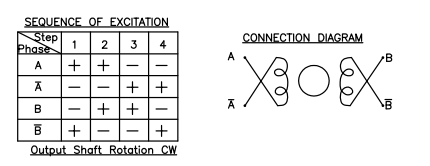
Original English figure 6, PDF page 85
Excitation sequence; output shaft rotation CW.
| Phase / step | 1 | 2 | 3 | 4 |
|---|---|---|---|---|
| A | + | + | − | − |
| A̅ | − | − | + | + |
| B | − | + | + | − |
| B̅ | + | − | − | + |
1.3) To obtain the enable pin, MP6507 needs to use 4 PWMs to generate stepper motor control waveforms. Due to the limited hardware PWM, the focus, zoom, and P iris stepper motors each use a MP6507 driver to drive, so use gpio to enable It can correspond to the MP6507 driver, so as to realize PWM time-sharing multiplexing. Of course, this also has a drawback. Only one stepper motor can be driven at the same time, and the other two stepper motors need to wait for the end of the previous operation to continue operation; 1.4) Obtain hardware-related constraints and resources such as the maximum step, maximum starting speed, maximum operating speed, acceleration curve data of each motor;
2. hrtimer_init, timer initialization, pwm uses continuous mode, timer timing is required, after reaching the specified number of output pwm waveforms, the timer interrupt closes pwm, and the acceleration process also needs to enter timing after the specified number of waveforms The device interrupts to modify the pwm frequency, so as to realize the acceleration of the stepper motor;
3. init_completion, the synchronization mechanism is realized through completion, and the next motor operation can only be carried out after the previous motor movement operation ends;
4. Initialization of v4l2 device and media entity.
v4l2 sub-device: v4l2_i2c_subdev_init, the driver requires subdev to have its own device node for user mode rkaiq to access, and realize the control of the motor through this device node;
media entity: media_entity_init;
5. Flash device name:
  snprintf(sd->name, sizeof(sd->name), "m%02d_%s_%s",
           motor->module_index, facing,
           DRIVER_NAME);
2. Implement the v4l2 sub-device driver, which mainly implements the following 2 members:
  struct v4l2_subdev_core_ops
  struct v4l2_ctrl_ops
2.1 Refer to v4l2_subdev_core_ops to explain the implementation of the callback function, which mainly implements the following callback functions:
  .ioctl
  .compat_ioctl32
This callback mainly implements RK private control commands, involving:
| Member name | Description |
|---|---|
| RK_VIDIOC_VCM_TIMEINFO | Focusing time information, used to confirm whether the current frame is the effective frame after focusing |
| RK_VIDIOC_ZOOM_TIMEINFO | Zoom time information, used to confirm whether the current frame is the effective frame after zooming |
| RK_VIDIOC_IRIS_TIMEINFO | Time information of the aperture, used to confirm whether the current frame is the effective frame after aperture adjustment |
| RK_VIDIOC_FOCUS_CORRECTION | Focus position correction (reset) |
| RK_VIDIOC_ZOOM_CORRECTION | Zoom position correction (reset) |
| RK_VIDIOC_IRIS_CORRECTION | Iris position correction (reset) |
2.2 Refer to the description of v4l2_ctrl_ops to implement the callback function, which mainly implements the following callback functions:
.g_volatile_ctrl
.s_ctrl
.g_volatile_ctrl and .s_ctrl implement the following commands with standard v4l2 control:
| Parameter name | Description |
|---|---|
| V4L2_CID_FOCUS_ABSOLUTE | Control the focus, 0 means the smallest focal length, clear close up |
| V4L2_CID_ZOOM_ABSOLUTE | Control the zoom factor, 0 means the zoom factor is the smallest and the field of view is the largest |
| V4L2_CID_IRIS_ABSOLUTE | Control the size of the P aperture opening, 0 means the aperture is closed** |
3. Reference for stepping motor acceleration curve:
3.1 Trapezoidal curve You can simply accelerate and decelerate at equal intervals and speeds as shown in the figure.
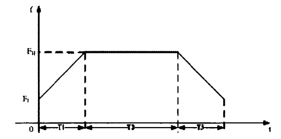
Original English figure 7, PDF page 86
3.2 S-curve
If the trapezoidal acceleration is not ideal, you can consider the S-shaped acceleration, you can refer to the following formula: Speed = Vmin + ((Vmax-Vmin) / (1 + exp(-fac * (i-Num) / Num))); among them, Vmin refers to the motor starting speed Vmax refers to the target speed of the motor fac is the curve coefficient, generally in the range of 4~6, the larger the value, the steeper the middle of the curve i is the speed segment number, if it is divided into 32 segments to accelerate, the value is 0~31 Num is half of the number of speed segments. If divided into 32 segments, num is 16
Original English figure 8, PDF page 87
MS41908 device registration(DTS)
Because some lenses support PIRIS, FOCUS, ZOOM, ZOOM1 or a combination of DC-IRIS, FOCUS, ZOOM, MS41908 is made into PIRIS, FOCUS, ZOOM, ZOOM1, DC-IRIS functions configurable, and can be loaded and driven multiple times to achieve multiple The combination of driver chips will cause dts to be more complicated. Please read the description of each parameter carefully.
  &spi0 {
      status = "okay";
      pinctrl-names = "default";
      pinctrl-0 = <&spi0m0_clk &spi0m0_cs0n &spi0m0_miso &spi0m0_mosi>;
      //If pinctrl is not configured, confirm whether the default pinctrl is the actual pin group
      assigned-clocks = <&pmucru CLK_SPI0>;
      assigned-clock-rates = <100000000>;
      ms41908: ms41908@00 {
          status = "okay";
          compatible = "relmon,ms41908";
          reg = <0>;
          pinctrl-names = "default";
          focus-start-up-speed = <800>;
          zoom-start-up-speed = <800>;
          focus-step-max = <3160>;
          zoom-step-max = <1520>;
          focus-backlash = <18>;
          vd_fz-period-us = <10000>;
          vd_fz-gpios = <&gpio3 RK_PC6 GPIO_ACTIVE_HIGH>;
          rockchip,camera-module-index = <1>;
          rockchip,camera-module-facing = "front";
          use-focus;
          use-zoom;
          focus-used-pin = "cd";
          zoom-used-pin = "ab";
      };
  };
  &i2c1 {
      imx335: imx335@1a{
          ...
          lens-focus = <&ms41908>;
          //Multiple device registration,lens-focus = <&ms41908_0 &ms41908_1>;
          ...
      };
  };
Basic description:
| Member name | description |
|---|---|
| pinctrl-0 | SPI pin definition, according to the actual pin configuration, the pin can be mapped to the spi function ag. pinctrl-0 = <&spi0m0_clk &spi0m0_cs0n &spi0m0_miso &spi0m0_mosi>; |
| assigned-clocks assigned-clock- rates |
SPI Clock configuration, it is recommended to configure at 100MHz |
| reg | reg = <0>; to use cs0 reg = <1>; to use cs1 |
| rockchip,camera- module-index |
Camera serial number, the field that matches the camera |
| rockchip,camera- module-facing |
Camera orientation, field matching camera |
| reset-gpios | The reset pin of ms41908 can not be configured when the hardware is fixed and pulled up |
| vd_fz-period-us | The pulse signal period required for the update of the stepping motor drive register. The pulse signal of the two stepping motors is the same. The motor running time exceeds the vd period will cause out of step, and the drive will ensure that the motor’s single motion cycle time is within the vd period |
FOCUS description:
| Member name |
description |
|---|---|
| use-focus | Whether to use the focus function |
| focus- used-pin |
Each ms41908 chip can drive two stepping motors, the corresponding pin groups are called “ab” and “cd”, according to the actual hardware connection configuration |
| focus- backlash |
The error caused by the gear gap, the number of steps to be compensated when the motor direction changes, and the data obtained according to the actual lens test |
| focus- start-up- speed |
The starting speed of the stepping motor, in PPS |
| focus- step-max |
The effective movement range of the motor, the unit is the number of steps |
| focus- ppw |
Set ms41908 output pwm duty cycle, 0-255, the larger the value, the stronger the drive capacity, adjust according to the motor load |
| focus- phmode |
Set ms41908 output PWM waveform phase correction, generally not configured, it depends on the situation |
| focus- micro |
Set the number of microsteps, divided into 64, 128, 256 subdivisions, the default is 256 subdivisions |
| focus- reback- distance |
The focus curve needs to go in the same direction for the position to be accurate. For example, the current position is 100. If you want to go back to 90, you need to go back to 80 and then to 90. The position is accurate. The parameter configured here is the number of steps for multiple callbacks. |
| focus-1- 2phase- excitation |
The default motor excitation mode is 2-2 phase excitation, this parameter can be configured using 1-2 phase excitation ag. focus-1-2phase-excitation; |
| focus-dir- opposite |
If the current motor movement direction is opposite to the actual focus curve, this parameter can be configured to reverse the motor movement direction ag. focus-dir-opposite; |
Optocoupler description:
| Member name |
description |
|---|---|
| focus-pic | The C pin of the optocoupler is used to detect the level transition. The junction point of the level transition is the origin point of the optocoupler |
| focus- pia |
The A pin of the optocoupler drives the photodiode. When the optocoupler is calibrated, it should be pulled up, and it should be pulled down during normal operation, otherwise the photodiode will affect the imaging. |
| focus- pie |
When the hardware is designed, it can be directly grounded. If it is designed to be controlled by gpio, it needs to configure the pin to be low level. |
| focus- min-pos |
The number of steps on the left and right of the optocoupler origin needs to be measured, and then filled in dts, which can be larger than actual |
| focus- min-pos |
The number of steps on the left and right of the optocoupler origin needs to be measured, and then filled in dts, which can be larger than actual |
Note: The lens without optocoupler positioning does not need to configure optocoupler parameters.
ZOOM description:
| Member name |
description |
|---|---|
| use-zoom | Whether to use the zoom function |
| zoom- used-pin |
Each ms41908 chip can drive two stepping motors, the corresponding pin groups are called “ab” and “cd”, according to the actual hardware connection configuration |
| zoom- backlash |
The error caused by the gear gap, the number of steps to be compensated when the motor direction changes, and the data obtained according to the test |
| zoom- start-up- speed |
The starting speed of the stepping motor, in PPS |
| zoom- step-max |
The effective movement range of the motor, the unit is the number of steps |
| zoom- ppw |
Set ms41908 output pwm duty cycle, 0-255, the larger the value, the stronger the drive capacity, adjust according to the motor load |
| zoom- phmode |
Set ms41908 output PWM waveform phase correction, generally not configured, it depends on the situation |
| zoom- micro |
Set the number of microsteps, divided into 64, 128, 256 subdivisions, the default is 256 subdivisions |
| zoom-1- 2phase- excitation |
The default motor excitation mode is 2-2 phase excitation, this parameter can be configured using 1-2 phase excitation ag. zoom-1-2phase-excitation; |
| zoom-dir- opposite |
If the current motor movement direction is opposite to the actual focus curve, this parameter can be configured to reverse the motor movement direction ag. zoom-dir-opposite; |
Optocoupler description:
| Member name |
description |
|---|---|
| zoom- pic |
The C pin of the optocoupler is used to detect the level transition. The junction point of the level transition is the origin point of the optocoupler |
| zoom- min-pos |
The number of steps on the left and right of the optocoupler origin needs to be measured, and then filled in dts, which can be larger than actual |
| zoom- min-pos |
The number of steps on the left and right of the optocoupler origin needs to be measured, and then filled in dts, which can be larger than actual |
Note: The lens without optocoupler positioning does not need to configure optocoupler parameters.
ZOOM1 description:
| Member name |
description |
|---|---|
| use- zoom1 |
Whether to use the function of zoom1, some lenses support the control of 2 zooms |
| zoom1- used-pin |
Each ms41908 chip can drive two stepping motors, the corresponding pin groups are called “ab” and “cd”, according to the actual hardware connection configuration |
| zoom1- backlash |
The error caused by the gear gap, the number of steps to be compensated when the motor direction changes, and the data obtained according to the test |
| zoom1- start-up- speed |
The starting speed of the stepping motor, in PPS |
| zoom1- step-max |
The effective movement range of the motor, the unit is the number of steps |
| zoom1- ppw |
Set ms41908 output pwm duty cycle, 0-255, the larger the value, the stronger the drive capacity, adjust according to the motor load |
| zoom1- phmode |
Set ms41908 output PWM waveform phase correction, generally not configured, it depends on the situation |
| zoom1- micro |
Set the number of microsteps, divided into 64, 128, 256 subdivisions, the default is 256 subdivisions |
| zoom1-1- 2phase- excitation |
The default motor excitation mode is 2-2 phase excitation, this parameter can be configured using 1-2 phase excitation ag. zoom1-1-2phase-excitation; |
| zoom1- dir- opposite |
If the current motor movement direction is opposite to the actual focus curve, this parameter can be configured to reverse the motor movement direction ag. zoom1-dir-opposite; |
Optocoupler description:
| Member name |
description |
|---|---|
| zoom1- pic |
The C pin of the optocoupler is used to detect the level transition. The junction point of the level transition is the origin point of the optocoupler |
| zoom1- pia |
The A pin of the optocoupler drives the photodiode. When the optocoupler is calibrated, it should be pulled up, and it should be pulled down during normal operation, otherwise the photodiode will affect the imaging. |
| zoom1- pie |
When the hardware is designed, it can be directly grounded. If it is designed to be controlled by gpio, it needs to configure the pin to be low level. |
| zoom1- min-pos |
The number of steps on the left and right of the optocoupler origin needs to be measured, and then filled in dts, which can be larger than actual |
| zoom1- min-pos |
The number of steps on the left and right of the optocoupler origin needs to be measured, and then filled in dts, which can be larger than actual |
Note: The lens without optocoupler positioning does not need to configure optocoupler parameters.
PIRIS description:
| Member name |
description |
|---|---|
| use-p-iris | Whether to use the function of P-IRIS |
| piris- used-pin |
Each ms41908 chip can drive two stepping motors, the corresponding pin groups are called “ab” and “cd”, according to the actual hardware connection configuration |
| piris- backlash |
The error caused by the gear gap, the number of steps to be compensated when the motor direction changes, and the data obtained according to the actual lens test |
| piris- start-up- speed |
The starting speed of the stepping motor, in PPS |
| piris- step-max |
The effective movement range of the motor, the unit is the number of steps |
| piris-ppw | Set ms41908 output pwm duty cycle, 0-255, the larger the value, the stronger the drive capacity, adjust according to the motor load |
| piris- phmode |
Set ms41908 output PWM waveform phase correction, generally not configured, it depends on the situation |
| piris- micro |
Set the number of microsteps, divided into 64, 128, 256 subdivisions, the default is 256 subdivisions |
| piris-1- 2phase- excitation |
The default motor excitation mode is 2-2 phase excitation, this parameter can be configured using 1-2 phase excitation ag. piris-1-2phase-excitation; |
| piris-dir- opposite |
If the current motor movement direction is opposite to the actual focus curve, this parameter can be configured to reverse the motor movement direction ag. piris-dir-opposite; |
Optocoupler description:
| Member name |
description |
|---|---|
| piris-pic | The C pin of the optocoupler is used to detect the level transition. The junction point of the level transition is the origin point of the optocoupler |
| piris-pia | The A pin of the optocoupler drives the photodiode. When the optocoupler is calibrated, it should be pulled up, and it should be pulled down during normal operation, otherwise the photodiode will affect the imaging. |
| piris-pie | When the hardware is designed, it can be directly grounded. If it is designed to be controlled by gpio, it needs to configure the pin to be low level. |
| piris- min-pos |
The number of steps on the left and right of the optocoupler origin needs to be measured, and then filled in dts, which can be larger than actual |
| piris- min-pos |
The number of steps on the left and right of the optocoupler origin needs to be measured, and then filled in dts, which can be larger than actual |
Note: The lens without optocoupler positioning does not need to configure optocoupler parameters.
DCIRIS description:
| Member name |
description |
|---|---|
| use-dc- iris |
Whether to use the function of DC-IRIS |
| vd_iris- gpios |
Synchronous pulse pin for DC aperture related registers to take effect |
| dc-iris- reserved- polarity |
DC aperture polarity setting, if 0 means the aperture is fully open, you can set this property to reverse |
| dc-iris- max-log |
The target value range of the DC iris is 0~1023, the actual effective range may be relatively small, this parameter can be configured to limit the effective range |
Brief description of data type
struct spi_driver
[Description]
Define platform device driver information
[Definition]
  struct spi_driver {
          int (*probe)(struct spi_device *spi);
          int (*remove)(struct spi_device *spi);
          struct device_driver driver;
          const struct spi_device_id *id_table;
  };
[Key Member]
| Member name |
description |
|---|---|
| @driver | struct device_driver driver mainly contains the name of the driver and of_match_table for matching with DTS registered devices. When the compatible field in of_match_table matches the compatible field in the dts file, the .probe function will be called |
| @id_table | If the kernel does not use of_match_table and dts registered equipment for matching, the kernel uses the table for matching |
| @probe | Callback for device binding |
| @remove | Callback for device unbinding |
[Example]
  static const struct spi_device_id motor_match_id[] = {
      {"relmon,ms41908", 0 },
      { }
  };
  static struct spi_driver motor_dev_driver = {
      .driver = {
          .name = DRIVER_NAME,
          .of_match_table = of_match_ptr(motor_dev_of_match),
      },
      .probe      = &motor_dev_probe,
      .remove     = &motor_dev_remove,
      .id_table   = motor_match_id,
  };
struct v4l2_subdev_core_ops
[Description]
Define core ops callbacks for subdevs.
[Definition]
  struct v4l2_subdev_core_ops {
      ……
      long (*ioctl)(struct v4l2_subdev *sd, unsigned int cmd, void *arg);
  #ifdef CONFIG_COMPAT
      long (*compat_ioctl32)(struct v4l2_subdev *sd, unsigned int cmd,
               unsigned long arg);
  #endif
      ……
  };
[Key Member]
| Member name | description |
|---|---|
| .ioctl | called at the end of ioctl() syscall handler at the V4L2 core.used to provide support for private ioctls used on the driver. |
| .compat_ioctl32 | called when a 32 bits application uses a 64 bits Kernel, in order to fix data passed from/to userspace.in order to fix data passed from/to userspace. |
[Example]
  static const struct v4l2_subdev_core_ops motor_core_ops = {
      .ioctl = motor_ioctl,
  };
  static const struct v4l2_subdev_ops motor_subdev_ops = {
      .core   = &motor_core_ops,
  };
struct v4l2_ctrl_ops
[Description]
The control operations that the driver has to provide.
[Definition]
  struct v4l2_ctrl_ops {
      int (*g_volatile_ctrl)(struct v4l2_ctrl *ctrl);
      int (*s_ctrl)(struct v4l2_ctrl *ctrl);
  };
[Key Member]
| Member name |
description |
|---|---|
| .g_volatile_ctrl | Get a new value for this control. Generally only relevantfor volatile (and usually read-only) controls such as a control that returns the current signal strength which changes continuously. |
| .s_ctrl | Actually set the new control value. s_ctrl is compulsory. The ctrl->handler- >lock is held when these ops are called, so no one else can access controls owned by that handler. |
[Example]
  static const struct v4l2_ctrl_ops motor_ctrl_ops = {
      .s_ctrl = motor_s_ctrl,
  };
API brief description
xxxx_set_ctrl
[description]
Call standard v4l2_control to set focus, zoom, P aperture position
The driver implements the following v4l2 standard commands:
| Parameter name | Description |
|---|---|
| V4L2_CID_FOCUS_ABSOLUTE | Control the focus, 0 means the minimum focal length, clear near |
| V4L2_CID_ZOOM_ABSOLUTE | Control the zoom factor, 0 means the zoom factor is the smallest and the angle of view is the largest |
| V4L2_CID_IRIS_ABSOLUTE | Control the size of the aperture opening, 0 means the aperture is closed |
| V4L2_CID_ZOOM_CONTINUOUS | Control the zoom factor zoom1, used when multiple zoom groups are controlled |
[grammar]
static int xxxx_set_ctrl(struct v4l2_ctrl *ctrl)
[parameter]
| Parameter name | Description | Input and output |
|---|---|---|
| *ctrl | v4l2 control structure pointer | input |
xxxx_ioctl xxxx_compat_ioctl
[description]
The realization function of custom ioctl mainly includes the time information of obtaining focus, zoom and P aperture (time stamp of start and end movement). Since the lens used does not have a positioning device, it is necessary to reset the position of the lens motor when necessary .
The driver implements custom commands::
| Parameter name | Description |
|---|---|
| RK_VIDIOC_VCM_TIMEINFO | Focusing time information, used to confirm whether the current frame is the effective frame after focusing |
| RK_VIDIOC_ZOOM_TIMEINFO | Time information of zooming, used to confirm whether the current frame is the effective frame after zooming is completed |
| RK_VIDIOC_IRIS_TIMEINFO | The time information of the aperture, used to confirm whether the current frame is the effective frame after P aperture adjustment |
| RK_VIDIOC_ZOOM1_TIMEINFO | When there are multiple zoom groups, the time information of zoom1 is used to confirm whether the current frame is the effective frame after zooming is completed |
| RK_VIDIOC_IRIS_CORRECTION | Aperture position reset, only works on P-IRIS |
| RK_VIDIOC_FOCUS_CORRECTION | Focus position reset |
| RK_VIDIOC_ZOOM_CORRECTION | Zoom position reset |
| RK_VIDIOC_ZOOM1_CORRECTION | Double zoom lens, the second group of zoom position reset |
| RK_VIDIOC_FOCUS_SET_POSITION | Set the focus position |
| RK_VIDIOC_ZOOM_SET_POSITION | Set the follow focus parameters and realize multi-step zoom and focus linkage according to the zoom curve |
Note:
1. In order to solve the problem of the inaccuracy of the absolute position of the motor caused by the gear gap, by fixing one direction as the positive direction and the other as the negative direction, the initial position of the gear is stuck in the positive direction. When the motor goes in the negative direction, it must go more than the gear. The number of clearance steps is n, and then the number of steps in the positive direction is n, so that the gear can remain stuck in the positive direction, which is called callback. The callback ensures the accuracy of the absolute position. However, the number of callback steps is greater than the gear gap. During manual focusing or automatic focusing, if you move in the negative direction for multiple times, the continuous callback will give people the feeling of jitters, so you cannot callback every time you move in the negative direction. The newly added RK_VIDIOC_FOCUS_SET_POSITION and RK_VIDIOC_ZOOM_SET_POSITION interfaces are determined by the af algorithm whether to call back. The standard v4l2 commands V4L2_CID_FOCUS_ABSOLUTE and V4L2_CID_ZOOM_ABSOLUTE do not call back and are only used in manual mode. RK_VIDIOC_ZOOM_SET_POSITION contains focus and zoom parameters. The focus is adjusted synchronously during the zooming process to make the picture excessively natural.
2. In order to solve the gear gap in the early stage, by configuring the focus-backlash, when walking in the negative direction, take more steps of the gear gap to offset the gear gap. However, due to the individual difference of the lens gear gap, there is an error in the calibration and the calibration workload Is large, so this parameter is discarded. The drive retains its design, and it can still be used if the position accuracy of the motor is not high.
[grammar]
  static int xxxx_ioctl(struct v4l2_subdev *sd, unsigned int cmd, void *arg)
  static long xxxx_compat_ioctl32(struct v4l2_subdev *sd, unsigned int cmd,
  unsigned long arg)
[parameter]
| Parameter name | Description | Input and output |
|---|---|---|
| *sd | v4l2 subdev structure pointer | input |
| cmd | ioctl command | input |
| *arg/arg | Parameter pointer | output |
[return value]
| Return value | Description |
|---|---|
| 0 | Success |
| Not 0 | Failed |
Drive migration steps
For SPI controlled driver chips, you can use the SPI framework for device driver migration, MS41908 as a reference. Driver reference: /kernel/drivers/media/spi/ms41908.c
The migration steps are as follows:
1.Implement the standard spi sub-device driver part.
1.1 According to the description of struct spi_driver,the following parts are mainly realized:
struct driver.name
struct driver. of_match_table
probe function
remove function
1.2 Probe function implementation details description:
1) Equipment resource acquisition, mainly to obtain DTS resources, reference MS41908 device registration(DTS);
1.1) RK private resource definition, naming methods such as rockchip, camera-module-xxx, mainly to provide equipment parameters and Camera equipment to match.
1.2) Obtain motor-related configuration parameters, which are defined according to the function requirements of the chip, and try to make the parameters related to motor motion configurable.
2. hrtimer_init,Timer initialization, ms41908 uses the vd signal as the trigger signal. The timer is used to fix the period of each vd, which is convenient for operation. The register of ms41908 takes effect after the vd signal. Every time the register value needs to be modified, it can be advanced before the vd signal. Configuration register. It should be noted that the movement speed and the number of movement steps configured by the register must be within the range of the vd period, and the number of steps that exceed the vd period will be lost.
3)init_completion,The synchronization mechanism is realized through completion. For the same motor, the next operation can only be performed after the previous operation is over.
4. Initialization of v4l2 device and media entity
v4l2 sub-device: v4l2_i2c_subdev_init, the driver requires subdev to have its own device node for user mode rkaiq to access, and realize the control of the motor through this device node;
media entity: media_entity_init;
5. Device name:
  snprintf(sd->name, sizeof(sd->name), "m%02d_%s_%s",
           motor->module_index, facing,
           DRIVER_NAME);
2.Implement v4l2 sub-device driver, mainly implement the following 2 members:
  struct v4l2_subdev_core_ops
  struct v4l2_ctrl_ops
2.1 Refer to v4l2_subdev_core_ops instructions to implement the callback function, mainly implement the following callback functions:
  .ioctl
  .compat_ioctl32
2.2 Refer to v4l2_ctrl_ops instructions to implement the callback function, mainly implement the following callback functions:
.g_volatile_ctrl
.s_ctrl
DC-IRIS drive
Compared with P-IRIS, DC-IRIS cannot accurately know the size of the aperture opening. Generally, the scene is fully opened by default. When the exposure is adjusted to the minimum, the image is still overexposed, and then enters the aperture adjustment. When the exposure is set to the maximum, the image is still Under exposure, enter the aperture adjustment. The DC- IRIS motor is a DC motor, which buffers the adjustment speed of the motor through the negative feedback of the Hall device. For the drive, as long as the motor is controlled by a PWM, when the PWM duty cycle is less than 20%, the iris will slowly close until it is completely closed. The smaller the duty cycle, the faster the iris closes; when the duty cycle is greater than The 40% aperture will slowly open, the larger the duty cycle, the faster the opening speed; the aperture in the 20%~40% range is in a hold state. The 20% and 40% here are not fixed values, which are related to the frequency of pwm and the accuracy of the actual hardware devices. Reference driver: /kernel/drivers/media/i2c/hall-dc-motor.c
DC-IRIS Device Registration (DTS)
  hal_dc_motor: hal_dc_motor{
          status = "okay";
          compatible = "rockchip,hall-dc";
          pwms = <&pwm6 0 2500 0>;
          rockchip,camera-module-index = <1>;
          rockchip,camera-module-facing = "front";
  };
  &pwm6 {
          status = "okay";
          pinctrl-names = "active";
          pinctrl-0 = <&pwm6m0_pins_pull_down>;
  };
  &i2c1 {
      imx334: imx334@1a {
          ...
          lens-focus = <&hal_dc_motor>;
          ...
      }
  }
Brief description of data type
struct platform_driver
[Description]
Define platform device driver information
[Definition]
  struct platform_driver {
          int (*probe)(struct platform_device *);
          int (*remove)(struct platform_device *);
          void (*shutdown)(struct platform_device *);
          int (*suspend)(struct platform_device *, pm_message_t state);
          int (*resume)(struct platform_device *);
          struct device_driver driver;
          const struct platform_device_id *id_table;
          bool prevent_deferred_probe;
  };
[Key Member]
| Member name |
Description |
|---|---|
| @driver | struct device_driver driver mainly contains the name of the driver and of_match_table for matching with DTS registered devices. When the compatible field in of_match_table matches the compatible field in the dts file, the .probe function will be called |
| @id_table | If the kernel does not use of_match_table and dts registered equipment for matching, the kernel uses the table for matching |
| @probe | Callback for device binding |
| @remove | Callback for device unbinding |
[Example]
  #if defined(CONFIG_OF)
  static const struct of_device_id motor_dev_of_match[] = {
      { .compatible = "rockchip,hall-dc", },
      {},
  };
  #endif
  static struct platform_driver motor_dev_driver = {
      .driver = {
          .name = DRIVER_NAME,
          .owner = THIS_MODULE,
          .of_match_table = of_match_ptr(motor_dev_of_match),
      },
      .probe = motor_dev_probe,
      .remove = motor_dev_remove,
  };
  module_platform_driver(motor_dev_driver);
struct v4l2_subdev_core_ops
[Description]
Define core ops callbacks for subdevs.
[Definition]
  struct v4l2_subdev_core_ops {
      ……
      long (*ioctl)(struct v4l2_subdev *sd, unsigned int cmd, void *arg);
  #ifdef CONFIG_COMPAT
      long (*compat_ioctl32)(struct v4l2_subdev *sd, unsigned int cmd,
               unsigned long arg);
  #endif
      ……
  };
[Key Member]
| Member name | Description |
|---|---|
| .ioctl | called at the end of ioctl() syscall handler at the V4L2 core.used to provide support for private ioctls used on the driver. |
| .compat_ioctl32 | called when a 32 bits application uses a 64 bits Kernel, in order to fix data passed from/to userspace.in order to fix data passed from/to userspace. |
[Example]
  static const struct v4l2_subdev_core_ops motor_core_ops = {
      .ioctl = motor_ioctl,
  };
  static const struct v4l2_subdev_ops motor_subdev_ops = {
      .core   = &motor_core_ops,
  };
struct v4l2_ctrl_ops
[Description]
The control operations that the driver has to provide.
[Definition]
  struct v4l2_ctrl_ops {
      int (*s_ctrl)(struct v4l2_ctrl *ctrl);
  };
[Key Member]
| Member name |
Description |
|---|---|
| .s_ctrl | Actually set the new control value. s_ctrl is compulsory. The ctrl->handler->lock is held when these ops are called, so no one else can access controls owned by that handler. |
[Example]
  static const struct v4l2_ctrl_ops motor_ctrl_ops = {
      .s_ctrl = motor_s_ctrl,
  };
API brief description
xxxx_set_ctrl
[description]
Call the standard v4l2_control iris position, the DC iris actually cannot know the specific position of the iris, the value set here is the duty ratio of pwm.
The following v4l2 standard commands are implemented:
| Parameter name | Description |
|---|---|
| V4L2_CID_IRIS_ABSOLUTE | Set the duty cycle of pwm that controls the iris, range (0~100) |
[grammar]
static int xxxx_set_ctrl(struct v4l2_ctrl *ctrl)
[parameter]
| Parameter name | Description | Input and output |
|---|---|---|
| *ctrl | v4l2 control structure pointer | input |
[return value]
| Return value | Description |
|---|---|
| 0 | Success |
| Not 0 | Failed |
xxxx_ioctl xxxx_compat_ioctl
[description]
Currently, there is no private definition to be implemented, and v4l2 framework registration is required to implement empty functions.
[grammar]
  static int xxxx_ioctl(struct v4l2_subdev *sd, unsigned int cmd, void *arg)
  static long xxxx_compat_ioctl32(struct v4l2_subdev *sd, unsigned int cmd,
  unsigned long arg)
[parameter]
| Parameter name | Description | Input and output |
|---|---|---|
| *sd | v4l2 subdev structure pointer | input |
| cmd | ioctl command | input |
| *arg/arg | Parameter pointer | Output |
[return value]
| Return value | Description |
|---|---|
| 0 | Success |
| Not 0 | Failed |
Drive migration steps
Driver reference: /kernel/drivers/media/i2c/hall-dc-motor.c
The migration steps are as follows:
1. Implement the standard platform sub-device driver part.
1.1 According to the description of struct platform_driver, the following parts are mainly realized:
struct driver.name
struct driver. of_match_table
probe function
remove function
1.2 Detailed description of the probe function implementation:
1. Device resource acquisition, mainly to obtain DTS resources, refer to DC-IRIS Device Registration (DTS);
1.1) RK private resource definition, naming methods such as rockchip, camera-module-xxx, mainly to provide equipment parameters and Camera equipment to match. To 1.2) To obtain pwm resources, pay attention to whether the pwm node is enabled.
2. Initialization of v4l2 device and media entity.
v4l2 sub-device: v4l2_i2c_subdev_init, the driver requires subdev to have its own device node for user mode rkaiq to access, and realize the control of the motor through this device node;
media entity: media_entity_init;
3. Flash device name:
  snprintf(sd->name, sizeof(sd->name), "m%02d_%s_%s",
           motor->module_index, facing,
           DRIVER_NAME);
2. Implement the v4l2 sub-device driver, which mainly implements the following 2 members:
  struct v4l2_subdev_core_ops
  struct v4l2_ctrl_ops
2.1 Refer to v4l2_subdev_core_ops to explain the implementation of the callback function, which mainly implements the following callback functions:
  ioctl
  .compat_ioctl32
The callback currently does not need to implement specific commands, but as a sub-device of v4l2, the operation function must be implemented, so an empty function is implemented here.
2.2 Refer to the description of v4l2_ctrl_ops to implement the callback function, which mainly implements the following callback functions:
.g_volatile_ctrl.s_ctrl
.g_volatile_ctrl and .s_ctrl implement the following commands with standard v4l2 control:
| Member name | Description |
|---|---|
| V4L2_CID_IRIS_ABSOLUTE | Set the duty cycle of pwm that controls the iris, range (0~100) |
RK-IRCUT driver
The IRCUT is controlled by two wires. A 3.5v~6v power supply is applied to the two wires. The IRCUT can be switched by reversing the positive and negative poles of the IRCUT power supply and meeting the power-on time of 100ms±10%. The driver controls the current output direction of the motor driver through two gpio. The gpio commands are open (red line) and close (black line). The current flows from open to close, which is the infrared cut filter, working during the day; the current flows from close to open, which is a white glass sheet and works at night.
RK-IRCUT Device Registration (DTS)
  cam_ircut0: cam_ircut {
          status = "okay";
          compatible = "rockchip,ircut";
          ircut-open-gpios = <&gpio2 RK_PA7 GPIO_ACTIVE_HIGH>;
          ircut-close-gpios  = <&gpio2 RK_PA6 GPIO_ACTIVE_HIGH>;
          rockchip,camera-module-index = <1>;
          rockchip,camera-module-facing = "front";
  };
  &i2c1 {
      imx334: imx334@1a {
          ...
          ir-cut = <&cam_ircut0>;
          ...
      }
  }
Brief description of data type
struct platform_driver
[Description]
Define platform device driver information
[Definition]
  struct platform_driver {
          int (*probe)(struct platform_device *);
          int (*remove)(struct platform_device *);
          void (*shutdown)(struct platform_device *);
          int (*suspend)(struct platform_device *, pm_message_t state);
          int (*resume)(struct platform_device *);
          struct device_driver driver;
          const struct platform_device_id *id_table;
          bool prevent_deferred_probe;
  };
[Key Member]
| Member name |
Description |
|---|---|
| @driver | struct device_driver driver mainly contains the name of the driver and of_match_table for matching with DTS registered devices. When the compatible field in of_match_table matches the compatible field in the dts file, the .probe function will be called |
| @id_table | If the kernel does not use of_match_table and dts registered equipment for matching, the kernel uses the table for matching |
| @probe | Callback for device binding |
| @remove | Callback for device unbinding |
[Example]
  #if defined(CONFIG_OF)
  static const struct of_device_id ircut_of_match[] = {
      { .compatible = "rockchip,ircut", },
      {},
  };
  #endif
  static struct platform_driver ircut_driver = {
      .driver = {
          .name = RK_IRCUT_NAME,
          .of_match_table = of_match_ptr(ircut_of_match),
      },
      .probe = ircut_probe,
      .remove = ircut_drv_remove,
  };
  module_platform_driver(ircut_driver);
struct v4l2_subdev_core_ops
[Description]
Define core ops callbacks for subdevs.
[Definition]
  struct v4l2_subdev_core_ops {
      ……
      long (*ioctl)(struct v4l2_subdev *sd, unsigned int cmd, void *arg);
  #ifdef CONFIG_COMPAT
      long (*compat_ioctl32)(struct v4l2_subdev *sd, unsigned int cmd,
               unsigned long arg);
  #endif
      ……
  };
[Key Member]
| Member name | Description |
|---|---|
| .ioctl | called at the end of ioctl() syscall handler at the V4L2 core.used to provide support for private ioctls used on the driver. |
| .compat_ioctl32 | called when a 32 bits application uses a 64 bits Kernel, in order to fix data passed from/to userspace.in order to fix data passed from/to userspace. |
[Example]
  static const struct v4l2_subdev_core_ops ircut_core_ops = {
      .ioctl = ircut_ioctl,
  };
  static const struct v4l2_subdev_ops ircut_subdev_ops = {
      .core   = &ircut_core_ops,
  };
struct v4l2_ctrl_ops
[Description]
The control operations that the driver has to provide.
[Definition]
  struct v4l2_ctrl_ops {
      int (*s_ctrl)(struct v4l2_ctrl *ctrl);
  };
[Key Member]
| Member name |
Description |
|---|---|
| .s_ctrl | Actually set the new control value. s_ctrl is compulsory. The ctrl->handler->lock is held when these ops are called, so no one else can access controls owned by that handler. |
[Example]
  static const struct v4l2_ctrl_ops ircut_ctrl_ops = {
      .s_ctrl = ircut_s_ctrl,
  };
API brief description
xxxx_set_ctrl
[description]
Call standard v4l2_control to switch IRCUT.
The following v4l2 standard commands are implemented:
| Parameter name | Description |
|---|---|
| V4L2_CID_BAND_STOP_FILTER | 0 is CLOSE state, infrared light can enter; 3 is OPEN state, infrared light cannot enter; |
[grammar]
static int xxxx_set_ctrl(struct v4l2_ctrl *ctrl)
[parameter]
| Parameter name | Description | Input and output |
|---|---|---|
| *ctrl | v4l2 control structure pointer | input |
[return value]
| Return value | Description |
|---|---|
| 0 | Success |
| Not 0 | Failed |
xxxx_ioctl xxxx_compat_ioctl
[description]
Currently, there is no private definition to be implemented, and v4l2 framework registration is required to implement empty functions.
[grammar]
  static int xxxx_ioctl(struct v4l2_subdev *sd, unsigned int cmd, void *arg)
  static long xxxx_compat_ioctl32(struct v4l2_subdev *sd, unsigned int cmd,
  unsigned long arg)
[parameter]
| Parameter name | Description | Input and output |
|---|---|---|
| *sd | v4l2 subdev structure pointer | input |
| cmd | ioctl command | input |
| *arg/arg | Parameter pointer | Output |
[return value]
| Return value | Description |
|---|---|
| 0 | Success |
| Not 0 | Failed |
Drive migration steps
Driver reference: /kernel/drivers/media/i2c/rk_ircut.c
The migration steps are as follows:
1. Implement the standard platform sub-device driver part.
1.1 According to the description of struct platform_driver, the following parts are mainly realized:
struct driver.name
struct driver. of_match_table
probe function
remove function
1.2 Detailed description of the probe function implementation:
1. Equipment resource acquisition, mainly to obtain DTS resources, refer to RK-IRCUT Equipment Registration (DTS);
1.1) RK private resource definition, naming methods such as rockchip, camera-module-xxx, mainly to provide equipment parameters and Camera equipment to match.
1.2) Get open and close gpio resources;
2. init_completion, the synchronization mechanism is realized through completion. Since it takes about 100ms to switch the IRCUT, the completion synchronization mechanism is required to ensure that the last IRCUT switch has been completed before the operation can be performed again;
3. Create a work queue and place the switching operation on the work queue to avoid long- term blocking;
4. Initialization of v4l2 device and media entity.
v4l2 sub-device: v4l2_i2c_subdev_init, the driver requires subdev to have its own device node for user-mode rkaiq to access, and control IRCUT through this device node;
media entity: media_entity_init;
  sd->entity.function = MEDIA_ENT_F_LENS;
  sd->entity.flags = 1;//flag is fixed to 1, used to distinguish other sub-devices of MEDIA_ENT_F_LENS type
5. Device name:
  snprintf(sd->name, sizeof(sd->name), "m%02d_%s_%s",
           ircut->module_index, facing,
           RK_IRCUT_NAME);
2. Implement the v4l2 sub-device driver, which mainly implements the following 2 members:
  struct v4l2_subdev_core_ops
  struct v4l2_ctrl_ops
2.1 Refer to v4l2_subdev_core_ops to explain the implementation of the callback function, which mainly implements the following callback functions:
  .ioctl
  .compat_ioctl32
This callback currently does not need to implement private commands, but v4l2 framework registration requires it, so an empty function is implemented, and the content of the function can be supplemented according to needs in the future.
2.2 Refer to the description of v4l2_ctrl_ops to implement the callback function, which mainly implements the following callback functions:
.s_ctrl
.s_ctrl implements the following commands with standard v4l2 control:
| Member name | Description |
|---|---|
| V4L2_CID_BAND_STOP_FILTER | 0 is CLOSE state, infrared light can enter; 3 is OPEN state, infrared light cannot enter; |
media-ctl v4l2-ctl tool
The media-ctl tool operates through media devices such as /dev/medio0. It manages the format, size, and link of each node in the Media topology.
The v4l2-ctl tool is for video devices such as /dev/video0 and /dev/video1. It performs a series of operations such as set_fmt, reqbuf, qbuf, dqbuf, stream_on, stream_off, etc. on the video device.
For specific usage, please refer to the help information of the command. The following are some common usages.
1. Print topology
media-ctl -p -d /dev/media0
Note: There are many device nodes in isp2, and media0/media1/media2 nodes may exist. You need to enumerate and view device information one by one.
2. Link
  media-ctl -l'"rkisp-isp-subdev":2->"rkisp-bridge-ispp":0[0]'
  media-ctl -l'"rkisp-isp-subdev":2->"rkisp_mainpath":0[1]'
Note: Disconnect the path of ispp, link to main_path, grab the raw image from main_path, media- ctl does not add -d to specify the device, the default is /dev/media0 device, you need to confirm which device rkisp-isp-subdev is hung on On the node, it is usually /dev/media1.
3. Modify fmt/size
  media-ctl -d /dev/media0 \
  --set-v4l2'"ov5695 7-0036":0[fmt:SBGGR10_1X10/640x480]'
Note: You need to confirm which media device the camera device node (ov5695 7-0036) is mounted on.
4. Set fmt and grab the frame
  v4l2-ctl -d /dev/video0 \
  --set-fmt-video=width=720,height=480,pixelformat=NV12 \
  --stream-mmap=3 \
  --stream-skip=3 \
  --stream-to=/tmp/cif.out \
  --stream-count=1 \
  --stream-poll
5. Set exposure, gain and other controls
v4l2-ctl -d /dev/video3 --set-ctrl'exposure=1216,analogue_gain=10'
Note: The isp driver will call the control command of the camera sub-device, so the specified device as video3 (main_path or self_path) can be set to exposure, vicap will not call the control command of the camera sub-device, and setting the control command directly on the acquisition node will fail. The correct way is to find the camera device node is /dev/v4l-subdevX and directly configure the terminal node.
RV1109/RV1126 Memory Optimization Guide
MIPI -> DDR_1 -> ISP -> DDR_2 -> ISPP(TNR) -> DDR_3 -> ISPP(NR&Sharp) -> DDR_4 -> ISPP(FEC) -> DDR_5
1. DDR_1: Vicap raw data is written to ddr, or isp mipi raw data is written to ddr, and isp reads raw data from ddr for processing
Occupied memory: buf_cnt * buf_size * N, (N = 1: linear mode, 2: hdr2 frame mode 3: hdr3 frame mode).
buf_size: ALIGN(width * bpp / 8, 256) * height; //bpp is the bit width, raw8 raw10 or raw12
buf_cnt: 4 by default, define the aiq library code hwi/isp20/CamHwIsp20.h, 3 at least.
#define ISP_TX_BUF_NUM 4
#define VIPCAP_TX_BUF_NUM 4
2. DDR_2: isp fbc yuv420 and gain data are written to ddr, and ispp reads from ddr for processing
Occupied memory: buf_size * buf_cnt
buf_size: ALIGN(width, 64) * ALIGN(height, 128) / 16 + ALIGN(width, 16) * ALIGN(hieght, 16) * 1.5625
buf_cnt: 4 bufs in tnr 3to1 mode, 3 bufs in 2to1 mode, the mode is configured in iq xml
3. DDR_3: ispp tnr fbc yuv420 and gain data written to ddr, ispp NR&Sharp reads and processes from ddr again
Occupied memory: buf_size * buf_cnt
buf_size: ALIGN(width, 64) * ALIGN(height, 128) / 16 + ALIGN(width, 16) * ALIGN(hieght, 16) * 1.5625
buf_cnt: 2, which is the smallest
4. DDR_4: ispp NR&Sharp yuyv data is written to ddr, and ispp fec is read from ddr for
Occupied memory: buf_size * buf_cnt (fec function does not open and does not occupy memory)
buf_size: width * height * 2
buf_cnt: 2, which is the smallest
5. DDR_5: ispp 4-channel output image buffer, the buffer size is calculated according to the resolution, format and buf_cnt set by the user
The above buf_cnt is where the memory can be optimally configured
isp cma memory reserved size, can configure more memory and get the actual size after camera app running.
  isp_reserved: isp {
      compatible = "shared-dma-pool";
      inactive;
      reusable;
      size = <0x10000000>;//256M and need 4M align
  };
  enable cma debug
  +++ b/arch/arm/configs/rv1126_defconfig
  @@ -62,6 +62,8 @@ CONFIG_IOSCHED_BFQ=y
   CONFIG_KSM=y
   CONFIG_DEFAULT_MMAP_MIN_ADDR=32768
   CONFIG_CMA=y
  +CONFIG_CMA_DEBUG=y
  +CONFIG_CMA_DEBUGFS=y
  one page is 4K, 26091 page is 104364K and need 4M align, so config 104M to
  isp_reserved
  [root@RV1126_RV1109:/sys/kernel/debug/cma/cma-isp@0]# ls
  alloc  base_pfn  bitmap  count free  maxchunk order_per_bit  used
  [root@RV1126_RV1109:/sys/kernel/debug/cma/cma-isp@0]# cat used
  26091
RV1109/RV1126 Delay Optimization Guide
1、config vicap wait-line
config wait-line to vicap node on dts, such as height is 1520, and wait-line is 760, the buffer is output to the isp in advance after half of the image is collected. Adjust the wait-line according to the speed at which the isp reads the buffer.
&rkcif_mipi_lvds {
      wait-line = <760>;
};
It can also be configured by the following command, which supports dynamic configuration
echo 1000 > /sys/devices/platform/rkcif_mipi_lvds/wait_line
Note: The wait-line configuration is too small, the isp accesses the buffer memory too early, and some data has not yet been collected. The part of the buffer that has not collected data is buffered by the previous image. When the screen changes drastically, the end of the image will be abnormal, showing a split state. You need to select the appropriate wait-line based on the actual test.
2、config isp wait-line
config wait-line to isp node on dts, such as height is 1520, and wait-line is 760, that the image is processed to line 760 output to ispp. Adjust the wait-line according to the ISP processing time and ISPP processing time.
&rkisp_vir0 {
      wait-line = <760>;
};
Also config /sys/module/video_rkisp/parameters/wait_line to debug,config it before isp video open。
NOTE: The wait-line configuration is too small, and ISPP processing speed is faster than ISP, due to the use of FBC compression format, hold situation occurs. Motion function and multi-sensor not support this.
3、config ispp wait-line for four streams output
config wait-line to ispp node on dts, such as height is 1520, and wait-line is 896, that the image is processed to line 896 output to the backend. Adjust the wait-line according to the ISPP processing time (nr or fec) and the backend processing time.
&rkispp_vir0 {
     status = "okay";
     wait-line = <896>;
};
Also config /sys/module/video_rkispp/parameters/wait_line to debug,config it before ispp video open。
Note: The wait-line configuration is too small, and the back-end processing speed is faster than ISPP, the back-end image processing will be abnormal. The multi-sensor not supported.
4、Improve hardware processing speed
1)Improve isp/ispp clk
drivers/media/platform/rockchip/isp/hw.c
static const struct isp_clk_info rv1126_isp_clk_rate[] = {
{
.clk_rate = 20,
.refer_data = 0,
}, {
.clk_rate = 600,
.refer_data = 1920, //width
}, {
.clk_rate = 600,
.refer_data = 2688,
}, {
.clk_rate = 600,
.refer_data = 3072,
}, {
.clk_rate = 600,
.refer_data = 3840,
}
};
drivers/media/platform/rockchip/ispp/hw.c
static const struct ispp_clk_info rv1126_ispp_clk_rate[] = {
{
.clk_rate = 150,
.refer_data = 0,
}, {
.clk_rate = 500,
.refer_data = 1920 //width
}, {
.clk_rate = 500,
.refer_data = 2688,
}, {
.clk_rate = 500,
.refer_data = 3072,
}, {
.clk_rate = 500,
.refer_data = 3840,
}
};
2)Disable iommu and using memory reserved
   &rkisp_mmu {          status = "disabled";    };
  &rkisp {
        memory-region = <&isp_reserved>;
  };
  &rkispp_mmu {          status = "disabled";   };
  &rkispp {
        memory-region = <&isp_reserved>;
  };
FAQ
How to get the driver version number
Obtained from the kernel startup log
  rkisp ffb50000.rkisp: rkisp driver version: v00.01.00
  rkispp ffb60000.rkispp: rkispp driver version: v00.01.00
Obtained by
  cat /sys/module/video_rkisp/parameters/version
  cat /sys/module/video_rkispp/parameters/version
How to judge the RKISP driver loading status
If the RKISP driver is successfully loaded, video and media devices will exist in the /dev/ directory. There may be multiple /dev/video devices in the system, and the video node registered by RKISP can be queried through /sys.
localhost ~ # grep'' /sys/class/video4linux/video*/name
You can also use the media-ctl command to print the topology to check whether the pipeline is normal.
Determine whether the camera driver is loaded successfully. When all cameras are registered, the kernel will print out the following log.
  localhost ~ # dmesg | grep Async
  [0.682982] RKISP: Async subdev notifier completed
If you find that the kernel does not have the Async subdev notifier completed line of log, please first check whether the sensor has related errors and whether the I2C communication is successful.
How to capture RAW and YUV data output by CIS
After the driver development is completed, you can directly operate the driver through the standard v4l2-ctl command to obtain the output data of the CIS. You can refer to the v4l2-ctl usage help:https://www.mankier.com/1/v4l2-ctl
Example:
v4l2-ctl -d /dev/video0 --set-fmt-video=width=1920,height=1080,pixelformat=RG10 --stream-mmap=4 --stream-count=1 --stream-to=/tmp/cap.raw --stream-skip=2
-d:Specify the device name
–set-fmt-video:Set the resolution, which must be consistent with the output resolution of the sensor. The current resolution of the sensor can be viewed through media-ctl -p -d /dev/mediaX.
pixelformat:Output data format,such as BG12、NV12.
–stream-mmap:mmap buffer number.
–stream-count:The number of captured frames, multiple frames also exist in the same file.
–stream-to:Specify the storage path.
–stream-skip:The number of frames skipped.
List of equipment support
RV1109/RV1126
| device | interface | format | Device node name |
Output Raw | Output YUV |
|---|---|---|---|---|---|
| VICAP | DVP | RAW | video0~video3 | Non-compact Raw |
no |
| VICAP | MIPI/LVDS | RAW | video0~video3 | Non-compact Raw Compact Raw |
no |
| VICAP | DVP / MIPI / LVDS |
YUV | video0~video3 | no | nv12 nv16 |
| ISP | DVP / MIPI / LVDS |
RAW | rkisp_rawwr0 rkisp_rawwr1 rkisp_rawwr2 rkisp_rawwr3 |
Non-compact Raw Compact Raw |
no |
| ISP | MIPI / LVDS | YUV | rkisp_mainpath | Non-compact Raw |
nv12 nv16 |
| ISPP | Read ddr only | YUV | rkispp_m_bypass rkispp_scale0 rkispp_scale1 rkispp_scale2 |
no | nv12 nv16 |
RK356X
| device | interface | format | Device node name |
Output Raw | Output YUV |
|---|---|---|---|---|---|
| VICAP | DVP | RAW | video0~video3 | Non-compact Raw |
no |
| VICAP | MIPI/LVDS | RAW | video0~video3 | Non-compact Raw Compact Raw |
no |
| VICAP | DVP / MIPI / LVDS |
YUV | video0~video3 | no | nv12 nv16 |
| ISP | DVP / MIPI / LVDS |
RAW | rkisp_rawwr0 rkisp_rawwr1 rkisp_rawwr2 rkisp_rawwr3 |
Non-compact Raw Compact Raw |
no |
| ISP | MIPI / LVDS | YUV | rkisp_mainpath | Non-compact Raw |
nv12 nv16 |
Note:
1. Device node name query command: media-ctl -p -d /dev/mediaX (X refers to 0, 1, 2, 3…)
Raw data storage format
Non-compact storage format RAW
Non-compact type refers to storing raw10 and raw12 data output by the sensor in 16 bits, aligned with high bits. Regarding the storage arrangement of raw12 data in the memory, taking a 4-byte memory segment as an example, the data storage method is as follows:

Original English figure 9, PDF page 120
Compact storage format RAW
Regarding the storage arrangement of raw12 data in the memory, taking a 4-byte memory segment as an example, the data storage method is as follows:

Original English figure 10, PDF page 120
Important reminder:
ISP mainpath device, when the input data is Raw10, Raw12, the unified output is the non- compact storage format RAW of Raw12
Reference use case:
VICAP output Raw
1、The default value is compact. You can switch between compact and non-compact formats by using the following commands::
echo 0 > /sys/devices/platform/rkcif_mipi_lvds/compact_test
Among them, 0 means non-compact type, 1 means compact type; for devices that use multiple channels at the same time, the command can be modified to:
echo 0 0 0 0 > /sys/devices/platform/rkcif_mipi_lvds/compact_test
the numbers after echo correspond to the data storage types of channels vc0, vc1, vc2, and vc3 in turn.
2、 video0~3 correspond to vc0~vc3.
3、v4l2-ctl command
v4l2-ctl -d /dev/video0 --set-fmt-video=width=1920,height=1080,pixelformat=RG10 --stream-mmap=4 --stream-count=1 --stream-to=/tmp/cap.raw --stream-skip=2
ISP maipath output non-compact Raw
1、You need to capture the image of the mainpath. The default output link of the isp is rkisp- bridge-ispp. You need to switch to the mainpath according to the following command:
      media-ctl -l '"rkisp-isp-subdev":2->"rkisp-bridge-ispp":0[0]'
      media-ctl -l '"rkisp-isp-subdev":2->"rkisp_mainpath":0[1]'
Note: If -d is not used, the media0 node is used by default. If rkisp-isp-subdev is not in media0, you need to specify -d to the media node where it is located.
The 0 behind “rkisp-bridge-ispp” means pad0, sink, and detailed instructions to consult v4l2 related documents.
2. The isp output format defaults to YUYV8_2X8; switch to Bayer RAW using the following command:
media-ctl -d /dev/media0 --set-v4l2 '"rkisp-isp-subdev":2[fmt:SBGGR12_1X12/2688x1520]'
Note: The rkisp-isp-subdev node is not necessarily in media0, -d specifies the device, you need to confirm which media node rkisp-isp-subdev is in.
The 2 behind “rkisp-isp-subdev” means pad2, source, for detailed instructions, please refer to v4l2 related documents.
After the modification, you must use media-ctl -p -d /dev/mediaX (X=0,1,2,…) to check whether the modification takes effect, and the raw data captured after it takes effect is the original raw data.
3、v4l2-ctl command
v4l2-ctl -d /dev/video0 --set-fmt-video=width=1920,height=1080,pixelformat=RG10 --stream-mmap=4 --stream-count=1 --stream-to=/tmp/cap.raw --stream-skip=2
VICAP output YUV:
Only the input data is in YUV format. If the input is in RAW format, vicap cannot output YUV format.
v4l2-ctl -d /dev/video0 --set-fmt-video=width=1920,height=1080,pixelformat=NV12 --stream-mmap=4 --stream-count=1 --stream-to=/tmp/cap.raw --stream-skip=2
ISP output YUV:
v4l2-ctl -d /dev/video5 --set-fmt-video=width=1920,height=1080,pixelformat=NV12 --stream-mmap=4 --stream-count=1 --stream-to=/tmp/cap.raw --stream-skip=2
Note:
1. For isp, you can grab mainpath or selfpath, video5 is just an example, please set according to actual parameters. 2. When the ISP input data is Raw, the ISP can convert the Raw data into YUV data, which also includes various image processing operations. Such image processing operations require RK AIQ to control the various image processing modules of the ISP. The current commands are only In the data flow part, the image processing module parameters adopt the driver default values, and the image effect is generally in an abnormal state.
ISPP output YUV:
The ispp input data source rkisp-bridge-ispp;
rkisp_mainpath, rkisp_selfpath and rkispp_input_image link need to be closed.
rkisp-isp-subdev pad2: Source format must be fmt:YUYV8_2X8,
isp is linked to ispp by default, the reference command is as follows,
  media-ctl -l '"rkisp-isp-subdev":2->"rkisp_mainpath":0[0]'
  media-ctl -l '"rkisp-isp-subdev":2->"rkisp_selfpath":0[0]'
  media-ctl -l '"rkisp-isp-subdev":2->"rkisp-bridge-ispp":0[1]'
  media-ctl -d /dev/media1 -l '"rkispp_input_image":0->"rkispp-subdev":0[1]'
  v4l2-ctl -d /dev/video13 \
  --set-fmt-video=width=2688,height=1520,pixelformat=NV12 \
  --stream-mmap=3 --stream-to=/tmp/nv12.out --stream-count=20 --stram-poll
Note: The -d device name can select the following nodes according to the requirements of the screenshot, and the corresponding node names can be viewed through media-ctl -p -d /dev/mediaX.
| Node | Output capability |
|---|---|
| rkispp_m_bypass | Full resolution and yuv format |
| rkispp_scale0 | Full or scale resolution and yuv formatScale range:[1 8] ratio, 3264 max width |
| rkispp_scale1 | Full or scale resolution and yuv formatScale range:[2 8] ratio, 1280 max width |
| rkispp_scale2 | Full or scale resolution and yuv formatScale range:[2 8] ratio, 1280 max width |
How to switch CIS driver output resolution
1、For the sensor driver that supports multiple resolutions, when you need to capture the raw data of another resolution, you can switch the resolution currently used by the sensor with the following command:
media-ctl -d /dev/media0 --set-v4l2 '"m01_f_os04a10 1-0036-1":0[fmt:SBGGR12_1X12/2688x1520]'
Note: m01_f_os04a10 1-0036-1 is the name of the sensor node, followed by the required format, provided that the format configuration is supported in the sensor driver
2、For vicap, you only need to set the sensor node, and for the isp, you also need to set the input and output format of the isp. The reference command is as follows:
  media-ctl -d /dev/media0 --set-v4l2 '"rkisp-isp-subdev":0[fmt:SBGGR12_1X12/2688x1520]'
  media-ctl -d /dev/media0 --set-v4l2 '"rkisp-isp-subdev":0[crop:(0,0)/2688x1520]'
  media-ctl -d /dev/media0 --set-v4l2 '"rkisp-isp-subdev":2[fmt:SBGGR12_1X12/2688x1520]'
  media-ctl -d /dev/media0 --set-v4l2 '"rkisp-isp-subdev":2[crop:(0,0)/2688x1520]'
How to set the exposure parameters of CIS
1、Find the sensor node name through media-ctl -p -d /dev/mediaX, the format of the node name is /dev/v4l-subdevX, the reference command is as follows:
v4l2-ctl -d /dev/v4l-subdev4 --set-ctrl 'exposure=1216,analogue_gain=10'
Can also be set separately:
  v4l2-ctl -d /dev/v4l-subdev4 --set-ctrl exposure=1216
  v4l2-ctl -d /dev/v4l-subdev4 --set-ctrl analogue_gain=10
2、The maximum exposure is limited by sensor vts. The maximum limit may be vts-4 or vts-10. Different sensors are restricted according to the sensor manual. Assuming that the current frame rate is 30fps and the maximum exposure time is 33.3ms, if you want to set the exposure of 40ms, you have to increase the vts to set the exposure of 40ms. It can be converted proportionally, vts_30fps * 30fps = vts_25fps * 25fps, so as to convert the corresponding 25fps vts, (vts-height) is vblank, set the converted vblank to the sensor driver to set a larger exposure, the command reference is as follows:
vts is the frame length, including valid lines and blanking lines
v4l2-ctl -d /dev/v4l-subdev4 --set-ctrl vertical_blanking=200
How to support black and white cameras
The CIS driver needs to change the output format of the black and white sensor to one of the following three formats.
  MEDIA_BUS_FMT_Y8_1X8 (sensor 8bit output)
  MEDIA_BUS_FMT_Y10_1X10 (sensor 10bit output)
  MEDIA_BUS_FMT_Y12_1X12 (sensor 12bit output)
That is, the above format is returned in the functions xxxx_get_fmt and xxxx_enum_mbus_code.
RKISP driver will make special settings for these three formats to support the acquisition of black and white images.
In addition, if the application layer needs to obtain images in Y8 format, SP Path can only be used, because only SP Path can support Y8 format output.
How to support odd and even field synthesis
RKISP driver supports odd and even field synthesis function, restriction requirements:
1. MIPI interface: Support output frame count number (from frame start and frame end short packets), RKISP driver uses this to judge the parity of the current field;
2. BT656 interface: support the output standard SAV/EAV, that is, bit6 is the odd and even field flag information, and the RKISP driver uses this to determine the parity of the current field;
3. The RKISP1_selfpath video device node in the RKISP driver has this function, but other video device nodes do not have this function. If the app layer calls other device nodes by mistake, the driver prompts the following error message:
"Only selfpath support interlaced"
RKISP_selfpath information can be viewed with media-ctl -p:
  entity 3: rkisp_selfpath (1 pad, 1 link)
       type Node subtype V4L flags 0
        device node name /dev/video1
      pad0: Sink
         <- "rkisp-isp-subdev":2 [ENABLED]
The device driver is implemented as follows:
The device driver format.field needs to be set to V4L2_FIELD_INTERLACED, which means that the output format of the current device is an odd and even field, that is, the format.field format is returned in the function xxxx_get_fmt. Can refer to driver/media/i2c/tc35874x.c driver;
How to view debug information
1. Check the media pipeline information, this corresponds to the dts camera configuration
media-ctl -p -d /dev/mediaX (X = 0, 1, 2 ..)
2. View the proc information, this is the pre-isp/ispp single state and frame input and output information, you can cat several times
cat /proc/rkisp*
3. View the driver debug information, set the debug level to isp and ispp nodes, the larger the level value, the more information
  echo n> /sys/module/video_rkisp/parameters/debug (n = 0, 1, 2, 3; 0 is off)
  echo n> /sys/module/video_rkispp/parameters/debug
  echo 8 > /proc/sys/kernel/printk
4. Check the register information and pull out reg file
For RV1109/RV1126
      io -4 -l 0x10000 0xffb50000> /tmp/isp.reg
      io -4 -l 0x1000 0xffb60000> /tmp/ispp.reg
For RK3566/RK3568
io -4 -l 0x10000 0xfdff0000> /tmp/isp.reg
5. Steps to provide debug information
1. Problem site 1->2->4->3 2. Reproduce the problem 3->Start->Reproduce->1->2->4
6, proc information description
  [root@RV1126_RV1109:/]# cat /proc/rkisp*
  rkisp-vir0 Version:v01.06.00
  clk_isp    400000000
  aclk_isp   500000000
  hclk_isp   250000000
  Interrupt  Cnt:7521 ErrCnt:0
  Input      rkcif_mipi_lvds Format:SBGGR10_1X10 Size:2688x1520@30fps Offset(0,0)
  Isp Read   mode:frame2 (frame:1522 rate:33ms idle time:10ms) cnt(total:1522
  X1:1503 X2:18 X3:-1)
  Output     rkispp0 Format:FBC420 Size:2688x1520 (frame:1522 rate:32ms)
  DPCC0      ON(0x5)
  DPCC1      ON(0x5)
  DPCC2      ON(0x5)
  BLS        ON(0x1)
  SDG        OFF(0x80446197)
  LSC        ON(0x1)
  AWBGAIN    ON(0x80446197) (gain: 0x01110111, 0x028a0202)
  DEBAYER    ON(0x7000111)
  CCM        ON(0x80000001)
  GAMMA_OUT  ON(0x80000001)
  CPROC      ON(0xf)
  IE         OFF(0x0) (effect: BLACKWHITE)
  WDR        OFF(0x30cf0)
  HDRTMO     ON(0xa4f05a27)
  HDRMGE     ON(0x80000005)
  RAWNR      ON(0x80100001)
  GIC        OFF(0x0)
  DHAZ       ON(0x80101119)
  3DLUT      OFF(0x2)
  GAIN       ON(0x80010111)
  LDCH       OFF(0x0)
  CSM        FULL(0x80446197)
  SIAF       OFF(0x0)
  SIAWB      OFF(0x0)
  YUVAE      ON(0x400100f3)
  SIHST      ON(0x38000107)
  RAWAF      ON(0x7)
  RAWAWB     ON(0x776887)
  RAWAE0     ON(0x40000003)
  RAWAE1     ON(0x400000f5)
  RAWAE2     ON(0x400000f5)
  RAWAE3     ON(0x400000f5)
  RAWHIST0   ON(0x40000501)
  RAWHIST1   ON(0x60000501)
  RAWHIST2   ON(0x60000501)
  RAWHIST3   ON(0x60000501)
  Monitor    OFF Cnt:0
clk_isp: isp clock frequency
Interrupt: Includes the mipi interrupt, the interrupt of each module in the isp, the data is incremented, indicating that there is data into the isp, ErrCnt error interrupt statistics information
Input: Input source, input format, resolution and crop information
Isp read: mode: one or hdr2/3, frame: sequence number, rate: frame interval, idle/working: isp work state, time: isp hardware working time, cnt: read back number of total, of one time, of two times, of three times
Output: Output object, output format, resolution, frame: sequence number, rate: frame interval
Other: Switch status of each module of isp
Monitor: anomaly detection and reset
  [root@RV1126_RV1109:/]# cat /proc/rkisp*
  rkispp-vir0 Version:v01.06.00
  clk_ispp   350000000
  aclk_ispp  500000000
  hclk_ispp  250000000
  Interrupt  Cnt:79532 ErrCnt:0
  Input      rkisp0 Format:FBC420 Size:2688x1520 (frame:26510 rate:32ms
  delay:13ms)
  Output     rkispp_m_bypass Format:NV12 Size:2688x1520 (frame:26509 rate:32ms
  delay:30ms)
  TNR        ON(0xf00000f) (mode: 3to1) (global gain: disable) (frame:26510
  time:8ms idle) CNT:0x0 STATE:0x1e000000
  NR         ON(0x57) (external gain: enable) (frame:26510 time:6ms working)
  0x5f0:0x19 0x5f4:0x780f
  SHARP      ON(0x19) (YNR input filter: ON) (local ratio: OFF) 0x630:0x19
  FEC        OFF(0x2) (frame:0 time:0ms idle) 0xc90:0x0
  ORB        OFF(0x0)
  Monitor    ON Cnt:0
clk_ispp: ispp clock frequency
Interrupt: Processing interruption in ispp, data increment indicates that there is data entering ispp, ErrCnt error interruption statistics
Input: Input source, input format, resolution, frame: sequence number, rate: frame interval, delay: input frame time - mipi frame time
Output: Output object, output format, resolution, frame: sequence number, rate: frame interval, delay: output frame time - mipi frame time, also relate to output frame buffer
Other: Switch status of each module of ispp, frame: sequence number, time: module hardware working time, idle/working: module work state
Monitor: anomaly detection and reset
  [root@RV1126_RV1109:/]# cat /proc/rkcif_mipi_lvds
  Driver Version:v00.01.0a
  Work Mode:ping pong
  Monitor Mode:idle
  aclk_cif:500000000
  hclk_cif:250000000
  dclk_cif:297000000
  Input Info:
          src subdev:m01_f_os04a10 1-0036-1
          interface:mipi csi2
          lanes:4
          vc channel: 0 1
          hdr mode: hdr_x2
          format:SBGGR10_1X10/2688x1520@30
          crop.bounds:(0, 0)/2688x1520
  Output Info:
          format:BG10/2688x1520(0,0)
          compact:enable
          frame amount:264
          early:10 ms
          single readout:30 ms
          total readout:30 ms
          rate:33 ms
          fps:30
          irq statistics:
                          total:515
                          csi over flow:0
                          csi bandwidth lack:0
                          all err count:0
                          frame dma end:515
Work Mode: After rv1109, ping pong is used by default, and ping pong mode is recommended.
Monitor Mode: Monitor mode. After the monitor mode is turned on, if mipi detects an abnormality, reset the vicap.
Input Info: Summary of input information
src subdev: Input device, generally refers to sensor device, including camera orientation, index number, device name, i2c bus, 7bit slave address and other information
interface: Data physical interface, mipi, lvds, dvp, etc.
vc channel: The vc channel actually used refers to the virtual channel of multi-channel transmission on the mipi protocol.
hdr mode: The working mode of sensor is divided into normal, hdr_x2, hdr_x3.
format: Input data type
crop.bounds:The trimming parameters can be configured in the sensor driver .get_selection, so as to appropriately trim the data of the input source.
Output Info: Summary of output information
format: Output data type
compact: The default compact output, please refer to the following chapters for related definitions: How to capture RAW and YUV data output by CIS
frame amount:
early: In the wake up mode, after the wait_line line data is collected, the buffer is sent to the isp for processing in advance. The default mode is to send the isp for processing after the complete frame is collected. Early is the optimized time for the isp to be sent to the buffer before the complete frame is collected. Wake up mode configuration instructions are in: RV1109/RV1126 Delay Optimization Guide
single readout: In hdr mode, the transmission time of a single frame is the transmission time of a long frame.
total readout: In hdr mode, the time difference between the start of long frame transmission and the end of short frame transmission is the original transmission time of a composite frame.
rate: Frame interval time。
fps: Frame rate。
irq statistics: Interrupt information
total: The total number of interrupts, including frame end and err
csi over flow: Number of interrupts for overflow
csi bandwidth lack: Number of interruptions of bandwidth lack
frame dma end: The number of frame end interrupts, this number of interrupts is equal to the number of frames output by the sensor starting from stream start。
Appendix A CIS driver V4L2-controls list
| CID | description |
|---|---|
| V4L2_CID_VBLANK | Vertical blanking. The idle period after every frame during which no image data is produced. The unit of vertical blanking is a line. Every line has length of the image width plus horizontal blanking at the pixel rate defined by V4L2_CID_PIXEL_RATE control in the same sub-device. |
| V4L2_CID_HBLANK | Horizontal blanking. The idle period after every line of image data during which no image data is produced. The unit of horizontal blanking is pixels. |
| V4L2_CID_EXPOSURE | Determines the exposure time of the camera sensor. The exposure time is limited by the frame interval. |
| V4L2_CID_ANALOGUE_GAIN | Analogue gain is gain affecting all colour components in the pixel matrix. The gain operation is performed in the analogue domain before A/D conversion. |
| V4L2_CID_PIXEL_RATE | Pixel rate in the source pads of the subdev. This control is read-only and its unit is pixels / second. Ex mipi bus: pixel_rate = link_freq * 2 * nr_of_lanes / bits_per_sample |
| V4L2_CID_LINK_FREQ | Data bus frequency. Together with the media bus pixel code, bus type (clock cycles per sample), the data bus frequency defines the pixel rate (V4L2_CID_PIXEL_RATE) in the pixel array (or possibly elsewhere, if the device is not an image sensor). The frame rate can be calculated from the pixel clock, image width and height and horizontal and vertical blanking. While the pixel rate control may be defined elsewhere than in the subdev containing the pixel array, the frame rate cannot be obtained from that information. This is because only on the pixel array it can be assumed that the vertical and horizontal blanking information is exact: no other blanking is allowed in the pixel array. The selection of frame rate is performed by selecting the desired horizontal and vertical blanking. The unit of this control is Hz. |
Appendix B MEDIA_BUS_FMT table
| CIS sensor type | Sensor output format |
|---|---|
| Bayer RAW | MEDIA_BUS_FMT_SBGGR10_1X10 MEDIA_BUS_FMT_SRGGB10_1X10 MEDIA_BUS_FMT_SGBRG10_1X10 MEDIA_BUS_FMT_SGRBG10_1X10 MEDIA_BUS_FMT_SRGGB12_1X12 MEDIA_BUS_FMT_SBGGR12_1X12 MEDIA_BUS_FMT_SGBRG12_1X12 MEDIA_BUS_FMT_SGRBG12_1X12 MEDIA_BUS_FMT_SRGGB8_1X8 MEDIA_BUS_FMT_SBGGR8_1X8 MEDIA_BUS_FMT_SGBRG8_1X8 MEDIA_BUS_FMT_SGRBG8_1X8 |
| YUV | MEDIA_BUS_FMT_YUYV8_2X8 MEDIA_BUS_FMT_YVYU8_2X8 MEDIA_BUS_FMT_UYVY8_2X8 MEDIA_BUS_FMT_VYUY8_2X8 MEDIA_BUS_FMT_YUYV10_2X10 MEDIA_BUS_FMT_YVYU10_2X10 MEDIA_BUS_FMT_UYVY10_2X10 MEDIA_BUS_FMT_VYUY10_2X10 MEDIA_BUS_FMT_YUYV12_2X12 MEDIA_BUS_FMT_YVYU12_2X12 MEDIA_BUS_FMT_UYVY12_2X12 MEDIA_BUS_FMT_VYUY12_2X12 |
| Only Y (black and white) is raw bw sensor | MEDIA_BUS_FMT_Y8_1X8 MEDIA_BUS_FMT_Y10_1X10 MEDIA_BUS_FMT_Y12_1X12 |
Appendix C CIS Reference Driver List
| CIS Data interface | CIS Output data type | Frame/Field | Reference drive |
|---|---|---|---|
| MIPI | Bayer RAW | frame | 0.3M ov7750.c gc0403.c 1.2M ov9750.c jx-h65.c 2M ov2685.c ov2680.c ov2735.c gc2385.c gc2355.c gc2053.c sc2239.c sc210iot.c 4M gc4c33.c 5M ov5695.c ov5648.c ov5670.c gc5024.c gc5025.c gc5035.c 8M ov8858.c imx378.c imx317.c imx219.c gc8034.c 13M ov13850.c imx258.c |
| MIPI | Bayer raw hdr | frame | 2M imx307.c imx327.c gc2093.c ov02k10 ov2718.c sc200ai.c sc2310.c jx-f37.c 4M ov4689.c os04a10.c imx347.c sc4238.c 5M imx335.c 8M imx334.c imx415.c |
| MIPI | YUV | frame | 2M gc2145.c |
| MIPI | RAW BW | frame | 0.3M ov7251.c 1M ov9281.c 1.3M sc132gs.c |
| MIPI | YUV | field | tc35874x.c |
| ITU.BT601 | Bayer RAW | 2M imx323.c ar0230.c |
|
| ITU.BT601 | YUV | 0.3M gc0329.c gc0312.c gc032a.c 2M gc2145.c gc2155.c gc2035.c bf3925.c |
|
| ITU.BT601 | RAW BW | ||
| ITU.BT656 | Bayer RAW | 2M imx323(Can support) |
Appendix D VCM driver ic reference driver list
Reference Drive
vm149c.c
dw9714.c
fp5510.c
Appendix E Flash light driver ic reference driver list
Reference Drive
sgm3784.c
leds-rgb13h.c (GPIO control)