
This is a Rockchip platform reference, not an ArmSoM hardware-tested tutorial. Examples, logs, latency figures and support claims belong to the original document. Before adapting them to ArmSoM, verify the exact SoC, board HDMI-input routing, bridge chip/wiring, clocks and power, SDK/BSP, kernel and Android HAL. Support for all boards must not be inferred. Only a Chinese PDF was supplied. English and Russian fully translate its technical body, and all three articles use the Chinese original figures; text inside images has not been represented as English. Code and source-language comments are preserved. No flashing, register, permission or SELinux commands were executed.
Source technical version: V1.1.0. The original uses RK628D and Android 9.0 examples and describes hotplug and adaptive 4KP30, 1080P60, 720P60, 576P50 and 480P60 resolutions. The table records the source scope, not validation of every combination.
| Chip platform | Kernel | Android |
|---|---|---|
| RK3288 / RK3326 / RK3368 / RK3399 / RK3566 / RK3568 | Linux 4.4 / 4.19 | 9.0 / 10.0 / 11.0 |
Editorial notes · ArmSoM documentation · Rockchip
1. HDMI IN driver code
1.1 Implementing HDMI IN with RK628D
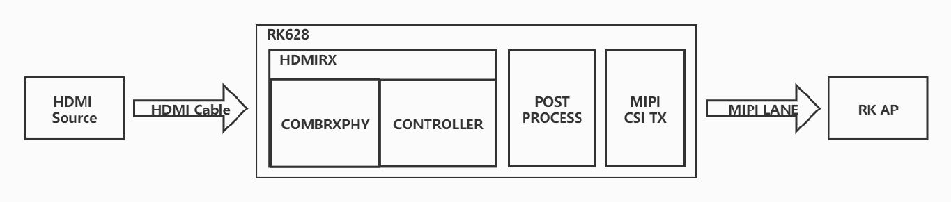
RK AP and RK628D block diagram — Chinese PDF p. 4
RK628D is an MFD device with an MFD driver and drivers for individual interface modules. RK628D HDMI RX to MIPI CSI TX is used for HDMI IN: RK628D is treated as a camera-like device, with drivers implemented in the V4L2 framework. Because this differs from the display DRM framework, only the COMBRXPHY and COMBTXPHY drivers are reused; HDMI RX Controller, Post Process and MIPI CSI TX are reimplemented within V4L2.
Related driver code:
drivers/mfd/rk628.c


drivers/gpu/drm/rockchip/rk628/rk628_combrxphy.c

drivers/gpu/drm/rockchip/rk628/rk628_combtxphy.c

drivers/media/i2c/rk628_csi.c
Kernel configuration:
CONFIG_MFD_RK628=y

CONFIG_VIDEO_RK628_CSI=y


CONFIG_DRM_ROCKCHIP_RK628=y
1.2 Implementing HDMI IN with other bridge chips
Other bridge chips do not use an MFD driver; they implement I2C device drivers directly in the V4L2 framework. Examples include TC358743, TC358749 and LT6911UXC.
Related driver code:
drivers/media/i2c/tc35874x.c


drivers/media/i2c/lt6911uxc.c
Kernel configuration:
CONFIG_VIDEO_TC35874X=y

CONFIG_VIDEO_LT6911UXC=y
2. HDMI IN video framework
The HDMI IN video implementation presents RK628D as a MIPI SoC camera device. Video data is received through the camera framework and displayed by the APK. HDMI IN hot-plug handling and automatic adaptation to the input resolution are added to meet HDMI IN application requirements.
2.1 HDMI IN APK workflow
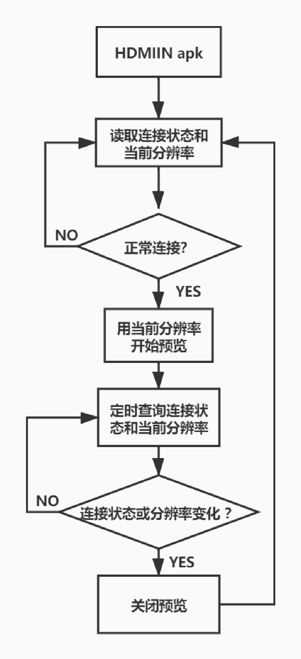
APK workflow — Chinese PDF p. 6
2.2 RK628D driver architecture
The RK628D driver has three main areas requiring attention: initialization, hot-plug interrupt handling, and resolution-change interrupt handling. Refer to the following flowcharts.
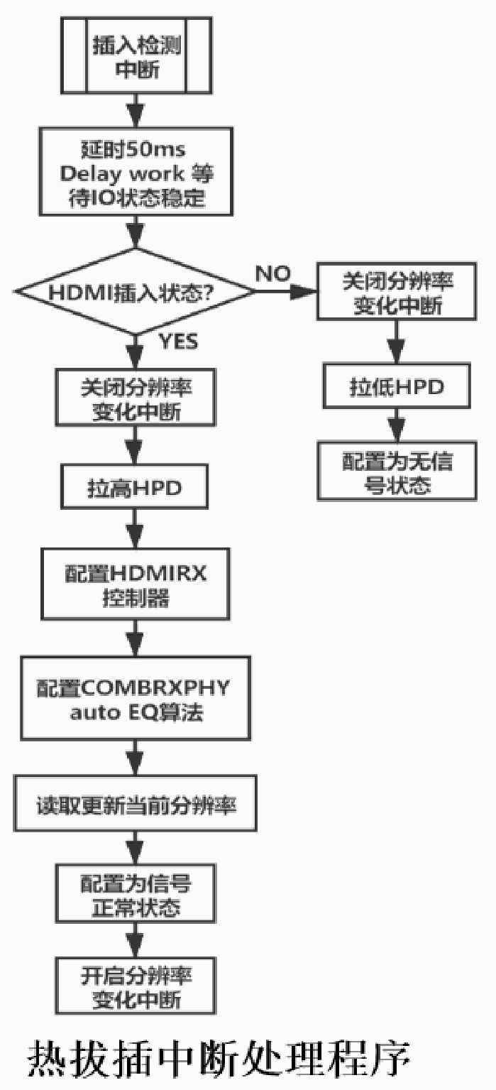
Driver hotplug flow — Chinese PDF p. 8
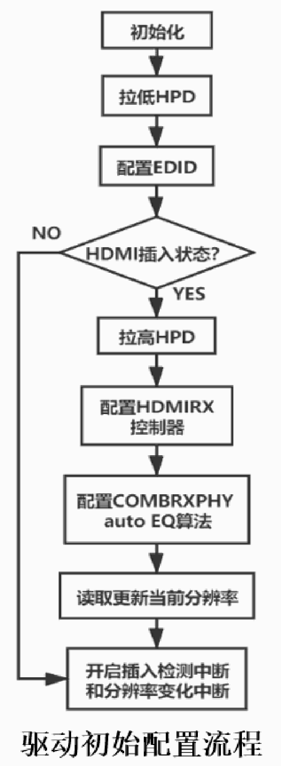
Driver initialization flow — Chinese PDF p. 8
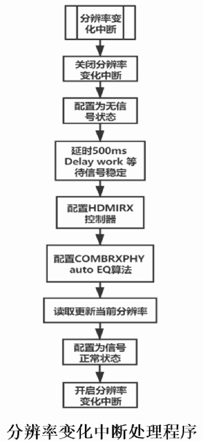
Resolution-change flow — Chinese PDF p. 9
3. Configuration
HDMI IN requires upgrading the SDK to at least the specified version and adjusting the board configuration to match the actual hardware connections.
3.1 SDK code requirements
Note: commit IDs may differ.
The kernel/ code must contain the following commits:
git log drivers/gpu/drm/rockchip/rk628/
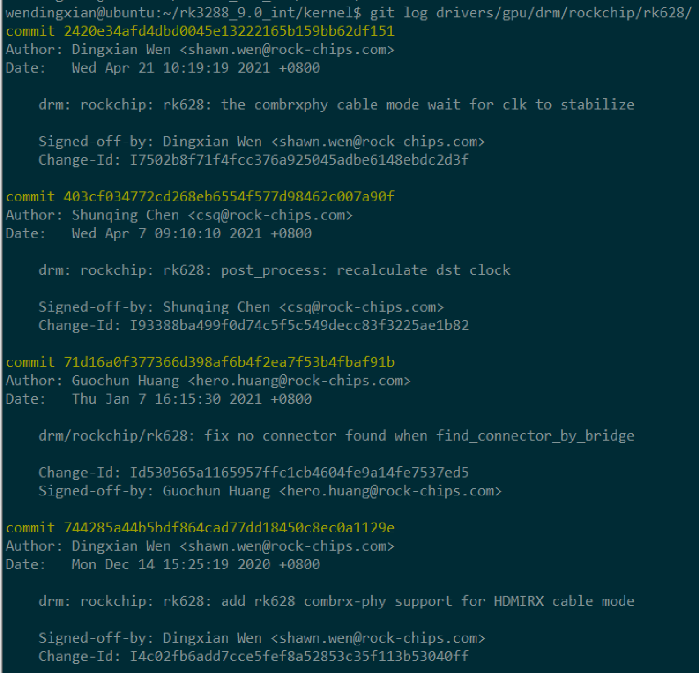
RK628 DRM commit history — Chinese PDF p. 10
Transcription of visible screenshot code (the source is a partial screenshot; cropped content is not invented):
wendingxian@ubuntu:~/rk3288_9.0_int/kernel$ git log drivers/gpu/drm/rockchip/rk628/
commit 2420e34afd4dbd0045e13222165b159bb62df151
Author: Dingxian Wen <shawn.wen@rock-chips.com>
Date:   Wed Apr 21 10:19:19 2021 +0800

    drm: rockchip: rk628: the combrxphy cable mode wait for clk to stabilize

    Signed-off-by: Dingxian Wen <shawn.wen@rock-chips.com>
    Change-Id: I7502b8f71f4fcc376a925045adbe6148ebdc2d3f

commit 403cf034772cd268eb6554f577d98462c007a90f
Author: Shunqing Chen <csq@rock-chips.com>
Date:   Wed Apr 7 09:10:10 2021 +0800

    drm: rockchip: rk628: post_process: recalculate dst clock

    Signed-off-by: Shunqing Chen <csq@rock-chips.com>
    Change-Id: I93388ba499f0d74c5f5c549decc83f3225ae1b82

commit 71d16a0f377366d398af6b4f2ea7f53b4fbaf91b
Author: Guochun Huang <hero.huang@rock-chips.com>
Date:   Thu Jan 7 16:15:30 2021 +0800

    drm/rockchip/rk628: fix no_connector found when find_connector_by_bridge

    Change-Id: Id530565a1165957ffc1cb4604fe9a14fe7537ed5
    Signed-off-by: Guochun Huang <hero.huang@rock-chips.com>

commit 744285a44b5bdf864cad77dd18450c8ec0a1129e
Author: Dingxian Wen <shawn.wen@rock-chips.com>
Date:   Mon Dec 14 15:25:19 2020 +0800

    drm: rockchip: rk628: add rk628 combrx-phy support for HDMIRX cable mode

    Signed-off-by: Dingxian Wen <shawn.wen@rock-chips.com>
    Change-Id: I4c02fb6add7cce5fef8a52853c35f113b53040ff
git log drivers/media/i2c/rk628_csi.c
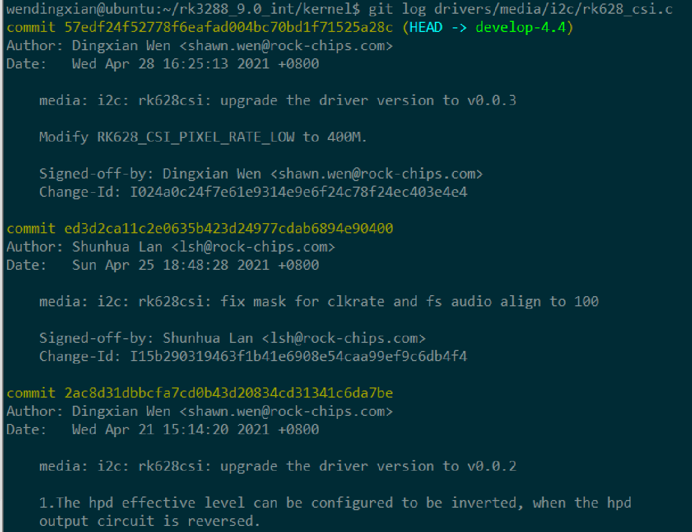
RK628 CSI driver commits — Chinese PDF p. 11
Transcription of visible screenshot code (the source is a partial screenshot; cropped content is not invented):
wendingxian@ubuntu:~/rk3288_9.0_int/kernel$ git log drivers/media/i2c/rk628_csi.c
commit 57edf24f52778f6eafad004bc70bd1f71525a28c (HEAD -> develop-4.4)
Author: Dingxian Wen <shawn.wen@rock-chips.com>
Date:   Wed Apr 28 16:25:13 2021 +0800

    media: i2c: rk628csi: upgrade the driver version to v0.0.3

    Modify RK628_CSI_PIXEL_RATE_LOW to 400M.

    Signed-off-by: Dingxian Wen <shawn.wen@rock-chips.com>
    Change-Id: I024a0c24f7e61e9314e9e6f24c78f24ec403e4e4

commit ed3d2ca11c2e0635b423d24977cdab6894e90400
Author: Shunhua Lan <lsh@rock-chips.com>
Date:   Sun Apr 25 18:48:28 2021 +0800

    media: i2c: rk628csi: fix mask for clkrate and fs audio align to 100

    Signed-off-by: Shunhua Lan <lsh@rock-chips.com>
    Change-Id: I15b290319463f1b41e6908e54caa99ef9c6db4f4

commit 2ac8d31dbbcfa7cd0b43d20834cd31341c6da7be
Author: Dingxian Wen <shawn.wen@rock-chips.com>
Date:   Wed Apr 21 15:14:20 2021 +0800

    media: i2c: rk628csi: upgrade the driver version to v0.0.2

    1.The hpd effective level can be configured to be inverted, when the hpd
    output circuit is reversed.
The hardware/rockchip/camera/ code must contain the following commit:
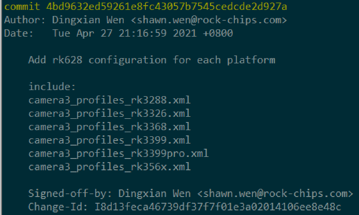
CameraHAL configuration commit — Chinese PDF p. 11
Transcription of visible screenshot code (the source is a partial screenshot; cropped content is not invented):
commit 4bd9632ed59261e8fc43057b7545cedcde2d927a
Author: Dingxian Wen <shawn.wen@rock-chips.com>
Date:   Tue Apr 27 21:16:59 2021 +0800

    Add rk628 configuration for each platform

    include:
    camera3_profiles_rk3288.xml
    camera3_profiles_rk3326.xml
    camera3_profiles_rk3368.xml
    camera3_profiles_rk3399.xml
    camera3_profiles_rk3399pro.xml
    camera3_profiles_rk356x.xml

    Signed-off-by: Dingxian Wen <shawn.wen@rock-chips.com>
    Change-Id: I8d13feca46739df37f7f01e3a02014106ee8e48c
The device/rockchip/common/ code must contain the following commit:
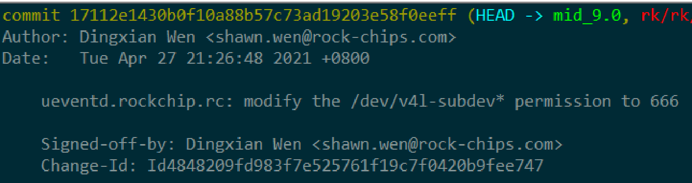
Device-permission commit — Chinese PDF p. 11
Transcription of visible screenshot code (the source is a partial screenshot; cropped content is not invented):
commit 17112e1430b0f10a88b57c73ad19203e58f0eeff (HEAD -> mid_9.0, rk/rk
Author: Dingxian Wen <shawn.wen@rock-chips.com>
Date:   Tue Apr 27 21:26:48 2021 +0800

    ueventd.rockchip.rc: modify the /dev/v4l-subdev* permission to 666

    Signed-off-by: Dingxian Wen <shawn.wen@rock-chips.com>
    Change-Id: Id4848209fd983f7e525761f19c7f0420b9fee747
The RKDocs/common/ code must contain the following commit:
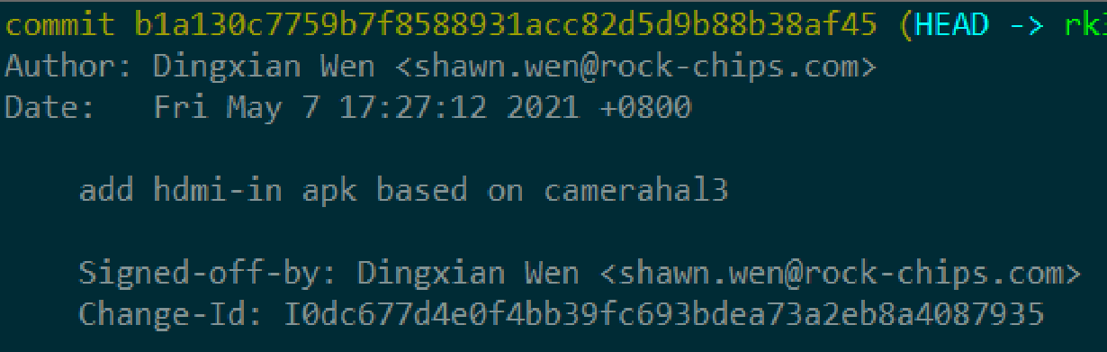
RKDocs APK commit — Chinese PDF p. 12
Transcription of visible screenshot code (the source is a partial screenshot; cropped content is not invented):
commit b1a130c7759b7f8588931acc82d5d9b88b38af45 (HEAD -> rk
Author: Dingxian Wen <shawn.wen@rock-chips.com>
Date:   Fri May 7 17:27:12 2021 +0800

    add hdmi-in apk based on camerahal3

    Signed-off-by: Dingxian Wen <shawn.wen@rock-chips.com>
    Change-Id: I0dc677d4e0f4bb39fc693bdea73a2eb8a4087935
3.2 Board configuration
The SDK includes a DTS configuration for the RK3288 RK628D EVB. Use the following file as a reference:
arch/arm/boot/dts/rk3288-evb-rk628-hdmi2csi-avb.dts
3.2.1 Functional modules
RK628D HDMI IN requires COMBRXPHY, COMBTXPHY and CSI, so enable these modules individually in DTS. Leave other unmentioned modules at their rk628.dtsi defaults; they do not need to be enabled. In particular, rk628_post_process, rk628_hdmi and rk628_hdmirx belong to RK628D display paths and must not be enabled for this HDMI IN setup.
&rk628_combrxphy {
      status = "okay";
};


&rk628_combtxphy {
      status = "okay";
};

&rk628_csi {
      status = "okay";
...
3.2.2 Hardware connections
RK628D is an I2C device and must be placed under the corresponding I2C bus. The main connection settings are shown below:
&i2c1 {
      clock-frequency = <400000>;
      status = "okay";


      rk628: rk628@50 {
           reg = <0x50>;
           interrupt-parent = <&gpio7>;
           interrupts = <15 IRQ_TYPE_LEVEL_HIGH>;
           enable-gpios = <&gpio5 RK_PC2 GPIO_ACTIVE_HIGH>;
           reset-gpios = <&gpio7 RK_PB6 GPIO_ACTIVE_LOW>;
           status = "okay";
      };
};
reg: I2C address. The typical 7-bit RK628D address is 0x50. When using multiple RK628D devices, GPIO strapping can change their I2C addresses, as shown below:
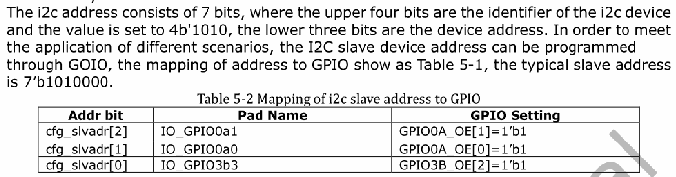
I2C slave-address GPIO mapping — Chinese PDF p. 13
The I2C address has 7 bits: the upper four identify the device (4b’1010), and the lower three form the device address and can be programmed through GPIO. The typical slave address is 7’b1010000. The image text cites Table 5-1, but its caption says Table 5-2; the original mapping is retained.
| Addr bit | Pad Name | GPIO Setting |
|---|---|---|
| cfg_slvadr[2] | IO_GPIO0a1 | GPIO0A_OE[1]=1’b1 |
| cfg_slvadr[1] | IO_GPIO0a0 | GPIO0A_OE[0]=1’b1 |
| cfg_slvadr[0] | IO_GPIO3b3 | GPIO3B_OE[2]=1’b1 |
interrupt-parent / interrupts: GPIO connected to the RK628D interrupt signal.
enable-gpios: RK628D power-control GPIO; it may be omitted if power is always supplied.
reset-gpios: RK628D reset-control GPIO.
The RK628_CSI module also requires hardware-connection settings, as follows:
&rk628_csi {
      status = "okay";
      /*

      * If the hpd output level is inverted on the circuit,
      * the following configuration needs to be enabled.
      */
      /* hpd-output-inverted; */
      plugin-det-gpios = <&gpio0 13 GPIO_ACTIVE_HIGH>;
      power-gpios = <&gpio0 17 GPIO_ACTIVE_HIGH>;
...
hpd-output-inverted: inverts the HPD output. Enable this option if the circuit inverts the HPD output level.
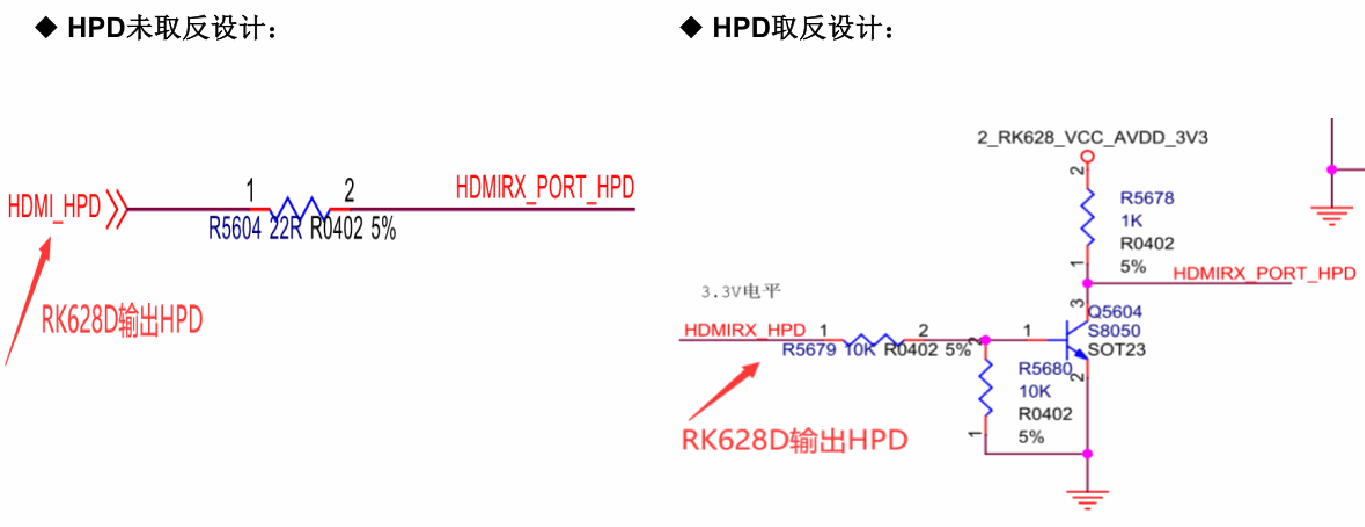
HPD circuit — Chinese PDF p. 14
plugin-det-gpios: HDMI plug-detection GPIO. Check whether the circuit inverts the level and configure the active level correctly.
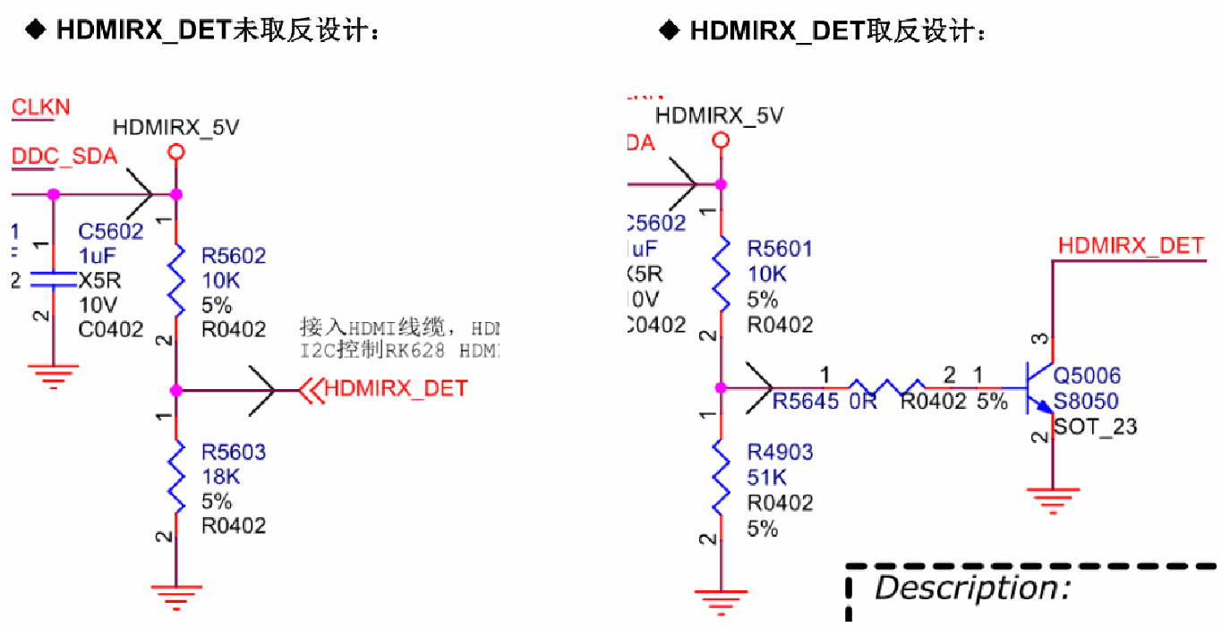
Insertion-detection circuit — Chinese PDF p. 14
power-gpios: power-control GPIO for the MIPI RX power domain on the Rockchip host; it may be omitted if power is always supplied.
3.2.3 DTS configuration of the image-reception pipeline
Treat RK628D, TC35874x, LT6911 and similar bridges as camera-like devices. Like camera sensors, they require a V4L2-based driver. Configure the data pipeline in the same way as a MIPI SoC sensor.
RK3288 example: rk628 + isp1 pipeline:
&rk628_csi {
   status = "okay";
   /*

   * If the hpd output level is inverted on the circuit,
   * the following configuration needs to be enabled.
   */
   /* hpd-output-inverted; */
   plugin-det-gpios = <&gpio0 13 GPIO_ACTIVE_HIGH>;
   power-gpios = <&gpio0 17 GPIO_ACTIVE_HIGH>;
   rockchip,camera-module-index = <0>;
   rockchip,camera-module-facing = "back";
   rockchip,camera-module-name = "RK628-CSI";
   rockchip,camera-module-lens-name = "NC";

   port {

      hdmiin_out0: endpoint {
         remote-endpoint = <&mipi_in>;
         data-lanes = <1 2 3 4>;
      };
   };
};

&mipi_phy_rx0 {
   status = "okay";

   ports {
      #address-cells = <1>;

      #size-cells = <0>;

      port@0 {
         reg = <0>;
         #address-cells = <1>;
         #size-cells = <0>;

         mipi_in: endpoint@1 {
            reg = <1>;
            remote-endpoint = <&hdmiin_out0>;
            data-lanes = <1 2 3 4>;
         };
      };


      port@1 {
         reg = <1>;
         #address-cells = <1>;
         #size-cells = <0>;

         dphy_rx_out: endpoint@0 {
            reg = <0>;
            remote-endpoint = <&isp_mipi_in>;
         };
      };
   };

};

&rkisp1 {
   status = "okay";
   port {
      #address-cells = <1>;
      #size-cells = <0>;

      isp_mipi_in: endpoint@0 {
         reg = <0>;
         remote-endpoint = <&dphy_rx_out>;
      };
   };

};

&isp_mmu {
   rockchip,camera-module-lens-name = "NC";

   port {

      hdmiin_out0: endpoint {
         remote-endpoint = <&mipi_in>;
         data-lanes = <1 2 3 4>;
      };
   };
};

&mipi_phy_rx0 {
   status = "okay";

   ports {
      #address-cells = <1>;

      #size-cells = <0>;

      port@0 {
         reg = <0>;
         #address-cells = <1>;
         #size-cells = <0>;

         mipi_in: endpoint@1 {
           reg = <1>;
           remote-endpoint = <&hdmiin_out0>;
           data-lanes = <1 2 3 4>;
         };
      };


      port@1 {
         reg = <1>;
         #address-cells = <1>;
         #size-cells = <0>;

         dphy_rx_out: endpoint@0 {
           reg = <0>;
           remote-endpoint = <&isp_mipi_in>;
         };
      };
   };

};

&rkisp1 {
   status = "okay";
   port {
      #address-cells = <1>;
      #size-cells = <0>;

      isp_mipi_in: endpoint@0 {
         reg = <0>;
         remote-endpoint = <&dphy_rx_out>;
      };
   };

};

&isp_mmu {
   status = "okay";
};
RK356x example: rk628 + isp2 pipeline:
&rk628_csi {
   status = "okay";

   /*
   * If the hpd output level is inverted on the circuit,
   * the following configuration needs to be enabled.
   */
   /* hpd-output-inverted; */
   plugin-det-gpios = <&gpio0 13 GPIO_ACTIVE_HIGH>;
   power-gpios = <&gpio0 17 GPIO_ACTIVE_HIGH>;
   rockchip,camera-module-index = <0>;
   rockchip,camera-module-facing = "back";
   rockchip,camera-module-name = "RK628-CSI";
   rockchip,camera-module-lens-name = "NC";

   port {

      hdmiin_out0: endpoint {
         remote-endpoint = <&mipi_in>;
         data-lanes = <1 2 3 4>;
      };
   };
};

&csi2_dphy_hw {
   status = "okay";
};

&csi2_dphy0 {

   status = "okay";

   ports {
      #address-cells = <1>;
      #size-cells = <0>;
      port@0 {
         reg = <0>;
         #address-cells = <1>;
         #size-cells = <0>;

         mipi_in: endpoint@0 {
           reg = <0>;
           remote-endpoint = <&hdmiin_out0>;

           data-lanes = <1 2 3 4>;
         };
      };
      port@1 {
         reg = <1>;
         #address-cells = <1>;
         #size-cells = <0>;

         csidphy0_out: endpoint@0 {
           reg = <0>;
           remote-endpoint = <&isp0_in>;
         };
      };

   };
};

&rkisp {
   status = "okay";
};

&rkisp_mmu {
   status = "okay";
};

&rkisp_vir0 {

   status = "okay";

   port {
      #address-cells = <1>;
      #size-cells = <0>;

      isp0_in: endpoint@0 {
         reg = <0>;
         remote-endpoint = <&csidphy0_out>;
      };
   };
};
RK356x example: rk628 + vicap pipeline:
&rk628_csi {
   status = "okay";

   /*
   * If the hpd output level is inverted on the circuit,
   * the following configuration needs to be enabled.
   */
   /* hpd-output-inverted; */
   plugin-det-gpios = <&gpio0 13 GPIO_ACTIVE_HIGH>;
   power-gpios = <&gpio0 17 GPIO_ACTIVE_HIGH>;
   rockchip,camera-module-index = <0>;
   rockchip,camera-module-facing = "back";
   rockchip,camera-module-name = "RK628-CSI";
   rockchip,camera-module-lens-name = "NC";

   port {

      hdmiin_out0: endpoint {
         remote-endpoint = <&mipi_in>;
         data-lanes = <1 2 3 4>;
      };
   };
};

&csi2_dphy_hw {
   status = "okay";
};
&csi2_dphy0 {
   status = "okay";


   ports {
      #address-cells = <1>;
      #size-cells = <0>;
      port@0 {
         reg = <0>;
         #address-cells = <1>;
         #size-cells = <0>;

         mipi_in: endpoint@0 {
            reg = <0>;
            remote-endpoint = <&hdmiin_out0>;

            data-lanes = <1 2 3 4>;
         };
      };
      port@1 {
         reg = <1>;
         #address-cells = <1>;
         #size-cells = <0>;

         csidphy0_out: endpoint@0 {
            reg = <0>;
            remote-endpoint = <&mipi_csi2_input>;
            data-lanes = <1 2 3 4>;
         };

      };
   };
};

&mipi_csi2 {
   status = "okay";

   ports {
      #address-cells = <1>;
      #size-cells = <0>;

      port@0 {

         reg = <0>;
         #address-cells = <1>;
         #size-cells = <0>;

         mipi_csi2_input: endpoint@1 {
            reg = <1>;
            remote-endpoint = <&csidphy0_out>;
            data-lanes = <1 2 3 4>;
         };
      };

      port@1 {
         reg = <1>;

         #address-cells = <1>;
         #size-cells = <0>;
&csi2_dphy0 {
   status = "okay";


   ports {
      #address-cells = <1>;
      #size-cells = <0>;
      port@0 {
         reg = <0>;
         #address-cells = <1>;
         #size-cells = <0>;

         mipi_in: endpoint@0 {
           reg = <0>;
           remote-endpoint = <&hdmiin_out0>;

           data-lanes = <1 2 3 4>;
         };
      };
      port@1 {
         reg = <1>;
         #address-cells = <1>;
         #size-cells = <0>;

         csidphy0_out: endpoint@0 {
           reg = <0>;
           remote-endpoint = <&mipi_csi2_input>;
           data-lanes = <1 2 3 4>;
         };

      };
   };
};

&mipi_csi2 {
   status = "okay";

   ports {
      #address-cells = <1>;
      #size-cells = <0>;

      port@0 {

         reg = <0>;
         #address-cells = <1>;
         #size-cells = <0>;

         mipi_csi2_input: endpoint@1 {
           reg = <1>;
           remote-endpoint = <&csidphy0_out>;
           data-lanes = <1 2 3 4>;
         };
      };

      port@1 {
         reg = <1>;

         #address-cells = <1>;
         #size-cells = <0>;
         mipi_csi2_output: endpoint@0 {
           reg = <0>;
           remote-endpoint = <&cif_mipi_in>;

           data-lanes = <1 2 3 4>;
         };
      };
   };
};

&rkcif {
   status = "okay";
};

&rkcif_mipi_lvds {
   status = "okay";


   port {
      cif_mipi_in: endpoint {
         remote-endpoint = <&mipi_csi2_output>;
         data-lanes = <1 2 3 4>;
      };
   };
};

&rkcif_mmu {
   status = "okay";
};
3.3 camera3_profiles.xml configuration
camera3_profiles.xml corresponds to the platform-specific file in the SDK:
hardware/rockchip/camera/etc/camera/camera3_profiles_rk3xxx.xml
The main configuration considerations are listed below. Refer to the SoC sensor configuration procedure for details.
name: must match the driver name and is case-sensitive.
moduleId: must match the index configured in the driver’s DTS.

Camera profile XML — Chinese PDF p. 19
Transcription of visible screenshot code (the source is a partial screenshot; cropped content is not invented):
</Profiles>
<Profiles cameraId="0" name="rk628-csi" moduleId="m00">
    <Supported_hardware>
        <hwType value="SUPPORTED_HW_RKISP1"/>
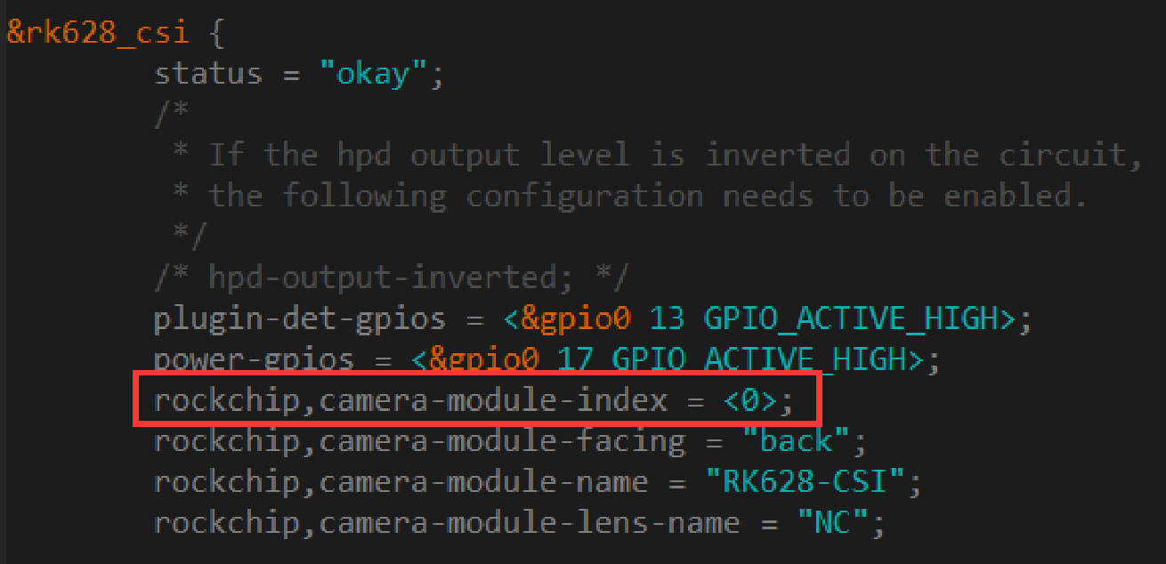
DTS module index — Chinese PDF p. 20
Transcription of visible screenshot code (the source is a partial screenshot; cropped content is not invented):
&rk628_csi {
    status = "okay";
    /*
     * If the hpd output level is inverted on the circuit,
     * the following configuration needs to be enabled.
     */
    /* hpd-output-inverted; */
    plugin-det-gpios = <&gpio0 13 GPIO_ACTIVE_HIGH>;
    power-gpios = <&gpio0 17 GPIO_ACTIVE_HIGH>;
    rockchip,camera-module-index = <0>;
    rockchip,camera-module-facing = "back";
    rockchip,camera-module-name = "RK628-CSI";
    rockchip,camera-module-lens-name = "NC";
scaler.availableStreamConfigurations / scaler.availableMinFrameDurations / scaler.availableStallDurations: correctly configure the resolutions supported by the driver and the minimum frame intervals. When adding a new resolution to the driver, add its configuration here as well.
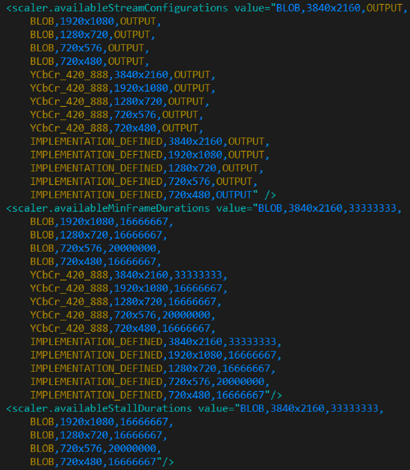
XML resolutions and frame durations — Chinese PDF p. 20
Transcription of visible screenshot code (the source is a partial screenshot; cropped content is not invented):
<scaler.availableStreamConfigurations value="BLOB,3840x2160,OUTPUT,
    BLOB,1920x1080,OUTPUT,
    BLOB,1280x720,OUTPUT,
    BLOB,720x576,OUTPUT,
    BLOB,720x480,OUTPUT,
    YCbCr_420_888,3840x2160,OUTPUT,
    YCbCr_420_888,1920x1080,OUTPUT,
    YCbCr_420_888,1280x720,OUTPUT,
    YCbCr_420_888,720x576,OUTPUT,
    YCbCr_420_888,720x480,OUTPUT,
    IMPLEMENTATION_DEFINED,3840x2160,OUTPUT,
    IMPLEMENTATION_DEFINED,1920x1080,OUTPUT,
    IMPLEMENTATION_DEFINED,1280x720,OUTPUT,
    IMPLEMENTATION_DEFINED,720x576,OUTPUT,
    IMPLEMENTATION_DEFINED,720x480,OUTPUT" />
<scaler.availableMinFrameDurations value="BLOB,3840x2160,33333333,
    BLOB,1920x1080,16666667,
    BLOB,1280x720,16666667,
    BLOB,720x576,20000000,
    BLOB,720x480,16666667,
    YCbCr_420_888,3840x2160,33333333,
    YCbCr_420_888,1920x1080,16666667,
    YCbCr_420_888,1280x720,16666667,
    YCbCr_420_888,720x576,20000000,
    YCbCr_420_888,720x480,16666667,
    IMPLEMENTATION_DEFINED,3840x2160,33333333,
    IMPLEMENTATION_DEFINED,1920x1080,16666667,
    IMPLEMENTATION_DEFINED,1280x720,16666667,
    IMPLEMENTATION_DEFINED,720x576,20000000,
    IMPLEMENTATION_DEFINED,720x480,16666667"/>
<scaler.availableStallDurations value="BLOB,3840x2160,33333333,
    BLOB,1920x1080,16666667,
    BLOB,1280x720,16666667,
    BLOB,720x576,20000000,
    BLOB,720x480,16666667"/>
sensor.orientation: image rotation angle; supported values are 0, 90, 180 and 270.

Sensor orientation XML — Chinese PDF p. 21
Transcription of visible screenshot code (the source is a partial screenshot; cropped content is not invented):
<sensor.maxAnalogSensitivity value="2400"/>
<sensor.orientation value="0"/>
<sensor.profileHueSatMapDimensions value="0,0,0"/>
3.4 Reception capabilities of different platforms
Maximum image-reception capabilities differ because ISP/VICAP performance varies across platforms. Refer to the following source table:
| Chip platform | Receiver | Maximum supported resolution |
|---|---|---|
| RK3288/RK3326/RK3368 | isp | 1920x1080P60 |
| RK3399 | isp | 3840x2160P30 (ISP overclocking required) |
| RK3566/RK3568 | vicap/isp | 3840x2160P30 |
3.4.1 Configuring ISP overclocking on RK3399
Configure PLL_NPLL to 650M:
--- a/arch/arm64/boot/dts/rockchip/rk3399-vop-clk-set.dtsi
+++ b/arch/arm64/boot/dts/rockchip/rk3399-vop-clk-set.dtsi

@@ -148,7 +148,7 @@
                  <50000000>, <100000000>,
                  <75000000>, <75000000>,
                  <816000000>, <816000000>,
-                 <600000000>, <200000000>,
+                 <650000000>, <200000000>,
                  <800000000>, <150000000>,
                  <75000000>, <37500000>,
                  <300000000>, <100000000>,
Change the maximum supported RK3399 ISP frequency to 650M:
--- a/drivers/media/platform/rockchip/isp1/dev.c
+++ b/drivers/media/platform/rockchip/isp1/dev.c
@@ -757,7 +757,7 @@ static const unsigned int rk3368_isp_clk_rate[] = {


 /* isp clock adjustment table (MHz) */
 static const unsigned int rk3399_isp_clk_rate[] = {
-     300, 400, 600
+     300, 400, 650
 };

 static struct isp_irqs_data rk1808_isp_irqs[] = {
Configure the ISP frequency in the bridge-chip driver:
#define RK628_CSI_PIXEL_RATE_HIGH 600000000
...


static int rk628_csi_set_fmt(struct v4l2_subdev *sd,
           struct v4l2_subdev_pad_config *cfg,
           struct v4l2_subdev_format *format)
{
...
      if ((mode->width == 3840) && (mode->height == 2160)) {
           v4l2_dbg(1, debug, sd,
                 "%s res wxh:%dx%d, link freq:%llu, pixrate:%u\n",
                 __func__, mode->width, mode->height,
                 link_freq_menu_items[1], RK628_CSI_PIXEL_RATE_HIGH);
           __v4l2_ctrl_s_ctrl(csi->link_freq, 1);
           __v4l2_ctrl_s_ctrl_int64(csi->pixel_rate,

                 RK628_CSI_PIXEL_RATE_HIGH);
      }
...
}
The ISP driver adds a further 25% margin to the configured frequency, so set an appropriate RK628_CSI_PIXEL_RATE_HIGH value in the driver.
drivers/media/platform/rockchip/isp1/dev.c


static int __isp_pipeline_s_isp_clk(struct rkisp1_pipeline *p)
{
...
      ctrl = v4l2_ctrl_find(sd->ctrl_handler, V4L2_CID_PIXEL_RATE);
      if (!ctrl) {
           v4l2_warn(sd, "No pixel rate control in subdev\n");
           return -EPIPE;
      }

      /* calculate data rate */
      data_rate = v4l2_ctrl_g_ctrl_int64(ctrl) *
              dev->isp_sdev.in_fmt.bus_width;
      data_rate >>= 3;

      do_div(data_rate, 1000 * 1000);

      /* increase 25% margin */
      data_rate += data_rate >> 2;
...
}
3.4.2 Configuring ISP to use CMA memory
When receiving HDMI IN images on some platforms, the actual system load can cause insufficient bandwidth, resulting in dropped frames or abnormal MIPI reception. An example error log follows:
[ 228.999567] rkisp1: MIPI mis error: 0x00800000
[ 228.999925] rkisp1: CIF_ISP_PIC_SIZE_ERROR (0x00000001)
[ 228.999976] rkisp1: CIF_ISP_PIC_SIZE_ERROR (0x00000001)rkisp1:

CIF_ISP_PIC_SIZE_ERROR (0x00000001)
[ 229.000081] rkisp1: CIF_ISP_PIC_SIZE_ERROR (0x00000001)rkisp1:
CIF_ISP_PIC_SIZE_ERROR (0x00000001)
[ 229.000187] rkisp1: CIF_ISP_PIC_SIZE_ERROR (0x00000001)rkisp1:
CIF_ISP_PIC_SIZE_ERROR (0x00000001)
[ 229.000294] rkisp1: CIF_ISP_PIC_SIZE_ERROR (0x00000001)rkisp1:
CIF_ISP_PIC_SIZE_ERROR (0x00000001)
Increase the DDR frequency in this case. If that does not help, reserve CMA memory for the ISP to mitigate the problem:
Reserve 128 MB of CMA memory in rockchip_defconfig:
CONFIG_CMA=y
CONFIG_CMA_SIZE_MBYTES=128
Disable the ISP IOMMU in DTS so that the ISP uses CMA memory:
&isp_mmu {
      status = "disabled";

};
3.5 EDID configuration
RK628D supports configurable EDID. The EDID in the source driver supports the following resolutions:
3840x2160P30, 1920x1080P60, 1920x1080P30, 1280x720P60, 720x576P50, 720x480P60.
To change the supported resolutions, edit the EDID directly in the driver code:
drivers/media/i2c/rk628_csi.c

static u8 edid_init_data[] = {

      0x00, 0xFF, 0xFF, 0xFF, 0xFF, 0xFF, 0xFF, 0x00,
      0x52, 0x62, 0x01, 0x88, 0x00, 0x88, 0x88, 0x88,
      0x1C, 0x15, 0x01, 0x03, 0x80, 0x00, 0x00, 0x78,
      0x0A, 0x0D, 0xC9, 0xA0, 0x57, 0x47, 0x98, 0x27,
      0x12, 0x48, 0x4C, 0x00, 0x00, 0x00, 0x01, 0x01,
      0x01, 0x01, 0x01, 0x01, 0x01, 0x01, 0x01, 0x01,
      0x01, 0x01, 0x01, 0x01, 0x01, 0x01, 0x02, 0x3A,
      0x80, 0x18, 0x71, 0x38, 0x2D, 0x40, 0x58, 0x2C,
      0x45, 0x00, 0xC4, 0x8E, 0x21, 0x00, 0x00, 0x1E,
      0x01, 0x1D, 0x00, 0x72, 0x51, 0xD0, 0x1E, 0x20,
      0x6E, 0x28, 0x55, 0x00, 0xC4, 0x8E, 0x21, 0x00,
      0x00, 0x1E, 0x00, 0x00, 0x00, 0xFC, 0x00, 0x54,
      0x37, 0x34, 0x39, 0x2D, 0x66, 0x48, 0x44, 0x37,

      0x32, 0x30, 0x0A, 0x20, 0x00, 0x00, 0x00, 0xFD,
      0x00, 0x14, 0x78, 0x01, 0xFF, 0x1D, 0x00, 0x0A,
      0x20, 0x20, 0x20, 0x20, 0x20, 0x20, 0x01, 0x7B,

      0x02, 0x03, 0x1A, 0x71, 0x47, 0x5F, 0x90, 0x22,
   0x04, 0x11, 0x02, 0x01, 0x23, 0x09, 0x07, 0x01,
...
4. Adapting the HDMI IN APK
4.1 Obtaining and compiling the APK source
The APK source is provided in the SDK directory:
RKDocs/common/hdmi-in/apk/rkCamera2_based_on_CameraHal3_V1.3.tar.gz
Copy and extract the source into:
packages/apps/
For RK3288, make changes similar to the following in device/rockchip/rk3288/ to include the rkCamera2 APK in the build:
diff --git a/device.mk b/device.mk
index 6667b5c..96f08f1 100644
--- a/device.mk

+++ b/device.mk
@@ -17,7 +17,8 @@
 PRODUCT_PACKAGES += \
   memtrack.$(TARGET_BOARD_PLATFORM) \
   WallpaperPicker \
-  Launcher3
+  Launcher3 \
+  rkCamera2

 #$_rbox_$_modify_$_zhengyang: add displayd
 PRODUCT_PACKAGES += \
4.2 Adapting the APK source
The APK accesses the RK628D device node using ioctl to obtain the current connection state and resolution. The RK628D device node can differ between isp1, isp2 and vicap pipelines. Update the APK source for the actual setup. The debugging-command examples explain how to identify the node.
rkCamera2/jni/native.cpp
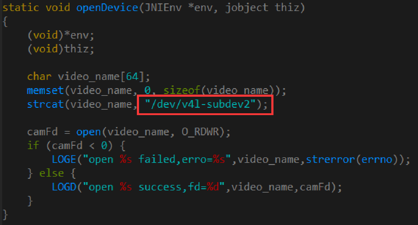
C++ device-open example — Chinese PDF p. 25
Transcription of visible screenshot code (the source is a partial screenshot; cropped content is not invented):
static void openDevice(JNIEnv *env, jobject thiz)
{
    (void)*env;
    (void)thiz;

    char video_name[64];
    memset(video_name, 0, sizeof(video_name));
    strcat(video_name, "/dev/v4l-subdev2");

    camFd = open(video_name, O_RDWR);
    if (camFd < 0) {
        LOGE("open %s failed,erro=%s",video_name,strerror(errno));
    } else {
        LOGD("open %s success,fd=%d",video_name,camFd);
    }
}
The code for retrieving the current connection state and resolution is shown below:
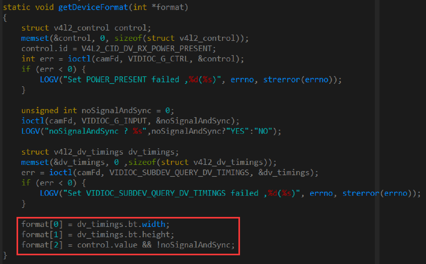
C++ signal/format query — Chinese PDF p. 25
Transcription of visible screenshot code (the source is a partial screenshot; cropped content is not invented):
static void getDeviceFormat(int *format)
{
    struct v4l2_control control;
    memset(&control, 0, sizeof(struct v4l2_control));
    control.id = V4L2_CID_DV_RX_POWER_PRESENT;
    int err = ioctl(camFd, VIDIOC_G_CTRL, &control);
    if (err < 0) {
        LOGV("Set POWER_PRESENT failed ,%d(%s)", errno, strerror(errno));
    }

    unsigned int noSignalAndSync = 0;
    ioctl(camFd, VIDIOC_G_INPUT, &noSignalAndSync);
    LOGV("noSignalAndSync ? %s",noSignalAndSync?"YES":"NO");

    struct v4l2_dv_timings dv_timings;
    memset(&dv_timings, 0, sizeof(struct v4l2_dv_timings));
    err = ioctl(camFd, VIDIOC_SUBDEV_QUERY_DV_TIMINGS, &dv_timings);
    if (err < 0) {
        LOGV("Set VIDIOC_SUBDEV_QUERY_DV_TIMINGS failed ,%d(%s)", errno, strerror(errno));
    }

    format[0] = dv_timings.bt.width;
    format[1] = dv_timings.bt.height;
    format[2] = control.value && !noSignalAndSync;
}
Because the APK accesses a device node, the source asks to check whether SELinux is disabled, using getenforce. The screenshot demonstrates switching to permissive mode. This is a source debugging procedure, not a recommendation to disable protection in production.
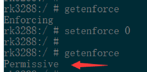
SELinux debugging example — Chinese PDF p. 25
Transcription of visible screenshot code (the source is a partial screenshot; cropped content is not invented):
rk3288:/ # getenforce
Enforcing
rk3288:/ # setenforce 0
rk3288:/ #
rk3288:/ # getenforce
Permissive
4.3 Preparation before APK debugging
First complete driver debugging, as described in the driver-debugging section. Then verify that the camera device is correctly registered with CameraHal using the following command. If registration is incorrect, inspect camera3_profiles.xml as described in its configuration section.
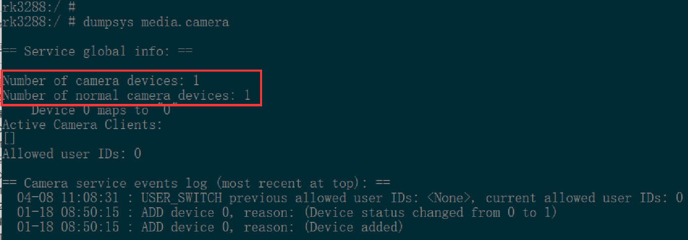
Camera service status — Chinese PDF p. 26
Transcription of visible screenshot code (the source is a partial screenshot; cropped content is not invented):
rk3288:/ #
rk3288:/ # dumpsys media.camera

== Service global info: ==

Number of camera devices: 1
Number of normal camera devices: 1
    Device 0 maps to "0"
Active Camera Clients:
[]
Allowed user IDs: 0

== Camera service events log (most recent at top): ==
  04-08 11:08:31 : USER_SWITCH previous allowed user IDs: <None>, current allowed user IDs: 0
  01-18 08:50:15 : ADD device 0, reason: (Device status changed from 0 to 1)
  01-18 08:50:15 : ADD device 0, reason: (Device added)
5. Driver debugging
Debug the driver as for a SoC sensor. The source refers to the following Redmine document for further information:
https://redmine.rock-chips.com/documents/53
5.1 Obtaining debugging tools
The media-ctl and v4l2-ctl tools are required. The SDK described in the source automatically copies them into the firmware during compilation; they are stored under:
hardware/rockchip/camera/etc/tools/
For older SDK versions, obtain them from Redmine:
https://redmine.rock-chips.com/documents/104
Use adb push to copy media-ctl and v4l2-ctl into /vendor/bin/ on the device.
5.2 Debugging-command examples
The following example uses RK3288 + RK628D to receive 1920x1080P. Adjust the commands to match the actual setup.
Inspect the pipeline topology:
Run the command to inspect the media-node topology. Depending on the platform and pipeline, the node may be /dev/media0 or /dev/media1.
media-ctl -d /dev/media0 –p
The RK628D excerpt below identifies its device as /dev/v4l-subdev2 and the detected HDMI IN resolution as 1920x1080.
...
- entity 8: m00_b_rk628-csi rk628-csi (1 pad, 1 link)
         type V4L2 subdev subtype Sensor

         device node name /dev/v4l-subdev2
      pad0: Source
           [fmt:UYVY2X8/1920x1080]
           -> "rockchip-mipi-dphy-rx":0 [ENABLED]
...
Configure pipeline links:
After reset and boot, the links are enabled by default. Opening and then exiting the HDMI IN APK disconnects them. Reconnect only when [ENABLED] is absent from the topology output.
media-ctl -d /dev/media0 -l \
'"m00_b_rk628-csi rk628-csi":0->"rockchip-mipi-dphy-rx":0 [1]'

media-ctl -d /dev/media0 -l \
'"rockchip-mipi-dphy-rx":1->"rkisp1-isp-subdev":0 [1]'
media-ctl -d /dev/media0 -l '"rkisp1-input-params":0->"rkisp1-isp-subdev":1 [1]'
media-ctl -d /dev/media0 -l '"rkisp1-isp-subdev":2->"rkisp1_mainpath":0 [1]'
media-ctl -d /dev/media0 -l '"rkisp1-isp-subdev":2->"rkisp1_selfpath":0 [1]'
media-ctl -d /dev/media0 -l '"rkisp1-isp-subdev":3->"rkisp1-statistics":0 [1]'
Configure resolution:
media-ctl -d /dev/media0 \
--set-v4l2 '"rkisp1-isp-subdev":0[fmt:UYVY2X8/1920x1080]'
media-ctl -d /dev/media0 \

--set-v4l2 '"rkisp1-isp-subdev":0[crop:(0,0)/1920x1080]'
media-ctl -d /dev/media0 \
--set-v4l2 '"rkisp1-isp-subdev":2[fmt:UYVY2X8/1920x1080]'
media-ctl -d /dev/media0 \
--set-v4l2 '"rkisp1-isp-subdev":2[crop:(0,0)/1920x1080]'
Acquire the image stream:
Inspect the resulting configuration:
media-ctl -d /dev/media0 –p
Acquire the image stream:
v4l2-ctl --verbose -d /dev/video0 \
--set-fmt-video=width=1920,height=1080,pixelformat='NV12' \
--stream-mmap=4 \

--set-selection=target=crop,flags=0,top=0,left=0,width=1920,height=1080
Capture a YUV image file; use adb pull to retrieve it and inspect it with a tool such as 7yuv:
v4l2-ctl --verbose -d /dev/video0 \
--set-fmt-video=width=1920,height=1080,pixelformat='NV12' \
--stream-mmap=4 --stream-skip=5 --stream-count=10 \

--stream-to=/data/rk628_1920x1080.yuv --stream-poll
If reception works normally, the output reports the frame rate. Example log:
VIDIOC_QUERYCAP: ok
VIDIOC_G_FMT: ok
VIDIOC_S_FMT: ok

Format Video Capture Multiplanar:
      Width/Height : 1920/1080
      Pixel Format : 'NV12'
      Field        : None
      Number of planes : 1
      Flags        :
      Colorspace   : Default
      Transfer Function : Default
      YCbCr Encoding : Default
      Quantization : Full Range
      Plane 0      :
        Bytes per Line : 1920
        Size Image : 3110400

VIDIOC_G_SELECTION: ok
VIDIOC_S_SELECTION: ok
VIDIOC_REQBUFS: ok
VIDIOC_QUERYBUF: ok
VIDIOC_QUERYBUF: ok
VIDIOC_QBUF: ok
VIDIOC_QUERYBUF: ok
VIDIOC_QBUF: ok
VIDIOC_QUERYBUF: ok
VIDIOC_QBUF: ok
VIDIOC_QUERYBUF: ok
VIDIOC_QBUF: ok

VIDIOC_STREAMON: ok
idx: 0 seq: 0 bytesused: 3110400 ts: 131.560377
idx: 1 seq: 1 bytesused: 3110400 ts: 131.577023 delta: 16.646 ms
idx: 2 seq: 2 bytesused: 3110400 ts: 131.593697 delta: 16.674 ms
idx: 3 seq: 3 bytesused: 3110400 ts: 131.610363 delta: 16.666 ms
idx: 0 seq: 4 bytesused: 3110400 ts: 131.627033 delta: 16.670 ms fps: 60.01
idx: 1 seq: 5 bytesused: 3110400 ts: 131.643721 delta: 16.688 ms fps: 59.99
idx: 2 seq: 6 bytesused: 3110400 ts: 131.660390 delta: 16.669 ms fps: 59.99
idx: 3 seq: 7 bytesused: 3110400 ts: 131.677058 delta: 16.668 ms fps: 59.99
6. Troubleshooting
6.1 Enabling logging
Enable RK628D logging with the following command, then obtain the kernel log. The source spells the log command demsg; verify dmesg on the target system.
echo 1 > /sys/module/rk628_csi/parameters/debug
To capture logs from power-on and boot, the source recommends modifying the code and rebuilding and flashing the relevant kernel components:
diff --git a/drivers/media/i2c/rk628_csi.c b/drivers/media/i2c/rk628_csi.c
index c763a9558169..bd7f3effb45a 100644
--- a/drivers/media/i2c/rk628_csi.c

+++ b/drivers/media/i2c/rk628_csi.c
@@ -34,7 +34,7 @@
 #include <video/videomode.h>
 #include "rk628_csi.h"

-static int debug;
+static int debug = 1;
 module_param(debug, int, 0644);
 MODULE_PARM_DESC(debug, "debug level (0-3)");

diff --git a/include/media/v4l2-common.h b/include/media/v4l2-common.h
index 1cc0c5ba16b3..e74f3a85f0b8 100644

--- a/include/media/v4l2-common.h
+++ b/include/media/v4l2-common.h
@@ -75,7 +75,7 @@
 #define v4l2_dbg(level, debug, dev, fmt, arg...)   \
      do {                                          \
           if (debug >= (level))                    \
-                v4l2_printk(KERN_DEBUG, dev, fmt , ## arg); \
+                v4l2_printk(KERN_INFO, dev, fmt , ## arg); \
      } while (0)
6.2 Reading and writing registers
RK628 register-debug nodes are shown below. In this example RK628 is connected to I2C1 at address 0x51.
rk3288:/ # ls -l /d/regmap/
total 0
drwxr-xr-x 2 root root 0 1970-01-01 00:00 0-001b

drwxr-xr-x 2 root root 0 1970-01-01 00:00 1-0051-combrxphy
drwxr-xr-x 2 root root 0 1970-01-01 00:00 1-0051-combtxphy
drwxr-xr-x 2 root root 0 1970-01-01 00:00 1-0051-cru
drwxr-xr-x 2 root root 0 1970-01-01 00:00 1-0051-csi
drwxr-xr-x 2 root root 0 1970-01-01 00:00 1-0051-grf
drwxr-xr-x 2 root root 0 1970-01-01 00:00 1-0051-hdmirx
drwxr-xr-x 2 root root 0 1970-01-01 00:00 1-0051-key_map
drwxr-xr-x 2 root root 0 1970-01-01 00:00 1-0051-rk628-pinctrl
drwxr-xr-x 2 root root 0 1970-01-01 00:00 2-001a
drwxr-xr-x 2 root root 0 1970-01-01 00:00 ff890000.i2s

drwxr-xr-x 2 root root 0 1970-01-01 00:00 ff96c000.video-phy
Register nodes are read-only by default. To enable register writes, the source gives the following change:
diff --git a/drivers/base/regmap/regmap-debugfs.c b/drivers/base/regmap/regmap-
debugfs.c
index 3f0a7e262d69..b819645edd84 100644

--- a/drivers/base/regmap/regmap-debugfs.c
+++ b/drivers/base/regmap/regmap-debugfs.c
@@ -259,7 +259,7 @@ static ssize_t regmap_map_read_file(struct file *file, char
__user *user_buf,
                         count, ppos);
 }

-#undef REGMAP_ALLOW_WRITE_DEBUGFS
+#define REGMAP_ALLOW_WRITE_DEBUGFS
 #ifdef REGMAP_ALLOW_WRITE_DEBUGFS
 /*
 * This can be dangerous especially when we have clients such as
Read registers:
rk3288:/ # cat /d/regmap/1-0051-cru/registers
c0000: 00001063

c0004: 00001442
c0008: 00000000
c000c: 00000007
c0010: 00007f00
c0020: 00006010
c0024: 00000581
c0028: 00ef348b
c002c: 00000007
c0030: 00007f00
...
Write a register:
rk3288:/ # echo 0x000 0xffffffff > /d/regmap/1-0051-grf/registers
6.3 MFD device errors
RK628D is an MFD device. Immediately after power-on, child devices such as COMBRXPHY can fail to probe with -517 because the parent has not finished probing. They are probed again, so these initial errors are harmless if the deferred probe subsequently succeeds.
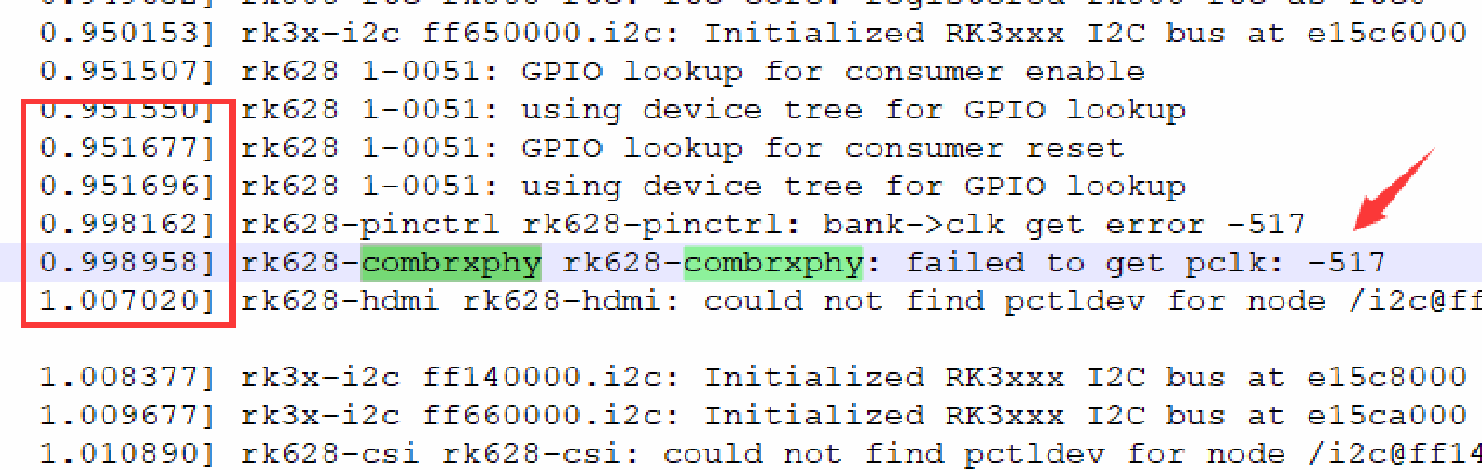
MFD probe log — Chinese PDF p. 31
Transcription of visible screenshot code (the source is a partial screenshot; cropped content is not invented):
0.950153] rk3x-i2c ff650000.i2c: Initialized RK3xxx I2C bus at e15c6000
0.951507] rk628 1-0051: GPIO lookup for consumer enable
0.951550] rk628 1-0051: using device tree for GPIO lookup
0.951677] rk628 1-0051: GPIO lookup for consumer reset
0.951696] rk628 1-0051: using device tree for GPIO lookup
0.998162] rk628-pinctrl rk628-pinctrl: bank->clk get error -517
0.998958] rk628-combrxphy rk628-combrxphy: failed to get pclk: -517
1.007020] rk628-hdmi rk628-hdmi: could not find pctldev for node /i2c@ff

1.008377] rk3x-i2c ff140000.i2c: Initialized RK3xxx I2C bus at e15c8000
1.009677] rk3x-i2c ff660000.i2c: Initialized RK3xxx I2C bus at e15ca000
1.010690] rk628-csi rk628-csi: could not find pctldev for node /i2c@ff14
6.4 Clk det errors
If COMBRXPHY does not detect a signal, an incorrect HDMI plug-detection or HPD active level may prevent the source from outputting HDMI normally. Check plugin-det-gpios and hpd-output-inverted under rk628_csi; the HPD level can also be measured with a multimeter.
Errors trigger retries, up to retry 2. If operation becomes normal after retrying, the source considers the signal normal.
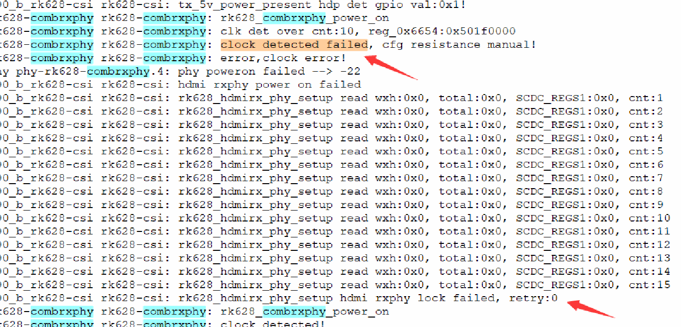
Clock-detection retry log — Chinese PDF p. 31
Transcription of visible screenshot code (the source is a partial screenshot; cropped content is not invented):
0_b_rk628-csi rk628-csi: tx_5v_power_present hdp det gpio val:0x1!
628-combrxphy rk628-combrxphy: rk628_combrxphy_power_on
628-combrxphy rk628-combrxphy: clk det over cnt:10, reg_0x6654:0x501f000
628-combrxphy rk628-combrxphy: clock detected failed, cfg resistance manual!
628-combrxphy rk628-combrxphy: error,clock error!
hy phy-rk628-combrxphy.4: phy poweron failed --> -22
0_b_rk628-csi rk628-csi: hdmi rxphy power on failed
0_b_rk628-csi rk628-csi: rk628_hdmirx_phy_setup read wxh:0x0, total:0x0, SCDC_REGS1:0x0, cnt:1
0_b_rk628-csi rk628-csi: rk628_hdmirx_phy_setup read wxh:0x0, total:0x0, SCDC_REGS1:0x0, cnt:2
0_b_rk628-csi rk628-csi: rk628_hdmirx_phy_setup read wxh:0x0, total:0x0, SCDC_REGS1:0x0, cnt:3
0_b_rk628-csi rk628-csi: rk628_hdmirx_phy_setup read wxh:0x0, total:0x0, SCDC_REGS1:0x0, cnt:4
0_b_rk628-csi rk628-csi: rk628_hdmirx_phy_setup read wxh:0x0, total:0x0, SCDC_REGS1:0x0, cnt:5
0_b_rk628-csi rk628-csi: rk628_hdmirx_phy_setup read wxh:0x0, total:0x0, SCDC_REGS1:0x0, cnt:6
0_b_rk628-csi rk628-csi: rk628_hdmirx_phy_setup read wxh:0x0, total:0x0, SCDC_REGS1:0x0, cnt:7
0_b_rk628-csi rk628-csi: rk628_hdmirx_phy_setup read wxh:0x0, total:0x0, SCDC_REGS1:0x0, cnt:8
0_b_rk628-csi rk628-csi: rk628_hdmirx_phy_setup read wxh:0x0, total:0x0, SCDC_REGS1:0x0, cnt:9
0_b_rk628-csi rk628-csi: rk628_hdmirx_phy_setup read wxh:0x0, total:0x0, SCDC_REGS1:0x0, cnt:10
0_b_rk628-csi rk628-csi: rk628_hdmirx_phy_setup read wxh:0x0, total:0x0, SCDC_REGS1:0x0, cnt:11
0_b_rk628-csi rk628-csi: rk628_hdmirx_phy_setup read wxh:0x0, total:0x0, SCDC_REGS1:0x0, cnt:12
0_b_rk628-csi rk628-csi: rk628_hdmirx_phy_setup read wxh:0x0, total:0x0, SCDC_REGS1:0x0, cnt:13
0_b_rk628-csi rk628-csi: rk628_hdmirx_phy_setup read wxh:0x0, total:0x0, SCDC_REGS1:0x0, cnt:14
0_b_rk628-csi rk628-csi: rk628_hdmirx_phy_setup read wxh:0x0, total:0x0, SCDC_REGS1:0x0, cnt:15
0_b_rk628-csi rk628-csi: rk628_hdmirx_phy_setup hdmi rxphy lock failed, retry:0
628-combrxphy rk628-combrxphy: rk628_combrxphy_power_on
628-combrxphy rk628-combrxphy: clock detected!
6.5 Determining whether HDMI RX works normally
Once COMBRXPHY locks normally, the HDMI RX controller can parse the timings. These timings are calculated, so small discrepancies, commonly one unit, may occur. Refer to the CEA standard documents for detailed timing definitions.

Normal HDMI timing log — Chinese PDF p. 31
Transcription of visible screenshot code (the source is a partial screenshot; cropped content is not invented):
m00_b_rk628-csi rk628-csi: cnt_num:1000, tmds_cnt:3000, hs_cnt:15, vs_cnt:3667, hofs:192
m00_b_rk628-csi rk628-csi: SCDC_REGS1:0xffff0f00, act:1920x1080, total:2200x1125, fps:60,
m00_b_rk628-csi rk628-csi: hfp:88, hs:45, hbp:147, vfp:4, vs:5, vbp:36, interlace:0
m00_b_rk628-csi rk628-csi: rk628-csi_s_dv_timings: 1920x1080p60.0 (2200x1125)
m00_b_rk628-csi rk628-csi: enable_stream: disable
6.6 Open-subdevice permission errors

Device-permission error log — Chinese PDF p. 32
Transcription of visible screenshot code (the source is a partial screenshot; cropped content is not invented):
D JNI     : JNI CAMERA CALL init
I HdmiInput-native: JNI OnLoad
I HdmiInput-native: Apk Version: V1.2
E HdmiInput-native: openDevice(91): open /dev/v4l-subdev2 failed,erro=Permission denied
D RockchipCamera2: remove take pic button
D RockchipCamera2: recreatTextureview
D RockchipCamera2: textureView remove
D RockchipCamera2: onResume
Check whether /dev/v4l-subdev* has the 666 permissions specified by the source. Query from the device shell:
rk3288:/ # cat /vendor/ueventd.rc | grep subdev
/dev/v4l-subdev*   0666 media   camera
The SDK described in the source already includes this commit. If it is absent, use the following change in device/rockchip/common/ as a reference. Broad device permissions require a security review before production use.
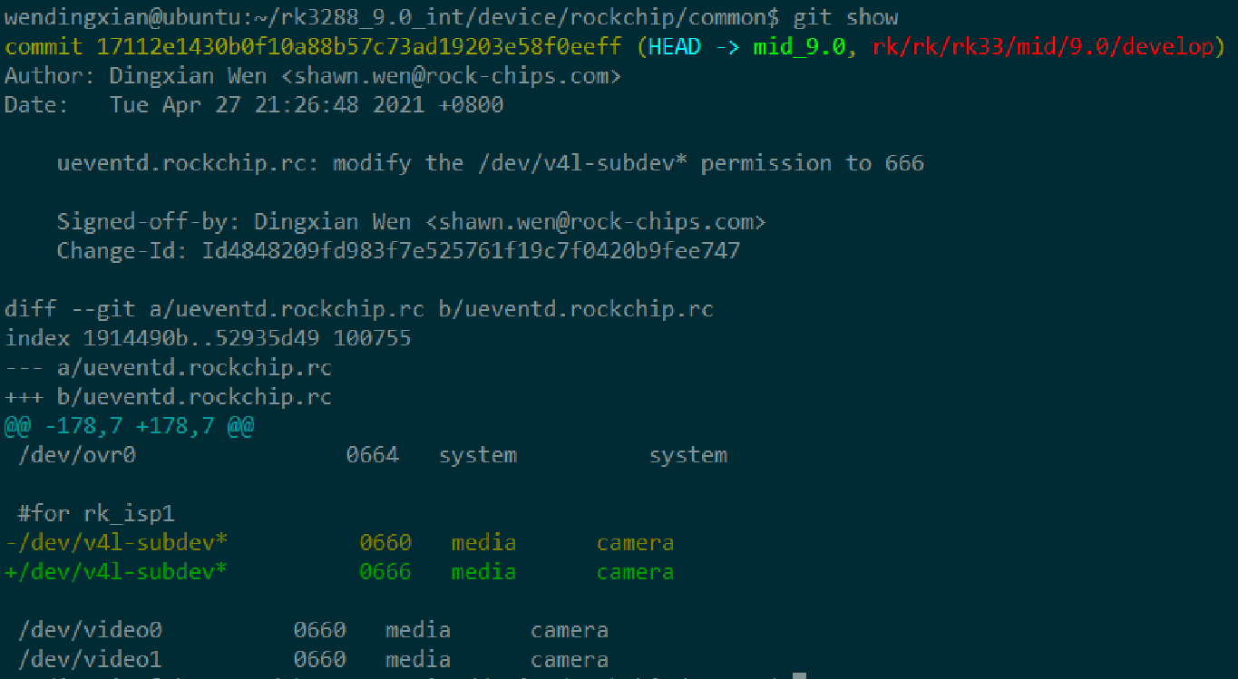
ueventd permission patch — Chinese PDF p. 32
Transcription of visible screenshot code (the source is a partial screenshot; cropped content is not invented):
wendingxian@ubuntu:~/rk3288_9.0_int/device/rockchip/common$ git show
commit 17112e1430b0f10a88b57c73ad19203e58f0eeff (HEAD -> mid_9.0, rk/rk/rk33/mid/9.0/develop)
Author: Dingxian Wen <shawn.wen@rock-chips.com>
Date:   Tue Apr 27 21:26:48 2021 +0800

    ueventd.rockchip.rc: modify the /dev/v4l-subdev* permission to 666

    Signed-off-by: Dingxian Wen <shawn.wen@rock-chips.com>
    Change-Id: Id4848209fd983f7e525761f19c7f0420b9fee747

diff --git a/ueventd.rockchip.rc b/ueventd.rockchip.rc
index 1914490b..52935d49 100755
--- a/ueventd.rockchip.rc
+++ b/ueventd.rockchip.rc
@@ -178,7 +178,7 @@
 /dev/ovr0                0664   system     system

 #for rk_isp1
-/dev/v4l-subdev*         0660   media      camera
+/dev/v4l-subdev*         0666   media      camera

 /dev/video0         0660   media      camera
 /dev/video1         0660   media      camera