
四语以中文V1.2.0(19页)为主线,补齐英文V1.1.1(21页)独有说明。原稿范围:非RK3576示例对应Linux4.4/4.19,RK3576对应Linux6.1;中文新增3.2.2、3.3.2完整保留。作为ArmSoM平台参考,需核对具体板卡/SoC、BSP、PMIC接线和散热设计;没有验证所有板卡或这些温度阈值的安全性。中文图取中文PDF,英俄德图取英文PDF,均为软件架构原图。全部计算为原稿示例,未作硬件测试。
原稿疑点保留:中文路径power_allocator.缺c,英文为power_allocator.c;RK3576示例仍标A53/A72,且threshold=75却在算式写85−70,结果1353mW与列出的式子不一致;RK3399静态功耗t_scale的中间算式与778250结果也需核对。所有原值保留,不能直接用作产品热设计。关闭温控仅保留为原文调试方法,不建议用于正常运行;本次未执行相关命令。
1. 概述
Thermal 是内核开发者定义的一套支持根据指定 governor 控制系统温度,以防止芯片过热的框架模型。Thermal framework 由 governor、core、cooling device、sensor driver 组成,软件架构如下:
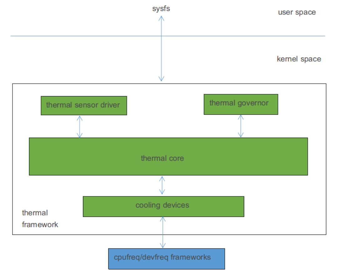
Thermal软件架构(中文原图)
Thermal governor决定cooling device是否降频及降频程度。原稿列出Linux4.4策略:
- power_allocator:PID控制,按当前温度动态分配power,并转换为频率限制。
- step_wise:按温度逐级降频。
- fair share:档位较多的cooling device优先降频。
- userspace:中文写“不限制频率”;英文补充“只向用户态通知温控事件”。
Thermal core封装抽象governor与driver并定义接口。Thermal sensor driver获取温度,例如tsadc。Thermal cooling device为发热源或降温设备,例如CPU、GPU、DDR。
2. 代码路径
Governor 相关代码:
drivers/thermal/power_allocator.    /* power allocator温控策略 */
drivers/thermal/step_wise.c         /* step wise温控策略 */
drivers/thermal/fair_share.c        /* fair share温控策略 */
drivers/thermal/user_space.c        /* userspace温控策略 */
Cooling device 相关代码:
drivers/thermal/devfreq_cooling.c
drivers/thermal/cpu_cooling.c
Core 相关代码:
drivers/thermal/thermal_core.c
Driver 相关代码:
drivers/thermal/rockchip_thermal.c    /* 除了RK3368外的其他平台的tsadc驱动 */
drivers/thermal/rk3368_thermal.c      /* RK3368平台tsadc驱动 */
3. 配置方法
3.1 Menuconfig 配置
<*> Generic Thermal sysfs driver  --->
    --- Generic Thermal sysfs driver
    [*]   APIs to parse thermal data out of device tree
    [*]   Enable writable trip points
        Default Thermal governor (power_allocator)  --->    /* default thermal
governor */
    [ ]   Fair-share thermal governor
    [ ]   Step_wise thermal governor                            /* step_wise
governor */
    [ ]   Bang Bang thermal governor
    [*]   User_space thermal governor                           /* user_space
governor */
    -*-   Power allocator thermal governor                      /*
power_allocator governor */
    [*]   generic cpu cooling support                           /* cooling device
*/
    [ ]   Generic clock cooling support
    [*]   Generic device cooling support                        /* cooling device
*/
    [ ]   Thermal emulation mode support
    < >   Temperature sensor driver for Freescale i.MX SoCs
    <*>   Rockchip thermal driver                               /* thermal sensor
driver */
    < >     rk_virtual thermal driver
    <*>     rk3368 thermal driver legacy                        /* thermal sensor
driver */
通过“Default Thermal governor”配置项,可以选择温控策略,开发者可以根据实际产品需求进行修改。
3.2 Tsadc 配置
3.2.1 示例配置
Tsadc 在温控中作为 thermal sensor,用于获取温度,通常需要在 DTSI 和 DTS 都做配置。以 RK3399 为例,DTSI 包括如下配置:
tsadc: tsadc@ff260000 {
    compatible = "rockchip,rk3399-tsadc";
    reg = <0x0 0xff260000 0x0 0x100>;                   /* 寄存器基地址和寄存器地址总
⻓度 */
    interrupts = <GIC_SPI 97 IRQ_TYPE_LEVEL_HIGH 0>;    /* 中断号及中断触发方式 */
    assigned-clocks = <&cru SCLK_TSADC>;                /* 工作时钟,750KHz */
    assigned-clock-rates = <750000>;
    clocks = <&cru SCLK_TSADC>, <&cru PCLK_TSADC>;      /* 工作时钟和配置时钟 */
    clock-names = "tsadc", "apb_pclk";
    resets = <&cru SRST_TSADC>;                         /* 复位信号 */
    reset-names = "tsadc-apb";
    rockchip,grf = <&grf>;                              /* 引用grf模块,部分平台需要
*/
    rockchip,hw-tshut-temp = <120000>;                  /* 过温重启阈值,120摄氏度 */
    /* tsadc输出引脚配置,支持两种模式:gpio和otpout */
    pinctrl-names = "gpio", "otpout";
    pinctrl-0 = <&otp_gpio>;
    pinctrl-1 = <&otp_out>;
    /*
     * thermal sensor标识,表示tsadc可以作为一个thermal sensor,
     * 并指定了引用tsadc节点的时候需要带几个参数。
     * 如果SoC里面只有一个tsadc,可以设置为0,超过一个必须设置为1。
     */
    #thermal-sensor-cells = <1>;
    status = "disabled";
};

/* IO口配置 */
pinctrl: pinctrl {
    ...
    tsadc {
        /* 配置为gpio模式 */
        otp_gpio: otp-gpio {
            rockchip,pins = <1 6 RK_FUNC_GPIO &pcfg_pull_none>;
        };
        /* 配置为over temperature protection模式 */
        otp_out: otp-out {
            rockchip,pins = <1 6 RK_FUNC_1 &pcfg_pull_none>;
        };
    };
    ....
}
DTS 的配置,主要用于选择通过 CRU 复位还是 GPIO 复位,低电平复位还是高电平复位。需要特别注意的是如果配置成 GPIO 复位,硬件上需要否把 tsadc 输出引脚连到 PMIC 的复位脚,否则只能配置成CRU 复位。
&tsadc {
    rockchip,hw-tshut-mode = <1>;        /* tshut mode 0:CRU 1:GPIO */
    rockchip,hw-tshut-polarity = <1>;    /* tshut polarity 0:LOW 1:HIGH */
    status = "okay";
};
参考文档”Documentation/devicetree/bindings/thermal/rockchip-thermal.txt”。
3.2.2 RK3576
tsadc: tsadc@2ae70000 {
    compatible = "rockchip,rk3576-tsadc";
    reg = <0x0 0x2ae70000 0x0 0x400>;                   /* 寄存器基地址和寄存器地址总
⻓度 */
    interrupts = <GIC_SPI 123 IRQ_TYPE_LEVEL_HIGH>;     /* 中断号及中断触发方式 */
    clocks = <&cru CLK_TSADC>, <&cru PCLK_TSADC>;       /* 工作时钟和配置时钟 */
    clock-names = "tsadc", "apb_pclk";
    assigned-clocks = <&cru CLK_TSADC>;                 /* 工作时钟,2MHz */
    assigned-clock-rates = <2000000>;
    resets = <&cru SRST_TSADC>, <&cru SRST_P_TSADC>;    /* 复位信号 */
    reset-names = "tsadc", "tsadc-apb";
    #thermal-sensor-cells = <1>;
    rockchip,hw-tshut-temp = <120000>;                  /* 过温重启阈值,120摄氏度 */
    rockchip,hw-tshut-mode = <0>;                       /* tshut mode 0:CRU
1:GPIO */
    rockchip,hw-tshut-polarity = <0>;                   /* tshut polarity 0:LOW
1:HIGH */
    status = "disabled";
};
rockchip,hw-tshut-mode配置为CRU时, 不需要有pinctrl-names, pinctrl-0和pinctrl-1这三个属性, 推荐将tshut-mode配置为CRU。若将tshut-mode配置为GPIO, 需要配置pinctrl-names, pinctrl-0和pinctrl-1:
tsadc: tsadc@2ae70000 {
    ...
    rockchip,hw-tshut-polarity = <1>;    /* tshut polarity 0:LOW 1:HIGH */
    pinctrl-names = "gpio", "otpout";
    pinctrl-0 = <&otp_gpio>;
    pinctrl-1 = <&tsadc_ctrl_pins>;
    status = "disabled";
};
/* rk3576-pinctrl.dtsi中需要有otp_gpio和tsadc_ctrl_pins */
&pinctrl {
    ...
    tsadc_ctrl {
        /omit-if-no-ref/
        otp_gpio: otp-gpio {
            rockchip,pins = <0 RK_PA1 RK_FUNC_GPIO &pcfg_pull_none>;
        };
        /omit-if-no-ref/
        tsadc_ctrl_pins: tsadc_ctrl-pins {
            rockchip,pins =
                /* tsadc_ctrl_org */
                <0 RK_PA1 10 &pcfg_pull_none>;
        };
    };
    ....
}
3.3 Power allocator 策略配置
Power allocator 温控策略引入 PID(比例-积分-微分)控制,根据当前温度,动态给各 cooling device分配 power,温度低的时候可分配的 power 比较大,即可以运行的频率高,随着温度上升,可分配的power 逐渐减小,可运行的频率也逐渐降低,从而达到根据温度限制频率。
3.3.1 示例配置
3.3.1.1 CPU 配置
CPU 在温控中作为 cooling device,节点中需要包含#cooling-cells、dynamic-power-coefficient 属性。以 RK3399 为例:
cpu_l0: cpu@0 {
    device_type = "cpu";
    compatible = "arm,cortex-a53", "arm,armv8";
    reg = <0x0 0x0>;
    enable-method = "psci";
    #cooling-cells = <2>;                 /* cooling device标识,表示该设备可以作为一
个cooling device */
    clocks = <&cru ARMCLKL>;
    cpu-idle-states = <&CPU_SLEEP &CLUSTER_SLEEP>;
    dynamic-power-coefficient = <100>;    /* 动态功耗常数C,动态功耗公式为Pdyn=C*V^2*F
*/
};
...
cpu_b0: cpu@100 {
    device_type = "cpu";
    compatible = "arm,cortex-a72", "arm,armv8";
    reg = <0x0 0x100>;
    enable-method = "psci";
    #cooling-cells = <2>;                 /* cooling device标识,表示该设备可以作为一
个cooling device */
    clocks = <&cru ARMCLKB>;
    cpu-idle-states = <&CPU_SLEEP &CLUSTER_SLEEP>;
    dynamic-power-coefficient = <436>;    /* 用于计算动态功耗的参数 */
};
3.3.1.2 GPU 配置
GPU 在温控中作为 cooling device,节点需要包含#cooling-cells 属性和 power_model 子节点。以 RK3399 为例:
gpu: gpu@ff9a0000 {
    compatible = "arm,malit860",
    "arm,malit86x",
    "arm,malit8xx",
    "arm,mali-midgard";

    reg = <0x0 0xff9a0000 0x0 0x10000>;

    interrupts = <GIC_SPI 19 IRQ_TYPE_LEVEL_HIGH 0>,
    <GIC_SPI 20 IRQ_TYPE_LEVEL_HIGH 0>,
    <GIC_SPI 21 IRQ_TYPE_LEVEL_HIGH 0>;
    interrupt-names = "GPU", "JOB", "MMU";

    clocks = <&cru ACLK_GPU>;
    clock-names = "clk_mali";
    #cooling-cells = <2>;                     /* cooling device标识,表示该设备可以作
为一个cooling device */
    power-domains = <&power RK3399_PD_GPU>;
    power-off-delay-ms = <200>;
    status = "disabled";

    gpu_power_model: power_model {
        compatible = "arm,mali-simple-power-model";
        static-coefficient = <411000>;    /* 用于计算静态功耗的参数 */
        dynamic-coefficient = <733>;      /* 用于计算动态功耗的参数 */
        ts = <32000 4700 (-80) 2>;        /* 用于计算静态功耗的参数 */
        thermal-zone = "gpu-thermal";     /* 从gpu-thermal获取温度,用于计算静态功耗
*/
    };
};
3.3.1.3 Thermal Zone 配置
Termal zone 节点主要用于配置温控策略相关的参数并生成对应的用戶态接口。以 RK3399 为例:
thermal_zones: thermal-zones {
    /* 一个节点对应一个thermal zone,并包含温控策略相关参数 */
    soc_thermal: soc-thermal {
        /* 温度高于trip-point-0指定的值,每隔20ms获取一次温度 */
        polling-delay-passive = <20>; /* milliseconds */
        /* 温度低于trip-point-0指定的值,每隔1000ms获取一次温度 */
        polling-delay = <1000>; /* milliseconds */
        /* 温度等于trip-point-1指定的值时,系统分配给cooling device的能量 */
        sustainable-power = <1000>; /* milliwatts */
        /* 当前thermal zone通过tsadc0获取温度 */
        thermal-sensors = <&tsadc 0>;

        /* trips包含不同温度阈值,不同的温控策略,配置不一定相同 */
        trips {
            /*
             * 温控阈值,超过该值温控策略开始工作,但不一定⻢上限制频率,
             * power小到一定程度才开始限制频率
             */
            threshold: trip-point-0 {
                /* 超过70摄氏度,温控策略开始工作,并且70摄氏度也是tsadc触发中断的一个阈值
*/
                temperature = <70000>; /* millicelsius */
                /* 温度低于temperature-hysteresis时触发中断,当前未实现,但是框架要求必须
填 */
                hysteresis = <2000>; /* millicelsius */
                type = "passive"; /* 表示超过该温度值时,使用polling-delay-passive */
            };
            /* 温控目标温度,期望通过降频使得芯片不超过该值 */
            target: trip-point-1 {
                /* 期望通过降频使得芯片不超过85摄氏度,并且85摄氏度也是tsadc触发中断的一个阈
值 */
                temperature = <85000>; /* millicelsius */
                /* 温度低于temperature-hysteresis时触发中断,当前未实现,但是框架要求必须
填 */
                hysteresis = <2000>; /* millicelsius */
                type = "passive"; /* 表示超过该温度值时,使用polling-delay-passive */
            };
            /* 过温保护阈值,如果降频后温度仍然上升,那么超过该值后,让系统重启 */
            soc_crit: soc-crit {
                /* 超过115摄氏度重启,并且115摄氏度也是tsadc触发中断的一个阈值  */
                temperature = <115000>; /* millicelsius */
                /* 温度低于temperature-hysteresis时触发中断,当前未实现,但是框架要求必须
填 */
                hysteresis = <2000>; /* millicelsius */
                type = "critical"; /* 表示超过该温度值时,重启 */
            };
        };

        /* cooling device配置节点,每个子节点代表一个cooling device */
        cooling-maps {
            map0 {
                /*
                 * 表示在target trip下,该cooling device才起作用,
                 * 对于power allocater策略必须填target
                 */
                trip = <&target>;
                /* A53做为cooloing device, THERMAL_NO_LIMIT不起作用,但必须填 */
                cooling-device =
                    <&cpu_l0 THERMAL_NO_LIMIT THERMAL_NO_LIMIT>;
                contribution = <4096>; /* 计算功耗时乘以4096/1024倍,用于调整降频顺序和
尺度 */
            };
            map1 {
                /*
                 * 表示在target trip下,该cooling device才起作用,
                 * 对于power allocater策略必须填target
                 */
                trip = <&target>;
                /* A72做为cooloing device, THERMAL_NO_LIMIT不起作用,但必须填 */
                cooling-device =
                    <&cpu_b0 THERMAL_NO_LIMIT THERMAL_NO_LIMIT>;
                contribution = <1024>;/* 计算功耗时乘以1024/1024倍,用于调整降频顺序和尺
度 */
            };
            map2 {
                /*
                 * 表示在target trip下,该cooling device才起作用,
                 * 对于power allocater策略必须填target
                 */
                trip = <&target>;
                /* GPU做为cooloing device, THERMAL_NO_LIMIT不起作用,但必须填 */
                cooling-device =
                    <&gpu THERMAL_NO_LIMIT THERMAL_NO_LIMIT>;
                contribution = <4096>;/* 计算功耗时乘以4096/1024倍,用于调整降频顺序和尺
度 */
            };
        };
    };
    /* 一个节点对应一个thermal zone,并包含温控策略相关参数,当前thermal zone只用于获取温度
*/
    gpu_thermal: gpu-thermal {
        /* 包含温控策略配置的情况下才起作用,架要求必须填 */
        polling-delay-passive = <100>; /* milliseconds */
        /* 每隔1000ms获取一次温度 */
        polling-delay = <1000>; /* milliseconds */

        /* 当前thermal zone通过tsadc1获取温度 */
        thermal-sensors = <&tsadc 1>;
    };
};
参考文档”Documentation/devicetree/bindings/thermal/thermal.txt”、”Documentation/thermal/power_allocator.txt”。
3.3.1.4 温控参数调整
有些参数是跟芯片相关,一般不需要修改。有些参数需要根据产品实际情况调整,通常情况可以按以下步骤进行:(1)确定目标温度。假设我们希望 70 度以上温控开始工作(更频繁地获取温度),最高温度不超过 85 度,超过 115 度系统重启。于是要做如下配置:
thermal_zones: thermal-zones {
    soc_thermal: soc-thermal {
        ....
        trips {
            threshold: trip-point-0 {
                /*
                 * 70度以上温控开始工作,缩短了获取温度的是时间间隔,但不一定⻢上降频,
                 * 还跟sustainable-power有关
                 */
                temperature = <70000>; /* millicelsius */
                hysteresis = <2000>; /* millicelsius */
                type = "passive";
            };
            target: trip-point-1 {
                /* 期望最高温度不超过85度 */
                temperature = <85000>; /* millicelsius */
                hysteresis = <2000>; /* millicelsius */
                type = "passive";
            };
            soc_crit: soc-crit {
                /* 超过115度系统重启 */
                temperature = <115000>; /* millicelsius */
                hysteresis = <2000>; /* millicelsius */
                type = "critical";
            };
        };
    ...
    }
};
(2)确定 cooling device。以 RK3399 为例,有些产品需要用到 CPU 和 GPU,可以做如下配置:
thermal_zones: thermal-zones {
    soc_thermal: soc-thermal {
        ...
        /* A53、A72、GPU三个模块都作为cooling device,可通过降频降温 */
        cooling-maps {
            map0 {
                trip = <&target>;
                cooling-device =
                    <&cpu_l0 THERMAL_NO_LIMIT THERMAL_NO_LIMIT>;
                contribution = <4096>;
            };
            map1 {
                trip = <&target>;
                cooling-device =
                    <&cpu_b0 THERMAL_NO_LIMIT THERMAL_NO_LIMIT>;
                contribution = <1024>;
            };
            map2 {
                trip = <&target>;
                cooling-device =
                    <&gpu THERMAL_NO_LIMIT THERMAL_NO_LIMIT>;
                contribution = <4096>;
            };
        };
    ...
    };
};
有些产品只用到 CPU,可以做如下配置:
thermal_zones: thermal-zones {
    soc_thermal: soc-thermal {
        ...
        /* 只有A53、A72两个模块作为cooling device,可通过降频降温 */
        cooling-maps {
            map0 {
                trip = <&target>;
                cooling-device =
                    <&cpu_l0 THERMAL_NO_LIMIT THERMAL_NO_LIMIT>;
                contribution = <4096>;
            };
            map1 {
                trip = <&target>;
                cooling-device =
                    <&cpu_b0 THERMAL_NO_LIMIT THERMAL_NO_LIMIT>;
                contribution = <1024>;
            };
        };
    ...
    };
};
(3)调整 sustainable-power。在(1)中设置了一个 70 度到 85 度的范围,表示系统在 70 度的时候会提供一个比较大的 power 值,随着温度的升高,power 逐渐减小,减到一定程度后开始降频,如果温度继续升高,power 继续降低,频率也继续降低。所以超过 70 度的时候只是获取温度的时间间隔缩短了,并不一定会降频,具体什么时候降频可以通过修改 sustainable 的值进行调整。假如我们设置为超过 70 度温控策略开始工作,即缩短获取温度的时间间隔,75 度的时候开始限制频率(这样设可以减小温控刚开始时频率波动的幅度),最高不超过 85 度。那么可以先让 75 度时的 power值等于所以 cooling device 的最大功耗之和,然后适当减小调试,直到满足我们的需求。功耗分为静态功耗和动态功耗,计算公式分别如下:
静态功耗公式:
    /* a、b、c、d、C是常量,在DTSI中配置,保持默认值即可,T是温度,V是电压,需要根据实际情况调
整 */
    t_scale = (a * T^3) + (b * T^2) + (c * T) + d
    v_scale = V^3
    P(s)= C * T_scale * V_scale
动态功耗公式:
    /* C是常量,在DTSI中配置,保持默认值即可,V是电压,F是频率,需要根据实际情况调整 */
    P(d)= C * V^2 * F
以 RK3399 为例,假设 A53、A72、GPU 都有工作,都需要限制,实际使用最高频分别为 1416MHz(1125mV)、1800MHz(1200mV)、800MHz(1100mV),功耗计算如下:
A53 动态功耗:C = 100(dynamic-power-coefficient配置为100),V = 1125mV,F = 1416MHz,
四核
    P_d_a53 = 100 * 1125 * 1125 * 1416 * 4 / 1000000000 = 716 mW

A72 动态功耗:C = 436(dynamic-power-coefficient配置为436),V = 1200mV,F = 1800MHz,
双核
    P_d_a72 = 436 * 1200 * 1200 * 1800 * 2 / 1000000000 = 2260 mW

GPU 动态功耗:C = 733(dynamic-coefficient配置为733),V = 1100mV,F = 800MHz
    P_d_gpu = 733 * 1100 * 1100 * 800 / 1000000000 = 709 mW

GPU 静态功耗:DTSI中static-coefficient配置为411000,ts配置为32000 4700 -80 2,则C =
411000,
a = 2,b = -80,c = 4700,d = 32000,温度为开始降频的温度值T = 75000mC,V = 1100mV
    t_scale = ( 2 * 75000 * 75000 * 75000 / 1000000 ) + ( -80 * 75000 * 75000 /
1000) +
    ( 4700 * 75000 ) + 32000 * 1000 =  778250
    v_scale = 1100 * 1100 * 1100 / 1000000 = 1331
    P_s_gpu = 411000 * 778250 / 1000000 * 1331 / 1000000 = 425mW

    P_max = P_d_a53 + P_d_a72 + P_d_gpu + P_s_gpu = 4110mW

    注意:当前只有GPU有计算静态功耗;当前只是列出计算方法,实际上通过exel表格计算比较方便;
因为我们期望 75 度后才降频,所以可以先让 75 度时的 power 为最大的 power,再通过如下公式计算得 sustainable 的值:
sustainable + 2 * sustainable / (target- threshold) * (target- 75) = P_75
sustainable + 2 * sustainable / (85 - 70) * (85 - 75) = 4110
sustainable = 1761mW
DTSI 中 sustainable-power 先配置为 1761,实测不同的场景,比如 Antutu、Geekbench 等,抓 trace数据,分析频率和温度的变化情况,或者通过 lisa 工具绘图分析,看看是否符合预期,如果不符合预期就减小该值,继续调试,直到符合预期。
(4)调整 contribution。通过调整 cooling device 对应的 contribution 可以调整降频顺序和降频尺度,即使不配置,也会设置为为 1024。假如在高温下,A53 和 A72 都满负载运行,发现 A53 更容易被降频,这时如果想让 A72 优先降频,可以增大 A53 的 contribution,比如修改为:
thermal_zones: thermal-zones {
    soc_thermal: soc-thermal {
        ...
        cooling-maps {
            map0 {
                trip = <&target>;
                cooling-device =
                    <&cpu_l0 THERMAL_NO_LIMIT THERMAL_NO_LIMIT>;
                contribution = <4096>; /* 从默认值1024,改为4096 */
            };
            map1 {
                trip = <&target>;
                cooling-device =
                    <&cpu_b0 THERMAL_NO_LIMIT THERMAL_NO_LIMIT>;
                contribution = <1024>;
            };
        };
    ...
    };
};
(5)获取 trace 数据分析。首先,需要开启 menuconfig 中 trace 的相关配置。
Kernel hacking  --->
    [*] Tracers  --->
        --- Tracers
        [ ]   Kernel Function Tracer
        [ ]   Enable trace events for preempt and irq disable/enable
        [ ]   Interrupts-off Latency Tracer
        [ ]   Preemption-off Latency Tracer
        [ ]   Scheduling Latency Tracer
        [*]   Trace process context switches and events
        [ ]   Trace syscalls
        [ ]   Create a snapshot trace buffer
        Branch Profiling (No branch profiling)  --->
        [ ]   Trace max stack
        [ ]   Support for tracing block IO actions
        [ ]   Add tracepoint that benchmarks tracepoints
        < >   Ring buffer benchmark stress tester
        [ ]   Ring buffer startup self test
        [ ]   Show enum mappings for trace events
        [*]   Trace gpio events
方法一:通过 trace-cmd 抓取 log,lisa 的工具包中带有 trace-cmd,lisa 环境的安装可以参考 lisa 相关文档。通过 adb 将 trace-cmd push 到目标板,然后通过如下命令获取温控相关 log:
/* -b指定缓存的大小,单位是Kb,不同的平台DDR容量不一样,可能需要调整 */
trace-cmd record -e thermal -e thermal_power_allocator -b 102400
Ctrl+C 可以停止记录 log,当前目录下会生成 trace.dat 文件,通过以下命令转换格式:
trace-cmd report trace.dat > trace.txt
再用 adb 将该文件 pull 到 PC 上,直接打开分析或者通过 lisa 工具分析。也可以将 trace.dat 文件 pull到 PC 上,在 PC 上用 trace-cmd 转换成 trace.txt。
方法二:如果没有 trace-cmd 工具,也通过命令来获取温控相关的 log。开启温控相关 trace:
echo 1 > /sys/kernel/debug/tracing/events/thermal/enable
echo 1 > /sys/kernel/debug/tracing/events/thermal_power_allocator/enable
echo 1 > /sys/kernel/debug/tracing/tracing_on
直接打印出 trace 数据,并保存成文件:
cat /sys/kernel/debug/tracing/trace
也可以通过 adb 直接把文件 pull 出来:
/* 获取数据后,可以直接打开trace.txt进行分析,或者使用lisa工具分析 */
adb pull /sys/kernel/debug/tracing/trace ./trace.txt
其他操作:
echo 0 > /sys/kernel/debug/tracing/tracing_on  /* 暂停抓取数据 */
echo 0 > /sys/kernel/debug/tracing/trace       /* 清空之前的数据 */
3.3.2 RK3576
CPU的配置参考示例配置, 其中动态功耗常数一般不作修改。GPU不计算静态功耗, 不需要power_model 子节点, 配置方法同CPU:
gpu: gpu@27800000 {
    ...
    #cooling-cells = <2>;                  /* cooling device标识,表示该设备可以作为一
个cooling device */
    dynamic-power-coefficient = <1625>;    /* 用于计算动态功耗的参数 */
    status = "disabled";
};
Thermal Zone配置和温控参数调整参考示例配置。sustainable-power计算示例:小核, 大核和GPU实际使用最高频分别为 2208MHz(950mV)、2304MHz(950mV)、950MHz(850mV),功耗计算如下:
动态功耗公式:
    /* C是常量,在DTSI中配置,保持默认值即可,V是电压,F是频率,需要根据实际情况调整 */
    P(d)= C * V^2 * F
A53 动态功耗:C = 120(dynamic-power-coefficient配置为120),V = 950mV,F = 2208MHz,四
核
    P_d_a53 = 120 * 950 * 950 * 2208 * 4 / 1000000000 = 957 mW

A72 动态功耗:C = 320,V = 950mV,F = 2304MHz,四核
    P_d_a72 = 320 * 950 * 950 * 2304 * 4 / 1000000000 = 2662 mW

GPU 动态功耗:C = 1625,V = 850mV,F = 950MHz
    P_d_gpu = 1625 * 850 * 850 * 950 / 1000000000 = 1115 mW

    P_max = P_d_a53 + P_d_a72 + P_d_gpu = 4734mW

    注意:当前只是列出计算方法,实际上通过exel表格计算比较方便;
如果我们希望 75 度以上温控开始工作(更频繁地获取温度),77 度后才降频,最高温度不超过 85 度则threshold = 75, target = 85可以让 77 度时的 power 为最大的 power,再通过如下公式计算得 sustainable 的值:
sustainable + 2 * sustainable / (target- threshold) * (target- 77) = P_max
sustainable + 2 * sustainable / (85 - 70) * (85 - 77) = 4734
sustainable = 1353mW
DTSI 中 sustainable-power 先配置为 1353,实测不同的场景,比如 Antutu、Geekbench 等,抓 trace数据,分析频率和温度的变化情况,或者通过 lisa 工具绘图分析,看看是否符合预期,如果不符合预期就调整该值,继续调试,直到符合预期。
4. 用戶态接口介绍
用戶态接口在/sys/class/thermal/目录下,具体内容和 DTSI 中 thermal zone 节点的配置对应。有的平台 thermal zone 节点下只有一个子节点,对应/sys/class/thermal/目录下也只有 thermal_zone0 子目录;有的平台有两个子节点,对应/sys/class/thermal/目录下就会有 thermal_zone0 和 thermal_zone1子目录。通过用戶态接口可以切换温控策略,查看当前温度等。以 RK3399 为例子,/sys/class/thermal/thermal_zone0/目录下包含如下常用的信息:
temp                                /* 当前温度 */
available_policies                  /* 支持的温控策略 */
policy                              /* 当前使用的温控策略 */
sustainable_power                   /* 期望的最高温度下对应的power值 */
integral_cutoff                     /* PID算法中I的触发条件:当前温度-期望的最高温度
<integral_cutoff */
k_d                                 /* PID算法中计算D的时候用的参数 */
k_i                                 /* PID算法中计算I的时候用的参数 */
k_po                                /* PID算法中计算P的时候用的参数 */
k_pu                                /* PID算法中计算P的时候用的参数 */
mode                                /* enabled:自带定时获取温度,判断是否需要降频。
disabled关闭该功能 */
type                                /* 当前thermal zone的类型 */
/* 不同的温度阈值,对应trips节点的配置 */
trip_point_0_hyst
trip_point_0_temp
trip_point_0_type
trip_point_1_hyst
trip_point_1_temp
trip_point_1_type
trip_point_2_hyst
trip_point_2_temp
trip_point_2_type
/* 不同cooling devic的状态,对应cooling-maps节点的配置 */
cdev0                               /* 代表一个cooling devic,有的平台还有cdev1、
cdev2等 */
    cur_state                   /* 该cooling device当前频率的档位 */
    max_state                   /* 该cooling device最多有几个档位 */
    type                        /* 该cooling device的类型 */
cdev0_weight                        /* 该cooling devic在计算power时扩大的倍数 */
参考文档“Documentation/thermal/sysfs-api.txt”。
5. 常⻅问题
5.1 关温控
方法一:menuconfig 中默认温控策略设置为 user_space。
<*> Generic Thermal sysfs driver  --->
    --- Generic Thermal sysfs driver
    [*]   APIs to parse thermal data out of device tree
    [*]   Enable writable trip points
        Default Thermal governor (user_space)  --->  /* power_allocator改为
user_space */
方法二:开机后通过命令关温控。首先,把温控策略切换到 user_space,即把用戶态接口下的 policy 节点改成 user_space;或者把mode 设置成 disabled 状态;然后,解除频率限制,即将用戶态接口下的所有 cdev 的 cur_state 设置为 0。以 RK3399 为例,策略切换到 user_space:
echo user_space > /sys/class/thermal/thermal_zone0/policy
或者把 mode 设置成 disabled 状态:
echo disabled > /sys/class/thermal/thermal_zone0/mode
解除频率限制:
/* 具体有多少个cdev,根据实际情况修改 */
echo 0 > /sys/class/thermal/thermal_zone0/cdev0/cur_state
echo 0 > /sys/class/thermal/thermal_zone0/cdev1/cur_state
echo 0 > /sys/class/thermal/thermal_zone0/cdev2/cur_state
5.2 获取当前温度
直接查看用戶态接口 thermal_zone0 或者 thermal_zone1 目录下的 temp 节点即可。以 RK3399 为例,获取 CPU 温度,在串口中输入如下命令:
cat /sys/class/thermal/thermal_zone0/temp
获取 GPU 温度,在串口中输入如下命令:
cat /sys/class/thermal/thermal_zone1/temp