
Four languages follow Chinese V1.2.0 (19 pages), supplemented with unique English V1.1.1 (21 pages) details. The source scopes non-RK3576 examples to Linux4.4/4.19 and RK3576 to Linux6.1; Chinese additions 3.2.2 and 3.3.2 are retained in full. ArmSoM platform reference: verify board/SoC, BSP, PMIC wiring and cooling design. No universal board support or safety of these temperature thresholds is confirmed. Chinese uses the Chinese architecture figure; EN/RU/DE use the original English figure. All calculations are source examples; no hardware tests were performed.
Source issues retained: Chinese path power_allocator. lacks c, while English has power_allocator.c. The RK3576 example still labels cores A53/A72; it states threshold=75 but substitutes 85−70, and 1353mW does not follow the displayed equation. The RK3399 t_scale intermediate expression also requires reconciliation with 778250. Original values remain unchanged and must not be used directly for product thermal design. Disabling thermal control is preserved only as source debugging material, not recommended for normal operation; no commands were executed.
1. Overview
Thermal is a framework model defined by kernel developers supporting to control the system temperature according to the specific governor in order to prevent the chipset from overheating. Thermal framework consists of governor, core, cooling device and sensor driver. The software architecture is as below:
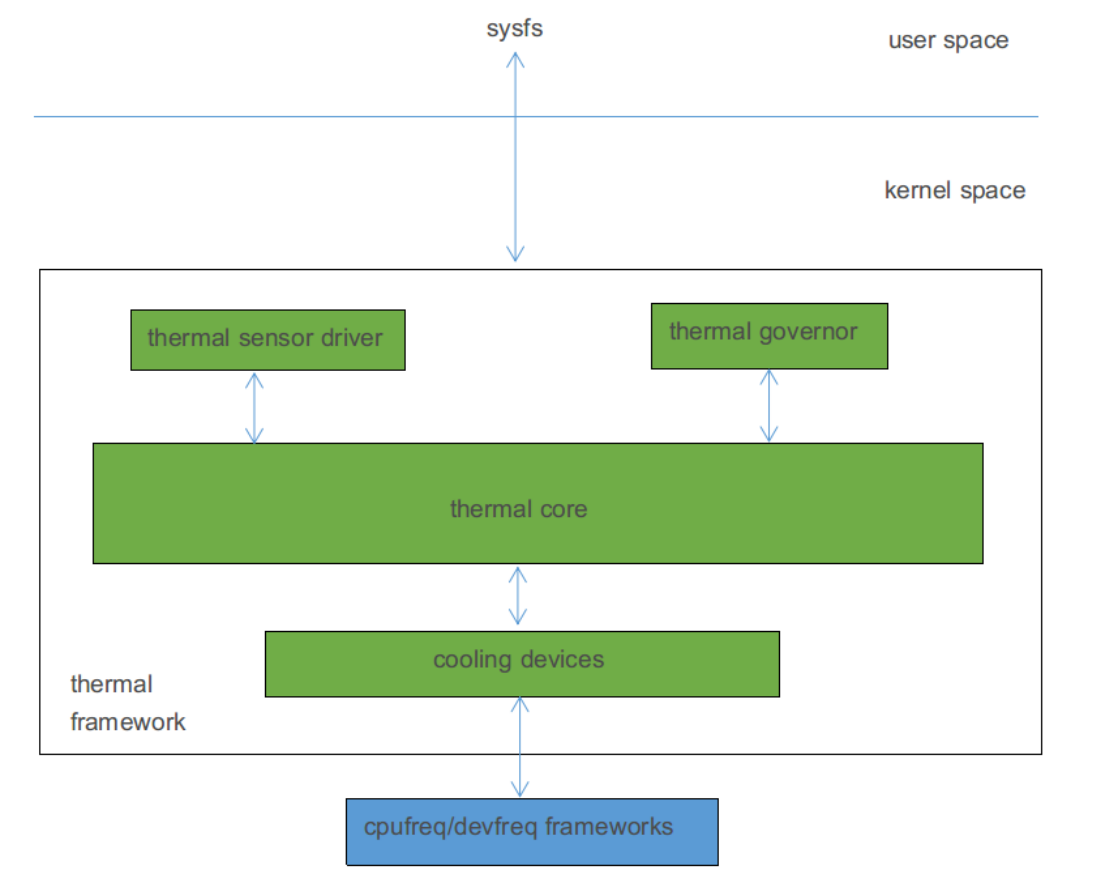
Thermal software architecture (English original)
The Thermal governor decides whether and how far to reduce a cooling device frequency. Linux4.4 governors listed by the source are:
- power_allocator: PID control dynamically assigns power by temperature and converts it to frequency limits.
- step_wise: reduces frequency in steps according to temperature.
- fair share: prioritizes devices with more frequency levels.
- userspace: Chinese says no frequency limit; English adds that it only notifies userspace of thermal events.
Thermal core abstracts governors and drivers and defines their interfaces. A Thermal sensor driver acquires temperature, such as tsadc. A Thermal cooling device is a heat source or cooling device, such as CPU, GPU or DDR.
2. Code Path
Governor related code:
drivers/thermal/power_allocator.    /* power allocator温控策略 */
drivers/thermal/step_wise.c         /* step wise温控策略 */
drivers/thermal/fair_share.c        /* fair share温控策略 */
drivers/thermal/user_space.c        /* userspace温控策略 */
Cooling device related code:
drivers/thermal/devfreq_cooling.c
drivers/thermal/cpu_cooling.c
Core related code:
drivers/thermal/thermal_core.c
Driver related code:
drivers/thermal/rockchip_thermal.c    /* 除了RK3368外的其他平台的tsadc驱动 */
drivers/thermal/rk3368_thermal.c      /* RK3368平台tsadc驱动 */
3. Configuration Method
3.1 Menuconfig Configuration
<*> Generic Thermal sysfs driver  --->
    --- Generic Thermal sysfs driver
    [*]   APIs to parse thermal data out of device tree
    [*]   Enable writable trip points
        Default Thermal governor (power_allocator)  --->    /* default thermal
governor */
    [ ]   Fair-share thermal governor
    [ ]   Step_wise thermal governor                            /* step_wise
governor */
    [ ]   Bang Bang thermal governor
    [*]   User_space thermal governor                           /* user_space
governor */
    -*-   Power allocator thermal governor                      /*
power_allocator governor */
    [*]   generic cpu cooling support                           /* cooling device
*/
    [ ]   Generic clock cooling support
    [*]   Generic device cooling support                        /* cooling device
*/
    [ ]   Thermal emulation mode support
    < >   Temperature sensor driver for Freescale i.MX SoCs
    <*>   Rockchip thermal driver                               /* thermal sensor
driver */
    < >     rk_virtual thermal driver
    <*>     rk3368 thermal driver legacy                        /* thermal sensor
driver */
It is able to select thermal governor through “Default Thermal governor” configuration option. Developers can change it according to the actual product requirement.
3.2 Tsadc Configuration
3.2.1 Example configuration
Tsadc as thermal sensor in the thermal control is used to acquire temperature. Usually need to do the configuration in both DTSI and DTS. Take RK3399 as an example, DTSI includes below configuration:
tsadc: tsadc@ff260000 {
    compatible = "rockchip,rk3399-tsadc";
    reg = <0x0 0xff260000 0x0 0x100>;                   /* 寄存器基地址和寄存器地址总
⻓度 */
    interrupts = <GIC_SPI 97 IRQ_TYPE_LEVEL_HIGH 0>;    /* 中断号及中断触发方式 */
    assigned-clocks = <&cru SCLK_TSADC>;                /* 工作时钟,750KHz */
    assigned-clock-rates = <750000>;
    clocks = <&cru SCLK_TSADC>, <&cru PCLK_TSADC>;      /* 工作时钟和配置时钟 */
    clock-names = "tsadc", "apb_pclk";
    resets = <&cru SRST_TSADC>;                         /* 复位信号 */
    reset-names = "tsadc-apb";
    rockchip,grf = <&grf>;                              /* 引用grf模块,部分平台需要
*/
    rockchip,hw-tshut-temp = <120000>;                  /* 过温重启阈值,120摄氏度 */
    /* tsadc输出引脚配置,支持两种模式:gpio和otpout */
    pinctrl-names = "gpio", "otpout";
    pinctrl-0 = <&otp_gpio>;
    pinctrl-1 = <&otp_out>;
    /*
     * thermal sensor标识,表示tsadc可以作为一个thermal sensor,
     * 并指定了引用tsadc节点的时候需要带几个参数。
     * 如果SoC里面只有一个tsadc,可以设置为0,超过一个必须设置为1。
     */
    #thermal-sensor-cells = <1>;
    status = "disabled";
};

/* IO口配置 */
pinctrl: pinctrl {
    ...
    tsadc {
        /* 配置为gpio模式 */
        otp_gpio: otp-gpio {
            rockchip,pins = <1 6 RK_FUNC_GPIO &pcfg_pull_none>;
        };
        /* 配置为over temperature protection模式 */
        otp_out: otp-out {
            rockchip,pins = <1 6 RK_FUNC_1 &pcfg_pull_none>;
        };
    };
    ....
}
DTS configuration is mainly used to select CRU reset or GPIO reset, low voltage reset or high voltage reset. Need to pay attention to that, if want to configure as GPIO reset, hardware needs to connect tsadc output pin to PMIC reset pin, otherwise it only can be configured as CRU reset.
&tsadc {
    rockchip,hw-tshut-mode = <1>;        /* tshut mode 0:CRU 1:GPIO */
    rockchip,hw-tshut-polarity = <1>;    /* tshut polarity 0:LOW 1:HIGH */
    status = "okay";
};
Refer to Documentation/devicetree/bindings/thermal/rockchip-thermal.txt.
3.2.2 RK3576
tsadc: tsadc@2ae70000 {
    compatible = "rockchip,rk3576-tsadc";
    reg = <0x0 0x2ae70000 0x0 0x400>;                   /* 寄存器基地址和寄存器地址总
⻓度 */
    interrupts = <GIC_SPI 123 IRQ_TYPE_LEVEL_HIGH>;     /* 中断号及中断触发方式 */
    clocks = <&cru CLK_TSADC>, <&cru PCLK_TSADC>;       /* 工作时钟和配置时钟 */
    clock-names = "tsadc", "apb_pclk";
    assigned-clocks = <&cru CLK_TSADC>;                 /* 工作时钟,2MHz */
    assigned-clock-rates = <2000000>;
    resets = <&cru SRST_TSADC>, <&cru SRST_P_TSADC>;    /* 复位信号 */
    reset-names = "tsadc", "tsadc-apb";
    #thermal-sensor-cells = <1>;
    rockchip,hw-tshut-temp = <120000>;                  /* 过温重启阈值,120摄氏度 */
    rockchip,hw-tshut-mode = <0>;                       /* tshut mode 0:CRU
1:GPIO */
    rockchip,hw-tshut-polarity = <0>;                   /* tshut polarity 0:LOW
1:HIGH */
    status = "disabled";
};
When rockchip,hw-tshut-mode is CRU, pinctrl-names, pinctrl-0 and pinctrl-1 are unnecessary; the source recommends CRU. GPIO mode requires all three properties:
tsadc: tsadc@2ae70000 {
    ...
    rockchip,hw-tshut-polarity = <1>;    /* tshut polarity 0:LOW 1:HIGH */
    pinctrl-names = "gpio", "otpout";
    pinctrl-0 = <&otp_gpio>;
    pinctrl-1 = <&tsadc_ctrl_pins>;
    status = "disabled";
};
/* rk3576-pinctrl.dtsi中需要有otp_gpio和tsadc_ctrl_pins */
&pinctrl {
    ...
    tsadc_ctrl {
        /omit-if-no-ref/
        otp_gpio: otp-gpio {
            rockchip,pins = <0 RK_PA1 RK_FUNC_GPIO &pcfg_pull_none>;
        };
        /omit-if-no-ref/
        tsadc_ctrl_pins: tsadc_ctrl-pins {
            rockchip,pins =
                /* tsadc_ctrl_org */
                <0 RK_PA1 10 &pcfg_pull_none>;
        };
    };
    ....
}
3.3 Power Allocator Governor Configuration
Power allocator thermal governor introduces PID (Proportion-Integral-Differential) control to dynamically allocate power for cooling devices according to current temperature. When the temperature is low, the allocatable power is relatively large, that is, the operating frequency is high. As the temperature rises, the allocatable power gradually decreases and the operating frequency also gradually decreases, so as to limit the frequency according to the temperature.
3.3.1 Example configuration
3.3.1.1 CPU configuration
CPU as cooling device in thermal control needs to include “#cooling-cells”, “dynamic-power- coefficient” attributes in the node. Take RK3399 as an example:
cpu_l0: cpu@0 {
    device_type = "cpu";
    compatible = "arm,cortex-a53", "arm,armv8";
    reg = <0x0 0x0>;
    enable-method = "psci";
    #cooling-cells = <2>;                 /* cooling device标识,表示该设备可以作为一
个cooling device */
    clocks = <&cru ARMCLKL>;
    cpu-idle-states = <&CPU_SLEEP &CLUSTER_SLEEP>;
    dynamic-power-coefficient = <100>;    /* 动态功耗常数C,动态功耗公式为Pdyn=C*V^2*F
*/
};
...
cpu_b0: cpu@100 {
    device_type = "cpu";
    compatible = "arm,cortex-a72", "arm,armv8";
    reg = <0x0 0x100>;
    enable-method = "psci";
    #cooling-cells = <2>;                 /* cooling device标识,表示该设备可以作为一
个cooling device */
    clocks = <&cru ARMCLKB>;
    cpu-idle-states = <&CPU_SLEEP &CLUSTER_SLEEP>;
    dynamic-power-coefficient = <436>;    /* 用于计算动态功耗的参数 */
};
3.3.1.2 GPU configuration
GPU as cooling device in thermal control needs to include “#cooling-cells” attribute in the node and power_model subnode. Take RK3399 as an example:
gpu: gpu@ff9a0000 {
    compatible = "arm,malit860",
    "arm,malit86x",
    "arm,malit8xx",
    "arm,mali-midgard";

    reg = <0x0 0xff9a0000 0x0 0x10000>;

    interrupts = <GIC_SPI 19 IRQ_TYPE_LEVEL_HIGH 0>,
    <GIC_SPI 20 IRQ_TYPE_LEVEL_HIGH 0>,
    <GIC_SPI 21 IRQ_TYPE_LEVEL_HIGH 0>;
    interrupt-names = "GPU", "JOB", "MMU";

    clocks = <&cru ACLK_GPU>;
    clock-names = "clk_mali";
    #cooling-cells = <2>;                     /* cooling device标识,表示该设备可以作
为一个cooling device */
    power-domains = <&power RK3399_PD_GPU>;
    power-off-delay-ms = <200>;
    status = "disabled";

    gpu_power_model: power_model {
        compatible = "arm,mali-simple-power-model";
        static-coefficient = <411000>;    /* 用于计算静态功耗的参数 */
        dynamic-coefficient = <733>;      /* 用于计算动态功耗的参数 */
        ts = <32000 4700 (-80) 2>;        /* 用于计算静态功耗的参数 */
        thermal-zone = "gpu-thermal";     /* 从gpu-thermal获取温度,用于计算静态功耗
*/
    };
};
3.3.1.3 Thermal Zone configuration
Thermal zone node is mainly used to configure the related parameters of thermal governor and generate the corresponding user mode interface. Take RK3399 as an example:
thermal_zones: thermal-zones {
    /* 一个节点对应一个thermal zone,并包含温控策略相关参数 */
    soc_thermal: soc-thermal {
        /* 温度高于trip-point-0指定的值,每隔20ms获取一次温度 */
        polling-delay-passive = <20>; /* milliseconds */
        /* 温度低于trip-point-0指定的值,每隔1000ms获取一次温度 */
        polling-delay = <1000>; /* milliseconds */
        /* 温度等于trip-point-1指定的值时,系统分配给cooling device的能量 */
        sustainable-power = <1000>; /* milliwatts */
        /* 当前thermal zone通过tsadc0获取温度 */
        thermal-sensors = <&tsadc 0>;

        /* trips包含不同温度阈值,不同的温控策略,配置不一定相同 */
        trips {
            /*
             * 温控阈值,超过该值温控策略开始工作,但不一定⻢上限制频率,
             * power小到一定程度才开始限制频率
             */
            threshold: trip-point-0 {
                /* 超过70摄氏度,温控策略开始工作,并且70摄氏度也是tsadc触发中断的一个阈值
*/
                temperature = <70000>; /* millicelsius */
                /* 温度低于temperature-hysteresis时触发中断,当前未实现,但是框架要求必须
填 */
                hysteresis = <2000>; /* millicelsius */
                type = "passive"; /* 表示超过该温度值时,使用polling-delay-passive */
            };
            /* 温控目标温度,期望通过降频使得芯片不超过该值 */
            target: trip-point-1 {
                /* 期望通过降频使得芯片不超过85摄氏度,并且85摄氏度也是tsadc触发中断的一个阈
值 */
                temperature = <85000>; /* millicelsius */
                /* 温度低于temperature-hysteresis时触发中断,当前未实现,但是框架要求必须
填 */
                hysteresis = <2000>; /* millicelsius */
                type = "passive"; /* 表示超过该温度值时,使用polling-delay-passive */
            };
            /* 过温保护阈值,如果降频后温度仍然上升,那么超过该值后,让系统重启 */
            soc_crit: soc-crit {
                /* 超过115摄氏度重启,并且115摄氏度也是tsadc触发中断的一个阈值  */
                temperature = <115000>; /* millicelsius */
                /* 温度低于temperature-hysteresis时触发中断,当前未实现,但是框架要求必须
填 */
                hysteresis = <2000>; /* millicelsius */
                type = "critical"; /* 表示超过该温度值时,重启 */
            };
        };

        /* cooling device配置节点,每个子节点代表一个cooling device */
        cooling-maps {
            map0 {
                /*
                 * 表示在target trip下,该cooling device才起作用,
                 * 对于power allocater策略必须填target
                 */
                trip = <&target>;
                /* A53做为cooloing device, THERMAL_NO_LIMIT不起作用,但必须填 */
                cooling-device =
                    <&cpu_l0 THERMAL_NO_LIMIT THERMAL_NO_LIMIT>;
                contribution = <4096>; /* 计算功耗时乘以4096/1024倍,用于调整降频顺序和
尺度 */
            };
            map1 {
                /*
                 * 表示在target trip下,该cooling device才起作用,
                 * 对于power allocater策略必须填target
                 */
                trip = <&target>;
                /* A72做为cooloing device, THERMAL_NO_LIMIT不起作用,但必须填 */
                cooling-device =
                    <&cpu_b0 THERMAL_NO_LIMIT THERMAL_NO_LIMIT>;
                contribution = <1024>;/* 计算功耗时乘以1024/1024倍,用于调整降频顺序和尺
度 */
            };
            map2 {
                /*
                 * 表示在target trip下,该cooling device才起作用,
                 * 对于power allocater策略必须填target
                 */
                trip = <&target>;
                /* GPU做为cooloing device, THERMAL_NO_LIMIT不起作用,但必须填 */
                cooling-device =
                    <&gpu THERMAL_NO_LIMIT THERMAL_NO_LIMIT>;
                contribution = <4096>;/* 计算功耗时乘以4096/1024倍,用于调整降频顺序和尺
度 */
            };
        };
    };
    /* 一个节点对应一个thermal zone,并包含温控策略相关参数,当前thermal zone只用于获取温度
*/
    gpu_thermal: gpu-thermal {
        /* 包含温控策略配置的情况下才起作用,架要求必须填 */
        polling-delay-passive = <100>; /* milliseconds */
        /* 每隔1000ms获取一次温度 */
        polling-delay = <1000>; /* milliseconds */

        /* 当前thermal zone通过tsadc1获取温度 */
        thermal-sensors = <&tsadc 1>;
    };
};
Refer to Documentation/devicetree/bindings/thermal/thermal.txt and Documentation/thermal/power_allocator.txt.
3.3.1.4 Thermal parameter adjustment
Some parameters are related with the chipset and usually no need to change. Some parameters need to be adjusted according to the actual product requirement. Generally you can do as below steps:
- Confirm the target temperature. Assume that we want the thermal control starts to work when the temperature is over 70 degree (acquire the temperature more frequently), the highest temperature not to exceed 85 degree, and reboot the system when over 115 degree. Then we can do below configuration:
thermal_zones: thermal-zones {
    soc_thermal: soc-thermal {
        ....
        trips {
            threshold: trip-point-0 {
                /*
                 * 70度以上温控开始工作,缩短了获取温度的是时间间隔,但不一定⻢上降频,
                 * 还跟sustainable-power有关
                 */
                temperature = <70000>; /* millicelsius */
                hysteresis = <2000>; /* millicelsius */
                type = "passive";
            };
            target: trip-point-1 {
                /* 期望最高温度不超过85度 */
                temperature = <85000>; /* millicelsius */
                hysteresis = <2000>; /* millicelsius */
                type = "passive";
            };
            soc_crit: soc-crit {
                /* 超过115度系统重启 */
                temperature = <115000>; /* millicelsius */
                hysteresis = <2000>; /* millicelsius */
                type = "critical";
            };
        };
    ...
    }
};
- Confirm the cooling device. Take RK3399 as an example, some products need to use CPU and GPU, we can do below configuration:
thermal_zones: thermal-zones {
    soc_thermal: soc-thermal {
        ...
        /* A53、A72、GPU三个模块都作为cooling device,可通过降频降温 */
        cooling-maps {
            map0 {
                trip = <&target>;
                cooling-device =
                    <&cpu_l0 THERMAL_NO_LIMIT THERMAL_NO_LIMIT>;
                contribution = <4096>;
            };
            map1 {
                trip = <&target>;
                cooling-device =
                    <&cpu_b0 THERMAL_NO_LIMIT THERMAL_NO_LIMIT>;
                contribution = <1024>;
            };
            map2 {
                trip = <&target>;
                cooling-device =
                    <&gpu THERMAL_NO_LIMIT THERMAL_NO_LIMIT>;
                contribution = <4096>;
            };
        };
    ...
    };
};
Some products only use CPU, we can do below configuration:
thermal_zones: thermal-zones {
    soc_thermal: soc-thermal {
        ...
        /* 只有A53、A72两个模块作为cooling device,可通过降频降温 */
        cooling-maps {
            map0 {
                trip = <&target>;
                cooling-device =
                    <&cpu_l0 THERMAL_NO_LIMIT THERMAL_NO_LIMIT>;
                contribution = <4096>;
            };
            map1 {
                trip = <&target>;
                cooling-device =
                    <&cpu_b0 THERMAL_NO_LIMIT THERMAL_NO_LIMIT>;
                contribution = <1024>;
            };
        };
    ...
    };
};
- Adjust sustainable-power. The range from 70 degree to 85 degree set in step (1) means the system will provide a relatively large power value with 70 degree, when the temperature rises, power gradually decreases, when power decreases to a certain extent, it will start to decrease the frequency, if the temperature keeps rising, power keeps decreasing, and the frequency also keeps decreasing. So it only shorten the time interval to acquire the temperature when over 70 degree, not definitely decrease the frequency, you can change the sustainable value to adjust the time to decrease the frequency. Assume that when over 70 degree the thermal control strategy starts to work, that is to shorten the time interval to acquire the temperature, starts to limit the frequency when 75 degree (this setting can reduce the frequency fluctuation at the beginning of the thermal control), not to exceed 85 degree at most. Then we can set the power value with 75 degree equal to the sum of the max power consumption of all cooling devices, and then gradually decrease to debug, until it meets our requirement. The power consumption contains static power consumption and dynamic power consumption. The compution formulas are as below:
Static power: a, b, c, d and C are DTSI constants, normally left at defaults; T is temperature and V voltage, adjusted for the actual conditions. Dynamic power: C is a DTSI constant left at its default, V is voltage and F frequency, chosen for the actual conditions. Original formulas and comments follow.
静态功耗公式:
    /* a、b、c、d、C是常量,在DTSI中配置,保持默认值即可,T是温度,V是电压,需要根据实际情况调
整 */
    t_scale = (a * T^3) + (b * T^2) + (c * T) + d
    v_scale = V^3
    P(s)= C * T_scale * V_scale
动态功耗公式:
    /* C是常量,在DTSI中配置,保持默认值即可,V是电压,F是频率,需要根据实际情况调整 */
    P(d)= C * V^2 * F
Take RK3399 as an example, assume that A53, A72 and GPU are all working and need to be limited, the actually used max frequencies are 1416MHz(1125mV), 1800MHz(1200mV) and 800MHz(1100mV), then we can compute the power consumption as below:
A53 dynamic power uses dynamic-power-coefficient C=100, V=1125mV, F=1416MHz and four cores. A72 uses C=436, V=1200mV, F=1800MHz and two cores. GPU dynamic power uses dynamic-coefficient C=733, V=1100mV and F=800MHz. GPU static power uses static-coefficient=411000 and ts=<32000 4700 -80 2>: C=411000, a=2, b=-80, c=4700, d=32000, T=75000mC at throttling start, V=1100mV. The source includes static power only for GPU. These are calculation examples; it suggests using an Excel table for convenience.
A53 动态功耗:C = 100(dynamic-power-coefficient配置为100),V = 1125mV,F = 1416MHz,
四核
    P_d_a53 = 100 * 1125 * 1125 * 1416 * 4 / 1000000000 = 716 mW

A72 动态功耗:C = 436(dynamic-power-coefficient配置为436),V = 1200mV,F = 1800MHz,
双核
    P_d_a72 = 436 * 1200 * 1200 * 1800 * 2 / 1000000000 = 2260 mW

GPU 动态功耗:C = 733(dynamic-coefficient配置为733),V = 1100mV,F = 800MHz
    P_d_gpu = 733 * 1100 * 1100 * 800 / 1000000000 = 709 mW

GPU 静态功耗:DTSI中static-coefficient配置为411000,ts配置为32000 4700 -80 2,则C =
411000,
a = 2,b = -80,c = 4700,d = 32000,温度为开始降频的温度值T = 75000mC,V = 1100mV
    t_scale = ( 2 * 75000 * 75000 * 75000 / 1000000 ) + ( -80 * 75000 * 75000 /
1000) +
    ( 4700 * 75000 ) + 32000 * 1000 =  778250
    v_scale = 1100 * 1100 * 1100 / 1000000 = 1331
    P_s_gpu = 411000 * 778250 / 1000000 * 1331 / 1000000 = 425mW

    P_max = P_d_a53 + P_d_a72 + P_d_gpu + P_s_gpu = 4110mW

    注意:当前只有GPU有计算静态功耗;当前只是列出计算方法,实际上通过exel表格计算比较方便;
We expect to decrease the frequency over 75 degree, so we can set the power with 75 degree as the biggest power, and then compute through below formula to get the sustainable value:
sustainable + 2 * sustainable / (target- threshold) * (target- 75) = P_75
sustainable + 2 * sustainable / (85 - 70) * (85 - 75) = 4110
sustainable = 1761mW
Firstly set sustainable-power as 1761 in DTSI, actually test the different scenarios such as Antutu, Geekbench and so on, capture the trace data, analyze the change of the frequency and temperature, or use lisa tool to draw picture to analyze, to see if match with the expectation or not, if not match with the expectation, decrease the value, continue debugging, until it meets the expectation.
- Adjust contribution. Adjust the corresponding contribution of cooling device can adjust the sequence and extent while decreasing the frequency, even if not configured, it also will be set as 1024. If in high temperature environment, both A53 and A72 are running with full load, it is found that the frequency of A53 is easier to be decreased, if now want to decrease the frequency of A72 with priority, you can increase the contribution of A53, for example:
thermal_zones: thermal-zones {
    soc_thermal: soc-thermal {
        ...
        cooling-maps {
            map0 {
                trip = <&target>;
                cooling-device =
                    <&cpu_l0 THERMAL_NO_LIMIT THERMAL_NO_LIMIT>;
                contribution = <4096>; /* 从默认值1024,改为4096 */
            };
            map1 {
                trip = <&target>;
                cooling-device =
                    <&cpu_b0 THERMAL_NO_LIMIT THERMAL_NO_LIMIT>;
                contribution = <1024>;
            };
        };
    ...
    };
};
- Acquire trace data to analyze. Firstly, need to enable the trace related configurations in menuconfig.
Kernel hacking  --->
    [*] Tracers  --->
        --- Tracers
        [ ]   Kernel Function Tracer
        [ ]   Enable trace events for preempt and irq disable/enable
        [ ]   Interrupts-off Latency Tracer
        [ ]   Preemption-off Latency Tracer
        [ ]   Scheduling Latency Tracer
        [*]   Trace process context switches and events
        [ ]   Trace syscalls
        [ ]   Create a snapshot trace buffer
        Branch Profiling (No branch profiling)  --->
        [ ]   Trace max stack
        [ ]   Support for tracing block IO actions
        [ ]   Add tracepoint that benchmarks tracepoints
        < >   Ring buffer benchmark stress tester
        [ ]   Ring buffer startup self test
        [ ]   Show enum mappings for trace events
        [*]   Trace gpio events
Method 1: capture log through trace-cmd, there is trace-cmd in lisa tool package, refer to lisa related documents for lisa environment installation. Push trace-cmd to the target board through adb, and then acquire thermal control related log through below commands:
/* -b指定缓存的大小,单位是Kb,不同的平台DDR容量不一样,可能需要调整 */
trace-cmd record -e thermal -e thermal_power_allocator -b 102400
Ctrl+C can stop recording log, generate the trace.dat file in current directory, transform the format through below command:
trace-cmd report trace.dat > trace.txt
Then use adb to pull the file to PC, directly open to analyze or use lisa tool to analyze. Or you can pull the trace.dat file to PC, and use trace-cmd to convert it into trace.txt in PC. Method 2: if there is no trace-cmd tool, use command can also acquire thermal control related log. Enable thermal control related trace:
echo 1 > /sys/kernel/debug/tracing/events/thermal/enable
echo 1 > /sys/kernel/debug/tracing/events/thermal_power_allocator/enable
echo 1 > /sys/kernel/debug/tracing/tracing_on
Directly print out the trace data, and save as a file:
cat /sys/kernel/debug/tracing/trace
Or directly pull out the file through adb:
/* 获取数据后,可以直接打开trace.txt进行分析,或者使用lisa工具分析 */
adb pull /sys/kernel/debug/tracing/trace ./trace.txt
Other operations:
echo 0 > /sys/kernel/debug/tracing/tracing_on  /* 暂停抓取数据 */
echo 0 > /sys/kernel/debug/tracing/trace       /* 清空之前的数据 */
3.3.2 RK3576
Configure the CPU as in the example; its dynamic power coefficient is normally unchanged. The GPU does not calculate static power and needs no power_model subnode; configure it like a CPU:
gpu: gpu@27800000 {
    ...
    #cooling-cells = <2>;                  /* cooling device标识,表示该设备可以作为一
个cooling device */
    dynamic-power-coefficient = <1625>;    /* 用于计算动态功耗的参数 */
    status = "disabled";
};
Use the example for Thermal Zone configuration and parameter tuning. For sustainable-power, the maximum frequencies/voltages of little cores, big cores and GPU are 2208MHz/950mV, 2304MHz/950mV and 950MHz/850mV:
Dynamic power: C is the DTSI constant, normally unchanged; V is voltage and F frequency, selected for the actual situation.
动态功耗公式:
    /* C是常量,在DTSI中配置,保持默认值即可,V是电压,F是频率,需要根据实际情况调整 */
    P(d)= C * V^2 * F
The source labels the first cluster A53: dynamic-power-coefficient C=120, V=950mV, F=2208MHz, four cores. It labels the second A72: C=320, V=950mV, F=2304MHz, four cores. GPU: C=1625, V=850mV, F=950MHz. The source presents only the calculation method and suggests an Excel table; the core labels remain uncorrected pending verification.
A53 动态功耗:C = 120(dynamic-power-coefficient配置为120),V = 950mV,F = 2208MHz,四
核
    P_d_a53 = 120 * 950 * 950 * 2208 * 4 / 1000000000 = 957 mW

A72 动态功耗:C = 320,V = 950mV,F = 2304MHz,四核
    P_d_a72 = 320 * 950 * 950 * 2304 * 4 / 1000000000 = 2662 mW

GPU 动态功耗:C = 1625,V = 850mV,F = 950MHz
    P_d_gpu = 1625 * 850 * 850 * 950 / 1000000000 = 1115 mW

    P_max = P_d_a53 + P_d_a72 + P_d_gpu = 4734mW

    注意:当前只是列出计算方法,实际上通过exel表格计算比较方便;
If control should start above 75°C with more frequent sampling, throttling should begin after 77°C and temperature should not exceed 85°C, set threshold=75 and target=85. Set the power at 77°C equal to maximum power, then calculate sustainable using the following original equations:
sustainable + 2 * sustainable / (target- threshold) * (target- 77) = P_max
sustainable + 2 * sustainable / (85 - 70) * (85 - 77) = 4734
sustainable = 1353mW
Initially set sustainable-power=1353 in DTSI. Test Antutu, Geekbench and other scenarios, capture traces and analyze frequency/temperature directly or with lisa plots. If results differ from expectations, adjust the value and repeat.
4. User Interface Introduction
User interface is in the directory of /sys/class/thermal/, and the detailed contents correspond to the thermal zone node configuration in DTSI. Some platforms only have one sub node under the thermal zone node, so there is only thermal_zone0 sub directory under the directory of /sys/class/thermal/. Some platforms have two sub nodes, and correspondingly there will be thermal_zone0 and thermal_zone1 sub directories under the directory of /sys/class/thermal/. Through user mode interface it is able to switch thermal control strategy, check current temperature and so on. Take RK3399 as an example, the /sys/class/thermal/thermal_zone0/ directory includes below commonly used information:
Field descriptions: temp is the current temperature; available_policies lists supported governors and policy selects the current one. sustainable_power is the power corresponding to the desired maximum temperature. integral_cutoff controls the PID integral term: current temperature minus desired maximum temperature must be less than integral_cutoff. k_d and k_i are the D and I parameters; k_po and k_pu are P parameters. With mode=enabled, periodic temperature readings determine whether throttling is needed; disabled turns this function off. type identifies the thermal zone. The trip_point_0_*, trip_point_1_* and trip_point_2_* fields correspond to the thresholds configured in trips. Cooling-device states correspond to cooling-maps: cdev0 represents one cooling device, and some platforms also expose cdev1, cdev2, etc. Its cur_state is the current frequency level, max_state is the maximum number of levels as described by the source, and type is the device type. cdev0_weight is the factor applied when calculating that cooling device’s power. The original field list and comments are retained below.
temp                                /* 当前温度 */
available_policies                  /* 支持的温控策略 */
policy                              /* 当前使用的温控策略 */
sustainable_power                   /* 期望的最高温度下对应的power值 */
integral_cutoff                     /* PID算法中I的触发条件:当前温度-期望的最高温度
<integral_cutoff */
k_d                                 /* PID算法中计算D的时候用的参数 */
k_i                                 /* PID算法中计算I的时候用的参数 */
k_po                                /* PID算法中计算P的时候用的参数 */
k_pu                                /* PID算法中计算P的时候用的参数 */
mode                                /* enabled:自带定时获取温度,判断是否需要降频。
disabled关闭该功能 */
type                                /* 当前thermal zone的类型 */
/* 不同的温度阈值,对应trips节点的配置 */
trip_point_0_hyst
trip_point_0_temp
trip_point_0_type
trip_point_1_hyst
trip_point_1_temp
trip_point_1_type
trip_point_2_hyst
trip_point_2_temp
trip_point_2_type
/* 不同cooling devic的状态,对应cooling-maps节点的配置 */
cdev0                               /* 代表一个cooling devic,有的平台还有cdev1、
cdev2等 */
    cur_state                   /* 该cooling device当前频率的档位 */
    max_state                   /* 该cooling device最多有几个档位 */
    type                        /* 该cooling device的类型 */
cdev0_weight                        /* 该cooling devic在计算power时扩大的倍数 */
Refer to Documentation/thermal/sysfs-api.txt.
5. Common Issues
5.1 Disable Thermal Control
Method 1: set the default thermal governor as user_space in menuconfig.
<*> Generic Thermal sysfs driver  --->
    --- Generic Thermal sysfs driver
    [*]   APIs to parse thermal data out of device tree
    [*]   Enable writable trip points
        Default Thermal governor (user_space)  --->  /* power_allocator改为
user_space */
Method 2: Use command to disable the thermal control after boot up. Firstly, switch the thermal governor to user_space, that is, change the policy node in the user interface to user_space; Or set the mode as disabled; then, remove the frequency limitation, that is, set cur_state of all cdev in the user interface as 0. Take RK3399 as an example, switch governor to user_space:
echo user_space > /sys/class/thermal/thermal_zone0/policy
Or set the mode as disabled:
echo disabled > /sys/class/thermal/thermal_zone0/mode
Remove the frequency limitation:
/* 具体有多少个cdev,根据实际情况修改 */
echo 0 > /sys/class/thermal/thermal_zone0/cdev0/cur_state
echo 0 > /sys/class/thermal/thermal_zone0/cdev1/cur_state
echo 0 > /sys/class/thermal/thermal_zone0/cdev2/cur_state
5.2 Acquire Current Temperature
Just look at the temp node in the directory of thermal_zone0 or thermal_zone1. Take RK3399 as an example, input below command in debug console to acquire CPU temperature:
cat /sys/class/thermal/thermal_zone0/temp
Input below command in debug console to acquire GPU temperature:
cat /sys/class/thermal/thermal_zone1/temp