
Plattformreferenz: vollständige USB-Herstellerunterlagen für RK3576 (CN V1.1.0 / EN V1.2.0), Kernelbasis Linux-6.1. Behandelt werden Controller-/PHY-Schaltungen, Versorgung, Anschlüsse und DTS für produktspezifische Entwicklung. Passende ArmSoM-Boards und SDK/BSPs sind nicht bestätigt; keine Hardwarevalidierung. Schaltplan, SoC/Kernel, Patches, PHY-Versorgung, GPIO, PD-Controller und Verkabelung prüfen. Verbrauchstabellen und Befehle sind Herstellerbeispiele, keine ArmSoM-Messungen. ZH verwendet chinesische, EN/RU/DE englische Originalbilder. Quellunterschiede und eigene Codebeispiele bleiben getrennt nachvollziehbar.
1. USB-Controller und PHY des RK3576
RK3576 unterstützt zwei unabhängige USB-3.1-OTG-Controller, zwei unabhängige USB-2.0-PHYs, einen USB-3.1/DP-Combo-PHY und einen USB-3.1/SATA/PCIe-Combo-PHY. Weitere Controllermerkmale stehen im RK3576 TRM. Neue Funktionen:
- OTG0 und OTG1 unterstützen MMU und können hardwareseitig Speicher jenseits von 4G adressieren.
- OTG1 unterstützt CCI für Cache-Kohärenz; die CPU muss den Cache nicht leeren. OTG0 unterstützt dies nicht.
- OTG0 DP/DM sind mit UART/JTAG multiplexiert. Das SDK aktiviert dies standardmäßig; benötigt wird die RK-USB-to-DEBUG-Adapterplatine. Hinweise:
- Physikalische Datenrate: USB 3.1 Gen1 5Gbps, USB 2.0 480Mbps.
- USB 3.1/DP Combo PHY hat vier Lanes und unterstützt gleichzeitig USB 3.1 und zwei DP-Lanes.
- USB 3.1/SATA/PCIe Combo PHY arbeitet jeweils nur in einem Modus: USB 3.1 und SATA/PCIe schließen sich aus. Tabelle 1: Verbindung der USB-Controller und PHYs des RK3576.
| USB-Schnittstelle (Schaltplan) | USB-Controller | USB PHY |
|---|---|---|
| USB OTG0 | OTG0 (DWC3&xHCI) |
USB3.1/DP ComboPHY + USB2.0 PHY0 |
| USB OTG1 | OTG1 (DWC3&xHCI) |
USB3.1/SATA/PCIe ComboPHY1 + USB2.0 PHY1 |
Tabelle 2 ordnet die USB-Controller des RK3576 den USB-Datenpins am Chip zu.
| USB-Controller/Pin | USB-Datenpins RK3576 |
|---|---|
| USB 3.1 OTG0 | USB2_OTG0_DP/USB2_OTG0_DM, USB3_OTG0_SSRX1P/USB3_OTG0_SSRX1N, USB3_OTG0_SSTX1P/USB3_OTG0_SSTX1N, USB3_OTG0_SSRX2P/USB3_OTG0_SSRX2N, USB3_OTG0_SSTX2P/USB3_OTG0_SSTX2N, |
| USB 3.1 OTG1 | USB2_OTG1_DP/USB2_OTG1_DM, USB3_OTG1_SSTXP/USB3_OTG1_SSTXN, USB3_OTG1_SSRXP/USB3_OTG1_SSRXN, |
Abbildung 1 zeigt interne Verbindungen von USB-Controllern und PHYs sowie die üblichen zugehörigen physischen USB-Schnittstellen.
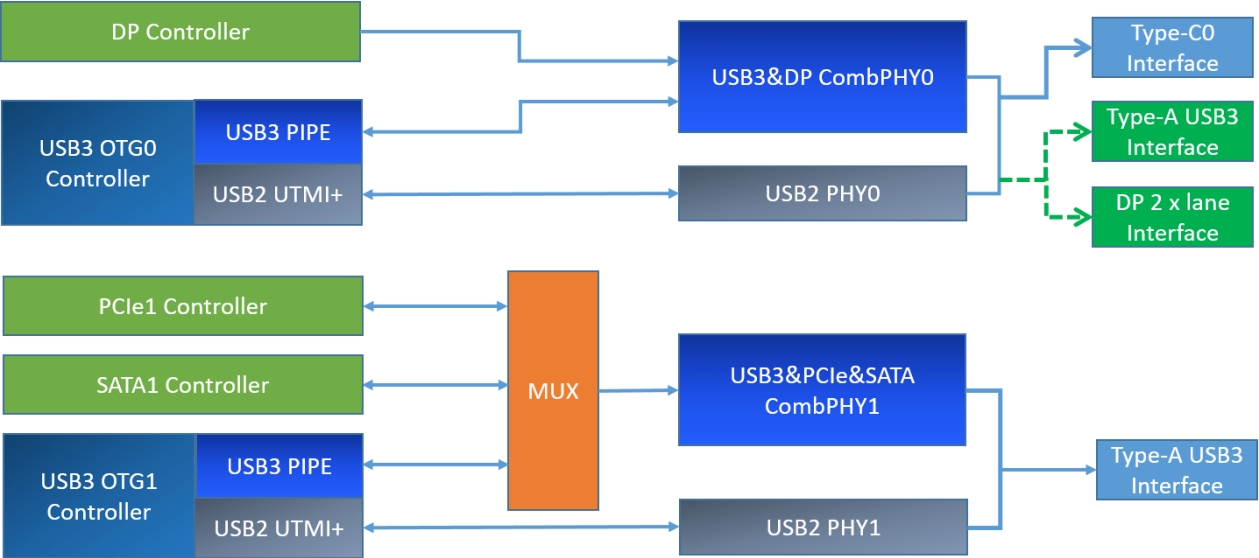
Abbildung 1: Verbindung der USB-Controller und PHYs des RK3576. Hinweise:
- Die Unterstützung ist nicht auf Type-C/A in Abbildung 1 beschränkt: übliche Type-C USB 2.0/3.1, Type-A USB 2.0/3.1 und Micro USB 2.0/3.1 sind ebenfalls möglich. Der USB-Treiber in Linux-6.1 ist bereits für unterschiedliche Schaltungen und Anschlussarten vorbereitet. Entwickler müssen Linux USB DTS entsprechend der Produktschaltung konfigurieren, um die gewünschte Funktion zu aktivieren. Details im Abschnitt RK3576 USB DTS.
- Besondere Einschränkung: OTG1/PCIe1/SATA1 schließen sich beim Buszugriff aus. Nutzt die Hardware PCIe1 oder SATA1, sind sowohl USB2 als auch USB3 von OTG1 unbenutzbar.
2. RK3576 USB Config Map
Die zwei unabhängigen Controller ermöglichen die Produktvarianten in Abbildungen 2–4. OTG0 bietet fünf Schaltungen:
- Config0: Type-C0 USB3.1 OTG0 mit DP.
- Config1: USB 2.0 OTG0 + DP 4 x Lane (Swap off).
- Config2: USB 2.0 OTG0 + DP 4 x Lane (Swap on).
- Config3: USB 3.1 OTG0 + DP 2 x Lane (Swap on).
- Config4: USB 3.1 OTG0 + DP 2 x Lane (Swap off).
OTG1 bietet Config0 USB 2.0 only OTG1 und Config1 USB 3.1 OTG1. Die detaillierte Karte steht im Abschnitt USB/DP Configure Map des RK3576-SDK-EVB-Referenzschaltplans. Hinweise:
- USB 2.0/3.1 OTG1 darf nicht gleichzeitig mit PCIe1/SATA1 verwendet werden.
- USBDP-Lane-Zuordnung: Swap off — Lane0/1/2/3 TxData → Lane0/1/2/3_TXDP/N; Swap on — Lane0/1/2/3 TxData → Lane2/3/0/1_TXDP/N.
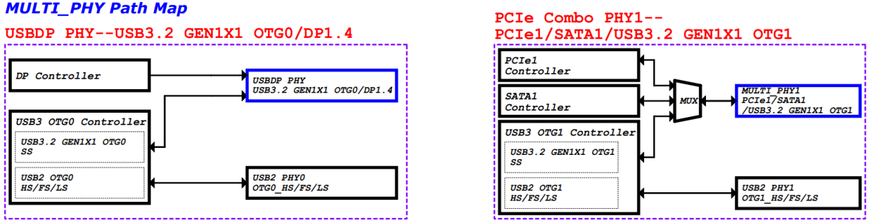
Abbildung 2: RK3576 USB Path Map.
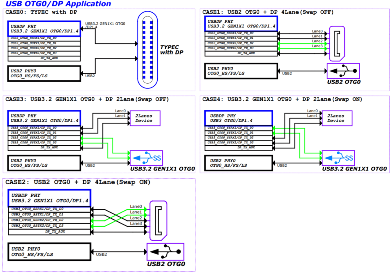
Abbildung 3: RK3576 OTG0 USBDP Path Map.
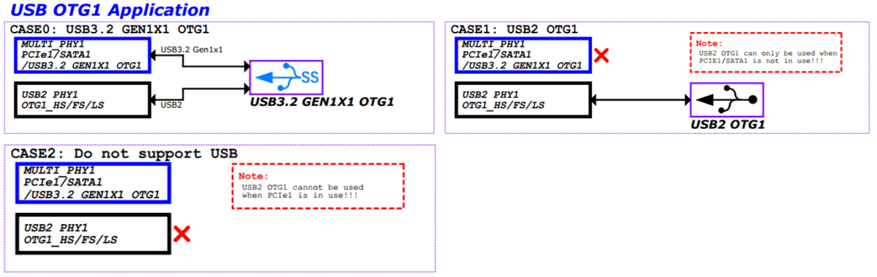
Abbildung 4: RK3576 OTG1 MULTI PHY Path Map.
3. USB-Hardwareschaltung des RK3576
Dieser Abschnitt beschreibt die unterstützten praktischen Schaltungsvarianten. Verfügbare Schnittstellen: USB30/DP1.4 MULTI0 und USB30/PCIE2.0/SATA30 MULTI1.
3.1 Versorgung und Verbrauchssteuerung des USB-Controllers
Die Controller werden durch VD_LOGIC versorgt. Eigene Power-Domains: USB3.1 OTG0 liegt in PD_USB, USB3.1 OTG1 in PD_PHP. Der Linux-Treiber schaltet die Domains abhängig vom Betriebszustand dynamisch über Linux PM Runtime, um Verbrauch zu senken. Im Standby der zweiten Stufe schaltet die Software alle USB-Controller-PDs für minimalen Verbrauch ab. Müssen Register ihren Betriebszustand dabei behalten, muss der Treiber device_init_wakeup aufrufen, damit die PD nicht abgeschaltet wird. Strategie:
- Bei ungenutzten Controllern den betreffenden DTS-Knoten auf disabled setzen.
- Der Kernel-Treiber unterstützt bereits Auto suspend aktivierter Controller: Ohne angeschlossene USB-HOST-Peripherie geht der Controller automatisch in den stromsparenden Suspend-Zustand. Entwickler müssen die dynamische Stromverwaltung daher nicht separat debuggen.
3.2 Versorgung und Verbrauchssteuerung der USB-PHYs
3.2.1 USB 2.0 PHY
RK3576 besitzt zwei unabhängige USB-2.0-PHYs. Intern gehören alle zu VD_USBPHY und teilen die drei externen Versorgungen in Abbildung 5. Während des Betriebs lässt sich ihr Verbrauch daher nicht einfach durch Abschalten von Hardwareversorgung oder PD senken.
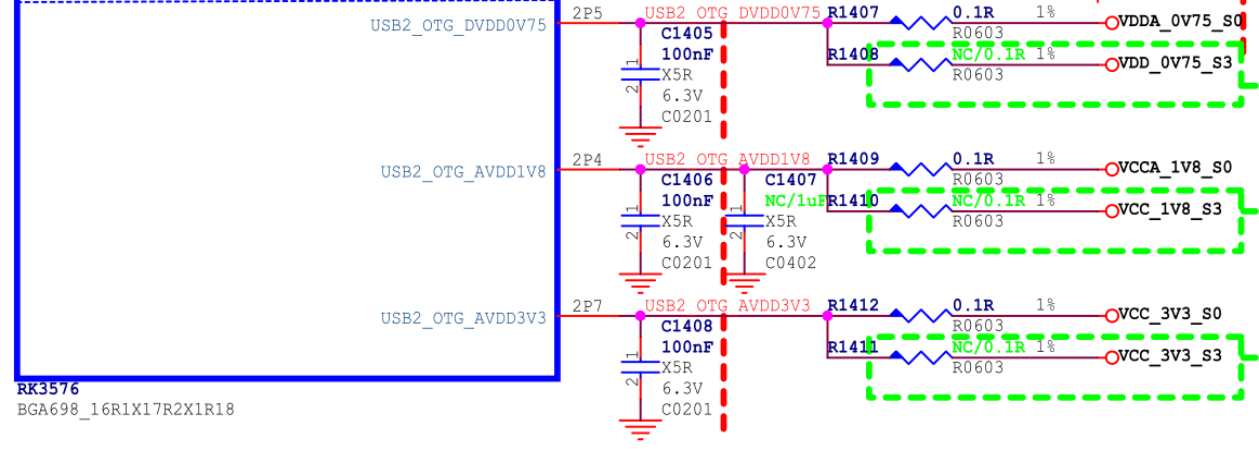
Abbildung 5: USB-2.0-PHY-Versorgung.
Spannungen oberhalb des angegebenen Maximums oder unterhalb des Minimums können USB-Verbindungsstörungen auslösen. Tabelle 3: Spannungsanforderungen des USB 2.0 PHY.
| Versorgungsspannung | Minimum | Normal | Maximum | Einheit |
|---|---|---|---|---|
| USB2_OTG_DVDD_0V75 | 0.6975 | 0.75 | 0.825 | V |
| USB2_OTG_AVDD_1V8 | 1.674 | 1.8 | 1.98 | V |
| USB2_OTG_AVDD_3V3 | 3.069 | 3.3 | 3.63 | V |
Strategie zur Verbrauchssteuerung des USB 2.0 PHY:
- Für Firmwareladen über Maskrom USB müssen alle drei PHY-Versorgungen normal anliegen.
- Nach Einschalten sind alle USB-2.0-PHYs im Normal-Modus. U-Boot SPL setzt USB 2.0 PHY1/PHY2/PHY3 in den sparsamsten IDDQ-Modus; dies ist bereits im SDK unterstützt. Nach Systemstart holt der Kernel-Treiber den benötigten PHY anwendungsabhängig aus IDDQ. Die Nummerierung entspricht dem Original.
- Für vom Kernel aktivierte PHYs steuert der Treiber den Verbrauch automatisch: erkanntes Gerät — Normal; kein Gerät — Suspend. Tabelle 4 enthält den Verbrauch eines einzelnen USB-2.0-PHYs in verschiedenen Zuständen.
| Versorgungsspannung | Lesen/Schreiben | Dynamischer Suspend | PHY deaktiviert | Standby zweiter Stufe | Einheit |
|---|---|---|---|---|---|
| USB20_DVDD_0V75 | 8.9 | 2.8 | 0.05 | 0 | mA |
| USB20_AVDD_1V8 | 8.6 | 3.34 | 0.05 | 0 | mA |
| USB20_AVDD_3V3 | 2.5 | 0.14 | 0.05 | 0 | mA |
Hinweise zu den Hersteller-Messszenarien:
- Lesen/Schreiben: Datenkopie mit U2-Datenträger, PHY in Normal.
- Dynamischer Suspend: PHY-DTS aktiviert, keine USB-Peripherie, PHY in Suspend.
- PHY disabled: DTS disabled, PHY in IDDQ.
- Standby der zweiten Stufe: Alle drei Versorgungen des USB 2.0 PHY sind abgeschaltet.
3.2.2 Versorgung und Verbrauchssteuerung der USB-3.1-PHYs
RK3576 unterstützt zwei USB-3.1-Combo-PHY-Arten:
- USB 3.1/DP Combo PHY.
- USB 3.1/PCIe/SATA Combo PHY. Versorgung und Verbrauchssteuerung unterscheiden sich und werden getrennt erläutert.
3.2.2.1 USB 3.1/DP Combo PHY
USB3.1 OTG0 verwendet den USB 3.1/DP Combo PHY. Intern gehört er zu VD_USBDPPHY (Alive); extern besitzt er die zwei unabhängigen Versorgungen in Abbildung 6.
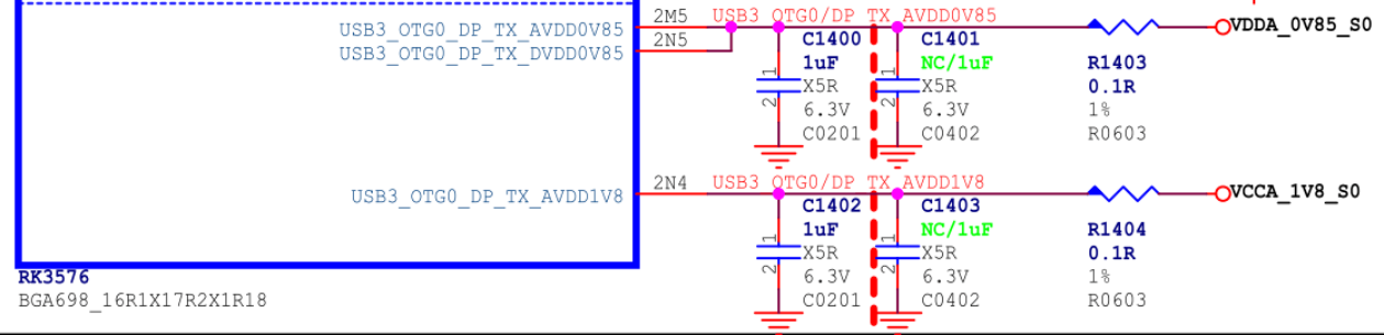
Abbildung 6: USBDP-Combo-PHY-Versorgung des RK3576. Tabelle 5: Spannungsanforderungen.
| Versorgung | Minimum | Normal | Maximum | Einheit |
|---|---|---|---|---|
| VDD_0V85/VDDA_0V85 | 0.8075 | 0.85 | 0.8925 | V |
| VDDH_1V8 | 1.71 | 1.8 | 1.89 | V |
Verbrauchsstrategie für USB 3.1/DP Combo PHY:
- Nach Einschalten ist USBDP PHY uninitialisiert und verbraucht am wenigsten.
- Bei USBDP-Nutzung regelt der Treiber dynamisch: Gerät erkannt — P0 State; kein Gerät — P3 State bei Type-A oder Reset bei Type-C.
- Werden weder USB3.1 noch DP genutzt, kann die Versorgung projektabhängig anliegen oder abgeschaltet sein. (1) Für USB3.1-Firmwareladen muss sie normal anliegen. (2) Wird diese Funktion nicht benötigt, wird empfohlen, die externe USBDP-Versorgung abzuschalten und DTS entsprechend dem Abschnitt ohne PHY-Versorgung zu ändern. (3) Wird kein USB3.1-Firmwareladen benötigt, bleibt aber Versorgung bestehen, sollte der USBDP-PHY-DTS-Knoten disabled sein: uninitialisiert mit minimalem Verbrauch. Tabelle 6: Verbrauch des USB 3.1/DP Combo PHY.
| Versorgung | Lesen/Schreiben | Dynamischer Schlaf | PHY deaktiviert | L2-Standby | Einheit |
|---|---|---|---|---|---|
| VDD_0V85/VDDA_0V85 | 101.6 | 5 | 2 | 0 | mA |
| VDDH_1V8 | 29 | 0 | 0 | 0 | mA |
Hinweise zu den Hersteller-Messszenarien:
- Lesen/Schreiben: Kopieren mit U3-Datenträger, PHY in P0.
- Dynamischer Schlaf: Type-C ohne USB-Gerät, PHY in Reset.
- PHY Disabled: DTS disabled, PHY uninitialisiert, minimaler Verbrauch.
- L2 Standby: Beide PHY-Versorgungen abgeschaltet. USBDP PHY im Kernel deaktivieren:
&usbdp_phy {
        status = "disabled";
};

&usbdp_phy_dp {
        status = "disabled";
};

&usbdp_phy_u3 {
        status = "disabled";
};
3.2.2.2 USB 3.1/PCIe/SATA Combo PHY
USB3.1 OTG1 verwendet USB3.1/PCIe/SATA Combo PHY1. Intern gehört dieser zu PD_BUS (Alive), extern besitzt er zwei unabhängige Versorgungen gemäß Abbildung 7.
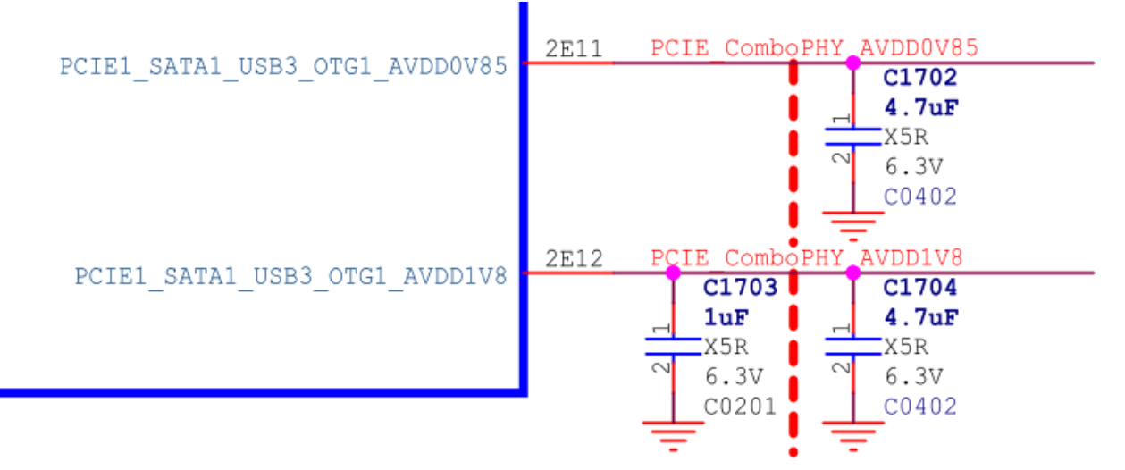
Abbildung 7: Versorgung des USB-3.1/PCIe/SATA-Combo-PHYs. Tabelle 7: Spannungsanforderungen.
| Versorgung | Minimum | Normal | Maximum | Einheit |
|---|---|---|---|---|
| AVDD_0V85 | 0.8 | 0.85 | 0.935 | V |
| AVDD_1V8 | 1.62 | 1.8 | 1.98 | V |
Verbrauchsstrategie für USB 3.1/PCIe/SATA Combo PHY:
- Beim Einschalten arbeitet der PHY standardmäßig. U-Boot SPL setzt ihn für minimalen Verbrauch in Reset. Im Kernel gibt der USB-Treiber den Reset durch rockchip_combphy_init() frei.
- Im USB-Modus steuert die Controller-Hardware PIPE P0/P1/P2/P3 abhängig vom Szenario. Ohne Gerät ist PIPE in P3; mit U3-Datenträger in P0. Bei angeschlossenem U3-HUB ohne nachgelagerte Peripherie geht PIPE automatisch in P3 zur Einsparung; mit Peripherie am HUB wieder in P0. P0 ist Normalbetrieb, P3 minimaler Verbrauch.
- Werden USB 3.1 OTG1/PCIe/SATA sicher nicht genutzt, kann Combo PHY unversorgt bleiben; DTS muss gemäß dem Abschnitt ohne PHY-Versorgung angepasst werden.
- Bei versorgtem, aber ungenutztem PHY dessen DTS-Knoten disabled setzen: Reset mit minimalem Verbrauch. Tabelle 8: Verbrauch des USB 3.1/SATA/PCIe Combo PHY.
| Versorgung | Lesen/Schreiben | Dynamischer Schlaf | PHY deaktiviert | Standby zweiter Stufe | Einheit |
|---|---|---|---|---|---|
| AVDD_0V85 | 44.5 | 9.6 | 0.4 | 0 | mA |
| AVDD_1V8 | 5.2 | 0.5 | 0.2 | 0 | mA |
Hinweise zu den Hersteller-Messszenarien:
- Lesen/Schreiben: U3-Datenträger, PHY in P0.
- Dynamischer Schlaf: DTS aktiviert, keine Peripherie, PHY in P3.
- PHY disabled: DTS disabled, PHY in Reset.
- Standby der zweiten Stufe: Beide Versorgungen abgeschaltet. Deaktivierung des Combo PHY im Kernel:
&combphy1_psu {
        status = "disabled";
};
3.3 USB-Hardwareschaltungen
3.3.1 Schaltung für USB2_OTG0_VBUSDET
USB2_OTG0_VBUSDET erkennt An- und Abstecken bei Device-Betrieb. Anforderungen:
- Bei Type-C mit PD und externem Controller wie FUSB302/HUSB311 die RK3576-EVB1-Type-C-Schaltung verwenden: USB2_OTG0_VBUSDET fest auf VCC_3V3_S0 ziehen. Der Treiber erkennt Device-Hotplug über CC-Pins des Type-C-Controllers.
- Ohne externen Type-C-Controller, etwa Type-C USB 2.0 only, Type-A USB 3.1 oder Micro USB 2.0/3.1, VBUSDET über den üblichen Spannungsteiler mit VBUS verbinden. Keine permanente Versorgung an VBUSDET. USB HOST benötigt separate GPIO- oder PMIC-VBUS-Steuerung, nicht gemeinsam mit anderen HOST-VBUS-Schaltungen.
- Geforderter High-Pegel an USB2_OTG0_VBUSDET: [0.9V ~ 3.3V].
3.3.2 Maskrom-USB-Schaltung
Maskrom unterstützt USB3.1-Firmwareladen und ist abwärtskompatibel zu USB2.0. Hardwareanforderungen:
- USB 2.0 PHY muss versorgt sein; siehe dessen Versorgungsabschnitt.
- USBDP PHY kann projektabhängig normal versorgt oder abgeschaltet sein; siehe USB-3.1-PHY-Abschnitt. Für USB3.1-Firmwareladen ist Versorgung Pflicht und USB3_OTG0_TX1/RX1 müssen zum Download-Port geführt werden.
- Maskrom-USB-Enumeration hängt nicht vom Pegel USB2_OTG0_VBUSDET ab.
- Flash-Werkzeug konfigurieren. (1) USB3.1-Firmwareladen benötigt Windows-Werkzeug v3.28 beziehungsweise Linux-Werkzeug v2.30 oder neuer. config.ini manuell ändern: Windows
USB3_TRANSFER=TRUE, Linuxusb3_transfer_on=true. (2) Bei OTG0 USB2-only ohne USBDP-PHY-Versorgung (USB3_OTG0_DP_TX_AVDD0V85, USB3_OTG0_DP_TX_DVDD0V85 und USB3_OTG0_DP_TX_AVDD1V8 aus) USB3 im Werkzeug deaktivieren; sonst scheitert Maskrom-Firmwareladen.
3.3.3 USB2-Schaltung mit System-Wakeup
USB2 kann über DP/DM aufwecken. Im Standby zweiter Stufe sind folgende Versorgungen erforderlich:
- Alle drei externen USB2-PHY-Versorgungen USB2_OTG_DVDD_0V75, USB2_OTG_AVDD_1V8 und USB2_OTG_AVDD_3V3 müssen anliegen.
- VBUS muss die USB-Peripherie weiter versorgen.
- Die externe OSC-Versorgung OSC_AVDD1V8 muss anliegen.
- Die externe PMU-Versorgung des RK3576 muss anliegen.
- Logic darf versorgt oder abgeschaltet sein; Abschalten wird für niedrigeren Standby-Verbrauch empfohlen.
3.3.4 Vollständige Type-C-USB-3.1/DP-Schaltung
Beispiel: RK3576 EVB1 USB 3.1 OTG0 Type-C.
- Für vollständiges Type-C mit Orientierungserkennung, PD-Ladeaushandlung und Alternate Mode ist ein externer Type-C-Controller erforderlich. RK3576 unterstützt die meisten gängigen Controller; siehe Unterstützungsliste.
- Für Hochvolt-Laden und geringeres Hardware-Risiko USB2_OTG0_VBUSDET nicht an Type-C-VBUS anschließen, sondern fest auf 3.3V ziehen: VCC_3V3_S0 in Abbildungen 8–9. Nicht offen lassen.
- USB2_OTG0_ID ist nur für Micro-OTG erforderlich; bei Type-C bleibt es unbeschaltet.
- TYPEC_SBU1/TYPEC0_SBU2 dienen nur der AUX-Kommunikation im DP Alternate Mode. AUX verlangt zur Type-C-Orientierung passende Pegel an SBU1/SBU2. RK3576 zieht diese intern nicht automatisch hoch, daher braucht die Schaltung zwei externe GPIO-Steuerungen (TYPEC_SBU1/TYPEC_SBU2 in Abbildung 9). Beliebige GPIOs sind möglich; ihre Standard-Pull-ups/-downs sind nicht vorgegeben. Softwareseitig
sbu1-dc-gpiosundsbu2-dc-gpiosim usbdp_phy-Knoten anpassen.
- DTS siehe vollständige Type-C-USB-3.1/DP-Konfiguration.
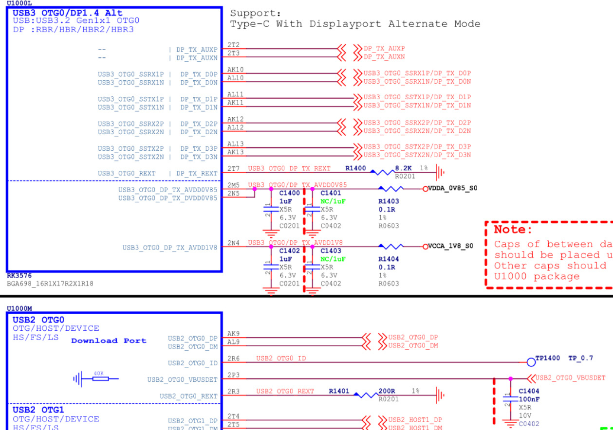
Abbildung 8: RK3576-Type-C-Schaltung.
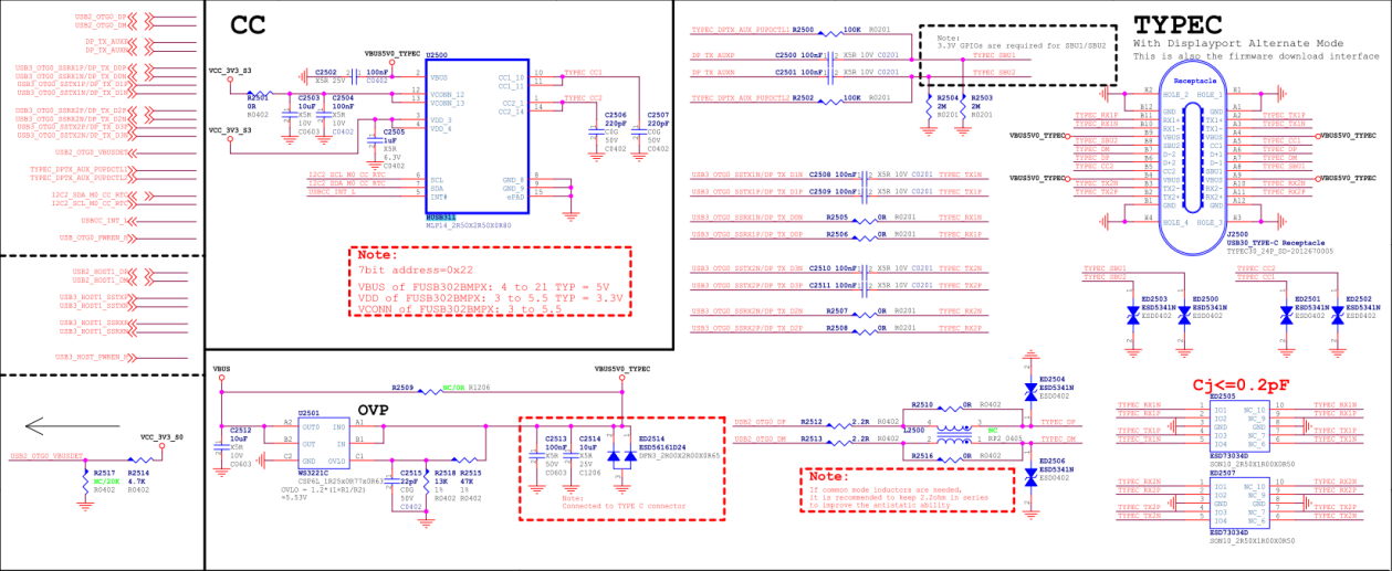
Abbildung 9: RK3576-Type-C-Schnittstelle.
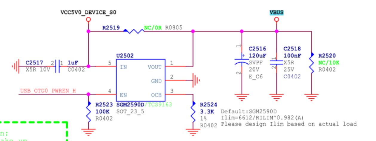
Abbildung 10: Type-C-VBUS-Steuerung.
3.3.5 Type-C-zu-Type-A-USB-3.1/DP-Schaltung
OTG0 Type-C lässt sich in einen unabhängigen Type-A-USB-3.1-Anschluss und DP mit zwei Lanes teilen. Beispiel: RK3576 EVB2.
- Type-A USB 3.1 nutzt USB3_OTG0_SSRX1P/N und USB3_OTG0_SSTX1P/N, entsprechend lane0/1 des internen USBDP PHY. DP nutzt DP_TX_D2P/N und DP_TX_D3P/N, entsprechend lane2/3.
- Bei Device/HOST-Nutzung USB2_OTG0_VBUSDET vorzugsweise über 30KΩ mit Type-A-VBUS verbinden.
- Type-A-VBUS (VCC5V0_USB30_HOST0) wird durch GPIO gesteuert: Device schaltet den Ausgang ab, HOST ein. Der Ausgangsstrom des SGM2590D hängt vom Widerstand am OCB-Pin ab. Maximalstrom Ilim(A) = 6612/RILIM^0.982; Abbildung 12 begrenzt VBUS auf 2.3A.
- DTS siehe Type-C zu Type-A USB 3.1/DP. Hinweis: Theoretisch können lane2/3 für USB3.1 und lane0/1 für DP genutzt werden; dann rockchip,dp-lane-mux im usbdp_phy-Knoten passend ändern.
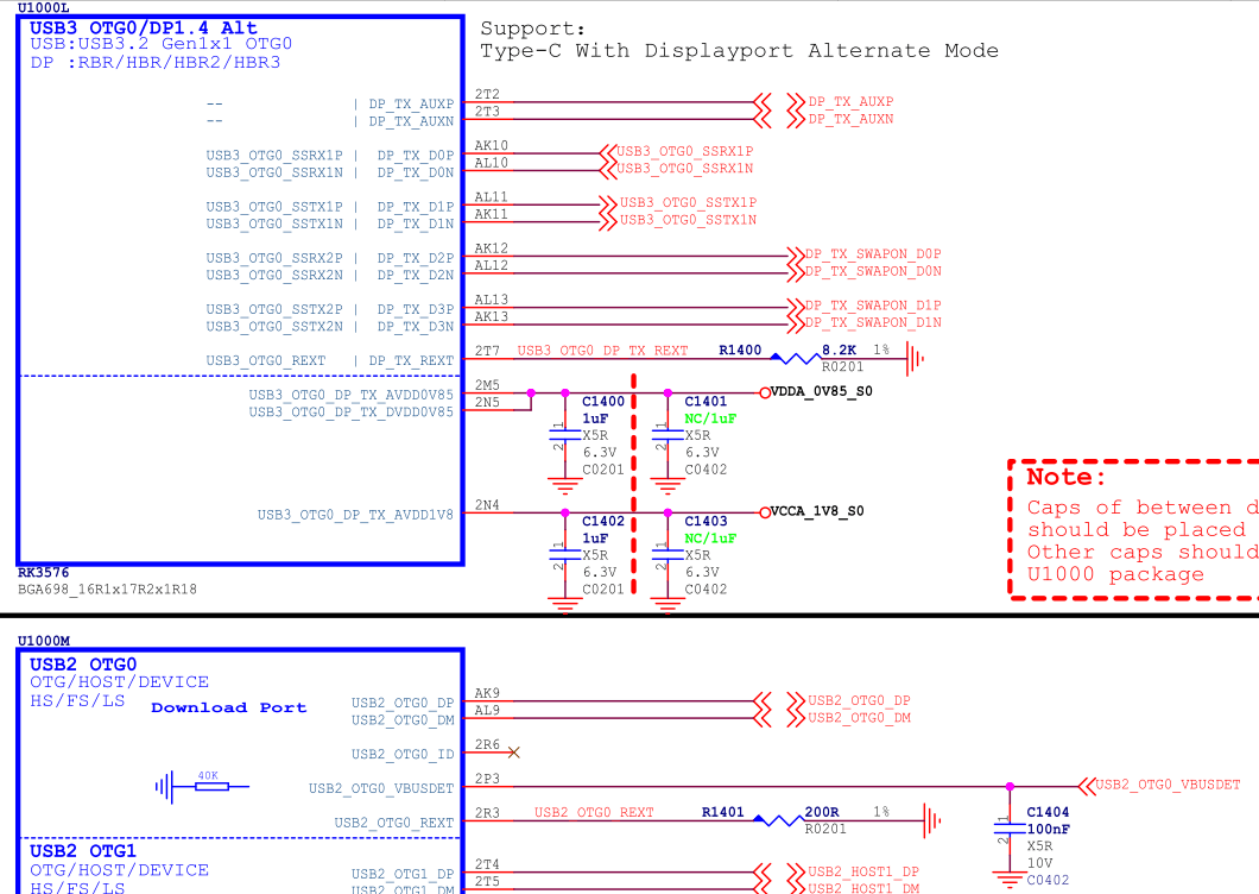
Abbildung 11: Type-A USB 3.1/DP des RK3576.
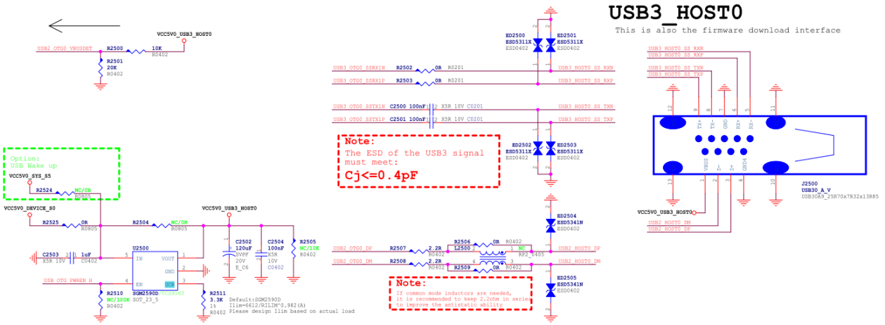
Abbildung 12: Type-A USB3.1 des RK3576.
3.3.6 Type-C zu Type-A/Micro USB 2.0/DP
OTG0 Type-C wird in unabhängiges Type-A USB 2.0 und DP mit vier Lanes geteilt. Beispiel ist die RK3576-TEST2-Board-Schaltung.
- Alle vier Lanes des TYPEC USBDP PHY dienen DP; USB nutzt den PHY nicht.
- Bei ausschließlichem HOST-Betrieb können USB2_OTG0_ID und USB2_OTG0_VBUSDET offen bleiben.
- Type-A-VBUS VCC5V0_USB2_OTG0 wird per GPIO im HOST-Modus eingeschaltet. SGM2590D bietet ebenfalls Strombegrenzung.
- DTS siehe Type-C zu Type-A/Micro USB 2.0/DP.
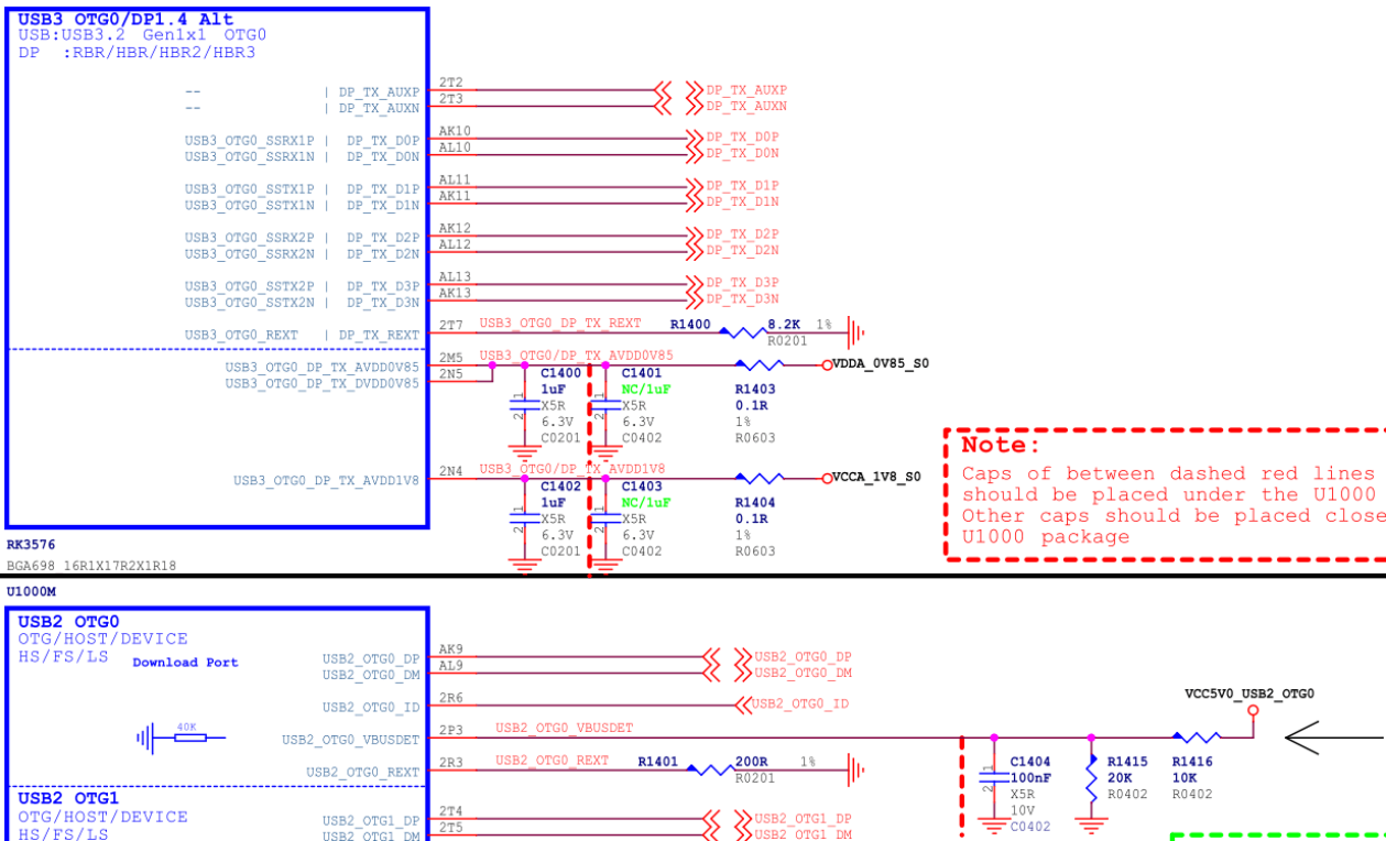
Abbildung 13: Type-A USB 2.0/DP des RK3576.
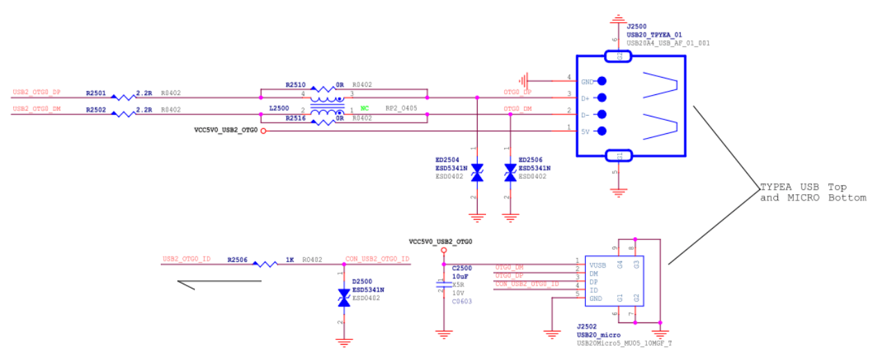
Abbildung 14: Type-A/Micro USB2 des RK3576.
3.3.7 Type-A USB3.1 OTG1
OTG0 und OTG1 unterscheiden sich vor allem durch den USB3-PHY. Ohne Type-C ist die OTG1-Schaltung daher im Wesentlichen gleich OTG0 USB3.1. Für vollständiges Type-C werden zwischen OTG1 und Anschluss zusätzlich ein USB3.1-Switch wie FUSB340 und ein Type-C-Controller wie FUSB302 benötigt.
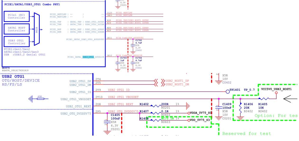
Abbildung 15: RK3576 USB3.1 OTG1.
4. RK3576 USB DTS
DTS umfasst chipweite Controller-/PHY-DTSI und platinenbezogene DTS. Details in diesen Kernel-Dokumenten:
kernel/Documentation/devicetree/bindings/usb/snps,dwc3.yaml
kernel/Documentation/devicetree/bindings/connector/usb-connector.yaml
kernel/Documentation/devicetree/bindings/phy/phy-rockchip-inno-usb2.yaml
kernel/Documentation/devicetree/bindings/phy/phy-rockchip-usbdp.yaml
kernel/Documentation/devicetree/bindings/phy/phy/phy-rockchip-naneng-combphy.txt(Quellpfad).
4.1 Chipweite USB-DTSI
Die Tabelle enthält die wesentlichen Controller-/PHY-Knoten. Da sie gemeinsame Ressourcen und Eigenschaften definieren, werden Änderungen durch Entwickler nicht empfohlen. Quellpfad: arch/arm64/boot/dts/rockchip/RK3576.dtsi. Tabelle 9: USB-Schnittstellen und DTS-Knoten.
| USB-Schnittstelle (Schaltplan) | USB-Controller-DTS-Knoten | USB-PHY-DTS-Knoten |
|---|---|---|
| USB3 OTG0 | usb_drd0_dwc3 | u2phy0 u2phy0_otg usbdp_phy usbdp_phy_u3 |
| USB3 OTG1 | usb_drd1_dwc3 | u2phy1 u2phy1_otg combphy1_psu |
USB-Controller-DTSI-Knoten:
#USB3.1 OTG0 Controller
usb_drd0_dwc3: usb@23000000 {
        compatible = "rockchip,rk3576-dwc3", "snps,dwc3";
        ......
};

#USB3.1 OTG1 Controller
usb_drd1_dwc3: usb@23400000 {
        compatible = "rockchip,rk3576-dwc3", "snps,dwc3";
        ......
};
USB-PHY-DTSI-Knoten. PHY und Controller entsprechen einander und sind paarweise zu konfigurieren. Interne Verbindungen siehe Abbildung 1 und Tabelle 9; die Controller-Eigenschaft phys verweist auf den zugehörigen PHY.
usb2phy_grf: syscon@2602e000 {
        compatible = "rockchip,RK3576-usb2phy-grf", "syscon",
                     "simple-mfd";
        ......

        // USB2.0 PHY0
        u2phy0: usb2-phy@0 {
                compatible = "rockchip,RK3576-usb2phy";
                ......
                u2phy0_otg: otg-port {
                        #phy-cells = <0>;
                        status = "disabled";
                };
        };

        // USB2.0 PHY1
        u2phy1: usb2-phy@2000 {
                compatible = "rockchip,RK3576-usb2phy";
                ......
                u2phy1_otg: otg-port {
                        #phy-cells = <0>;
                        status = "disabled";
                };
        };
};

#USB3.1/DP Combo PHY
usbdp_phy: phy@2b010000 {
        compatible = "rockchip,rk3576-usbdp-phy";
        ......
        usbdp_phy_dp: dp-port {
                #phy-cells = <0>;
                status = "disabled";
        };

        usbdp_phy_u3: u3-port {
                #phy-cells = <0>;
                status = "disabled";
        };
};

#USB3.1/SATA/PCIe PHY1
combphy1_psu: phy@2b060000 {
        compatible = "rockchip,rk3576-naneng-combphy";
        ......
};
4.2 Vollständiges USB 3.1/DP DTS
Siehe usbc0 in arch/arm64/boot/dts/rockchip/rk3576-evb1.dtsi.
// USB2.0 PHY Configuration Property "rockchip,typec-vbus-det", indicating support for
hardware designs with Type-C VBUS_DET constantly pulled high
&u2phy0_otg {
        rockchip,typec-vbus-det;
};

// USB3.1/DP PHY, configure properties "sbu1-dc-gpios" and "sbu2-dc-gpios" according to
hardware design
&usbdp_phy {
        orientation-switch;
        svid = <0xff01>;
        sbu1-dc-gpios = <&gpio2 RK_PA6 GPIO_ACTIVE_HIGH>;
        sbu2-dc-gpios = <&gpio2 RK_PA7 GPIO_ACTIVE_HIGH>;

        port {
                #address-cells = <1>;
                #size-cells = <0>;
                usbdp_phy_orientation_switch: endpoint@0 {
                        reg = <0>;
                        remote-endpoint = <&usbc0_orien_sw>;
                };

                usbdp_phy_dp_altmode_mux: endpoint@1 {
                        reg = <1>;
                        remote-endpoint = <&dp_altmode_mux>;
                };
        };
};

// USB3.1 OTG0 Controller
&usb_drd0_dwc3 {
        dr_mode = "otg";
        usb-role-switch;
        port {
                usb_drd0_role_switch: endpoint {
                        remote-endpoint = <&usbc0_role_sw>;
                };
        };
};

// VBUS GPIO Configuration, controlled by the Type-C controller chip driver
vbus5v0_typec: vbus5v0-typec {
        compatible = "regulator-fixed";
        regulator-name = "vbus5v0_typec";
        regulator-min-microvolt = <5000000>;
        regulator-max-microvolt = <5000000>;
        enable-active-high;
        gpio = <&gpio0 RK_PD1 GPIO_ACTIVE_HIGH>;
        vin-supply = <&vcc5v0_device>;
        pinctrl-names = "default";
        pinctrl-0 = <&usb_otg0_pwren>;
};

// Configure external Type-C controller chip HUSB311
// Configure properties "I2C/interrupts/vbus-supply/usb_con" according to actual hardware
design
&i2c2 {
        status = "okay";

        usbc0: husb311@4e {
                compatible = "hynetek,husb311"; // Note 1
                reg = <0x4e>;
                interrupt-parent = <&gpio0>;
                interrupts = <RK_PA5 IRQ_TYPE_LEVEL_LOW>;
                pinctrl-names = "default";
                pinctrl-0 = <&usbc0_int>;
                vbus-supply = <&vbus5v0_typec>;
                status = "okay";

                port {
                        usbc0_role_sw: endpoint {
                                remote-endpoint = <&usb_drd0_role_switch>;
                        };
                };

                usb_con: connector {
                        compatible = "usb-c-connector";
                        label = "USB-C";
                        data-role = "dual";
                        power-role = "dual";
                        try-power-role = "sink";
                        op-sink-microwatt = <1000000>;

                        // Configure charging/supplying capability according to actual
hardware design
                        sink-pdos =
                                <PDO_FIXED(5000, 1000, PDO_FIXED_USB_COMM)>;
                        source-pdos =
                                <PDO_FIXED(5000, 3000, PDO_FIXED_USB_COMM)>;

                        altmodes {
                                #address-cells = <1>;
                                #size-cells = <0>;

                                altmode@0 {
                                        reg = <0>;
                                        svid = <0xff01>;
                                        vdo = <0xffffffff>;
                                };
                        };
                        ports {
                                #address-cells = <1>;
                                #size-cells = <0>;

                                port@0 {
                                        reg = <0>;
                                        usbc0_orien_sw: endpoint {
                                                remote-endpoint =
<&usbdp_phy_orientation_switch>;
                                        };
                                };

                                port@1 {
                                        reg = <1>;
                                        dp_altmode_mux: endpoint {
                                                remote-endpoint =
<&usbdp_phy_dp_altmode_mux>;
                                        };
                                };
                        };
                };
        };
};
Hinweis: HUSB311 durch FUSB302/AW35615/AW35615 ersetzen; die AW35615-Dopplung stammt aus der Quelle.
- DTS: Die folgenden kleinen Anpassungen an der HUSB311-Konfiguration reichen aus.
// Configure external Type-C controller chip HUSB311
&i2c2 {
        usbc0: fusb302@22 {
                compatible = "fcs,fusb302";
                reg = <0x22>;
                ...... // The rest is the same as HUSB311
        };
};
- Treiber: Den irq-wakeup-Mechanismus von FUSB302 für Standby mit abgeschaltetem oder anliegendem VBUS anpassen.
diff --git a/drivers/usb/typec/tcpm/fusb302.c b/drivers/usb/typec/tcpm/fusb302.c
index 77a050cd2e88..72bef94887b4 100644
--- a/drivers/usb/typec/tcpm/fusb302.c
+++ b/drivers/usb/typec/tcpm/fusb302.c
@@ -105,6 +105,7 @@ struct fusb302_chip {
        bool vbus_on;
        bool charge_on;
        bool vbus_present;
+       bool wakeup;
        enum typec_cc_polarity cc_polarity;
        enum typec_cc_status cc1;
        enum typec_cc_status cc2;
@@ -1769,7 +1770,8 @@ static int fusb302_probe(struct i2c_client *client,
                dev_err(dev, "cannot request IRQ for GPIO Int_N, ret=%d", ret);
                goto tcpm_unregister_port;
        }
-       enable_irq_wake(chip->gpio_int_n_irq);
+       chip->wakeup = device_property_read_bool(dev, "wakeup-source");
+       device_init_wakeup(dev, true);
        i2c_set_clientdata(client, chip);

        return ret;
@@ -1788,7 +1790,7 @@ static void fusb302_remove(struct i2c_client *client)
 {
        struct fusb302_chip *chip = i2c_get_clientdata(client);

-       disable_irq_wake(chip->gpio_int_n_irq);
+       device_init_wakeup(chip->dev, false);
        free_irq(chip->gpio_int_n_irq, chip);
        kthread_destroy_worker(chip->irq_worker);
        cancel_delayed_work_sync(&chip->bc_lvl_handler);
@@ -1809,6 +1811,11 @@ static int fusb302_pm_suspend(struct device *dev)

        /* Make sure any pending irq_work is finished before the bus suspends */
        kthread_flush_worker(chip->irq_worker);
+
+       if (device_may_wakeup(dev) && (!chip->vbus_on || chip->wakeup))
+               enable_irq_wake(chip->gpio_int_n_irq);
+       else
+               disable_irq(chip->gpio_int_n_irq);
        return 0;
 }

@@ -1819,6 +1826,11 @@ static int fusb302_pm_resume(struct device *dev)
        u8 pwr;
        int ret = 0;

+       if (device_may_wakeup(dev) && (!chip->vbus_on || chip->wakeup))
+               disable_irq_wake(chip->gpio_int_n_irq);
+       else
+               enable_irq(chip->gpio_int_n_irq);
+
        /*
         * When the power of fusb302 is lost or i2c read failed in PM S/R
         * process, we must reset the tcpm port first to ensure the devices
4.3 DTS für Type-C zu Type-A USB 3.1/DP
Siehe arch/arm64/boot/dts/rockchip/RK3576-evb2.dtsi.
#USB2.0 PHY configuration for "phy-supply" attribute, used to control VBUS output at 5V
&u2phy0_otg {
        phy-supply = <&vcc5v0_otg>;
};

#VBUS GPIO configuration, controlled by this GPIO in the USB2.0 PHY driver
vcc5v0_otg: vcc5v0-otg {
        compatible = "regulator-fixed";
        regulator-name = "vcc5v0_otg";
        regulator-min-microvolt = <5000000>;
        regulator-max-microvolt = <5000000>;
        enable-active-high;
        gpio = <&gpio0 RK_PD1 GPIO_ACTIVE_HIGH>;
        vin-supply = <&vcc5v0_device>;
        pinctrl-names = "default";
        pinctrl-0 = <&usb_otg0_pwren>;
};

#USB3.1/DP PHY0, configure DP to use lane2/3, the driver will automatically allocate lane0/1
for USB3.1 Rx/Tx
#If the hardware design uses DP on lane0/1, then "rockchip,dp-lane-mux = <0 1>" should be
configured here
#Note: Even if DP is not supported in the actual circuit, "rockchip,dp-lane-mux" must be
configured, otherwise the USBDP PHY driver cannot automatically allocate lanes to USB3.1
&usbdp_phy {
        rockchip,dp-lane-mux = <2 3>;
};

#USB3.1 OTG0 Controller
#Set "dr_mode" to "otg" and configure the "extcon" attribute to support software switching
between Device/Host mode
&usb_drd0_dwc3 {
        dr_mode = "otg";
        extcon = <&u2phy0>;
        status = "okay";
};
4.4 DTS für Type-C zu Type-A/Micro USB 2.0/DP
Siehe arch/arm64/boot/dts/rockchip/RK3576-test2.dtsi.
# USB2.0 PHY0 Configuration
# Configure the property "phy-supply" to control the VBUS output of 5V
# Configure the property "rockchip,sel-pipe-phystatus", indicating the selection of GRF to
control the pipe phystatus, replacing the control of USBDP PHY
# Configure the property "rockchip,dis-u2-susphy", where otg mode is an option, indicating
the function to close the USB2 PHY driver dynamically entering suspend mode is optional
&u2phy0_otg {
        vbus-supply = <&vcc5v0_otg>;
        rockchip,sel-pipe-phystatus;
        rockchip,dis-u2-susphy;
        status = "okay";
};

# VBUS GPIO Configuration, controlling this GPIO in the USB2.0 PHY driver
vcc5v0_otg: vcc5v0-otg {
        ...
};

# USB3.1/DP PHY, configure DP to use lanes 0/1/2/3
# According to the actual hardware design, configure the property "rockchip,dp-lane-mux"
# Configure the property maximum-speed = "high-speed", to notify the USBDP PHY driver to
restrict USB to USB2.0 only
&usbdp_phy {
        maximum-speed = "high-speed";
        rockchip,dp-lane-mux = < 0 1 2 3 >;
        status = "okay";
};

&usbdp_phy_dp {
        status = "okay";
};

&usbdp_phy_u3 {
        status = "okay";
};

# Configure the property "maximum-speed", to notify the DWC3 driver to restrict USB to
USB2.0 only
# Configure the property "snps,dis_u2_susphy_quirk", to disable the controller hardware's
suspend usb2 phy function, improving the stability of USB communication
# Configure the property "snps,usb2-lpm-disable", to disable the controller's Host mode LPM
function, improving the compatibility of USB peripherals
&usb_drd0_dwc3 {
        phys = <&u2phy0_otg>;
        phy-names = "usb2-phy";
        extcon = <&u2phy0>;
        maximum-speed = "high-speed";
        snps,dis_u2_susphy_quirk;
        snps,usb2-lpm-disable;
        status = "okay";
};
4.5 DTS für Type-C USB 2.0 only
Variante 1: Externer Type-C-Controller in der Schaltung, PD unterstützt.
#USB2.0 PHY0 registers typec orientation switch, used for interaction with the TCPM
subsystem, to obtain USB hot-plug information
&u2phy0 {
        orientation-switch;
        status = "okay";

        port {
                u2phy0_orientation_switch: endpoint {
                        remote-endpoint = <&usbc0_orien_sw>;
                };
        };
};

#USB2.0 PHY0 OTG configuration
#Configuration property "rockchip,sel-pipe-phystatus", indicates the selection of GRF
control pipe phystatus, replacing the control of USBDP PHY
#Configuration property "rockchip,typec-vbus-det", indicates support for Type-C VBUS_DET
hardware designs that are always pulled high
#Configuration property "rockchip,dis-u2-susphy", optional, indicates disabling the USB2 PHY
driver's dynamic entry into suspend mode function
&u2phy0_otg {
        rockchip,sel-pipe-phystatus;
        rockchip,typec-vbus-det;
        rockchip,dis-u2-susphy;
        status = "okay";
};

#Configure the USBDP CombPHY parent node
#Note: The usbdp_phy node must be correctly configured according to whether the actual
hardware circuit USBDP CombPHY is powered.
#Case 1. If the actual hardware circuit CombPHY is designed to be powered, then disable all
relevant parent nodes and child nodes of usbdp_phy, keeping the USBDP PHY in an
uninitialized state to achieve the lowest power consumption
&usbdp_phy {
        status = "disabled";
};
#Case 2. If the actual hardware circuit CombPHY is not powered, then enable the usbdp_phy
node and disable related child nodes to prevent system startup exceptions or USB download
function exceptions
&usbdp_phy {
        rockchip,usbdpphy-clamp; /* To avoid power-off affecting bus access and Logic
leakage to USBDP PHY */
        maximum-speed = "high-speed"; /* Limit u2 only, to avoid initializing USBDP PHY */
        status = "okay";
};

#Configure the USBDP CombPHY child nodes
&usbdp_phy_dp {
        status = "disabled";
};

&usbdp_phy_u3 {
        status = "disabled";
};

#Configure the DP controller
&dp {
        status = "disabled";
};

#Configure the USB3.1 OTG0 Controller
#Configure "phys = <&u2phy0_otg>", which means not to reference the USBDP PHY
#Configure maximum-speed = "high-speed", to inform the DWC3 driver to limit USB to USB2.0
only
#Configuration property "snps,dis_u2_susphy_quirk", to disable the controller's hardware
suspend usb2 phy function, improving the stability of USB communication
#Configuration property "snps,usb2-lpm-disable", to disable the controller's Host mode LPM
function, improving the compatibility of USB peripherals
&usb_drd0_dwc3 {
        dr_mode = "otg";
        status = "okay";
        maximum-speed = "high-speed";
        phys = <&u2phy0_otg>;
        phy-names = "usb2-phy";
        usb-role-switch;
        snps,dis_u2_susphy_quirk;
        snps,usb2-lpm-disable;
        port {
                usb_drd0_role_switch: endpoint {
                        remote-endpoint = <&usbc0_role_sw>;
                };
        };
};

#Configure the external Type-C controller chip HUSB311
#Properties "I2C/interrupts/vbus-supply/usb_con" must be configured according to the actual
hardware design
#The property usbc0_orien_sw's remote-endpoint must be set to <&u2phy0_orientation_switch>
&i2c2 {
        status = "okay";
        usbc0: husb311@4e {
                compatible = "hynetek,husb311";
                reg = <0x4e>;
                interrupt-parent = <&gpio0>;
                interrupts = <RK_PC4 IRQ_TYPE_LEVEL_LOW>;
                pinctrl-names = "default";
                pinctrl-0 = <&usbc0_int>;
                vbus-supply = <&vbus5v0_typec>;
                status = "okay";

                port {
                usbc0_role_sw: endpoint {
                        remote-endpoint = <&usb_drd0_role_switch>;
                };
        };

        usb_con: connector {
                compatible = "usb-c-connector";
                label = "USB-C";
                data-role = "dual";
                power-role = "dual";
                ......
                port {
                        usbc0_orien_sw: endpoint {
                                remote-endpoint = <&u2phy0_orientation_switch>;
                        };
                };
        };
};
Variante 2: Ohne externen Type-C-Controller, nur Device. DTS für Type-C USB 2.0 Device:
#USB2.0 PHY0 OTG configuration
#Configuration property "rockchip,sel-pipe-phystatus", indicates the selection of GRF
control pipe phystatus, replacing the control of USBDP PHY
#Configuration property "rockchip,dis-u2-susphy", a required option, indicates disabling the
USB2 PHY driver's dynamic entry into suspend mode function
&u2phy0_otg {
        rockchip,sel-pipe-phystatus;
        rockchip,dis-u2-susphy;
        status = "okay";
};

#Configure the USBDP CombPHY parent node
#Note: The usbdp_phy node must be correctly configured according to whether the actual
hardware circuit USBDP CombPHY is powered.
#Case 1. If the actual hardware circuit CombPHY is designed to be powered, then disable all
relevant parent nodes and child nodes of usbdp_phy, keeping the USBDP PHY in an
uninitialized state to achieve the lowest power consumption
&usbdp_phy {
        status = "disabled";
};
#Case 2. If the actual hardware circuit CombPHY is not powered, then enable the usbdp_phy
node and disable related child nodes to prevent system startup exceptions or USB download
function exceptions
&usbdp_phy {
        rockchip,usbdpphy-clamp; /* To avoid power-off affecting bus access and Logic
leakage to USBDP PHY */
        maximum-speed = "high-speed"; /* Limit u2 only, to avoid initializing USBDP PHY */
        status = "okay";
};
#Configure the USBDP CombPHY child nodes
&usbdp_phy_dp {
        status = "disabled";
};

&usbdp_phy_u3 {
        status = "disabled";
};

#Configure the DP controller
&dp {
        status = "disabled";
};

#Configure the USB3.1 OTG0 Controller
#Configure dr_mode = "peripheral", to inform the DWC3 driver to initialize in Device only
mode
#Configure "phys = <&u2phy0_otg>", which means not to reference the USBDP PHY
#Configure maximum-speed = "high-speed", to inform the DWC3 driver to limit USB to USB2.0
only
#Configuration property "snps,dis_u2_susphy_quirk", to disable the controller's hardware
suspend usb2 phy function, improving the stability of USB communication
&usb_drd0_dwc3 {
        dr_mode = "peripheral";
        phys = <&u2phy0_otg>;
        phy-names = "usb2-phy";
        maximum-speed = "high-speed";
        snps,dis_u2_susphy_quirk;
        status = "okay";
};
Variante 3: Ohne externen Type-C-Controller, OTG unterstützt; CC-zu-ID-Pegelwandlerschaltung erforderlich.
#USB2.0 PHY0 OTG configuration
#Configuration property "rockchip,sel-pipe-phystatus", indicates the selection of GRF
control pipe phystatus, replacing the control of USBDP PHY
#Configuration property "rockchip,dis-u2-susphy", otg mode is an optional, indicates
disabling the USB2 PHY driver's dynamic entry into suspend mode function
&u2phy0_otg {
        rockchip,sel-pipe-phystatus;
        rockchip,dis-u2-susphy;
        status = "okay";
};

#Configure the USBDP CombPHY parent node
#Note: The usbdp_phy node must be correctly configured according to whether the actual
hardware circuit USBDP CombPHY is powered.
#Case 1. If the actual hardware circuit CombPHY is designed to be powered, then disable the
parent node and child nodes of usbdp_phy, keeping the USBDP PHY in an uninitialized state to
achieve the lowest power consumption
&usbdp_phy {
        status = "disabled";
};
#Case 2. If the actual hardware circuit CombPHY is not powered, then enable the usbdp_phy
node and disable related child nodes to prevent system startup exceptions or USB download
function exceptions
&usbdp_phy {
        rockchip,usbdpphy-clamp; /* To avoid power-off affecting bus access and Logic
leakage to USBDP PHY */
        maximum-speed = "high-speed"; /* Limit u2 only, to avoid initializing USBDP PHY */
        status = "okay";
};

#Configure the USBDP CombPHY child nodes
&usbdp_phy_dp {
        status = "disabled";
};

&usbdp_phy_u3 {
        status = "disabled";
};

#Configure the DP controller
&dp {
        status = "disabled";
};

#Configure the USB3.1 OTG0 Controller
#Configure dr_mode = "otg"
#Configure "phys = <&u2phy0_otg>", which means not to reference the USBDP PHY
#Configure maximum-speed = "high-speed", to inform the DWC3 driver to limit USB to USB2.0
only
#Configure "extcon" property, to support automatic switching between Device/Host mode
#Configuration property "snps,dis_u2_susphy_quirk", to disable the controller's hardware
suspend usb2 phy function, improving the stability of USB communication
#Configuration property "snps,usb2-lpm-disable", to disable the controller's Host mode LPM
function, improving the compatibility of USB peripherals
&usb_drd0_dwc3 {
        dr_mode = "otg";
        phys = <&u2phy0_otg>;
        phy-names = "usb2-phy";
        maximum-speed = "high-speed";
        extcon = <&u2phy0>;
        snps,dis_u2_susphy_quirk;
        snps,usb2-lpm-disable;
        status = "okay";
};
4.6 Type-A USB 3.1 DTS
Siehe USB3 OTG1 in arch/arm64/boot/dts/rockchip/rk3576-evb1.dtsi.
#USB2.0 PHY1 configuration for "phy-supply" attribute to control VBUS output at 5V
&u2phy1_otg {
        phy-supply = <&vcc5v0_host>;
}

#VBUS GPIO configuration to control this GPIO in the USB2.0 PHY driver
vcc5v0_host: vcc5v0-host {
        compatible = "regulator-fixed";
        regulator-name = "vcc5v0_host";
        regulator-boot-on;
        regulator-always-on;
        regulator-min-microvolt = <5000000>;
        regulator-max-microvolt = <5000000>;
        enable-active-high;
        gpio = <&gpio0 RK_PC7 GPIO_ACTIVE_HIGH>;
        vin-supply = <&vcc5v0_device>;
        pinctrl-names = "default";
        pinctrl-0 = <&vcc5v0_host_en>;
};

#Enable USB3.1/SATA/PCIe Combo PHY
&combphy1_psu {
        status = "okay";
};

#Configure USB3.1 OTG1 Controller
&usb_drd1_dwc3 {
        dr_mode = "host";
        status = "okay";
};
4.7 DTS ohne USB-PHY-Versorgung
USBDP PHY (OTG0 USB3.1/DP) und ComboPHY1 (OTG1 USB3.1/PCIe1/SATA1) dürfen extern unversorgt bleiben, um Verbrauch zu senken und die Hardware zu vereinfachen. Entsprechende DTS-Anpassung ist Pflicht, sonst drohen Startfehler oder USB-Störungen.
4.7.1 USBDP PHY ohne Versorgung
&usbdp_phy {
        rockchip,usbdpphy-clamp; /* Prevent power-off from affecting bus access and Logic
leakage to USBDP PHY */
        maximum-speed = "high-speed"; /* Restrict u2 only, to avoid initializing USBDP PHY
*/
        status = "okay";
};

&usbdp_phy_dp {
        status = "disabled";
};

&usbdp_phy_u3 {
        status = "disabled";
};
Kernel-Aktivierungslog:
rockchip-usbdp-phy 2b010000.phy: Failed to enable usbdpphy because clamp is set
rockchip-usbdp-phy: probe of 2b010000.phy failed with error -95
Auch USB3-Download im Flash-Werkzeug abschalten, sonst scheitert Maskrom. Windows config.ini: USB3_TRANSFER=FALSE; Linux config.ini: usb3_transfer_on=false.
4.7.2 ComboPHY1 ohne Versorgung
ComboPHY1 dient OTG1 USB3.1, beeinflusst aber auch den SoC-Buszugriff von OTG1 USB2. DTS hängt daher davon ab, ob USB2.0 benötigt wird.
- USB3.1 OTG1 ungenutzt, USB2.0 erforderlich.
&combphy1_psu {
        rockchip,dis-u3otg1-port;
        status = "okay";
};

&usb_drd1_dwc3 {
        dr_mode = "host";
        phys = <&u2phy1_otg>, <&combphy1_psu PHY_TYPE_USB3>;  /* This must reference
combphy1_psu */
        phy-names = "usb2-phy", "usb3-phy";
        maximum-speed = "high-speed";
        snps,dis_u2_susphy_quirk;
        snps,usb2-lpm-disable;
        status = "okay";
};
- Weder USB2.0 noch USB3.1 OTG1 genutzt.
&combphy1_psu {
        status = "disabled";
};

&usb_drd1_dwc3 {
        status = "disabled";
};
4.8 Hinweise zu Linux USB DT
4.8.1 Wichtige USB-DT-Eigenschaften
4.8.1.1 USB-Controller
- usb-role-switch ist nur für Standard-Type-C mit PD-Controller vorgesehen; dr_mode muss otg sein. Bei anderem dr_mode nicht konfigurieren.
- extcon schaltet OTG dynamisch in Nicht-Standard-Type-C-Schaltungen (der Originaltext erwähnt einen PD-Controller), etwa Micro oder Type-A, wenn der Controller im otg-Modus konfiguriert ist.
- snps,dis_u2_susphy_quirk deaktiviert das automatische Hardware-Suspend des USB2 PHY durch den Controller, vor allem für stabilere USB2-only-Kommunikation.
- snps,usb2-lpm-disable deaktiviert Host-LPM, vor allem für bessere Peripheriekompatibilität bei USB2-only.
4.8.1.2 USB2-PHY-Eigenschaften
- vbus-supply und phy-supply steuern 5V-VBUS: vbus-supply für dynamisch schaltendes OTG; phy-supply für USB HOST mit dauerhaftem 5V-VBUS nach Systemstart.
- rockchip,sel-pipe-phystatus konfiguriert das GRF-USB-Steuerregister, sodass GRF statt USBDP PHY pipe phystatus steuert. Bei USB2-only ohne aktivierten USBDP PHY ist es zwingend, sonst arbeitet USB nicht korrekt.
- rockchip,typec-vbus-det unterstützt Schaltungen mit dauerhaft hochgezogenem Type-C VBUS_DET.
- rockchip,dis-u2-susphy verhindert den dynamischen Suspend im USB2-PHY-Treiber; hauptsächlich für USB2-only, damit der PHY-Ausgangstakt zum Controller erhalten bleibt.
4.8.1.3 USBDP-Combo-PHY-Eigenschaften
- rockchip,dp-lane-mux legt DP-Lanes in nicht vollständigen Type-C-Lösungen fest. DP unterstützt zwei oder vier Lanes.
rockchip,dp-lane-mux = <2, 3>;ordnet DP Lane0 PHY Lane2 und DP Lane1 PHY Lane3 zu.<0, 1, 2, 3>bedeutet direkte Zuordnung. Auch bei ausschließlich USB3.1 ohne DP ist diese Eigenschaft Pflicht, sonst kann der Treiber keine USB3.1-Lanes automatisch zuweisen.
maximum-speed = "high-speed";begrenzt USB im USBDP-PHY-Treiber auf USB2.0; im Elternknoten usbdp_phy konfigurieren.
4.8.1.4 USBC-Eigenschaften
- usbc ist gewöhnlich i2c-Kindknoten. Neben compatible und reg gibt es port und connector. port beschreibt role switch mit dem USB-Controller; connector enthält PD-Grundeigenschaften sowie altmodes und ports für orientation switch und altmode mux.
- sink-pdos und source-pdos definieren im connector Spannungs-/Stromstufen und weitere Leistungsfähigkeiten des RK3576 als Sink beziehungsweise Source. Sie müssen zur Lade-IC passen. Felder müssen PD Spec entsprechen; wichtige Felder verwenden Makros aus
include/dt-bindings/usb/pd.h.
5. USB-OTG-Umschaltbefehle des RK3576
Das SDK erzwingt Host/Peripheral softwareseitig unabhängig von OTG-ID-Pin oder Type-C. Linux-6.1 bietet zwei Methoden. Methode 1 benötigt korrektes USB DTS und gilt nur ohne Type-C; Methode 2 hat diese Einschränkungen nicht. Bei unklarer Hardware-/Softwareanpassung empfiehlt die Quelle Methode 2. Methode 1 [Legacy]:
#1.Force host mode
  echo host > /sys/devices/platform/2602e000.syscon/2602e000.syscon:usb2-phy@0/otg_mode
#2.Force peripheral mode
  echo peripheral > /sys/devices/platform/2602e000.syscon/2602e000.syscon:usb2-
phy@0/otg_mode
Methode 2 [New]:
#1.Force host mode
  echo host > /sys/kernel/debug/usb/23000000.usb/mode
#2.Force peripheral mode
  echo device > /sys/kernel/debug/usb/23000000.usb/mode
6. Unterstützte Type-C-Controller
Tabelle 17: Unterstützte Type-C-Controller.
| Type-C-Controllermodell | Linux-6.1 | Beschreibung |
|---|---|---|
| ANX7411 | In Erprobung | Treiber unterstützt; Funktionen weiter zu testen |
| AW35615 | Unterstützt | Bevorzugt empfohlen; gute DisplayPort-Alt-Mode-Kompatibilität; vollständig hardware-/softwarekompatibel mit FUSB302 |
| ET7301B | Unterstützt | Vollständig hardware-/softwarekompatibel mit FUSB302, Hinweis 1 |
| ET7303 | Unterstützt | Hardwarekompatibel zu FUSB302, Treiber stark ähnlich RT1711, Hinweis 2 |
| FUSB302 | Unterstützt | Gängiger RK-Plattform-Chip, Hinweis 2 |
| HUSB311 | Unterstützt | Standardchip der RK3576 EVB; hardwarekompatibel zu FUSB302, Treiber inkompatibel, Hinweis 3 |
| RT1711H | Unterstützt | Hardwarekompatibel zu FUSB302, Treiber stark ähnlich ET7303, Hinweis 4 |
| WUSB3801 | Nicht unterstützt | Proprietäre Eindrahtkommunikation mit hoher Fehlerrate; Stabilität nicht gewährleistet |
Hinweis 1: Linux-6.1 verwendet TCPM und TCPCI und kann theoretisch alle TCPCI-konformen Controller wie ET7303/HUSB311/RT1711H unterstützen.
Hinweis 2: ET7303 im kleinen Gehäuse wurde auf RK-Plattform validiert; laut Quelle bietet der Hersteller derzeit kein großes Gehäuse. CONFIG_TYPEC_ET7303 separat aktivieren. Am usbc0-Beispiel der vollständigen Type-C-Konfiguration nur Knotenname, reg und compatible ändern.
Hinweis 3: FUSB302 kann direkt durch HUSB311 ersetzt werden; CONFIG_TYPEC_HUSB311 verwenden, DTS wie Hinweis 2.
Hinweis 4: RT1711H ist hardwarekompatibel zu FUSB302/ET7303, der Treiber ähnelt ET7303 stark. CONFIG_TYPEC_RT1711H aktivieren, DTS wie Hinweis 2.
7. Referenzdokumente
- Universal Serial Bus Type-C Cable and Connector Specification.
- Universal Serial Bus Power Delivery Specification.
- Rockchip Developer Guide USB EN.
- Rockchip RK3576 Technical Reference Manual.
- Schaltpläne RK3576 EVB1/EVB2/TEST1/TEST2.
Quellunterschiede und Anpassung
Beispiele unterscheiden sich in Pfadschreibweise, Knotennamen, Kommentaren und Seitenumbrüchen. Der Anhang bewahrt abweichende Blöcke der anderen Quelle separat; unabhängige Beispiele, kein gemeinsames ausführbares Skript. Verbrauchsdaten gelten nur für die genannten Herstellerszenarien, nicht als Boardvalidierung durch diese Website.
Englisch V1.2.0 erweitert §4.5 USB2-only um versorgten/unversorgten USBDP-Elternknoten sowie rockchip,usbdpphy-clamp und maximum-speed. Vollständiger Code bleibt erhalten, ältere chinesische Beispiele separat. Beide Quellen nennen zwei USB2-PHYs, listen aber in §3.2.1 PHY1/PHY2/PHY3: ungeklärter Quellwiderspruch. Der englische extcon-Satz erwähnt uneindeutig Nicht-Standard-Type-C mit PD; chinesischer Kontext schließt Standard-PD-Type-C aus. Reale Micro-/Type-A-Schaltung, dr_mode und Treiber prüfen. AW35615-Dopplung, phy/phy und große RK3576-Pfade bleiben nachvollziehbar.
Abweichende Originalbeispiele der anderen Fassung
CN PDF p.18 · #159
usb2phy_grf: syscon@2602e000 {
        compatible = "rockchip,RK3576-usb2phy-grf", "syscon",
                     "simple-mfd";
        ......

        // USB2.0 PHY0
        u2phy0: usb2-phy@0 {
                compatible = "rockchip,RK3576-usb2phy";
                ......
                u2phy0_otg: otg-port {
                        #phy-cells = <0>;
                        status = "disabled";
                };
        };

        // USB2.0 PHY1
        u2phy1: usb2-phy@2000 {
                compatible = "rockchip,RK3576-usb2phy";
                ......
                u2phy1_otg: otg-port {
                        #phy-cells = <0>;
                        status = "disabled";
                };
        };
};

#USB3.1/DP Combo PHY
usbdp_phy: phy@2b010000 {
        compatible = "rockchip,rk3576-usbdp-phy";
        ......
        usbdp_phy_dp: dp-port {
                #phy-cells = <0>;
                status = "disabled";
        };
CN PDF p.19 · #160
        usbdp_phy_u3: u3-port {
                #phy-cells = <0>;
                status = "disabled";
        };
};

#USB3.1/SATA/PCIe PHY1
combphy1_psu: phy@2b060000 {
        compatible = "rockchip,rk3576-naneng-combphy";
        ......
};
CN PDF p.19 · #163
#USB2.0 PHY配置属性"rockchip,typec-vbus-det",表⽰⽀持Type-C VBUS_DET常拉⾼的硬件设计
&u2phy0_otg {
        rockchip,typec-vbus-det;
};

#USB3.1/DP PHY,需要根据硬件设计,配置属性"sbu1-dc-gpios"和"sbu2-dc-gpios"
&usbdp_phy {
        orientation-switch;
        svid = <0xff01>;
        sbu1-dc-gpios = <&gpio2 RK_PA6 GPIO_ACTIVE_HIGH>;
        sbu2-dc-gpios = <&gpio2 RK_PA7 GPIO_ACTIVE_HIGH>;

        port {
                #address-cells = <1>;
                #size-cells = <0>;
                usbdp_phy_orientation_switch: endpoint@0 {
                        reg = <0>;
                        remote-endpoint = <&usbc0_orien_sw>;
                };

                usbdp_phy_dp_altmode_mux: endpoint@1 {
                        reg = <1>;
                        remote-endpoint = <&dp_altmode_mux>;
                };
        };
};

#USB3.1 OTG0 Controller
&usb_drd0_dwc3 {
        dr_mode = "otg";
        usb-role-switch;
        port {
                usb_drd0_role_switch: endpoint {
                        remote-endpoint = <&usbc0_role_sw>;
                };
        };
};
CN PDF p.20 · #164
#VBUS GPIO配置,在Type-C控制器芯⽚驱动中控制该GPIO
vbus5v0_typec: vbus5v0-typec {
        compatible = "regulator-fixed";
        regulator-name = "vbus5v0_typec";
        regulator-min-microvolt = <5000000>;
        regulator-max-microvolt = <5000000>;
        enable-active-high;
        gpio = <&gpio0 RK_PD1 GPIO_ACTIVE_HIGH>;
        vin-supply = <&vcc5v0_device>;
        pinctrl-names = "default";
        pinctrl-0 = <&usb_otg0_pwren>;
};

#配置外置Type-C控制器芯⽚HUSB311
#需要根据实际的硬件设计,配置"I2C/interrupts/vbus-supply/usb_con"的属性
&i2c2 {
        status = "okay";

        usbc0: husb311@4e {
                compatible = "hynetek,husb311"; // 注意本 Note 1
                reg = <0x4e>;
                interrupt-parent = <&gpio0>;
                interrupts = <RK_PA5 IRQ_TYPE_LEVEL_LOW>;
                pinctrl-names = "default";
                pinctrl-0 = <&usbc0_int>;
                vbus-supply = <&vbus5v0_typec>;
                status = "okay";

                port {
                        usbc0_role_sw: endpoint {
                                remote-endpoint = <&usb_drd0_role_switch>;
                        };
                };

                usb_con: connector {
                        compatible = "usb-c-connector";
                        label = "USB-C";
                        data-role = "dual";
                        power-role = "dual";
                        try-power-role = "sink";
                        op-sink-microwatt = <1000000>;

                        // 须根据实际的硬件设计进⾏配置充电/供电能⼒
                        sink-pdos =
                                <PDO_FIXED(5000, 1000, PDO_FIXED_USB_COMM)>;
                        source-pdos =
                                <PDO_FIXED(5000, 3000, PDO_FIXED_USB_COMM)>;

                        altmodes {
                                #address-cells = <1>;
                                #size-cells = <0>;

                                altmode@0 {
                                        reg = <0>;
                                        svid = <0xff01>;
CN PDF p.21 · #165
                                        vdo = <0xffffffff>;
                                };
                        };

                        ports {
                                #address-cells = <1>;
                                #size-cells = <0>;

                                port@0 {
                                        reg = <0>;
                                        usbc0_orien_sw: endpoint {
                                                remote-endpoint =
<&usbdp_phy_orientation_switch>;
                                        };
                                };

                                port@1 {
                                        reg = <1>;
                                        dp_altmode_mux: endpoint {
                                                remote-endpoint =
<&usbdp_phy_dp_altmode_mux>;
                                        };
                                };
                        };
                };
        };
CN PDF p.21 · #168
#配置外置Type-C控制器芯⽚HUSB311
&i2c2 {
        usbc0: fusb302@22 {
                compatible = "fcs,fusb302";
                reg = <0x22>;
                ...... // 其它同HUSB311
        };
};
CN PDF p.21 · #170
diff --git a/drivers/usb/typec/tcpm/fusb302.c b/drivers/usb/typec/tcpm/fusb302.c
index 77a050cd2e88..72bef94887b4 100644
--- a/drivers/usb/typec/tcpm/fusb302.c
+++ b/drivers/usb/typec/tcpm/fusb302.c
@@ -105,6 +105,7 @@ struct fusb302_chip {
        bool vbus_on;
        bool charge_on;
        bool vbus_present;
+       bool wakeup;
        enum typec_cc_polarity cc_polarity;
        enum typec_cc_status cc1;
        enum typec_cc_status cc2;
CN PDF p.22 · #171
@@ -1769,7 +1770,8 @@ static int fusb302_probe(struct i2c_client *client,
                dev_err(dev, "cannot request IRQ for GPIO Int_N, ret=%d", ret);
                goto tcpm_unregister_port;
        }
-       enable_irq_wake(chip->gpio_int_n_irq);
+       chip->wakeup = device_property_read_bool(dev, "wakeup-source");
+       device_init_wakeup(dev, true);
        i2c_set_clientdata(client, chip);

        return ret;
@@ -1788,7 +1790,7 @@ static void fusb302_remove(struct i2c_client *client)
 {
        struct fusb302_chip *chip = i2c_get_clientdata(client);

-       disable_irq_wake(chip->gpio_int_n_irq);
+       device_init_wakeup(chip->dev, false);
        free_irq(chip->gpio_int_n_irq, chip);
        kthread_destroy_worker(chip->irq_worker);
        cancel_delayed_work_sync(&chip->bc_lvl_handler);
@@ -1809,6 +1811,11 @@ static int fusb302_pm_suspend(struct device *dev)

        /* Make sure any pending irq_work is finished before the bus suspends */
        kthread_flush_worker(chip->irq_worker);
+
+       if (device_may_wakeup(dev) && (!chip->vbus_on || chip->wakeup))
+               enable_irq_wake(chip->gpio_int_n_irq);
+       else
+               disable_irq(chip->gpio_int_n_irq);
        return 0;
 }

@@ -1819,6 +1826,11 @@ static int fusb302_pm_resume(struct device *dev)
        u8 pwr;
        int ret = 0;

+       if (device_may_wakeup(dev) && (!chip->vbus_on || chip->wakeup))
+               disable_irq_wake(chip->gpio_int_n_irq);
+       else
+               enable_irq(chip->gpio_int_n_irq);
+
        /*
         * When the power of fusb302 is lost or i2c read failed in PM S/R
         * process, we must reset the tcpm port first to ensure the devices
CN PDF p.22 · #174
#USB2.0 PHY配置"phy-supply"属性,⽤于控制VBUS输出5V
&u2phy0_otg {
        phy-supply = <&vcc5v0_otg>;
};
CN PDF p.23 · #175
#VBUS GPIO配置,在USB2.0 PHY驱动中控制该GPIO
vcc5v0_otg: vcc5v0-otg {
        compatible = "regulator-fixed";
        regulator-name = "vcc5v0_otg";
        regulator-min-microvolt = <5000000>;
        regulator-max-microvolt = <5000000>;
        enable-active-high;
        gpio = <&gpio0 RK_PD1 GPIO_ACTIVE_HIGH>;
        vin-supply = <&vcc5v0_device>;
        pinctrl-names = "default";
        pinctrl-0 = <&usb_otg0_pwren>;
};

#USB3.1/DP PHY0,只需配置DP使⽤lane2/3,驱动会⾃动分配lane0/1给USB3.1 Rx/Tx
#如果硬件设计DP使⽤lane0/1,则此处应配置"rockchip,dp-lane-mux = <0 1>"
#注意:实际电路中,即使未⽀持DP,也需要配置"rockchip,dp-lane-mux",否则USBDP PHY驱动⽆法⾃
动分配lane给USB3.1
&usbdp_phy {
        rockchip,dp-lane-mux = <2 3>;
};

#USB3.1 OTG0 Controller
#配置"dr_mode"为"otg",同时配置"extcon"属性,才能⽀持软件切换Device/Host mode
&usb_drd0_dwc3 {
        dr_mode = "otg";
        extcon = <&u2phy0>;
        status = "okay";
};
CN PDF p.23 · #178
#USB2.0 PHY0配置
#配置属性"phy-supply",⽤于控制VBUS输出5V
#配置属性"rockchip,sel-pipe-phystatus",表⽰选择GRF控制pipe phystatus,替代USBDP PHY的
控制
#配置属性"rockchip,dis-u2-susphy",otg mode为可选项,表⽰关闭USB2 PHY驱动动态进⼊suspend
mode的功能
&u2phy0_otg {
        vbus-supply = <&vcc5v0_otg>;
        rockchip,sel-pipe-phystatus;
        rockchip,dis-u2-susphy;
        status = "okay";
};

#VBUS GPIO配置,在USB2.0 PHY驱动中控制该GPIO
vcc5v0_otg: vcc5v0-otg {
        ...
};
CN PDF p.24 · #179
#USB3.1/DP PHY,配置DP使⽤lane0/1/2/3
#需要根据实际的硬件设计,配置属性"rockchip,dp-lane-mux"
#配置属性maximum-speed = "high-speed",通知USBDP PHY驱动将USB限制为USB2.0 only
&usbdp_phy {
        maximum-speed = "high-speed";
        rockchip,dp-lane-mux = < 0 1 2 3 >;
        status = "okay";
};

&usbdp_phy_dp {
        status = "okay";
};

&usbdp_phy_u3 {
        status = "okay";
};

#配置属性"maximum-speed",通知DWC3驱动将USB限制为USB2.0 only
#配置属性"snps,dis_u2_susphy_quirk",关闭控制器硬件suspend usb2 phy的功能,提⾼USB通信的
稳定性
#配置属性"snps,usb2-lpm-disable",关闭控制器Host mode的LPM功能,提⾼USB外设的兼容性
&usb_drd0_dwc3 {
        phys = <&u2phy0_otg>;
        phy-names = "usb2-phy";
        extcon = <&u2phy0>;
        maximum-speed = "high-speed";
        snps,dis_u2_susphy_quirk;
        snps,usb2-lpm-disable;
        status = "okay";
};
CN PDF p.24 · #182
#USB2.0 PHY0注册typec orientation switch,⽤于与TCPM⼦系统交互,获取USB热拔插的信息
&u2phy0 {
        orientation-switch;
        status = "okay";

        port {
                u2phy0_orientation_switch: endpoint {
                        remote-endpoint = <&usbc0_orien_sw>;
                };
        };
};

#USB2.0 PHY0 OTG配置
#配置属性"rockchip,sel-pipe-phystatus",表⽰选择GRF控制pipe phystatus,替代USBDP PHY的
控制
#配置属性"rockchip,typec-vbus-det",表⽰⽀持Type-C VBUS_DET常拉⾼的硬件设计
#配置属性"rockchip,dis-u2-susphy",可选项,表⽰关闭USB2 PHY驱动动态进⼊suspend mode的功能
&u2phy0_otg {
CN PDF p.25 · #183
        rockchip,sel-pipe-phystatus;
        rockchip,typec-vbus-det;
        rockchip,dis-u2-susphy;
        status = "okay";
};

#disable USBDP PHY0的所有相关节点,让USBDP PHY0处于未初始化状态,达到最低功耗的⽬的
&usbdp_phy {
        status = "disabled";
};

&usbdp_phy_dp {
        status = "disabled";
};

&usbdp_phy_u3 {
        status = "disabled";
};

&dp {
        status = "disabled";
};

#配置USB3.1 OTG0 Controller
#配置"phys = <&u2phy0_otg>",即不引⽤USBDP PHY
#配置maximum-speed = "high-speed",通知DWC3驱动将USB限制为USB2.0 only
#配置属性"snps,dis_u2_susphy_quirk",关闭控制器硬件suspend usb2 phy的功能,提⾼USB通信的
稳定性
#配置属性"snps,usb2-lpm-disable",关闭控制器Host mode的LPM功能,提⾼USB外设的兼容性
&usb_drd0_dwc3 {
        dr_mode = "otg";
        status = "okay";
        maximum-speed = "high-speed";
        phys = <&u2phy0_otg>;
        phy-names = "usb2-phy";
        usb-role-switch;
        snps,dis_u2_susphy_quirk;
        snps,usb2-lpm-disable;
        port {
                usb_drd0_role_switch: endpoint {
                        remote-endpoint = <&usbc0_role_sw>;
                };
        };
};

#配置外置Type-C控制器芯⽚HUSB311
#需要根据实际的硬件设计,配置"I2C/interrupts/vbus-supply/usb_con"的属性
#需要配置usbc0_orien_sw的属性remote-endpoint = <&u2phy0_orientation_switch>
&i2c2 {
        status = "okay";
        usbc0: husb311@4e {
                compatible = "hynetek,husb311";
                reg = <0x4e>;
                interrupt-parent = <&gpio0>;
                interrupts = <RK_PC4 IRQ_TYPE_LEVEL_LOW>;
                pinctrl-names = "default";
CN PDF p.26 · #184
                pinctrl-0 = <&usbc0_int>;
                vbus-supply = <&vbus5v0_typec>;
                status = "okay";

                port {
                        usbc0_role_sw: endpoint {
                                remote-endpoint = <&usb_drd0_role_switch>;
                        };
                };

                usb_con: connector {
                        compatible = "usb-c-connector";
                        label = "USB-C";
                        data-role = "dual";
                        power-role = "dual";
                        ......
                        port {
                                usbc0_orien_sw: endpoint {
                                        remote-endpoint =
<&u2phy0_orientation_switch>;
                                };
                        };
                };
        };
CN PDF p.26 · #186
#USB2.0 PHY0 OTG配置
#配置属性"rockchip,sel-pipe-phystatus",表⽰选择GRF控制pipe phystatus,替代USBDP PHY的
控制
#配置属性"rockchip,dis-u2-susphy",必选项,表⽰关闭USB2 PHY驱动动态进⼊suspend mode的功能
&u2phy0_otg {
        rockchip,sel-pipe-phystatus;
        rockchip,dis-u2-susphy;
        status = "okay";
};

#disable USBDP PHY的所有相关节点,让USBDP PHY0处于未初始化状态,达到最低功耗的⽬的
&usbdp_phy {
        status = "disabled";
};

&usbdp_phy_dp {
        status = "disabled";
};

&usbdp_phy_u3 {
        status = "disabled";
}

#配置USB3.1 OTG0 Controller
#配置dr_mode = "peripheral",通知DWC3驱动初始化为Device only mode
#配置"phys = <&u2phy0_otg>",即不引⽤USBDP PHY
CN PDF p.27 · #187
#配置maximum-speed = "high-speed",通知DWC3驱动将USB限制为USB2.0 only
#配置属性"snps,dis_u2_susphy_quirk",关闭控制器硬件suspend usb2 phy的功能,提⾼USB通信的
稳定性
&usb_drd0_dwc3 {
        dr_mode = "peripheral";
        phys = <&u2phy0_otg>;
        phy-names = "usb2-phy";
        maximum-speed = "high-speed";
        snps,dis_u2_susphy_quirk;
        status = "okay";
};
CN PDF p.27 · #189
#USB2.0 PHY0 OTG配置
#配置属性"rockchip,sel-pipe-phystatus",表⽰选择GRF控制pipe phystatus,替代USBDP PHY的
控制
#配置属性"rockchip,dis-u2-susphy",otg mode为可选项,表⽰关闭USB2 PHY驱动动态进⼊suspend
mode的功能
&u2phy0_otg {
        rockchip,sel-pipe-phystatus;
        rockchip,dis-u2-susphy;
        status = "okay";
};

#disable USBDP PHY的所有相关节点,让USBDP PHY0处于未初始化状态,达到最低功耗的⽬的
&usbdp_phy {
        status = "disabled";
};

&usbdp_phy_dp {
        status = "disabled";
};

&usbdp_phy_u3 {
        status = "disabled";
}

#配置USB3.1 OTG0 Controller
#配置dr_mode = "otg"
#配置"phys = <&u2phy0_otg>",即不引⽤USBDP PHY
#配置maximum-speed = "high-speed",通知DWC3驱动将USB限制为USB2.0 only
#配置"extcon"属性,才能⽀持⾃动切换Device/Host mode
#配置属性"snps,dis_u2_susphy_quirk",关闭控制器硬件suspend usb2 phy的功能,提⾼USB通信的
稳定性
#配置属性"snps,usb2-lpm-disable",关闭控制器Host mode的LPM功能,提⾼USB外设的兼容性
&usb_drd0_dwc3 {
        dr_mode = "otg";
        phys = <&u2phy0_otg>;
        phy-names = "usb2-phy";
        maximum-speed = "high-speed";
        extcon = <&u2phy0>;
        snps,dis_u2_susphy_quirk;
        snps,usb2-lpm-disable;
        status = "okay";
CN PDF p.28 · #190
};
CN PDF p.28 · #193
#USB2.0 PHY1配置"phy-supply"属性,⽤于控制VBUS输出5V
&u2phy1_otg {
        phy-supply = <&vcc5v0_host>;
}

#VBUS GPIO配置,在USB2.0 PHY驱动中控制该GPIO
vcc5v0_host: vcc5v0-host {
        compatible = "regulator-fixed";
        regulator-name = "vcc5v0_host";
        regulator-boot-on;
        regulator-always-on;
        regulator-min-microvolt = <5000000>;
        regulator-max-microvolt = <5000000>;
        enable-active-high;
        gpio = <&gpio0 RK_PC7 GPIO_ACTIVE_HIGH>;
        vin-supply = <&vcc5v0_device>;
        pinctrl-names = "default";
        pinctrl-0 = <&vcc5v0_host_en>;
};

#使能USB3.1/SATA/PCIe Combo PHY
&combphy1_psu {
        status = "okay";
};

#配置USB3.1 OTG1 Controller
&usb_drd1_dwc3 {
        dr_mode = "host";
        status = "okay";
};
CN PDF p.29 · #197
&usbdp_phy {
        rockchip,usbdpphy-clamp; /* 避免断电影响到总线访问和Logic漏电到USBDP PHY */
        maximum-speed = "high-speed"; /* 限制 u2 only,避免初始化 USBDP PHY */
        status = "okay";
};

&usbdp_phy_dp {
        status = "disabled";
};

&usbdp_phy_u3 {
        status = "disabled";
};
CN PDF p.29 · #204
&combphy1_psu {
        rockchip,dis-u3otg1-port;
        status = "okay";
};

&usb_drd1_dwc3 {
        dr_mode = "host";
        phys = <&u2phy1_otg>, <&combphy1_psu PHY_TYPE_USB3>;  /* 这⾥必须要引⽤
combphy1_psu */
        phy-names = "usb2-phy", "usb3-phy";
        maximum-speed = "high-speed";
        snps,dis_u2_susphy_quirk;
        snps,usb2-lpm-disable;
        status = "okay";
};
CN PDF p.31 · #228
#1.Force host mode
  echo host > /sys/devices/platform/2602e000.syscon/2602e000.syscon:usb2-
phy@0/otg_mode
#2.Force peripheral mode
  echo peripheral > /sys/devices/platform/2602e000.syscon/2602e000.syscon:usb2-
phy@0/otg_mode