
Platform reference for the source RK_EVB1_RK2118G_V20 (RK2118) evaluation board. No corresponding ArmSoM board has been confirmed; do not apply these wiring instructions directly to RK3588/RK3576. Based on chapters 1–2 (pages 4–7) of the local Chinese and English RKNN2 RK2118 QuickStart V2.5.0. The subsequent SDK uses RT-Thread; no Linux kernel or validated BSP is specified here. No ArmSoM hardware testing was performed.
Source comparison: both PDFs are V2.5.0. The Chinese connection steps call USB2.0 HOST a flashing port, while later sections also use it for a USB flash drive; the English connection steps omit the flashing-port statement. Verify the board schematic and flashing guide before use; do not infer the port mode from this wording. Chinese retains its source sequence, while English, Russian and German follow the English sequence. The Chinese article uses five Chinese-PDF figures; the other languages use five English-PDF figures.
RK2118 quickstart series · 1/5
RK2118 NPU quickstart, part 1: hardware, connections and serial console
RK2118 NPU quickstart, part 2: host environment and Toolkit2 installation
RK2118 NPU quickstart, part 3: RT-Thread and DSP firmware
RK2118 NPU quickstart, part 4: model conversion, USB inputs and inference results
RK2118 NPU quickstart, part 5: Docker, FAQ and references
1. Introduction
This document provides a detailed introduction for beginners on how to quickly use RKNN-Toolkit2 on a computer to perform model conversion and deploy it to a Rockchip development board.
Supported platforms: RK2118
2. Prepare Development Board
This chapter will explain how to connect the development board to a computer, divided into three parts:
-
Hardware Checklist
-
Introduction to Development Board and Connection Tools
-
Connect the Development Board to the Computer
2.1 Hardware Checklist
| Hardware | Quantity |
|---|---|
| Computer | 1 |
| RK_EVB1_RK2118G_V20 development board | 1 |
| USB-A data cable | 1 |
| USB-C data cable | 1 |
| RK2118 power adapter | 1 |
Note: In the following sections, the RK_EVB1_RK2118G_V20 development board is abbreviated as RK2118.
2.2 Introduction to Development Board
1. Development board
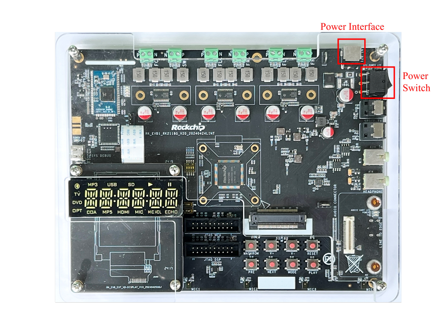
Figure 2-1 RK_EVB1_RK2118G_V20 development board
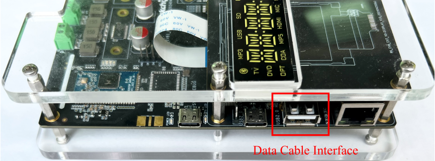
Figure 2-2 RK_EVB1_RK2118G_V20 development board
2. Data cable for connecting development board and computer
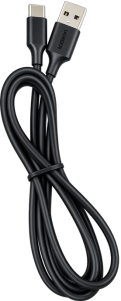
Figure2-3 USB-C USB data cable
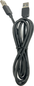
Figure 2-4 USB-A USB data cable
3. Power adapter
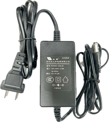
Figure 2-5 Power adapter with 12V-2A output
2.3 Connect the Development Board to the Computer
This section illustrates the connection process using the RK2118 development board as an example.
-
Prepare a computer with Ubuntu 18.04, Ubuntu 20.04, or Ubuntu 22.04 operating system.
-
Please note that the type and location of the data cable interface on the development board may vary between production batches. Refer to the provided schematic or documentation to locate the power interface and connect the development board’s power adapter.
-
Activate the power switch and wait for the development board’s system to boot up.
-
Use a USB Type-C cable to connect the ‘SYSTEM DEBUG’ port of the development board to the computer.
-
Utilize a serial communication tool on the computer to monitor the status of the RK2118. For example, you can use the ‘minicom’ application to establish a serial connection. The serial port baud rate should be set to 1500000 8N1.