
Based on the Chinese and English RK3576 Hardware Design Guide V1.1 (2024-05-28), for SoC-board design. CM5 carriers must follow the module interface; Sige5 can establish a software/peripheral baseline. This guide does not prescribe one SDK/BSP or kernel for every product; verify each board. Values are source references, not ArmSoM measurements.
RK3576_Hardware_Design_Guide_V1.1_20240528_EN.pdf · §2.3.5; SATA PCB
A SATA controller is not a complete drive connection
Two SATA 3.1 controllers support 1.5/3/6Gbps. The guide lists port-multiplier support for up to five devices, subject to software, device and bandwidth validation. SATA0 shares PHY0 with PCIe0; SATA1 shares PHY1 with PCIe1/USB3 OTG1. Drive power, spin-up current and connectors are separate from SATA signalling.
Do not copy PCIe RX wiring
The SATA reference uses 10nF coupling on both TX and RX, preferably 0201. eSATA protection capacitance is at most 0.4pF. CPDET/MPSWIT/CPPOD are selectable shared controls, not two independent sets for both ports. Check ACTLED IO voltage and external drive circuitry.
Include cables and worst-case supply conditions
Prefer 100Ω differential routing. Where stackup prevents this, the guide gives a conditional floor of 90Ω±10%; evaluate the whole cable/receiver path. Preserve ground, limit vias and place protection near connectors. Test cold boot, concurrent drives, sustained writes and recovery while measuring spin-up supply droop.
Design parameters and review table
| Item | Source reference |
|---|---|
| Rate | 1.5 / 3 / 6Gbps |
| TX + RX AC | 10nF |
| Intra-pair mismatch | <6mil |
| Trace length | <6inch |
| Airgap | ≥4W |
| Recommended via count | ≤2 |
Source figures
The reference pages below contain the relevant circuit or timing figures; click for full resolution. Designators and component values belong to the reference design, not an ArmSoM product schematic.
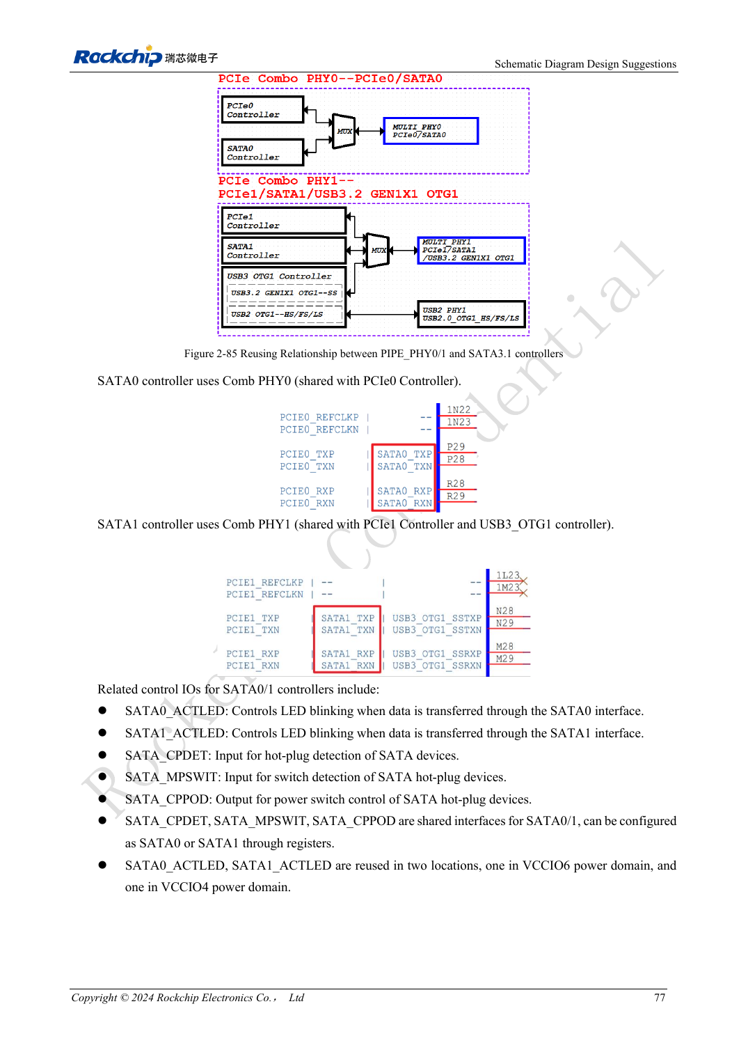
English original · PDF 96 · 2-85
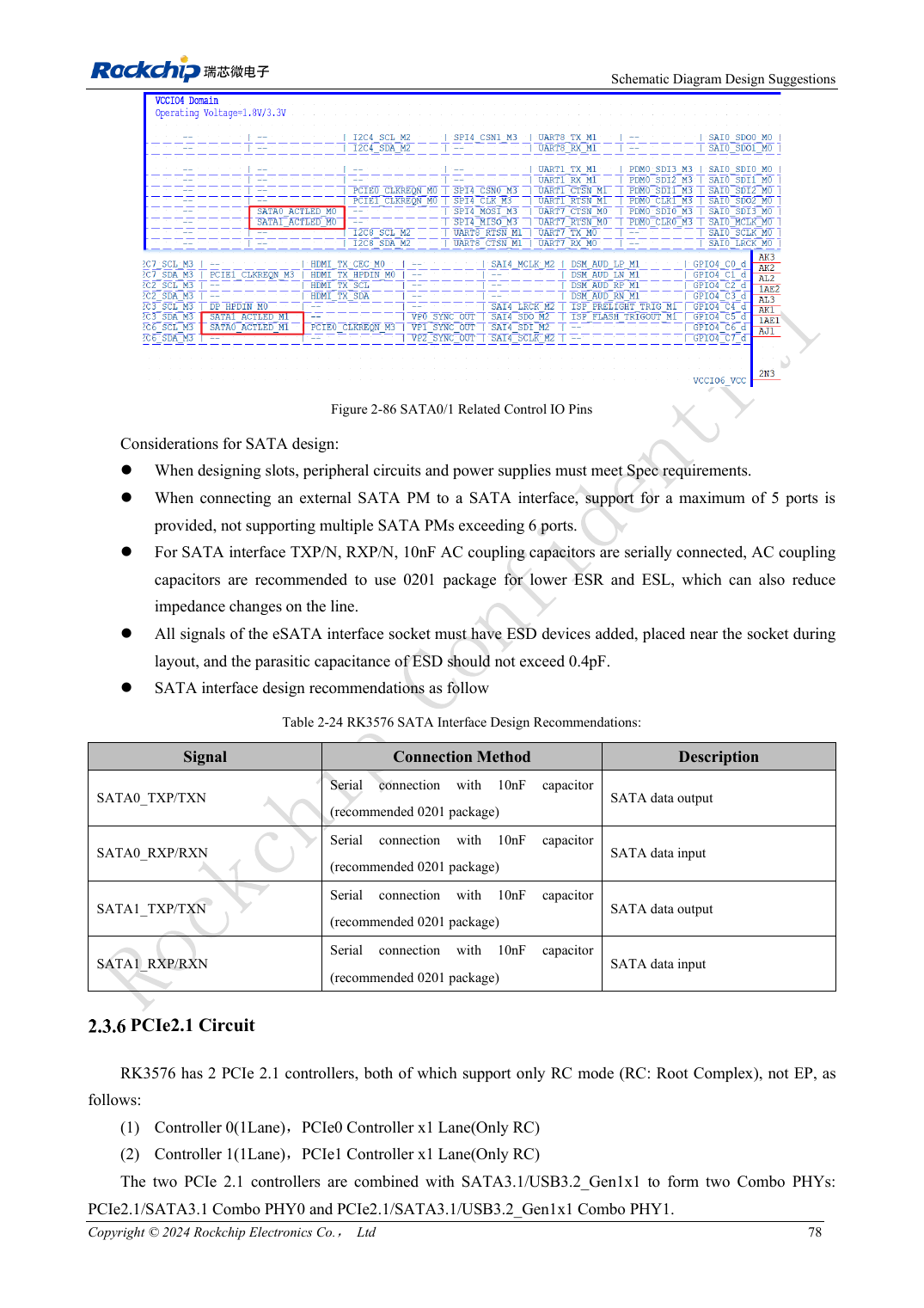
English original · PDF 97 · 2-86
ArmSoM development path
CM5 reduces repeated compute-core design on custom carriers; Sige5 provides a starting point for software and peripheral evaluation. Verify exposed interfaces, connector pins, voltages and image support in board documentation rather than inferring them from SoC features.