
Based on the Chinese and English RK3576 Hardware Design Guide V1.1 (2024-05-28), for SoC-board design. CM5 carriers must follow the module interface; Sige5 can establish a software/peripheral baseline. This guide does not prescribe one SDK/BSP or kernel for every product; verify each board. Values are source references, not ArmSoM measurements.
RK3576_Hardware_Design_Guide_V1.1_20240528_EN.pdf · Chapters 5–6
Protection needs a real discharge path
Place ESD devices at connector entry so signals pass protection before reaching the chip. Keep ground discharge short and away from sensitive circuitry. High-speed protection must satisfy capacitance as well as voltage requirements. Generic ESD resistor ranges do not replace interface-specific HDMI, USB or SDIO values.
Review reset, clocks and enclosure together
The guide recommends at least 5mm from board edges for reset, clock and interrupt nets. Place NPOR 100nF near the chip with a nearby ground via. Keep clock damping near the source and prefer inner routing with continuous return. Heatsinks and enclosures can radiate too; validate grounding at system level rather than repeatedly adding common-mode chokes.
Turn guidance into traceable tests
Record port, polarity, test point, mode and failure symptoms. After ESD check reset, communication, storage and recovery; lack of a crash does not prove data integrity. Before production review soldering, moisture and packaging. Source MSL3 floor life is 168 hours at ≤30°C/60%RH, not a storage promise for arbitrary packaging. Choose test levels from the target product standard; no certification is claimed.
Design parameters and review table
| Item | Source reference |
|---|---|
| Sensitive-net edge distance | ≥5mm |
| NPOR filter | 100nF |
| Clock damping distance | ≤400mil |
| MSL3 reference floor life | 168h; ≤30°C / 60%RH |
Source figures
The reference pages below contain the relevant circuit or timing figures; click for full resolution. Designators and component values belong to the reference design, not an ArmSoM product schematic.
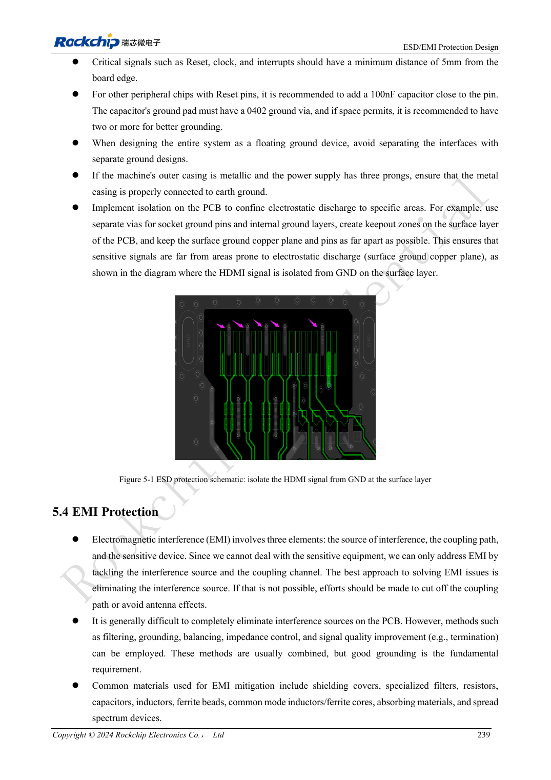
English original · PDF 258 · 5-1
ArmSoM development path
CM5 reduces repeated compute-core design on custom carriers; Sige5 provides a starting point for software and peripheral evaluation. Verify exposed interfaces, connector pins, voltages and image support in board documentation rather than inferring them from SoC features.