
This task-focused guide explains the source with key specifications, limitations and original figures. It is not a page-by-page translation or a complete pin/register manual. Vendor examples are not ArmSoM measurements. Check the actual board revision, schematic, SDK/BSP, kernel and drivers before applying them; no new hardware validation was performed for this article.
Primary source: Rockchip_RK3506G_EVB1_User_Guide_V1.0_20240719_CN.pdf · PDF 40 pages.
Separate the G reference from J products
The manual targets RK_EVB1_RK3506G_V10_20240511Pana.brd. Its table gives 128MB DDR3L and optional eMMC; the kit has a 12V/3A supply and a 1280×720 MIPI panel. CM1 and Forge1 are documented RK3506J products. Do not transfer the G EVB’s memory, temperature grade, supply or pins directly.
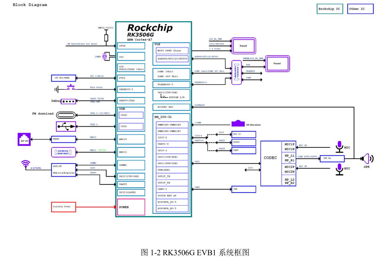
RK3506G EVB1 system diagram — Original Chinese figure; no corresponding English figure was found in this batch. Rockchip_RK3506G_EVB1_User_Guide_V1.0_20240719_CN.pdf, PDF p. 12.
Development paths on the reference board
| Path | Source implementation | Check before connecting |
|---|---|---|
| HMI | 2-lane MIPI DSI plus RGB expansion | Panel timing, backlight, touch and cable |
| Equipment network | 1 Fast Ethernet RJ45; second FEPHY via 60pin | Expansion PHY, power, multiplexing and driver |
| Control expansion | RGB/FLEXBUS/DSMC share 60pin | Resistor configuration and pinmux for the selected function |
| Field communication | CAN and RS485 | Transceiver, termination, wiring and ground reference |
| Audio | 1 speaker, 2 analogue MICs and onboard codec | Actual routes, clocks and mixer |
| USB | OTG0 Type-C for downloading; OTG1 Type-A | Role, supply and driver, not connector shape |
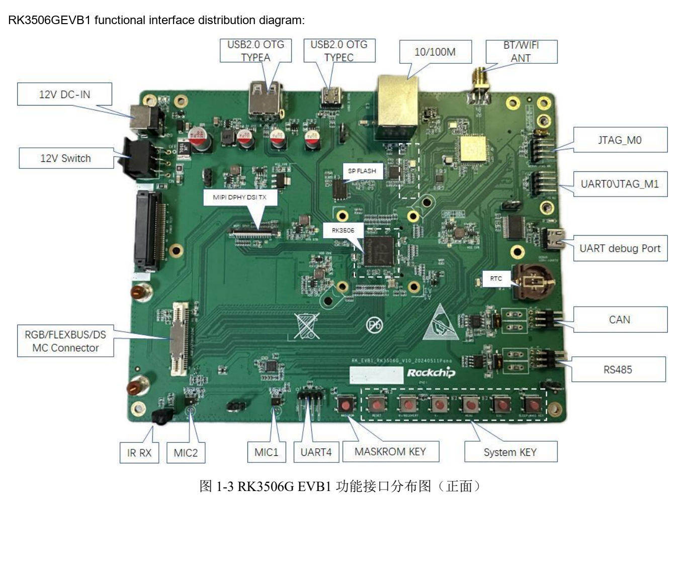
RK3506G EVB1 interface layout — Original Chinese figure; no corresponding English figure was found in this batch. Rockchip_RK3506G_EVB1_User_Guide_V1.0_20240719_CN.pdf, PDF p. 14.
Establish download and serial access first
The source uses download tool v3.28 or later. Enter the appropriate mode with MASKROM or V+(RECOVERY), confirm detection and select matching Loader, Parameter, Uboot and other files. Loader uses low SARADC_IN1. Follow the actual board’s supply/button instructions and back up before writing.
Debug Type-C is USB-UART at 1500000 (1.5M) baud, distinct from OTG0 downloading. Keep logs from power-on to userspace. Check supply, cables and ports before investigating kernel faults. An ADB-enabled image can additionally use:
adb devices
adb shell
Optional eMMC is a population choice
Page 27 gives this modification table only for the named reference board:
| Net | Source jumper direction |
|---|---|
| eMMC_CLKOUT | R1614→R1644 |
| eMMC_CMD | R1615→R1639 |
| eMMC_D0 | R1616→R1640 |
| eMMC_D1 | R1617→R1641 |
| eMMC_D2 | R1645→R1642 |
| eMMC_D3 | R1146→R1143 |
The final row’s numbering differs from the earlier rows; it is preserved, not silently changed to R16xx. Check schematic, BOM, assembly procedure and Loader/partition configuration before modification. This is not an instruction to modify CM1 or Forge1 at those positions.
I2C, termination and JTAG have conditions
I2C0 hosts HYM8563TS at 0x51 and ES8388 at 0x11, both 3.3V. Touch uses I2C2 at 0x28/0x29, 3.3V. This EVB’s audio section therefore cannot automatically serve as RK730 wiring documentation.
RS485 provides a 120Ω termination switch. Enable it according to the complete bus topology, not unconditionally at every node. Check CAN/RS485 wiring and supplies against the circuit with power removed.
JTAG_M0 shares Wi-Fi SDIO resources; the manual requires the corresponding switch configuration. The two JTAG headers swap TMS/TCK positions: M0 is GND, TMS, TCK, VCC; M1 is GND, TCK, TMS, VCC. Identical header shape is insufficient for connection.
Source issues and migration to products
The Wi-Fi table prints 1T21 while the overview says 1T1R. The last page retains an RK3576 header and labels a UART figure JTAG. These are recorded inconsistencies, not additional hardware capabilities.
Forge1 can be evaluated for HMI, gateways and interfaces; CM1 for a custom carrier. Rebuild the checklist for memory, boot medium, input supply, display, buses and software versions. Complete individual-interface and recovery tests before combining UI, networking, storage and field-bus load, then assess temperature and long-term stability.
Products and development resources
- CM1 — Product · Documentation
- Forge1 — Product · Documentation