
Complete technical content of Chinese V1.1.0. No English PDF exists; EN/RU/DE are full translations. All five figures come from the Chinese source and retain Chinese labels. Source scope: RV1109/RV1126 and RK356X Linux4.19; RK3588, RK3576, RV1106/RV1103, RV1106B/RV1103B Linux5.10; RV1126B Linux6.1. ArmSoM platform reference only: adapt board, camera module, SDK/BSP, power/IOMUX and kernel APIs individually. No universal board support. Boot times and failure percentages are source claims, not ArmSoM measurements. No hardware commands executed.
Source issues: probe/remove/ioctl signatures differ between definitions and tables; each is retained. Duplicate SC200AI_LGAIN, denominato/Ctrol/intput spellings and incorrect cross-references are not guessed away. Vertical Flip is not a180° rotation. Section6.5 percentages90%/9%/1%, MIPI limits, eye/slew/termination values are not verified universal standards. Do not directly apply “50Ω to ground”; hardware engineers must assess actual PHY, reference design and specifications to avoid damage. Stay within ratings, power off before reconnecting, restore temporary power_off changes. Internal test patterns alone do not validate optical dead pixels.
2. Preparation for debugging
Prepare the following materials before debugging the Camera driver:
2.1 Verify host specifications
Verify the host platform’s maximum supported resolution, upper input-frequency limit, maximum per-lane rate, supported lane count and input-interface type for this sensor.
2.2 Sensor DataSheet
Obtain the sensor manufacturer’s datasheet to check supply voltages and power-on/off sequencing; Chip ID for the probe check; exposure-time and gain settings and frame-rate changes; Slave-mode support, multicamera wiring and register configuration; test-mode and HDR support; and Mirror/Flip configuration.
2.3 Sensor Initialize Settings
Obtain the sensor register configuration list, normally from its manufacturer. Specify resolution, frame rate, lane count, per-lane rate, VTS, HTS, bit width and master clock. Prepare at least standard-resolution sequences; add special binning/crop sequences as the project requires. SmartSens example: cleaned_0x2b_SC530AI_27Minput_1080Mbps_2lane_10bit_1920x1080_60fps.ini. Its filename identifies sensor SC530AI, host-provided MCLK 27Mhz, sensor-to-host MIPI rate 1080Mbps per lane, 2 lanes, 10bit, 1920x1080 (1080p), and frame rate 60pfs (source spelling).
The following template requests configuration from the sensor manufacturer; select entries appropriate to the project.
sensor: XXXX
mclk: 24MHz/27Mhz/37.5Mhz
mode: raw8/raw10/raw12/raw16
output: 720p/1080p/1440p/... (resolution)
interface: mipi 1/2/4 Lane
frame rate: 30/60/120 fps
host: RK3588/RV1106/RV1103B/RV1126B/...
product: doorbell/doorbell/IPC/... (optional; source duplicates doorbell)
3. Driver development
3.1 Writing driver code
Base a new sensor driver on a similarly specified sensor in kernel/drivers/media/i2c/ or a nearby model from the same manufacturer. The following chapters use SmartSens SC200AI to explain the RK-platform development process.
3.1.1 Important sensor parameters
The sensor mode structure defines important parameters. Fill them accurately for every resolution.
struct XXXX_mode {
    u32 bus_fmt;    //输出像素格式
    u32 width;      //输出宽度
    u32 height;     //输出⾼度
    struct v4l2_fract max_fps; //最⼤输出帧率
    u32 hts_def;    //默认⾏总周期
    u32 vts_def;    //默认帧总周期
    u32 exp_def;    //默认曝光值
    u32 mipi_freq_idx;//链接频率索引值
    u32 bpp;        //每像素所⽤bit数
    const struct regval *reg_list; //寄存器列表
    u32 hdr_mode;   //宽动态模式
    u32 vc[PAD_MAX];//虚拟通道数组
};
The supported_modes array stores the mode structures for supported resolutions, traversed and matched during probe initialization or resolution changes. SC200AI example:
static const struct sc200ai_mode supported_modes[] = {
    { // 1080p 30fps 线性配置参数
    .width = 1920,
    .height = 1080,
    .max_fps = {
        .numerator = 10000,
        .denominator = 300000,
    },
    .exp_def = 0x0080,
    .hts_def = 0x44C * 2,
    .vts_def = 0x0465,
    .bus_fmt = MEDIA_BUS_FMT_SBGGR10_1X10,
    .reg_list = sc200ai_linear_10_1920x1080_30fps_regs,
    .hdr_mode = NO_HDR,
    .bpp = 10,
    .mipi_freq_idx = 1,
    .vc[PAD0] = V4L2_MBUS_CSI2_CHANNEL_0,
},
{ // 540p 120fps 线性配置参数
    .width = 960,
    .height = 540,
    .max_fps = {
        .numerator = 10000,
        .denominator = 1200000,
    },
    .exp_def = 0x0080,
    .hts_def = 0x420,
    .vts_def = 0x249,
    .bus_fmt = MEDIA_BUS_FMT_SBGGR10_1X10,
    .reg_list = sc200ai_linear_10_960x540_120fps_regs,
    .hdr_mode = NO_HDR,
    .bpp = 10,
    .mipi_freq_idx = 0,
    .vc[PAD0] = V4L2_MBUS_CSI2_CHANNEL_0,
},
{ // 1080p 30fps 宽动态配置参数
    .width = 1920,
    .height = 1080,
    .max_fps = {
        .numerator = 10000,
        .denominator = 300000,
    },
    .exp_def = 0x0080,
    .hts_def = 0x44C * 2,
    .vts_def = 0x08CC,
    .bus_fmt = MEDIA_BUS_FMT_SBGGR10_1X10,
    .reg_list = sc200ai_hdr_10_1920x1080_regs,
    .hdr_mode = HDR_X2,
    .bpp = 10,
    .mipi_freq_idx = 1,
    .vc[PAD0] = V4L2_MBUS_CSI2_CHANNEL_1,
    .vc[PAD1] = V4L2_MBUS_CSI2_CHANNEL_0,//L->csi wr0
    .vc[PAD2] = V4L2_MBUS_CSI2_CHANNEL_1,
    .vc[PAD3] = V4L2_MBUS_CSI2_CHANNEL_1,//M->csi wr2
},
}
Parameters:
bus_fmt is the sensor output pixel arrangement. The vendor sequence usually specifies bit width (e.g. 10bit); BGGR denotes Bayer order. Incorrect Bayer order still produces an image, but with a color cast.
width and height are the effective output dimensions and the most important parameters, generally smaller than hts and vts.
max_fps is the mode’s maximum frame rate, denominato / numerator (source spelling); numerator is generally unchanged. For exactly 30 frames/s, denominator is 300000.
exp_def is default exposure; hts_def is total points per line; vts_def is total lines per frame. Set all from initialization registers. Incorrect vts_def affects frame rate.
global_reg_list contains common initialization registers and may be empty; reg_list is the vendor register sequence. hdr_mode selects NO_HDR for linear operation or HDR_X2/HDR_X3 for two-/three-frame HDR fusion.
link_freq_idx indexes link_freq_menu_items. Manufacturers normally give Mbps per lane; MIPI samples both clock edges, so clock frequency is half the transfer rate. The first linear sequence is 720Mbps, thus MIPI/link_freq is 360M. An incorrect value easily prevents capture; check it repeatedly. bpp is bits per pixel.
Linear and HDR differ in hdr_mode and virtual-channel array vc. Linear: hdr_mode = NO_HDR, vc[PAD0] = V4L2_MBUS_CSI2_CHANNEL_0. HDR: hdr_mode = HDR_X2/HDR_X3; vc[PAD0] = V4L2_MBUS_CSI2_CHANNEL_0; vc[PAD1] = V4L2_MBUS_CSI2_CHANNEL_0; vc[PAD2] = V4L2_MBUS_CSI2_CHANNEL_1; vc[PAD3] = V4L2_MBUS_CSI2_CHANNEL_1.
3.1.2 Important sensor registers
The following important registers may be used in sensor driver development; details vary with manufacturer and model.
3.1.2.1 Chip id
Chip ID identifies each sensor during driver loading. The probe interface checks it; the source treats a correct ID as evidence of normal recognition, I2C read/write communication and supply voltages.
#define CHIP_ID                 0xcb1c
#define SC200AI_REG_CHIP_ID     0x3107
Some sensors have no Chip ID. To verify recognition and attachment, read one or more read-only registers and check their default values.
3.1.2.2 Ctrol mode
The stream-start/stop control register is normally written after all other sensor registers have been successfully programmed.
#define SC200AI_REG_CTRL_MODE       0x0100
#define SC200AI_MODE_SW_STANDBY     0x0
#define SC200AI_MODE_STREAMING      BIT(0)
Do not configure this register in the register sequence. Start/stop interface calls control its writes separately.
3.1.2.3 Exposure reg
Exposure-control registers may differ between linear and HDR modes; consult the sensor manual.
#define SC200AI_REG_EXPOSURE_H      0x3e00  //⻓曝光最⾼位
#define SC200AI_REG_EXPOSURE_M      0x3e01  //⻓曝光中间位
#define SC200AI_REG_EXPOSURE_L      0x3e02  //⻓曝光最低位
#define SC200AI_REG_SEXPOSURE_H     0x3e22  //短曝光最⾼位
#define SC200AI_REG_SEXPOSURE_M     0x3e04  //短曝光中间位
#define SC200AI_REG_SEXPOSURE_L     0x3e05  //短曝光最低位
#define SC200AI_EXPOSURE_MIN        1       //最新曝光⾏,⼀般不改,除⾮sensor有最⼩曝光限制
#define SC200AI_EXPOSURE_STEP       1       //曝光步进,⼀般不⽤修改
Exposure registers can exceed 16bit: e.g. a 24bit value has high, middle and low bytes and requires multiple writes. Long-/short-frame exposure may require separate writes. Gains may require specific formulas: analog gain may be linear or table-based; digital gain may be a floating-point factor represented in fixed point, such as Q8.8.
3.1.2.4 Gain reg
Gain registers control analog and digital gain. Each may have coarse gain (usually the integer part) and fine gain (usually the fractional part).
Analog gain amplifies sensor voltage in the analog domain before the ADC. It affects noise less than digital gain, but its range is limited and excessive gain increases noise and nonlinear distortion. Registers: ANA_GAIN (coarse), ANA_FINE_GAIN (fine).
Digital gain multiplies raw digital values, e.g. 10bit/12bit, after the ADC. It is simple and flexible but amplifies noise and quantization error, particularly colored noise in low light. Registers: DIG_GAIN (coarse), DIG_FINE_GAIN (fine).
Gain adjustment increases low-light brightness; AE dynamically adjusts gain and exposure time (shutter/line count) to reach target brightness; it controls image SNR and dynamic range.
#define SC200AI_REG_DIG_GAIN        0x3e06  //数字主增益
#define SC200AI_REG_DIG_FINE_GAIN   0x3e07  //数组精增益
#define SC200AI_REG_ANA_GAIN        0x3e08  //模拟主增益
#define SC200AI_REG_ANA_FINE_GAIN   0x3e09  //模拟精增益
#define SC200AI_REG_SDIG_GAIN       0x3e10  //短帧的数字主增益
#define SC200AI_REG_SDIG_FINE_GAIN  0x3e11  //短帧的数组精增益
#define SC200AI_REG_SANA_GAIN       0x3e12  //短帧的模拟主增益
#define SC200AI_REG_SANA_FINE_GAIN  0x3e13  //短帧的模拟精增益
#define SC200AI_GAIN_MIN            0x0040  //增益最⼩值
#define SC200AI_GAIN_MAX            (54 * 32 * 64)       //53.975*31.75*64 增益最⼤值
#define SC200AI_GAIN_STEP           1   //增益步进
#define SC200AI_GAIN_DEFAULT        0x0800  //默认增益值
#define SC200AI_LGAIN               0   //⻓帧增益
#define SC200AI_SGAIN               1   //短帧增益
In HDR, separate long-/short-frame gains may be required. The source names both distinctions SC200AI_LGAIN and SC200AI_LGAIN; this duplicated identifier is retained pending verification.
3.1.2.5 Group hold
Group Hold synchronizes exposure (shutter), gain and other CMOS-sensor updates. During capture of one frame, related parameters such as analog/digital gain and line exposure time must remain consistent to avoid stripes, uneven brightness or partly over-/underexposed images. These parameters are written through registers, whose changes normally take effect at the next frame/line boundary rather than immediately. Updating during capture can leave part of the image using old values and another part new values, creating a visible boundary or anomaly. Group Hold freezes update timing so all changes take effect together at a specified instant.
#define SC200AI_REG_GROUP_HOLD      0x3812 //group hold 控制寄存器
#define SC200AI_GROUP_HOLD_START    0x00  //开启Group Hold(冻结参数更新)即:Group Hold Start
#define SC200AI_GROUP_HOLD_END      0x30  //关闭Group Hold(释放参数更新)即:Group Hold End
3.1.2.6 Test pattern
A test-pattern register selects a CMOS/CCD mode that outputs internally generated patterns instead of real optical images. This synthetic image supports testing, debugging and verification. Typical patterns are color bars, gradients, checkerboards, solid red/green/blue/black/white, grids and Fixed Pattern Noise (FPN).
3.1.2.6.1 Test-pattern applications
- Sensor verification/debugging. Test patterns quickly check sensor image-data output, MIPI CSI-2 operation/data path, resolution and RAW/RGB/YUV format, and correct reception/processing by the ISP or downstream modules. For example, after first power-on the sensor can be checked without a real lens or light source.
If color bars or gradients appear on the display/debugging tool after enabling the pattern, the sensor and data path are basically working.
-
ISP debugging and algorithm validation. Test patterns verify Demosaic, 3A, Gamma, CSC, Sharpening and other blocks; compare processing under different inputs; and check color reproduction, brightness, contrast and noise suppression. Known, controllable inputs suit quantitative analysis and tuning. A solid red input should remain red, exposing white-balance/color-correction problems; gradients test Gamma, dynamic range and tone mapping.
-
Camera-module debugging/calibration. During production/calibration, patterns verify the lens-module + sensor + ISP data path, simulate AF/AE/AWB tests and provide basic functional checks without real illumination.
-
Fault isolation. For color casts, corruption, stripes or all-black/all-white output, enable the pattern. A normal pattern suggests optics (dirty lens/no light) or real-scene input; an abnormal pattern suggests sensor, MIPI, ISP or power. Thus it separates optical-link problems from electrical/data-processing problems.
-
Factory testing. The source lists automated sensor-output checks, dead/hot-pixel and fixed-noise checks, and validation of data integrity, color accuracy and dynamic range.
3.1.2.6.2 Common test-pattern types
| Test pattern | Description | Use |
|---|---|---|
| Solid Color | Entire image one color: red/green/blue/black/white | Color channels, defective pixels |
| Color Bars | TV-style color bars: red/green/blue/black/white combinations | Color output, ISP processing |
| Gradient | Smooth black-to-white or RGB transition | Dynamic range, Gamma, tone mapping |
| Checkerboard | Alternating black/white squares | Sharpness, edge processing, compression |
| Moving Pattern | Changing patterns supported by some sensors | Timing, buffers, latency |
| Random / Noise Pattern | Simulated noise | Noise-suppression algorithms |
| Cross Hatch / Grid | Crossed-line grid | Geometric distortion, alignment |
#define SC200AI_REG_TEST_PATTERN        0x4501 //测试图案控制寄存器
#define SC200AI_TEST_PATTERN_BIT_MASK   BIT(3) //测试图案开启掩码
3.1.2.7 VTS
HTS and VTS are key timing parameters in CMOS image sensors (CIS) and camera modules. VTS means Vertical Total Time or Vertical Total Lines: the total lines/time for a complete frame, including active and blanking lines. Usually expressed in lines, it can be converted to time (e.g. ms) according to frame rate and VTS. It includes:
-
Active Lines: actual image-data lines, e.g. 1080 for 1920x1080.
-
VSYNC (vertical synchronization)
-
Vertical blanking/front porch/back porch for frame switching and internal processing. VTS = active lines + vertical blanking lines. Relationship of HTS/VTS to resolution and frame rate:
-
Frame-rate calculation (FPS). Key formula:
FPS = PCLK / (HTS × VTS)
PCLK is Pixel Clock, normally in MHz or Hz, representing pixel-clock cycles transmitted per second.
HTS is total clock cycles per line (line duration); VTS is total lines per frame. Together they determine frame rate. Increase FPS by reducing VTS/vertical blanking or increasing PCLK. To reduce FPS, e.g. for longer low-light exposure, increase VTS or reduce PCLK. Key HTS/VTS differences:
| Item | HTS (Horizontal Total) | VTS (Vertical Total) |
|---|---|---|
| Direction | Horizontal, within one line | Vertical, within one frame |
| Meaning | Total clocks per line, active pixels + blanking | Total lines per frame, active + blanking |
| Includes | Active pixels + HSYNC + horizontal blanking | Active lines + VSYNC + vertical blanking |
| Affects | Line frequency, data-transfer timing | Frame rate, frame time |
| Frame rate | FPS = PCLK / (HTS × VTS) | Increasing VTS lowers FPS; decreasing raises it |
| Unit | Clock cycles/pixel clocks | Lines |
| Typical configuration | Sensor line-timing registers | Sensor frame-timing registers |
#define SC200AI_REG_VTS_H       0x320e
#define SC200AI_REG_VTS_L       0x320f
3.1.2.8 Mirror / Flip
Mirror/Flip registers control sensor-output orientation: left/right or up/down geometric transformations.
-
Mirror horizontally reverses left and right along X, like a mirror. Set the Mirror/Horizontal Flip bit when horizontal installation or lens orientation reverses the image.
-
Flip vertically exchanges top and bottom along Y. The source compares this with rotating a photo 180° or looking down from a ceiling; that analogy is retained but a vertical reflection alone is not a 180° rotation. Sensor function:
Set the Flip/Vertical Flip bit for vertical reflection, typically for an upside-down sensor or to match display orientation. Combined Mirror/Flip effects:
| Setting | Effect | Appearance |
|---|---|---|
| No Mirror / no Flip | Normal | Unflipped, normal viewing direction (default) |
| Mirror | Left/right reversal | Like a mirror |
| Flip | Top/bottom reversal | Upside-down photo |
| Mirror + Flip | Horizontal + vertical reflection = 180° rotation | All directions reversed; looks rotated 180° |
Most CMOS sensors, including Sony, OmniVision, SmartSens, GalaxyCore and Onsemi, configure Mirror/Flip through registers.
#define SC200AI_FLIP_MIRROR_REG     0x3221 // 镜像翻转控制寄存器

#define SC200AI_FETCH_MIRROR(VAL, ENABLE)   (ENABLE ? VAL | 0x06 : VAL & 0xf9)//设置镜像
#define SC200AI_FETCH_FLIP(VAL, ENABLE)     (ENABLE ? VAL | 0x60 : VAL & 0x9f)//设置翻转
- Set mirror/flip with v4l2-ctl
// /dev/v4l-subdev2节点对应 Sensor ⼦设备节点。参考5.4 章节
v4l2-ctl --set-ctrl=horizontal_flip=1 -d /dev/v4l-subdev2  # 启⽤⽔平镜像
v4l2-ctl --set-ctrl=horizontal_flip=0 -d /dev/v4l-subdev2  # 禁⽤⽔平镜像

v4l2-ctl --set-ctrl=vertical_flip=1 -d /dev/v4l-subdev2    # 启⽤垂直翻转
v4l2-ctl --set-ctrl=vertical_flip=0  -d /dev/v4l-subdev2   # 禁⽤垂直翻转

v4l2-ctl --set-ctrl=horizontal_flip=1 --set-ctrl=vertical_flip=1 -d /dev/v4l-subdev2
 # 同时启⽤镜像和翻转
v4l2-ctl --set-ctrl=horizontal_flip=0 --set-ctrl=vertical_flip=0  -d /dev/v4l-subdev2#
同时禁⽤镜像和翻转
3.2 Driver framework
The camera sensor communicates with the host over I2C. Its driver is implemented as an I2C device driver and uses V4L2 subdev to interact with the host driver.
3.2.1 Data types
3.2.1.1 struct i2c_driver
Description: I2C device-driver information. Definition:
struct i2c_driver {
    ...

    /* Standard driver model interfaces */
    int (*probe)(struct i2c_client *client, const struct i2c_device_id *id);
    int (*remove)(struct i2c_client *client);
    ...
    struct device_driver driver;
    const struct i2c_device_id *id_table;
    ...
};
Key members:
| Member | Data type | Description |
|---|---|---|
| probe | int (*)(struct i2c_client *) | Device-probing function, called when the driver matches a device |
| remove | void (*)(struct i2c_client *) | Device-removal cleanup function |
| driver | struct device_driver | Core driver structure; .probe is called when compatible in of_match_table matches compatible in the DTS file |
| id_table | const struct i2c_device_id * | Device matching table; if the kernel does not match using of_match_table and DTS-registered devices, it uses this table |
Example:
#if IS_ENABLED(CONFIG_OF)
static const struct of_device_id sc200ai_of_match[] = {
    { .compatible = "smartsens,sc200ai" },
    {},
};
MODULE_DEVICE_TABLE(of, sc200ai_of_match);
#endif

static const struct i2c_device_id sc200ai_match_id[] = {
    { "smartsens,sc200ai", 0 },
    { },
};

static struct i2c_driver sc200ai_i2c_driver = {
    .driver = {
        .name = SC200AI_NAME,
        .pm = &sc200ai_pm_ops,
        .of_match_table = of_match_ptr(sc200ai_of_match),
    },
    .probe      = &sc200ai_probe,
    .remove     = &sc200ai_remove,
    .id_table   = sc200ai_match_id,
};

static int __init sensor_mod_init(void)
{
    return i2c_add_driver(&sc200ai_i2c_driver);
}

static void __exit sensor_mod_exit(void)
{
    i2c_del_driver(&sc200ai_i2c_driver);
}
3.2.1.2 struct v4l2_subdev_ops
Description: struct v4l2_subdev_ops is the core V4L2 subdevice-operation structure, defining interfaces for hardware such as sensors, ISPs and decoders. Definition:
struct v4l2_subdev_ops {
    const struct v4l2_subdev_core_ops   *core;
    const struct v4l2_subdev_video_ops  *video;
    const struct v4l2_subdev_pad_ops    *pad;
    ...
};
Key members:
| Member type | Structure | Function | Applicable hardware |
|---|---|---|---|
| Core operations | const struct v4l2_subdev_core_ops *core | Basic control (power/interrupts/logging, etc.) | All subdevices |
| Video-stream control | const struct v4l2_subdev_video_ops *video | Video-stream parameters (frame rate/format/HDR, etc.) | Sensor/ISP/encoder |
| Pad control | const struct v4l2_subdev_pad_ops *pad | Pixel format/resolution/crop settings (critical) | Sensor/ISP/MIPI-CSI receiver |
Example:
static const struct v4l2_subdev_ops sc200ai_subdev_ops = {
    .core   = &sc200ai_core_ops,
    .video  = &sc200ai_video_ops,
    .pad    = &sc200ai_pad_ops,
};
3.2.1.3 struct v4l2_subdev_core_ops
Description: operations implementing core control functions in a V4L2 subdevice driver. Definition:
struct v4l2_subdev_core_ops {
    ...
    long (*ioctl)(struct v4l2_subdev *sd, unsigned int cmd, void *arg);
#ifdef CONFIG_COMPAT
    long (*compat_ioctl32)(struct v4l2_subdev *sd, unsigned int cmd,
                   unsigned long arg);
#endif
    int (*s_power)(struct v4l2_subdev *sd, int on);
    ...
};
Key members:
| Member function | Prototype | Function | Typical RK Sensor implementation |
|---|---|---|---|
| s_power | int (*)(struct v4l2_subdev *sd, int on) | Control power state: turn device power on/off | Control PWDN/RESET pin-level sequences and PMIC power timing (on=1 powers up; on=0 powers down) |
| compat_ioctl32 | long (*compat_ioctl32)(struct v4l2_subdev *sd, unsigned int cmd, unsigned long arg) | Implement private functionality for 32-bit applications on a 64-bit kernel, handling data transferred from/to userspace | |
| ioctl | int (*)(struct v4l2_subdev *sd, unsigned int cmd, void *arg) | Handle private custom commands (non-standard V4L2 commands) | Implement specific features and respond to system ioctl calls |
Example:
static const struct v4l2_subdev_core_ops sc200ai_core_ops = {
    .s_power = sc200ai_s_power,
    .ioctl = sc200ai_ioctl,
#ifdef CONFIG_COMPAT
    .compat_ioctl32 = sc200ai_compat_ioctl32,
#endif
};c
The following private ioctl commands query module information and query/configure OTP information.
| Private ioctl | Description |
|---|---|
| RKMODULE_GET_MODULE_INFO | Get module information |
| PREISP_CMD_SET_HDRAE_EXP | Set HDR exposure |
| RKMODULE_SET_HDR_CFG | Set HDR mode; switch normal/linear and HDR. Driver must support both configuration sets |
| RKMODULE_GET_HDR_CFG | Get current HDR mode |
| RKMODULE_SET_CONVERSION_GAIN | Set linear-mode conversion gain, supported e.g. by imx347/os04a10; optional if the sensor lacks it |
3.2.1.4 struct v4l2_subdev_video_ops
Description: video-device control interface. Definition:
struct v4l2_subdev_video_ops {
    ...
    int (*s_stream)(struct v4l2_subdev *sd, int enable);
    int (*g_frame_interval)(struct v4l2_subdev *sd,
                struct v4l2_subdev_frame_interval *interval);
    int (*s_frame_interval)(struct v4l2_subdev *sd,
                struct v4l2_subdev_frame_interval *interval);
    ...

};
Key members:
| Member | Description |
|---|---|
| .g_frame_interval | Callback for VIDIOC_SUBDEV_G_FRAME_INTERVAL ioctl |
| .s_stream | Key interface notifying driver to start/stop video streaming |
| .s_frame_interval | Dynamically change sensor frame rate/interval; core adjustment callback |
Example:
static const struct v4l2_subdev_video_ops sc200ai_video_ops = {
    .s_stream = sc200ai_s_stream,
    .g_frame_interval = sc200ai_g_frame_interval,
    .s_frame_interval = sc200ai_s_frame_interval,
};
3.2.1.5 struct v4l2_subdev_pad_ops
Description: callbacks for subdevice pixel-format negotiation, cropping, scaling and frame layout. In RK sensor drivers this is the key interface configuring the sensor → ISP → memory pipeline. Definition:
struct v4l2_subdev_pad_ops {
    ...
    int (*enum_mbus_code)(struct v4l2_subdev *sd,
                  struct v4l2_subdev_pad_config *cfg,
                  struct v4l2_subdev_mbus_code_enum *code);
    int (*enum_frame_size)(struct v4l2_subdev *sd,
                   struct v4l2_subdev_pad_config *cfg,
                   struct v4l2_subdev_frame_size_enum *fse);
    int (*enum_frame_interval)(struct v4l2_subdev *sd,
                   struct v4l2_subdev_pad_config *cfg,
                   struct v4l2_subdev_frame_interval_enum *fie);
    int (*get_fmt)(struct v4l2_subdev *sd,
               struct v4l2_subdev_pad_config *cfg,
               struct v4l2_subdev_format *format);
    int (*set_fmt)(struct v4l2_subdev *sd,
               struct v4l2_subdev_pad_config *cfg,
               struct v4l2_subdev_format *format);
    int (*get_selection)(struct v4l2_subdev *sd,
                 struct v4l2_subdev_pad_config *cfg,
                 struct v4l2_subdev_selection *sel);
    int (*set_selection)(struct v4l2_subdev *sd,
                 struct v4l2_subdev_pad_config *cfg,
                 struct v4l2_subdev_selection *sel);
    int (*get_edid)(struct v4l2_subdev *sd, struct v4l2_edid *edid);
    int (*set_edid)(struct v4l2_subdev *sd, struct v4l2_edid *edid);
    int (*dv_timings_cap)(struct v4l2_subdev *sd,
                  struct v4l2_dv_timings_cap *cap);
    int (*enum_dv_timings)(struct v4l2_subdev *sd,
                   struct v4l2_enum_dv_timings *timings);
    ...

    int (*get_mbus_config)(struct v4l2_subdev *sd, unsigned int pad,
                   struct v4l2_mbus_config *config);
    int (*set_mbus_config)(struct v4l2_subdev *sd, unsigned int pad,
                   struct v4l2_mbus_config *config);
};
Key members:
| Member | Description |
|---|---|
| enum_mbus_code | Enumerate media-bus pixel formats; report sensor RAW/YUV, e.g. MEDIA_BUS_FMT_SRGGB10_1X10. |
| get_fmt | Get current resolution/pixel format, e.g. 1920x1080@SRGGB10. |
| set_fmt | Set resolution/pixel format; most important function. Configure e.g. 1920x1080 and NV12; affects MIPI stream. |
| enum_frame_size | Enumerate resolutions for a pixel format, e.g. 640x480/1280x720 for UYVY. |
| enum_frame_interval | Enumerate frame rates for format/resolution; report current-mode resolutions/rates. |
| get_selection | Get crop/scale regions (read/write area, output size); digital zoom or small low-power region. |
| set_selection | Set crop/scale regions; use a1080p region in preview. |
| get_edid/set_edid | Handle Extended Display Identification Data; HDMI receivers, normally ignored by sensor drivers. |
| dv_timings_cap | Get supported digital-video timing standards; HDMITX/RX only. |
| enum_dv_timings | Enumerate digital-video timings; HDMITX/RX only. |
| get_mbus_config | Get media-bus configuration, e.g. MIPI D-PHY; report lane count V4L2_MBUS_CSI2_4LANE and clock mode V4L2_MBUS_CSI2_CONTINUOUS_CLOCK. |
| set_mbus_config | Set bus configuration; dynamically change MIPI, e.g.2-lane/4-lane. |
Example:
static const struct v4l2_subdev_pad_ops sc200ai_pad_ops = {
    .enum_mbus_code = sc200ai_enum_mbus_code,
    .enum_frame_size = sc200ai_enum_frame_sizes,
    .enum_frame_interval = sc200ai_enum_frame_interval,
    .get_fmt = sc200ai_get_fmt,
    .set_fmt = sc200ai_set_fmt,
    .get_mbus_config = sc200ai_g_mbus_config,
};
3.2.1.6 struct v4l2_ctrl_ops
Description: struct v4l2_ctrl_ops is the V4L2 control framework’s core operation set for dynamically controlling exposure, gain, white balance and other sensor parameters. On Rockchip it provides a standard interface for application configuration requests, linking userspace controls to hardware-register operations. Definition:
struct v4l2_ctrl_ops {
    ...
    int (*s_ctrl)(struct v4l2_ctrl *ctrl);
};
Key members:
| Member | Function | Typical Rockchip implementation |
|---|---|---|
| s_ctrl | Set control value (most important) | Write userspace values to hardware registers, e.g. exposure/gain |
Example:
static int sc200ai_set_ctrl(struct v4l2_ctrl *ctrl)
{
    struct sc200ai *sc200ai = container_of(ctrl->handler,
                           struct sc200ai, ctrl_handler);
    struct i2c_client *client = sc200ai->client;

    ...

    if (!pm_runtime_get_if_in_use(&client->dev))
        return 0;

    switch (ctrl->id) {
    case V4L2_CID_EXPOSURE:
        dev_dbg(&client->dev, "set exposure value 0x%x\n", ctrl->val);
        ...
        break;
    case V4L2_CID_ANALOGUE_GAIN:
        dev_dbg(&client->dev, "set gain value 0x%x\n", ctrl->val);
        ...
        break;
    case V4L2_CID_VBLANK:
        dev_dbg(&client->dev, "set blank value 0x%x\n", ctrl->val);
        ...
        break;
    case V4L2_CID_TEST_PATTERN:
        ...
        break;
    case V4L2_CID_HFLIP:
        ...
        break;
    case V4L2_CID_VFLIP:
        ...
        break;
    default:
        dev_warn(&client->dev, "%s Unhandled id:0x%x, val:0x%x\n",
             __func__, ctrl->id, ctrl->val);
        break;
    }

    pm_runtime_put(&client->dev);

    return ret;
}

static const struct v4l2_ctrl_ops sc200ai_ctrl_ops = {
    .s_ctrl = sc200ai_set_ctrl,
};
3.2.2 APIs
3.2.2.1 xxxx_set_fmt
Description: set sensor output format. A driver may support multiple resolutions; set_fmt passes the requested resolution and the driver finds the closest match. Linear/HDR switching does not use this function but a private ioctl command. Switching requires equal resolutions in linear and HDR modes. Syntax:
static int xxxx_set_fmt(struct v4l2_subdev *sd,
                        struct v4l2_subdev_pad_config *cfg,
                        struct v4l2_subdev_format *fmt)
Parameters:
| Parameter | Description | Direction |
|---|---|---|
| *sd | Pointer to v4l2 subdev structure | Input |
| *cfg | Pointer to subdev pad information structure | Input |
| *fmt | Pointer to Pad-level media bus format structure | Input |
Return values:
| Return value | Description |
|---|---|
| 0 | Success |
| Nonzero | Failure |
Note: kernel 6.1 replaces struct v4l2_subdev_pad_config *cfg with struct v4l2_subdev_state *sd_state.
3.2.2.2 xxxx_get_fmt
Description: get the current sensor output format. struct xxx_mode may contain several resolutions; initialization selects one, or set_fmt changes it. get_fmt confirms the current configuration. Before RK3588, fmt->reserved[0] also reports the device’s virtual channel, allowing this parameter to specify the channel instead of the default. RK3588 and later use ioctl RKMODULE_GET_CHANNEL_INFO to obtain channel information. Syntax:
static int xxxx_get_fmt(struct v4l2_subdev *sd,
                        struct v4l2_subdev_pad_config *cfg,
                        struct v4l2_subdev_format *fmt)
Parameters:
| Parameter | Description | Direction |
|---|---|---|
| *sd | Pointer to v4l2 subdev structure | Input |
| *cfg | Pointer to subdev pad information structure | Input |
| *fmt | Pointer to Pad-level media bus format structure | Output |
Return values:
| Return value | Description |
|---|---|
| 0 | Success |
| Nonzero | Failure |
Note: kernel 6.1 replaces struct v4l2_subdev_pad_config *cfg with struct v4l2_subdev_state *sd_state.
3.2.2.3 xxxx_enum_mbus_code
Description: enumerate sensor output bus formats. A static struct xxx_mode variable contains supported resolutions; return the enumerated bus format from its entries. Syntax:
static int xxxx_enum_m bus_code(struct v4l2_subdev *sd,
                                struct v4l2_subdev_pad_config *cfg,
                                struct v4l2_subdev_mbus_code_enum *code)
Parameters:
| Parameter | Description | Direction |
|---|---|---|
| *sd | Pointer to v4l2 subdev structure | Input |
| *cfg | Pointer to subdev pad information structure | Input |
| *code | Pointer to media bus format enumeration structure | Output c (source spelling) |
Return values:
| Parameter | Description | Direction |
|---|---|---|
| *sd | Pointer to v4l2 subdev structure | Input |
| *cfg | Pointer to subdev pad information structure | Input |
| *code | Pointer to media bus format enumeration structure | Output |
Note: kernel 6.1 replaces struct v4l2_subdev_pad_config *cfg with struct v4l2_subdev_state *sd_state.
3.2.2.4 xxxx_enum_frame_sizes
Description: enumerate sensor output sizes. A static struct xxx_mode variable contains supported resolutions; return enumerated sizes from its entries. Syntax:
static int xxxx_enum_frame_sizes(struct v4l2_subdev *sd,
                                struct v4l2_subdev_pad_config *cfg,
                                struct v4l2_subdev_frame_size_enum *fse)
Parameters:
| Parameter | Description | Direction |
|---|---|---|
| *sd | Pointer to v4l2 subdev structure | Input |
| *cfg | Pointer to subdev pad information structure | Input |
| *fse | Pointer to media bus frame size structure | Output |
Return values:
| Return value | Description |
|---|---|
| 0 | Success |
| Nonzero | Failure |
Note: kernel 6.1 replaces struct v4l2_subdev_pad_config *cfg with struct v4l2_subdev_state *sd_state.
3.2.2.5 xxxx_g_frame_interval
Description: get sensor output frame interval. The static struct xxx_mode configuration specifies maximum frame rate. The driver reduces frame rate by increasing vblank. To report actual frame rate, convert using default and current vblank, then return the updated interval to the application. Syntax:
static int xxxx_g_frame_interval(struct v4l2_subdev *sd,
                                struct v4l2_subdev_frame_interval *fi)
Parameters:
| Parameter | Description | Direction |
|---|---|---|
| *sd | Pointer to v4l2 subdev structure | Input |
| *fi | Pointer to pad-level frame rate structure | Output |
Return values:
| Return value | Description |
|---|---|
| 0 | Success |
| Nonzero | Failure |
3.2.2.6 xxxx_s_stream
Description: configure stream input/output. The on argument selects start_stream or stop_stream. start_stream programs the initialization register array, initializes exposure parameters and enables data streaming; stop_stream writes stream-off registers. Syntax:
static int xxxx_s_stream(struct v4l2_subdev *sd, int on)
Parameters:
| Parameter | Description | Direction |
|---|---|---|
| *sd | Pointer to v4l2 subdev structure | Input |
| on | 1: start stream output; 0: stop | Input |
Return values:
| Return value | Description |
|---|---|
| 0 | Success |
| Nonzero | Failure |
3.2.2.7 xxxx_runtime_resume
Description: sensor power-up callback. Placing power-up here allows other sensor-driver code or upper drivers to power it on with pm_runtime_get_sync. Syntax:
static int xxxx_runtime_resume(struct device *dev)
Parameters:
| Parameter | Description | Direction |
|---|---|---|
| *dev | Pointer to device structure | Input |
Return values:
| Return value | Description |
|---|---|
| 0 | Success |
| Nonzero | Failure |
3.2.2.8 xxxx_runtime_suspend
Description: sensor power-down callback. Other sensor-driver code or upper drivers invoke shutdown through pm_runtime_put. Syntax:
static int xxxx_runtime_suspend(struct device *dev)
Parameters:
| Parameter | Description | Direction |
|---|---|---|
| *dev | Pointer to device structure | Input |
Return values:
| Return value | Description |
|---|---|
| 0 | Success |
| Nonzero | Failure |
3.2.2.9 xxxx_set_ctrl
Description: set V4L2 control values. Register this callback for V4L2 control commands; application parameter changes then configure the sensor through it. Implement controls as described in section 3.2.1.6, struct v4l2_ctrl_ops. Syntax:
static int xxxx_set_ctrl(struct v4l2_ctrl *ctrl)
Parameters:
| Parameter | Description | Direction |
|---|---|---|
| *ctrl | Pointer to v4l2_ctrl structure | Input |
Return values:
| Return value | Description |
|---|---|
| 0 | Success |
| Nonzero | Failure |
3.2.2.10 xxx_enum_frame_interval
Description: enumerate supported sensor frame intervals from the resolutions in the static struct xxx_mode variable. This is generally of limited use; actual frame-rate adjustment still uses vblank. Syntax:
static int xxxx_enum_frame_interval(struct v4l2_subdev *sd,
                                    struct v4l2_subdev_pad_config *cfg,
                                    struct v4l2_subdev_frame_interval_enum *fie)
Parameters:
| Parameter | Description | Direction |
|---|---|---|
| *sd | Subdevice instance | Input |
| *cfg | Pad configuration | Input |
| *fie | Frame-interval parameters | Output |
Return values:
| Return value | Description |
|---|---|
| 0 | Success |
| Nonzero | Failure |
Note: kernel 6.1 replaces struct v4l2_subdev_pad_config *cfg with struct v4l2_subdev_state *sd_state.
3.2.2.11 xxxx_g_mbus_config
Description: get supported bus configuration. Bus types include parallel, MIPI and LVDS; parallel includes BT601/BT656/BT1120 and MIPI includes DPHY/CPHY. The controller reads the current sensor bus parameters to determine capture mode. For sensors with multiple MIPI modes, report parameters for the active mode. Syntax:
static int xxxx_g_m bus_config(struct v4l2_subdev *sd,
                                struct v4l2_m bus_config *config)
Parameters:
| Parameter | Description | Direction |
|---|---|---|
| *config | Bus configuration | Output c (source spelling) |
Return values:
| Parameter | Description | Direction |
|---|---|---|
| *config | Bus configuration | Output |
3.2.2.12 xxxx_get_selection
Description: configure cropping. ISP input width must align to 16 and height to 8. Implement this function to crop sensor outputs that are unaligned or use a nonstandard resolution before ISP input. Syntax:
static int xxxx_get_selection(struct v4l2_subdev *sd,
                             struct v4l2_subdev_pad_config *cfg,
                             struct v4l2_subdev_selection *sel)
Parameters:
| Parameter | Description | Direction |
|---|---|---|
| *sd | Subdevice instance | Input |
| *cfg | Pad configuration | Input |
| *sel | Crop parameters | Output |
Return values:
| Return value | Description |
|---|---|
| 0 | Success |
| Nonzero | Failure |
Note: kernel 6.1 replaces struct v4l2_subdev_pad_config *cfg with struct v4l2_subdev_state *sd_state.
3.2.2.13 xxxx_ioctl
Description: implement private ioctl commands. Syntax:
static long xxxx_ioctl(struct v4l2_subdev *sd, unsigned int cmd, void *arg)
Parameters:
| Parameter | Description | Direction |
|---|---|---|
| *sd | Subdevice instance | Input |
| cmd | Private command value (source: naming value) | Input |
| * arg | Passed parameters | Input/output |
Return values:
| Return value | Description |
|---|---|
| 0 | Success |
| Nonzero |
3.3 Driver porting procedure
3.3.1 Standard I2C subdevice driver
-
Implement these struct i2c_driver members: struct driver.name, struct driver.pm, struct driver.of_match_table, probe and remove. Note the return-value difference between kernel 5.10 and 6.1.
-
probe implementation: obtain CIS resources, mainly by parsing DTS. RK private resources use rockchip,camera-module-xxx names and are passed to userspace camera_engine to select matching IQ parameters. RK reference drivers normally define these CIS resources:
| Member | Description |
|---|---|
| CIS reference clock | No resource is needed for an independent crystal. RK reference designs generally use an AP output clock, normally named xvclk, which must be obtained. |
| CIS control GPIO | For example Resst (source spelling) and Powerdown pins. |
| CIS power resources | Acquire software power-control resources matching hardware, e.g. gpio or regulator. |
After acquiring resources, reading the CIS device ID is recommended to verify hardware, but is optional. Initialize the CIS V4L2 device and media entity. Use v4l2_i2c_subdev_init for the subdevice. RK requires a dedicated subdev device node for userspace rk_aiq exposure control. Initialize the media entity with media_entity_init.
3.3.2 V4L2 subdevice driver
Mainly implement these three members:
struct v4l2_subdev_core_ops
struct v4l2_subdev_video_ops
struct v4l2_subdev_pad_ops
- Implement callbacks described by struct v4l2_subdev_core_ops. s_power powers the sensor on/off. For long register arrays, separate common registers and program them after power-up; let s_stream set only resolution-specific registers to speed switching. Also implement .compat_ioctl32 and .ioctl; ioctl provides RK private controls including:
| Member | Description |
|---|---|
| RKMODULE_GET_MODULE_INFO | Pass DTS module information, e.g. module name, to camera_engine for matching. |
| RKMODULE_AWB_CFG | With module OTP enabled, camera_engine passes typical-module AWB calibration. The CIS driver compares current-module AWB calibration and computes R/B Gain for CIS MWB. |
| RKMODULE_LSC_CFG | With OTP enabled, camera_engine enables application of LSC calibration. |
| PREISP_CMD_SET_HDRAE_EXP | HDR exposure settings |
| RKMODULE_SET_HDR_CFG | Switch HDR/normal; driver supports both configuration sets. |
| RKMODULE_GET_HDR_CFG | Get current HDR mode |
| RKMODULE_SET_CONVERSION_GAIN | Set linear conversion gain, e.g. imx347/os04a10. High conversion gain improves low-light SNR. Optional without sensor support. |
| RKMODULE_SET_QUICK_STREAM | Set stream on/off registers for abnormal reset, synchronized multicamera start (see synchronization mechanism), fast boot and AOV. |
| RKMODULE_GET_CHANNEL_INFO | Get channel information. Default vicap id0–id3 map to vc0–vc3; customize for SPD/EBD acquisition. Before RK3588, get_fmt still retrieves channels. |
| RKMODULE_GET_SYNC_MODE, RKMODULE_SET_SYNC_MODE | Get/set synchronization mode; see multicamera synchronization. |
- Refer to struct v4l2_subdev_core_ops (source reference) and implement the following callbacks:
| Member | Description |
|---|---|
| .s_stream | Start/stop streaming. With continuous MIPI CLK, start inside this callback; earlier start prevents detecting MIPI LP state. |
| .g_frame_interval | Get frame interval/frame rate |
| .g_mbus_config | Get bus configuration. With multiple lane counts or HDR, report MIPI settings of the active sensor mode. |
- Refer to struct v4l2_subdev_pad_ops and implement these callbacks:
| Member | Description |
|---|---|
| .enum_mbus_code | Enumerate supported formats; see xxxx_enum_mbus_code. |
| .enum_frame_size | Enumerate resolutions; see xxxx_enum_frame_sizes. |
| .get_fmt | Required: RKISP reads CIS output format here. See MEDIA_BUS_FMT for Bayer raw, SoC YUV and BW raw; struct v4l2_mbus_framefmt for field output; implementation xxxx_get_fmt. |
| .set_fmt | Required: set CIS format/resolution; xxxx_set_fmt. |
| .enum_frame_interval | Enumerate frame intervals including resolution; xxx_enum_frame_interval. |
| .get_selection | Crop: ISP width aligned to16, height to8; xxxx_get_selection. |
- Refer to struct v4l2_ctrl_ops and implement these callbacks:
| Member | Description |
|---|---|
| .s_ctrl | RKISP driver and camera_engine use different commands to control CIS exposure. |
The following IDs provide information and are implemented as standard integer menu controls:
| Member | Description |
|---|---|
| V4L2_CID_LINK_FREQ | See standard definition in CIS V4L2-controls list; RKISP uses it to obtain MIPI bus frequency. |
| V4L2_CID_PIXEL_RATE | MIPI: pixel_rate = link_freq * 2 * nr_of_lanes / bits_per_sample |
| V4L2_CID_HBLANK | See CIS V4L2-controls standard definition. |
| V4L2_CID_VBLANK | See CIS V4L2-controls standard definition. |
RK camera_engine obtains the necessary exposure-calculation information through these commands. Related formulas:
line_time = HTS / PIXEL_RATE;
PIXEL_RATE = HTS * VTS * FPS
HTS = sensor_width_out + HBLANK;
VTS = sensor_height_out + VBLANK;
The following IDs are controls through which RK camera_engine configures the CIS:
| Member | Description |
|---|---|
| V4L2_CID_VBLANK | Adjust VBLANK, thereby frame rate and maximum exposure time. |
| V4L2_CID_EXPOSURE | Set exposure time in exposure lines. |
| V4L2_CID_ANALOGUE_GAIN | Set exposure gain; actually total gain = analog gain*digital gain, in gain-register units. |
| V4L2_CID_HFLIP | Horizontal mirror; ISP lacks mirroring, use sensor. |
| V4L2_CID_VFLIP | Vertical mirror; ISP lacks mirroring, use sensor. |
| V4L2_CID_TEST_PATTERN | Optional test pattern for debugging as required. |
- HDR driver requirements. Linear exposure/gain use standard V4L2 controls. HDR instead passes parameters through PREISP_CMD_SET_HDRAE_EXP; V4L2_CID_EXPOSURE and V4L2_CID_ANALOGUE_GAIN are not used. The private command must cache parameters. After start_stream writes the initialization array, rewrite initial exposure to overwrite its defaults so the first frame matches exposure settings and AE converges quickly. Do not include stream-enable registers in the initialization array; configure them before start_stream returns, for the same first-frame consistency. HDR sensors must implement RKMODULE_SET_HDR_CFG/RKMODULE_GET_HDR_CFG for sensor/controller HDR/LINEAR interaction and correct mode switching.
3.4 Makefile changes
Add compilation of the new sensor in kernel/drivers/media/i2c/Makefile. SC200AI example:
......
obj-$(CONFIG_VIDEO_SC200AI) += sc200ai.o
......
Group entries by manufacturer and sort sensor names alphabetically.
3.5 Kconfig changes
Add configuration and description for the new sensor in kernel/drivers/media/i2c/Kconfig. SC200AI example:
config VIDEO_SC200AI
    tristate "SmartSens SC200AI sensor support"
    depends on I2C && VIDEO_V4L2
    select MEDIA_CONTROLLER
    select VIDEO_V4L2_SUBDEV_API
    select V4L2_FWNODE
    help
      This is a Video4Linux2 sensor driver for the SmartSens
      SC200AI camera.
Group entries by manufacturer and sort sensor names alphabetically.
4. Fast boot
4.1 Concept
Sensor fast boot minimizes power-up, initialization and time to valid image output for fast-start, low-latency and real-time systems. Embedded, consumer, automotive and industrial-vision systems may require immediate capture, output within <100ms/300ms, rapid wake-up from power saving, quick multicamera switching/synchronized startup, or real-time calls/surveillance. Traditional startup can take hundreds of milliseconds or over one second, including:
-
Power-up
-
Internal PLL/clock stabilization
-
Register initialization
-
Analog-circuit stabilization
-
Establishing line/frame timing
-
First valid frame. Fast boot optimizes internal sequencing, skips unnecessary initialization or preconfigures key registers to reach valid output sooner. Typical startup-time comparison:
| Boot mode | Typical time to image | Use |
|---|---|---|
| Normal Boot | 300ms ~ 1000ms | Ordinary applications without strict startup timing |
| Fast Boot | 10ms ~ 200ms | Quick capture, real-time preview, low latency |
| Low-power Wakeup from Standby | 10ms ~ 50ms | Fast recovery from power saving, better with Fast Boot |
RK RV1103, RV1103B/RV1106B, RV1126B and related hosts contain a high-performance RISC-V MCU core. Parts of ISP AE/AWB run on it, assisting ARM camera/ISP initialization and rapid image convergence. While Linux boots after power-up, the MCU concurrently converges AE and determines day/night mode. When the kernel ISP driver registers, the sensor uses MCU-computed exposure and image parameters to produce a valid first frame with largely converged quality. Basic flow:
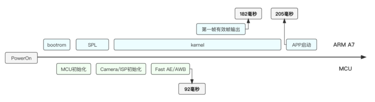
MCU-assisted rapid image convergence:

ARM-stage stream-output flow:

4.2 Driver changes
4.2.1 Kernel driver
- Include these two headers:
#include "../platform/rockchip/isp/rkisp_tb_helper.h"
#include "cam-tb-setup.h"
- Add is_thunderboot to the sensor device structure to identify fast-boot mode.
struct sc200ai {
    ......
    bool            is_thunderboot;
    ......
};
In probe, check CONFIG_VIDEO_ROCKCHIP_THUNDER_BOOT_ISP. When enabled in the kernel, is_thunderboot is true.
sc200ai->is_thunderboot = IS_ENABLED(CONFIG_VIDEO_ROCKCHIP_THUNDER_BOOT_ISP);
- Stream-start/stop interfaces
static int __sc200ai_start_stream(struct sc200ai *sc200ai)
{
    int ret = 0;
    ......
    if (!sc200ai->is_thunderboot) { //⾮快启,写⼊完整寄存器配置
        ret = sc200ai_write_array(sc200ai->client, sc200ai->cur_mode->reg_list);
        if (ret)
            return ret;
        ......
    }

    if (sc200ai->sync_mode == NO_SYNC_MODE)//否则,配置起流
        ret |= sc200ai_write_reg(sc200ai->client, SC200AI_REG_CTRL_MODE,
                     SC200AI_REG_VALUE_08BIT, SC200AI_MODE_STREAMING);
    return ret;
}

static int __sc200ai_stop_stream(struct sc200ai *sc200ai)
{
    int ret = 0;
    sc200ai->has_init_exp = false;

    if (sc200ai->is_thunderboot) {
        sc200ai->is_first_streamoff = true;
        pm_runtime_put(&sc200ai->client->dev);
    }
    ......

    ret |= sc200ai_write_reg(sc200ai->client, SC200AI_REG_CTRL_MODE,
                 SC200AI_REG_VALUE_08BIT, SC200AI_MODE_SW_STANDBY);
    return ret;
}
4.2.2 MCU driver
Refer to camera-driver porting.
4.3 MCU fast-boot configuration
4.3.1 Driver framework
The following sections use SmartSens SC450AI as an example of MCU sensor-driver development on RK.
4.3.1.1 Data types
4.3.1.1.1 struct rk_camera_ops
Description: struct rk_camera_ops defines camera-device operation interfaces. Definition:
struct rk_camera_ops {
    ret_err_t (*init)(struct rk_camera_device *dev);  // 初始化相机设备
    ret_err_t (*open)(struct rk_camera_device *dev, rt_uint16_t oflag);  // 打开相机设备
    ret_err_t (*close)(struct rk_camera_device *dev);  // 关闭相机设备
    ret_err_t (*control)(struct rk_camera_device *dev, int cmd, void *args);  // 控制相机设备
};
Members:
| Member | Description |
|---|---|
| init | Initialize device |
| open | Open device |
| close | Close device |
| control | Control device |
Example:
struct rk_camera_ops rk_sc450ai_ops =
{
    rk_sc450ai_init,
    rk_sc450ai_open,
    NULL,
    rk_sc450ai_control
};
4.3.1.1.2 struct xxx_mode
Description: information about supported sensor modes; add members as required. Definition:
struct xxxx_mode
{
    struct v4l2_fract max_fps;
    uint16_t bus_fmt;
    uint16_t width;
    uint16_t height;
    uint16_t hts_def;
    uint16_t vts_def;
    uint16_t exp_def;
    uint32_t xvclk;
    uint32_t link_freq;
#ifndef REG_LIST_CONVERSION_DEBUG
    const uint8_t *reg_list;
#else
    const struct sc450ai_sensor_reg *reg_list;
#endif
    const int reg_list_size;
    uint8_t hdr_mode;
} __attribute__((__packed__));
Members:
| Member | Description |
|---|---|
| .max_fps | Frame rate: denominator/numerator = fps |
| .bus_fmt | Sensor output format |
| .width | Active width; must match current sensor output width. |
| .height | Active height; must match current sensor output height. |
| .hts_def | Default HTS = active width + HBLANK |
| .vts_def | Default VTS = active height + VBLANK |
| .exp_def | Default exposure time |
| .xvclk | External sensor clock/MCLK |
| .link_freq | MIPI_DPHY sampling frequency in MHz, half the MIPI rate |
| *reg_list | Register list |
| .reg_list_size | Register array size |
| .hdr_mode | Linear, two-frame HDR or three-frame HDR mode |
Example:
static const struct sc450ai_mode supported_modes_4lane[] =
{
    {
        .bus_fmt = MEDIA_BUS_FMT_SBGGR10_1X10,
        .width = 1344,
        .height = 760,
        .max_fps = {
            .numerator = 10000,
            .denominator = 1200000,
        },
        .exp_def = 0x80,
        .hts_def = 0x03a8,
        .vts_def = 0x030c,
        .xvclk = 27000000,
        .link_freq = 360000000,
        .reg_list = g_sc450ai_1344x760_4lane_120fps_reg_table,
        .reg_list_size = ARRAY_SIZE(g_sc450ai_1344x760_4lane_120fps_reg_table),
        .hdr_mode = NO_HDR,
    },
    {/* */},
}
4.3.1.1.3 struct xxx_dev
Description: main camera-device structure containing configuration, status and operation-function pointers. Configured in rk_xxx_init. Definition:
struct xxx_dev
{
    struct rk_camera_device parent;
    char name[RK_CAMERA_DEVICE_NAME_SIZE];
    uint8_t time_valid_delay;
    uint8_t gain_valid_delay;
    char i2c_name[RK_CAMERA_I2C_NAME_SIZE];
    struct rt_i2c_bus_device *i2c_bus;
    uint8_t i2c_addr;
    uint8_t flip;
    struct rt_mutex mutex_lock;
    struct rk_camera_exp_val init_exp;
    uint8_t modes_num;
    const struct sc450ai_mode *supported_modes;
    const struct sc450ai_mode *cur_mode;
    const struct sc450ai_mode *pdst_mode;
    struct sc450ai_mode dst_mode;
    bool has_init_exp;
    bool streaming;
};
Members:
| Member | Description |
|---|---|
| parent | Camera parent device |
| name[RK_CAMERA_DEVICE_NAME_SIZE] | Camera name |
| time_valid_delay | Exposure time takes effect in frame N + time_valid_delay |
| gain_valid_delay | Gain takes effect in frame N + gain_valid_delay |
| i2c_name[RK_CAMERA_I2C_NAME_SIZE] | I2C bus name |
| *i2c_bus | I2C bus device |
| i2c_addr | I2C address |
| flip | Flip/mirror setting |
| mutex_lock | Mutex |
| init_exp | Initial exposure |
| modes_num | Initialization configuration count |
| *supported_modes | Mode list corresponding to lane count //todo (source) |
| *cur_mode | Current mode parameters |
| *dst_mode | Target mode parameters |
| has_init_exp | Whether initial exposure was set |
| streaming | Whether device is streaming |
4.3.1.2 APIs
4.3.1.2.1 rk_xxx_control
Description: generic control interface receiving device-control commands from applications/ISP. Syntax:
ret_err_t rk_sc450ai_control(struct rk_camera_device *dev,
                             dt_cmd_t cmd,
                             void *args);
Parameters:
| Parameter | Description | Direction |
|---|---|---|
| *dev | Camera device descriptor | Input |
| cmd | Camera control command | Input |
| *args | Command arguments | Input |
Return values:
| Return value | Description |
|---|---|
| 0 | Success |
| Nonzero | Failure |
Example:
ret_err_t rk_sc450ai_control(struct rk_camera_device *dev,
                             dt_cmd_t cmd,
                             void *args)
{
    ...
    switch (cmd)
    {
    case RK_DEVICE_CTRL_DEVICE_INIT:
    {
        ret = rk_sc450ai_init(dev);
    }
    break;
    ...
    default:
        sc450ai_dbg("exit CMD %d\n", cmd);
        break;
    }

    return ret;
}
4.3.1.2.2 rk_xxx_init
Description: the controller obtains current camera bus parameters through this interface to determine capture mode. Syntax:
ret_err_t rk_xxx_init(struct rk_camera_device *dev);
Parameters:
| Parameter | Description | Direction |
|---|---|---|
| *dev | Camera device descriptor | Input |
Return values:
| Return value | Description |
|---|---|
| 0 | Success |
| Nonzero | Failure |
4.3.1.2.3 xxx_stream_on
Description: program camera initialization registers; RT_USING_CAM_STREAM_ON_LATE determines whether to enable streaming early. Syntax:
static void xxx_stream_on(struct xxx_dev *dev);
Parameters:
| Parameter | Description | Direction |
|---|---|---|
| *dev | Camera device descriptor | Input |
Return values:
| Return value | Description |
|---|---|
| 0 | Success |
| Nonzero | Failure |
4.3.1.2.4 xxx_stream_off
Description: stop camera streaming. Syntax:
static void xxx_stream_off(struct xxx_dev *dev);
Parameters:
| Parameter | Description | Direction |
|---|---|---|
| *dev | Camera device descriptor | Input |
Return values:
| Return value | Description |
|---|---|
| 0 | Success |
| Nonzero | Failure |
4.3.1.2.5 rk_xxx_get_expinf
Description: get camera exposure information. Syntax:
static ret_err_t rk_xxx_get_expinf(struct xxx_dev *dev, struct rk_camera_exp_info *exp);
Parameters:
| Parameter | Description | Direction |
|---|---|---|
| *dev | Camera device descriptor | Input |
| *exp | Camera exposure parameters | Output |
Return values:
| Return value | Description |
|---|---|
| 0 | Success |
| Nonzero | Failure |
4.3.1.2.6 rk_xxx_set_expval
Description: set camera exposure time and gain. Syntax:
static ret_err_t rk_xxx_set_expval(struct xxx_dev *dev, struct rk_camera_exp_val *exp);
Parameters:
| Parameter | Description | Direction |
|---|---|---|
| *dev | Camera device descriptor | Input |
| *exp | Camera exposure parameters | Input |
Return values:
| Return value | Description |
|---|---|
| 0 | Success |
| Nonzero | Failure |
4.3.1.2.7 rk_xxx_set_vts
Description: set camera VTS. Syntax:
static ret_err_t rk_xxx_set_vts(struct xxx_dev *dev, uint32_t dst_vts);
Parameters:
| Parameter | Description | Direction |
|---|---|---|
| *dev | Camera device descriptor | Input |
| dst_vts | Target VTS | Input |
Return values:
| Return value | Description |
|---|---|
| 0 | Success |
| Nonzero | Failure |
4.3.1.2.8 rk_xxx_get_intput_fmt
Description: get the current camera output format. struct xxx_mode may hold multiple resolutions; initialization chooses one. After set_intput_fmt switches it, get_intput_fmt confirms the active format. Syntax:
static ret_err_t rk_xxx_get_intput_fmt(struct xxx_dev *dev, struct rk_camera_mbus_framefmt
*mbus_fmt);
Parameters:
| Parameter | Description | Direction |
|---|---|---|
| *dev | Camera device descriptor | Input |
| *mbus_fmt | Camera output format | Output |
Return values:
| Return value | Description |
|---|---|
| 0 | Success |
| Nonzero | Failure |
4.3.1.2.9 rk_xxx_set_intput_fmt
Description: set camera output format and controller capture parameters. Syntax:
static ret_err_t rk_xxx_set_intput_fmt(struct xxx_dev *dev, struct rk_camera_mbus_framefmt
*mbus_fmt);
Parameters:
| Parameter | Description | Direction |
|---|---|---|
| *dev | Camera device descriptor | Input |
| *mbus_fmt | Camera output format | Input |
Return values:
| Return value | Description |
|---|---|
| 0 | Success |
| Nonzero | Failure |
4.3.1.2.10 rk_xxx_match_dst_config
Description: traverse supported_modes for the target resolution/output format. Check whether frame rate is reduced and adjust target VTS if so. Syntax:
static ret_err_t rk_xxx_match_dst_config(struct xxx_dev *dev, struct rk_camera_dst_config
*dst_config);
Parameters:
| Parameter | Description | Direction |
|---|---|---|
| *dev | Camera device descriptor | Input |
| *dst_config | Target output format | Input |
Return values:
| Return value | Description |
|---|---|
| 0 | Success |
| Nonzero | Failure |
4.3.1.2.11 rk_xxx_set_flip_mirror
Description: set camera flip/mirror. Syntax:
static ret_err_t rk_xxx_set_flip_mirror(struct xxx_dev *dev, uint32_t flip)
Parameters:
| Parameter | Description | Direction |
|---|---|---|
| *dev | Camera device descriptor | Input |
| flip | 0: neither; 1: Flip only; 2: Mirror only; 3: both | Input |
Return values:
| Return value | Description |
|---|---|
| 0 | Success |
| Nonzero | Failure |
4.3.1.2.12 xxx_stream_on_late
Description: set initial exposure, mirror and flip, then start camera streaming. Syntax:
static void xxx_stream_on_late(struct xxx_dev *dev);
Parameters:
| Parameter | Description | Direction |
|---|---|---|
| *dev | Camera device descriptor | Input |
Return values:
| Return value | Description |
|---|---|
| 0 | Success |
| Nonzero | Failure |
4.3.1.2.13 xxx_quick_stream
Description: enable/disable camera streaming. Syntax:
static void xxx_quick_stream(struct xxx_dev *dev, int on);
Parameters:
| Parameter | Description | Direction |
|---|---|---|
| *dev | Camera device descriptor | Input |
| on | 1: start stream output; 0: stop | Input |
Return values:
| Return value | Description |
|---|---|
| 0 | Success |
| Nonzero | Failure |
4.3.1.2.14 rk_camera_xxx_init
Description: register the sensor I2C device, following the power-up sequence in its datasheet. Syntax:
int rk_xxx_check_sensor_id(struct xxx_dev *dev)
Parameters:
| Parameter | Description | Direction |
|---|---|---|
| *dev | Camera device descriptor | Input |
Return values:
| Return value | Description |
|---|---|
| 0 | Success |
| Nonzero | Failure |
4.3.2 Porting the camera driver
Base a new driver on a similarly specified sensor in rt-thread/bsp/rockchip/camera/ or a nearby model from the same manufacturer.
4.3.2.1 Add build options
Make these additions in rt-thread/bsp/rockchip/common/drivers/Kconfig.
@@ -506,6 +506,8 @@ menu "supported camera"
        bool "Enable GC2053"
    config RT_USING_F37
        bool "Enable F37"
    config RT_USING_SC230AI
        bool "Enable SC230AI"
+   config RT_USING_SC450AI
+       bool "Enable SC450AI"
    config RT_USING_SC850SL
        bool "Enable SC850SL"
4.3.2.2 Register-sequence conversion
Fast-boot MCU sensor drivers initialize through continuous I2C writes. Vendor sequences are generally noncontinuous and must be converted by script into the driver’s continuous-write format.
4.3.2.2.1 Conversion steps
-
Format the initialization sequence according to <sdk>/sysdrv/source/mcu/project/scripts/camera_reg_convert/reg.txt.
-
Replace the contents of <sdk>/sysdrv/source/mcu/project/scripts/camera_reg_convert/reg.txt with the sequence.
-
Convert with this command:
cd <sdk>/sysdrv/source/mcu/project/scripts/camera_reg_convert/
python2 reg_conver.py
- Copy the converted output over the corresponding sensor-driver register sequence. Example:
/*
 * Xclk 27Mhz
 * max_framerate 30fps
 * mipi_datarate per lane 720Mbps, 4lane
 * full resolution
 */
static const uint8_t g_sc450ai_2688x1520_4lane_30fps_reg_table[] =
{
    0x3, 0x01, 0x00, 0x00,
    0x3, 0x36, 0xe9, 0x80,
    0x3, 0x36, 0xf9, 0x80,
    0x3, 0x30, 0x1c, 0x78,
    0x3, 0x30, 0x1f, 0x01,
    0x3, 0x30, 0x2e, 0x00,
    0xa, 0x32, 0x08, 0x0a, 0x80, 0x05, 0xf0, 0x02, 0xee, 0x06, 0x18,
    0x4, 0x32, 0x14, 0x11, 0x11,
    0x8,
};
Continuous-write format: column 1 is the I2C DATA byte count per write; columns 2–3 are the register address; columns 4–n are consecutive register values. The last line gives the total I2C write count. Do not enable streaming inside the sequence; enable it separately in xxx_stream_on_late.
4.3.2.3 Basic functions
Implement every rk_camera_ops function, including all controls in rk_xxx_control, and implement rk_camera_xxx_init.
4.3.3 MCU board configuration
4.3.3.1 CIS (CMOS image sensor) registration
4.3.3.1.1 struct gpio_desc
Definition:
struct gpio_desc
{
    uint32_t gpio_pin;
    struct GPIO_REG *gpio_group;
};
4.3.3.1.2 camera_board_desc
Description: sensor configuration associated with board hardware. Definition:
struct camera_board_desc
{
    struct gpio_desc rst_gpio;
    struct gpio_desc pwdn_gpio;
    struct gpio_desc pwren_gpio;
    eCLOCK_Name mclk_id;
    uint32_t mclk_out_gate_id;
    char isp_subdev_name[RK_CAMERA_DEVICE_NAME_SIZE];
    char i2c_bus[RK_CAMERA_I2C_NAME_SIZE];
    uint8_t i2c_addr;
    uint8_t time_valid_delay;
    uint8_t gain_valid_delay;
    uint8_t mode_id;
    uint32_t width;
    uint32_t height;
    uint32_t pixelcode;
    uint32_t maxfps;
    uint32_t lanes;
    uint32_t hdr_mode;
    uint32_t dst_width;
    uint32_t dst_height;
    uint32_t dst_pixelcode;
    uint32_t dst_maxfps;
    uint32_t dst_hdr_mode;
    bool rst_active;
    bool pwdn_active;
    bool pwren_active;
};
Members:
| Member | Description |
|---|---|
| rst_gpio | Hardware reset pin; follow gpio_desc |
| pwdn_gpio | Low-power pin; follow gpio_desc |
| pwren_gpio | Power-on pin; follow gpio_desc |
| mclk_id | 0 selects mclk0; 1 selects mclk1 |
| isp_subdev_name | Main ISP sensor: RK_ISP_MAIN_SUBDEV_NAME; assist: RK_ISP_ASSIST_SUBDEV_NAME |
| i2c_bus | Select sensor I2C bus |
| i2c_addr | 7-bit sensor I2C address |
| time_valid_delay | Frames before exposure time takes effect |
| gain_valid_delay | Frames before gain takes effect |
| mode_id | Select sensor resolution according to camera.h |
| width | MCU small-image width |
| height | MCU small-image height |
| pixelcode | MCU small-image format |
| maxfps | Maximum FPS across all small-image initialization configurations |
| lanes | Sensor lane count |
| hdr_mode | Small-image HDR (NO_HDR: 0 HDR_X2: 5 HDR_X3: 6) |
| dst_width | MCU large-image width |
| dst_height | MCU large-image height |
| dst_pixelcode | MCU large-image format |
| dst_maxfps | Maximum FPS across all large-image initialization configurations |
| dst_hdr_mode | Large-image HDR (NO_HDR: 0 HDR_X2: 5 HDR_X3: 6) |
| rst_active | Hardware-reset active level |
| pwdn_active | Low-power active level |
| pwren_active | Power-on active level |
4.3.3.1.3 cif_hw_config
data_lanes: sensor lane count. Sensor/csi_dphy/csi_host connections:
| Main camera–DPHY wiring | dphy1.enable | dphy2.enable | csi_host_0.enable | csi_host_1.enable |
|---|---|---|---|---|
| lane0 < - > MIPI_CSI_RX_D0N/P | 1 | 0 | 1 | 0 |
| lane1 < - > MIPI_CSI_RX_D1N/P | 1 | 0 | 1 | 0 |
| lane2 < - > MIPI_CSI_RX_D2N/P | 0 | 1 | 0 | 1 |
| lane3 < - > MIPI_CSI_RX_D3N/P | 0 | 1 | 0 | 1 |
4.3.3.1.4 Single-camera registration
Example:
const struct camera_board_desc camera_sc450ai =
{
    .i2c_addr = 0x30,
    .rst_gpio =
    {
        .gpio_pin = GPIO_PIN_A7,
        .gpio_group = GPIO4,
    },
    .pwdn_gpio =
    {
        .gpio_pin = GPIO_PIN_A2,
        .gpio_group = GPIO4,
    },
    .time_valid_delay = 2,
    .gain_valid_delay = 2,
    .width = 1344,
    .height = 760,
    .maxfps = 120,
    .lanes = 4,
    .pixelcode = MEDIA_BUS_FMT_SBGGR10_1X10,
    .hdr_mode = NO_HDR,
    .dst_width = 2688,
    .dst_height = 1520,
    .dst_maxfps = 60,
    .dst_pixelcode = MEDIA_BUS_FMT_SBGGR10_1X10,
    .dst_hdr_mode = NO_HDR,
    .isp_subdev_name = RK_ISP_MAIN_SUBDEV_NAME,
    .i2c_bus = "i2c3",
    .rst_active = 0,
    .pwdn_active = 1,
    .mclk_id = CLK_MIPI0_OUT2IO,
    .mclk_out_gate_id = CLK_MIPI0_OUT2IO_GATE,
};
void cif_hw_config(void)
{
    struct dphy_board_desc *csi2_dphy = (struct dphy_board_desc *)&csi2_dphy_board;
    struct csi2_board_desc *csi_host_0 = (struct csi2_board_desc *)&csi2_host0_board;
    struct vicap_board_desc *vicap = (struct vicap_board_desc *)&vicap_board;
    csi2_dphy->enable = true;
    csi2_dphy->csi2_dphy1.enable = true;
    csi2_dphy->csi2_dphy1.csi_host_idx = 0;
    csi2_dphy->csi2_dphy1.isp_subdev_name = RK_ISP_MAIN_SUBDEV_NAME;

    csi_host_0->enable = true;

    vicap->enable = true;
}
4.3.4 Add a board configuration
-
Implement camera_board_desc and cif_hw_config in bsp/rockchip/xxx_mcu/board/xxx/board.c. Refer to CIS registration.
-
Add peripheral IOMUX configuration in bsp/rockchip/xxx_mcu/board/xxx/iomux.c according to the schematic.
5. New features
5.1 AOV
AOV (Always On Video) uses sleep/wake cycles for continuous 24-hour low-frame-rate recording. AI detection, PIR or Wi-Fi events can switch it back to normal frame rate.
5.1.1 Scenarios
Three scenarios: normal frame rate for remote preview, PIR events or person detection, requiring recording/networking; AOV low frame rate while idle with sufficient battery, recording the main stream and keeping Wi-Fi/4G alive; low-power keepalive while idle with low battery, powering down the SoC while Wi-Fi/4G stays alive.
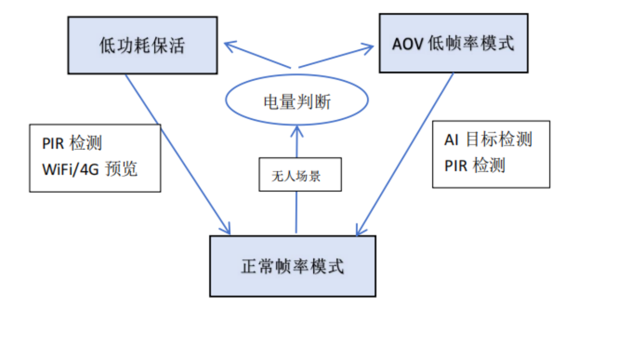
5.1.2 Workflow
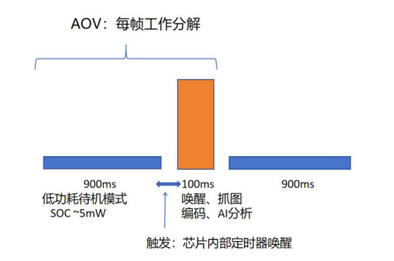
5.1.3 Concepts
AOV uses sensor standby, which can be sleep or reset for lower power. Sleep stops image data, reduces power and retains registers. SC200AI has two sleep-entry methods:
-
Pull PWDN low; I2C reads/writes are unavailable.
-
Write 0 to the stream-control register; I2C remains available. Reset mode stops image data, reduces power and resets all registers. SC200AI has two reset-entry methods:
-
Pull XSHUTDN low; I2C is unavailable.
-
Write 1 to the software-reset enable register; reset lasts 150ns.
5.1.3.1 Hardware standby
Hardware standby pulls PWDN low to put the sensor into low-power sleep; I2C cannot be read/written. For SC200AI add rockchip,camera-module-stb = <1> to the DTS sensor node. Value 1 enables hardware-standby support; 0 means unsupported.
sc200ai: sc200ai@30 {
    compatible = "smartsens,sc200ai";
    status = "okay";
    reg = <0x30>;
    ...
    rockchip,camera-module-stb = <1>;
    port {
        sc200ai_out: endpoint {
            remote-endpoint = <&csi_dphy_input1>;
            data-lanes = <1 2>;
        };
    };
};
Parse this property in probe and store support in sc200ai->standby_hw. If supported, ioctl RKMODULE_SET_QUICK_STREAM drives PWDN GPIO according to stream state. Sleep/wake issues V4L2 ioctl commands to reset exposure/gain registers. Driver reference:
The source references “4.2.4 Driver implementation”, hardware-standby sample.
5.1.3.2 Software standby
After wake-up, software standby rewrites the complete sensor register configuration. In sensor ioctl RKMODULE_SET_QUICK_STREAM it then directly sets the stream register. The source references “4.2.4 Driver implementation”, software-standby sample.
5.1.4 Driver implementation
Hardware-standby reference code:
static long sc200ai_ioctl(struct v4l2_subdev *sd, unsigned int cmd, void *arg)
{
    ......
    switch (cmd) {
    case RKMODULE_SET_QUICK_STREAM:
            stream = *((u32 *)arg);

            if (sc200ai->standby_hw) { // hardware standby
                if (stream) {
                    if (!IS_ERR(sc200ai->pwdn_gpio))
                        gpiod_set_value_cansleep(sc200ai->pwdn_gpio, 1);
                    // Make sure __v4l2_ctrl_handler_setup can be called correctly
                    sc200ai->is_standby = false;
                    ret = sc200ai_write_reg(sc200ai->client, SC200AI_REG_MIPI_CTRL,
                        SC200AI_REG_VALUE_08BIT, SC200AI_MIPI_CTRL_ON);

                    #if IS_REACHABLE(CONFIG_VIDEO_CAM_SLEEP_WAKEUP)
                    if (__v4l2_ctrl_handler_setup(&sc200ai->ctrl_handler))
                        dev_err(&sc200ai->client->dev, "__v4l2_ctrl_handler_setup fail!");
                    if (sc200ai->cur_mode->hdr_mode != NO_HDR) {
                        if (sc200ai->cam_sw_inf) {
                            ret = sc200ai_ioctl(&sc200ai->subdev,
                                        PREISP_CMD_SET_HDRAE_EXP,
                                        &sc200ai->cam_sw_inf->hdr_ae);
                            if (ret) {
                                dev_err(&sc200ai->client->dev,
                                    "init exp fail in hdr mode\n");
                                return ret;
                            }
                        }
                    }
                    #endif

                    ret |= sc200ai_write_reg(sc200ai->client, SC200AI_REG_CTRL_MODE,
                        SC200AI_REG_VALUE_08BIT, SC200AI_MODE_STREAMING);

                    dev_info(&sc200ai->client->dev, "quickstream, streaming on: exit hw
standby mode\n");
                } else {
                    ret = sc200ai_write_reg(sc200ai->client, SC200AI_REG_CTRL_MODE,
                        SC200AI_REG_VALUE_08BIT, SC200AI_MODE_SW_STANDBY);

                    ret |= sc200ai_write_reg(sc200ai->client, SC200AI_REG_MIPI_CTRL,
                        SC200AI_REG_VALUE_08BIT, SC200AI_MIPI_CTRL_OFF);

                    if (!IS_ERR(sc200ai->pwdn_gpio))
                        gpiod_set_value_cansleep(sc200ai->pwdn_gpio, 0);

                    dev_info(&sc200ai->client->dev, "quickstream, streaming off: enter hw
standby mode\n");
                    sc200ai->is_standby = true;
                }
            }
        ......
}
Software-standby reference implementation:
static long sc200ai_ioctl(struct v4l2_subdev *sd, unsigned int cmd, void *arg)
{
    ......
    switch (cmd) {
    case RKMODULE_SET_QUICK_STREAM:
            stream = *((u32 *)arg);
            ......
            else {  // software standby
            if (stream) {
                ret = sc200ai_write_reg(sc200ai->client, SC200AI_REG_MIPI_CTRL,
                    SC200AI_REG_VALUE_08BIT, SC200AI_MIPI_CTRL_ON);

                ret |= sc200ai_write_reg(sc200ai->client, SC200AI_REG_CTRL_MODE,
                    SC200AI_REG_VALUE_08BIT, SC200AI_MODE_STREAMING);
                dev_info(&sc200ai->client->dev, "quickstream, streaming on: exit soft
standby mode\n");
            } else {
                ret = sc200ai_write_reg(sc200ai->client, SC200AI_REG_CTRL_MODE,
                    SC200AI_REG_VALUE_08BIT, SC200AI_MODE_SW_STANDBY);

                ret |= sc200ai_write_reg(sc200ai->client, SC200AI_REG_MIPI_CTRL,
                    SC200AI_REG_VALUE_08BIT, SC200AI_MIPI_CTRL_OFF);
                dev_info(&sc200ai->client->dev, "quickstream, streaming off: enter soft
standby mode\n");
            }
        }

        break;
        ......
    }
5.1.5 References
For AOV development see Rockchip_Trouble_Shooting_Linux5.10_Camera_CN.pdf and Rockchip_RV1106_Developer_Guide_Linux_AOV_CN.pdf.
5.2 Synchronization (master/slave)
One sensor is generally a simple Master. Two or more sensors requiring synchronized streaming/exposure need control-mode configuration, normally master/slave as appropriate. The following applications require simultaneous exposure/output with strict temporal alignment:
| Member | Description |
|---|---|
| 3D / binocular / stereo vision | Mandatory synchronization; otherwise incorrect depth. |
| Multicamera stitching / panorama | Frame synchronization for precise alignment. |
| Machine vision / industrial inspection | Synchronized sampling across viewpoints. |
| Autonomous driving / ADAS | Temporal synchronization is critical. |
| Video conferencing / multiple cameras | Strict synchronization usually unnecessary, but improves experience. |
A common method is a global FSYNC/EFSYNC/TRIGGER/SYNC_IN signal. The host SoC triggers all sensors together to start exposure/readout simultaneously, aligning all image streams in time.
5.2.1 Sensor Slave mode
Slave mode means an external MCU/SoC/DSP drives sensor communication, timing and transfer through clocks, sync signals and I2C/MIPI controls. The sensor responds instead of initiating timing/communication. In a multisensor system a SoC/FPGA sends FSYNC to all sensors simultaneously; they begin exposure or frame readout together for matching timestamps and synchronized content.
| Member | Description |
|---|---|
| FSYNC (Frame SYNC) | Frame-sync input: external digital signal, normally GPIO/CMOS level, tells multiple sensors to begin exposure/readout together. |
| EFSYNC (External Frame SYNC) | External frame sync, manufacturer naming varies. Like FSYNC: host sends, all Slave sensors receive and act synchronously. |
| TRIGGER / SYNC_IN / STROBE | Alternative sensor names for external-trigger synchronization inputs. |
RK multicamera synchronization currently configures one Master and the others as Slaves. After the Master frame completes, arrival of external FSYNC/EFSYNC starts the Slave sensors’ exposure/readout together for temporal alignment.
5.2.2 Driver implementation
- Obtain master/slave register settings from the datasheet or manufacturer FAE.
/* sync mode regs */
static __maybe_unused const struct regval sc200ai_interal_sync_master_start_regs[] = {
    {0x300a, 0x24}, //sync as output PAD
    {0x3032, 0xa0},
    {0x3222, 0x00}, //master mode
    {0x3216, 0x00},
    {0x3217, 0x04},
    {REG_NULL, 0x00},
};

static __maybe_unused const struct regval sc200ai_interal_sync_master_stop_regs[] = {
    {REG_NULL, 0x00},
};

static __maybe_unused const struct regval sc200ai_interal_sync_slaver_start_regs[] = {
    {0x3222, 0x02}, //slave mode
    {0x3230, 0x00},
    {0x3231, 0x04}, //Rows Before Read
    {0x3224, 0x82}, //fsync trigger
    {REG_NULL, 0x00},
};

static __maybe_unused const struct regval sc200ai_interal_sync_slaver_stop_regs[] = {
    {REG_NULL, 0x00},
};
- Add synchronization-mode variables
struct sc200ai {
    ......
    enum rkmodule_sync_mode sync_mode;
    ......
};
Common synchronization-mode definitions:
/*
 * sensor exposure sync mode
 */
enum rkmodule_sync_mode {
    NO_SYNC_MODE = 0,
    EXTERNAL_MASTER_MODE,
    INTERNAL_MASTER_MODE,
    SLAVE_MODE,
    SOFT_SYNC_MODE,
};
Parse synchronization properties in the DTS sensor node to determine its active mode.
static int sc200ai_probe(struct i2c_client *client,
             const struct i2c_device_id *id)
    ......
    ret = of_property_read_string(node, RKMODULE_CAMERA_SYNC_MODE,
                      &sync_mode_name);
    if (ret) {
        sc200ai->sync_mode = NO_SYNC_MODE;
        dev_err(dev, "could not get sync mode!\n");
    } else {
        if (strcmp(sync_mode_name, RKMODULE_EXTERNAL_MASTER_MODE) == 0) {
            sc200ai->sync_mode = EXTERNAL_MASTER_MODE;
            dev_info(dev, "sync_mode = [EXTERNAL_MASTER_MODE]\n");
        } else if (strcmp(sync_mode_name, RKMODULE_INTERNAL_MASTER_MODE) == 0) {
            sc200ai->sync_mode = INTERNAL_MASTER_MODE;
            dev_info(dev, "sync_mode = [INTERNAL_MASTER_MODE]\n");
        } else if (strcmp(sync_mode_name, RKMODULE_SLAVE_MODE) == 0) {
            sc200ai->sync_mode = SLAVE_MODE;
            dev_info(dev, "sync_mode = [SLAVE_MODE]\n");
        } else if (strcmp(sync_mode_name, RKMODULE_SOFT_SYNC_MODE) == 0) {
            sc200ai->sync_mode = SOFT_SYNC_MODE;
            dev_info(dev, "sync_mode = [SOFT_SYNC_MODE]\n");
        } else {
            dev_info(dev, "sync_mode = [NO_SYNC_MODE]\n");
        }
    }
    ......
Related macros:
#define RKMODULE_CAMERA_SYNC_MODE       "rockchip,camera-module-sync-mode"
#define RKMODULE_INTERNAL_MASTER_MODE   "internal_master"
#define RKMODULE_EXTERNAL_MASTER_MODE   "external_master"
#define RKMODULE_SLAVE_MODE             "slave"
#define RKMODULE_SOFT_SYNC_MODE         "soft_sync"
- At stream start, program different registers according to the sensor synchronization mode.
static int __sc200ai_start_stream(struct sc200ai *sc200ai)
{
    int ret = 0;
    ......
    if (!sc200ai->is_thunderboot) {
        ret = sc200ai_write_array(sc200ai->client, sc200ai->cur_mode->reg_list);
        if (ret)
            return ret;

        ......

        if (sc200ai->sync_mode == INTERNAL_MASTER_MODE ||
            sc200ai->sync_mode == SOFT_SYNC_MODE) {
            ret |= sc200ai_write_array(sc200ai->client,
                           sc200ai_interal_sync_master_start_regs);
        } else if (sc200ai->sync_mode == EXTERNAL_MASTER_MODE) {
            ret |= sc200ai_write_array(sc200ai->client,
                           sc200ai_interal_sync_slaver_start_regs);
        } else if (sc200ai->sync_mode == SLAVE_MODE) {
            ret |= sc200ai_write_array(sc200ai->client,
                           sc200ai_interal_sync_slaver_start_regs);
        }
        if (ret) {
            dev_err(&sc200ai->client->dev,
                "write sync regs failed\n");
            return ret;
        }
    }

    if (sc200ai->sync_mode == NO_SYNC_MODE)
        ret |= sc200ai_write_reg(sc200ai->client, SC200AI_REG_CTRL_MODE,
                     SC200AI_REG_VALUE_08BIT, SC200AI_MODE_STREAMING);
    return ret;
}
- Set/get synchronization mode in RKAIQ. If DTS does not configure sensor synchronization, RKAIQ interfaces can set multicamera synchronization through ioctl.
static long sc200ai_ioctl(struct v4l2_subdev *sd, unsigned int cmd, void *arg)
{
    ......
    case RKMODULE_GET_SYNC_MODE:
        sync_mode = (u32 *)arg;
        *sync_mode = sc200ai->sync_mode;
        break;
    case RKMODULE_SET_SYNC_MODE:
        sync_mode = (u32 *)arg;
        if (sync_mode) {
            sc200ai->sync_mode = *sync_mode;
            dev_info(&sc200ai->client->dev, "set sync mode is: %s\n",
                 ((*sync_mode == EXTERNAL_MASTER_MODE) ||
                  (*sync_mode == SLAVE_MODE)) ? "secondary" : "primary");
        } else {
            dev_info(&sc200ai->client->dev, "set sync mode is: NO_SYNC_MODE\n");
        }
        break;
    ......
}
5.3 Flash control
The sensor driver can control PWM or GPIO flash units. Configure the relevant parameters correctly for application-layer flash on/off control.
5.3.1 Driver implementation
- Header
#include "light_ctl.h"
- Add control variables
struct xxxx {
    ......
    bool                    enable_light_ctl;
    struct rk_light_param   light_param;
    ......
};
- Handle ioctl RKCIS_CMD_FLASH_LIGHT_CTRL
static long xxxx_ioctl(struct v4l2_subdev *sd, unsigned int cmd, void *arg)
    ......
    struct rk_light_param *light_param;
    ......
    case RKCIS_CMD_FLASH_LIGHT_CTRL:
        dev_info(&mis5001->client->dev, "set flash light param\n");
        light_param = (struct rk_light_param *)arg;
        if (light_param->light_enable) {
            memcpy(&mis5001->light_param, light_param, sizeof(struct rk_light_param));
            mis5001->enable_light_ctl = true;
        } else {
            mis5001->enable_light_ctl = false;
        }
        ret = light_ctl_write(mis5001->module_index, light_param);
        break;

    ......
};

static long xxxx_compat_ioctl32(struct v4l2_subdev *sd,
                   unsigned int cmd, unsigned long arg)
{
        ......
        struct rk_light_param *light_param;
        ......
        switch (cmd) {
        ......
        case RKCIS_CMD_FLASH_LIGHT_CTRL:
            light_param = kzalloc(sizeof(*light_param), GFP_KERNEL);
            if (!light_param) {
                ret = -ENOMEM;
                return ret;
            }

            ret = copy_from_user(light_param, up, sizeof(*light_param));
            if (!ret)
                ret = mis5001_ioctl(sd, cmd, light_param);
            else
                ret = -EFAULT;
            kfree(light_param);
            break;
        }
        .....
}
5.3.2 References
See section 7.2, illumination-light control, in Rockchip_Trouble_Shooting_Linux5.10_Camera_CN.pdf for implementation details.
5.4 Resolution switching
Applications may use different sensor resolutions in different scenarios. The driver responds to upper-layer commands to switch resolution.
5.4.1 Driver implementation
Reference code:
static int sc200ai_set_setting(struct sc200ai *sc200ai, struct rk_sensor_setting *setting)
{
    int i = 0;
    int cur_fps = 0;
    s64 h_blank, vblank_def;
    u64 pixel_rate = 0;
    const struct sc200ai_mode *mode = NULL;
    const struct sc200ai_mode *match = NULL;

    dev_info(&sc200ai->client->dev,
        "sensor setting: %d x %d, fps:%d fmt:%d, mode:%d\n",
        setting->width, setting->height,
        setting->fps, setting->fmt, setting->mode);

    for (i = 0; i < ARRAY_SIZE(supported_modes); i++) {
        mode = &supported_modes[i];
        if (mode->width == setting->width &&
            mode->height == setting->height &&
            mode->hdr_mode == setting->mode &&
            mode->bus_fmt == setting->fmt) {
            cur_fps = DIV_ROUND_CLOSEST(mode->max_fps.denominator, mode->max_fps.numerator);
            if (cur_fps == setting->fps) {
                match = mode;
                break;
            }
        }
    }

    if (match) {
        dev_info(&sc200ai->client->dev, "-----%s: match the support mode, mode idx:%d-----
\n",
            __func__, i);
        sc200ai->cur_mode = mode;

        h_blank = mode->hts_def - mode->width;
        __v4l2_ctrl_modify_range(sc200ai->hblank, h_blank,
                     h_blank, 1, h_blank);
        vblank_def = mode->vts_def - mode->height;
        __v4l2_ctrl_modify_range(sc200ai->vblank, vblank_def,
                     SC200AI_VTS_MAX - mode->height,
                     1, vblank_def);
        __v4l2_ctrl_s_ctrl(sc200ai->link_freq, mode->mipi_freq_idx);
        pixel_rate = (u32)link_freq_menu_items[mode->mipi_freq_idx] /
                 mode->bpp * 2 * SC200AI_LANES;
        __v4l2_ctrl_s_ctrl_int64(sc200ai->pixel_rate, pixel_rate);
        dev_info(&sc200ai->client->dev, "freq_idx:%d pixel_rate:%lld\n",
            mode->mipi_freq_idx, pixel_rate);
        sc200ai->cur_vts = mode->vts_def;
        sc200ai->cur_fps = mode->max_fps;

        dev_info(&sc200ai->client->dev, "hts_def:%d cur_vts:%d cur_fps:%d\n",
            mode->hts_def, mode->vts_def,
            sc200ai->cur_fps.denominator / sc200ai->cur_fps.numerator);
    } else {
        dev_err(&sc200ai->client->dev, "couldn't match the support modes\n");
        return -EINVAL;
    }

    return 0;
}

static long sc200ai_ioctl(struct v4l2_subdev *sd, unsigned int cmd, void *arg)
    ......
    struct rk_sensor_setting *setting;
    ......

    switch (cmd) {
    ......
    case RKCIS_CMD_SELECT_SETTING:
        setting = (struct rk_sensor_setting *)arg;
        ret = sc200ai_set_setting(sc200ai, setting);
        break;

    ......
    }
}
5.5 Supporting multiple lane configurations
Host platform, sensor count, performance and wiring may require register sequences for different lane counts. The driver supports this compatibility.
5.5.1 Driver implementation
Reference code:
// 4 Lane 寄存器配置⽀持列表
static const struct sc450ai_mode supported_modes_4lane[] = {
    {
        ...
    },
    {
        ...
    },
};
// 2 Lane 寄存器配置⽀持列表
static const struct sc450ai_mode supported_modes_2lane[] = {
    {
        ...
    },
    {
        ...
    },
}
static int sc450ai_probe(struct i2c_client *client,
             const struct i2c_device_id *id)
{
    struct device_node *node = dev->of_node;
    struct device_node *endpoint;
    ......
    endpoint = of_graph_get_next_endpoint(dev->of_node, NULL);
    if (!endpoint) {
        dev_err(dev, "Failed to get endpoint\n");
        return -EINVAL;
    }
    ret = v4l2_fwnode_endpoint_parse(of_fwnode_handle(endpoint),
        &sc450ai->bus_cfg);
    of_node_put(endpoint);
    if (ret) {
        dev_err(dev, "Failed to get bus config\n");
        return -EINVAL;
    }

    // 根据dts配置的lane数选择不同的寄存器⽀持列表数组
    if (sc450ai->bus_cfg.bus.mipi_csi2.num_data_lanes == 4) {
        sc450ai->supported_modes = supported_modes_4lane;
        sc450ai->cfg_num = ARRAY_SIZE(supported_modes_4lane);
        dev_info(dev, "detect sc450ai lane: %d\n",
             sc450ai->bus_cfg.bus.mipi_csi2.num_data_lanes);
    } else {
        sc450ai->supported_modes = supported_modes_2lane;
        sc450ai->cfg_num = ARRAY_SIZE(supported_modes_2lane);
        dev_info(dev, "detect sc450ai lane: %d\n",
             sc450ai->bus_cfg.bus.mipi_csi2.num_data_lanes);
    }
    ......
}
For 2Lane/4Lane supported_modes, probe parses the DTS lane count into bus_cfg.bus.mipi_csi2.num_data_lanes and initializes the corresponding mode list and cfg_num count.
5.6 Other
6. Troubleshooting
6.1 Sensor unrecognized, probe or I2C failure
The source attributes an unrecognized sensor ID to power-up-sequence requirements rather than RKISP/RKCIF. Check in this order:
-
Correct 7-bit I2C slave ID, not an 8-bit value.
-
MCLK output and correct amplitude; normally 24Mhz, sometimes 27Mhz.
-
Required power-up sequence: avdd, dovdd and dvdd within datasheet specifications, correct PWDN/RESET GPIO configuration.
6.1.1 MCLK/VDD cannot be measured
Drivers normally enable MCLK/power only when needed, leaving them off after boot. For debugging, the source suggests temporarily commenting out power_off() so power remains on for measurement. Check oscilloscope bandwidth; at least 48M is recommended.
-
Incorrect MCLK enable: refer to drivers/media/i2c/ov5695.c.
-
GPIO occupied by another module: kernel logs normally report this. The io command can inspect pin-ctrl register settings.
6.1.2 Verify sensor power-up sequencing
Use an oscilloscope to check each supply’s sequence and delays against the datasheet. Some sensors, e.g. ov5695, have no required VDD ordering and use regulator_bulk. Others, e.g. ov2685.c, need ordered individual regulators such as avdd_regulator and dovdd_regulator. Choose according to actual requirements.
6.2 Default exp_def, hts_def and vts_def values
Ask the sensor manufacturer if possible. Otherwise locate the registers in the datasheet and read their initialization values from the register list. SC200AI example:
#define SC200AI_REG_VTS_H       0x320e
#define SC200AI_REG_VTS_L       0x320f
...
static const struct regval sc200ai_linear_10_1920x1080_30fps_regs[] = {
    ...
    //HTS=1100*2=2200
    {0x320c, 0x04},
    {0x320d, 0x4c},
    //VTS=1125
    {0x320e, 0x04},
    {0x320f, 0x65},
    ...
};

static const struct sc200ai_mode supported_modes[] = {
    {
        .width = 1920,
        .height = 1080,
        .max_fps = {
            .numerator = 10000,
            .denominator = 300000,
        },
        .exp_def = 0x0080,  // exp曝光默认值,⼀般应⼩于vts默认值,最⼤vts_def - 8 (曝光⾏,具体减去
多少,参考 Sensor ⼿册,可能4/8/10)
        .hts_def = 0x44C * 2,// hts默认值填写对应寄存器列表中给出的默认值(可乘倍数)
        .vts_def = 0x0465,  // vts默认值填对应寄存器列表中给出的默认值
        ...
    },
    ...
};
6.3 link_freq and pixel_rate values
link_freq is the actual MIPI clock frequency, not the 24M MCLK but MIPI dn/dp clk. Prefer manufacturer information or datasheet parameters. Generally the actual value is no lower than the following result in Hz:
link_freq = width * height * fps * bits_per_pixel / lanes / 2
If link_freq is unknown, measure with an oscilloscope. pixel_rate is pixels transferred per second; after determining link_freq, calculate it as follows:
pclk = link_freq * 2 * lanes / bits_per_pixel
6.4 When is a sensor operational?
First verify sensor ID and I2C read/write operation. media-ctl -p -d /dev/media0 should show name, resolution and other sensor information:
# media-ctl -p -d /dev/media0 | tail -n 30
                -> "rkcif_tools_id2":0 []
        pad11: Source
                -> "stream_cif_mipi_id0":0 []
                -> "stream_cif_mipi_id1":0 []
                -> "stream_cif_mipi_id2":0 []
                -> "stream_cif_mipi_id3":0 []
                -> "rkcif_scale_ch0":0 []
                -> "rkcif_scale_ch1":0 []
                -> "rkcif_scale_ch2":0 []
                -> "rkcif_scale_ch3":0 []
                -> "rkcif_tools_id0":0 []
                -> "rkcif_tools_id1":0 []
                -> "rkcif_tools_id2":0 [ENABLED]

- entity 58: rockchip-csi2-dphy0 (2 pads, 2 links)
             type V4L2 subdev subtype Unknown flags 0
             device node name /dev/v4l-subdev1
        pad0: Sink
                [fmt:SBGGR10_1X10/1920x1080@10000/300000 field:none]
                <- "m00_b_sc200ai 4-0030":0 [ENABLED]
        pad1: Source
                -> "rockchip-mipi-csi2":0 [ENABLED]

- entity 63: m00_b_sc200ai 4-0030 (1 pad, 1 link)
             type V4L2 subdev subtype Sensor flags 0
             device node name /dev/v4l-subdev2
        pad0: Source
                [fmt:SBGGR10_1X10/1920x1080@10000/300000 field:none]
                -> "rockchip-csi2-dphy0":0 [ENABLED]
If media-ctl/v4l2-ctl were not packaged, use dmesg to inspect successful sensor detection in kernel logs. During capture, MIPI must output data without MIPI/ISP errors and the application must receive frames.
6.5 Streaming with CRC/ECC errors
6.5.1 Identify error source and log details
Search dmesg/kernel logs precisely for ERR1, ERR2, CRC, ECC, mipi, csi2 and phy. Rockchip CSI/PHY drivers normally print detailed register states on errors. Record ERR1/ERR2 error codes and VC (Virtual Channel) numbers. Typical log:
[  126.741234] rockchip-mipi-csi2 feaa0000.csi2-dphy: ERR1: 0x00000040 (ECC Error,
VC1), FIFO overflow? Check timings!
[  126.741259] rockchip-mipi-csi2 feaa0000.csi2-dphy: ERR2: 0x00000010 (CRC Error,
VC0)
Error types: ERR1 (CSIS_ERR1) often indicates protocol errors such as ECC, frame format or packet-header checks. ERR2 (CSIS_ERR2) often indicates transport errors: receiver FIFO overflow, timeout or sync-code errors. CRC Error means packet checksum mismatch/bit flips. ECC Error means failed header error detection/correction, usually more serious and pointing to the physical layer. Overflow is receiver FIFO overflow, usually timing mismatch.
6.5.2 Software configuration (driver/DTS)
Match sensor timing: driver HTS (Total Width) and VTS (Total Height) must match the SoC CSI2-DPHY receiver configuration. A mismatch can cause FIFO overflow (ERR2 Overflow). Verify with:
media-ctl -p -d /dev/mediaX  # 查看 Entity 之间的链路和当前格式
v4l2-ctl -d /dev/v4l-subdevY --get-fmt-video # 查看 Sensor 输出格式
v4l2-ctl -d /dev/v4l-subdevZ --get-fmt-video # 查看 CSI-DPHY 输⼊格式
Keep the sensor MIPI output rate within the SoC CSI-DPHY maximum; the source lists approximately 2.5Gbps/lane for RK3566 and RK3588. The sensor MIPI VC number (e.g. 0/1) must match csi2_dphy or rkcif_mipi_lvds in DTS; the source associates mismatches with CRC errors. Verify the csi2_dphy node:
csi2_dphy_hw: csi2-dphy@fedc0000 {
    compatible = "rockchip,rk3588-csi2-dphy-hw";
    clocks = ...; // 时钟配置必须正确
    resets = ...;
    rockchip,hw = <&csi2_dphy0>; // 硬件版本
};
csi2_dphy0: csi2-dphy0 {
    compatible = "rockchip,rk3568-csi2-dphy";
    phys = <&mipi_dphy0>; // 指向正确的PHY
    phy-names = "dphy";
    ports {
        port@0 {
            reg = <0>;
            #address-cells = <1>;
            #size-cells = <0>;
            // 关键点: CSI 接收 VC 设置
            endpoint {
                remote-endpoint = <&sensor_out>;
                data-lanes = <1 2 3 4>; // Lane数量必须匹配Sensor
                virtual-channel-index = <0>; // 必须等于Sensor输出VC
            };
        };
    };
};
Check clock/power: correct, conflict-free sensor, MIPI DPHY and CSI2 Host Controller frequencies. DOVDD/AVDD/DVDD must remain within specifications; measure ripple <50mV with an oscilloscope.
6.5.3 Hardware link (source claims over 90% physical-layer problems)
Physical connections: reseat and lock the FPC, then test a known-good replacement. Inspect contacts for oxidation/contamination and clean with precision electronics cleaner. The source specifies differential impedance 100Ω ±10%; poor cables are a common cause.
Signal integrity requires an oscilloscope/protocol analyzer. Measure every sensor supply, especially 1.2V/1.8V DVDD, for noise <50mV pk-pk. At sensor CLK+/CLK- and DATA+/DATA- test points, the source gives: eye height ≥100mV, eye width ≥0.4 UI and monotonic clear edges (closed/blurred eyes are critical); slew rate 1.5–4V/ns depending on D-PHY version; overshoot/ringing <20% Vdiff pp; common-mode noise <100mV; data-to-clock skew <0.3 UI. Try a low MIPI rate such as 500Mbps and see whether errors disappear.
Check MCLK, usually 24MHz/27MHz: frequency stability ±50ppm, phase jitter <50ps RMS. Use shielded cables and minimize probe ground loops. The source gives sensor-board to SoC-board ground impedance <1Ω. Keep away from Wi-Fi/DC-DC high-frequency circuits, motors and strong magnetic fields.
6.5.4 System validation/debugging
Check data-lanes order/count in DTS against physical wiring, especially lane polarity inversion and lane-polarities settings. Reduce output to e.g. 320x240 @10fps; disappearing errors suggest bandwidth/signal-quality limits. Enable internal Color Bar/Checkerboard to bypass analog capture and test MIPI directly. Enable rkisp_3A_server in /etc/init.d/ for detailed RK ISP logs. Monitor with v4l2-ctl:
v4l2-ctl -d /dev/video0 --stream-mmap --stream-count=100 --stream-skip=100
Temperature: high temperature degrades signal quality. Observe whether error rate rises with temperature (source example: ambient >85°C).
6.5.5 Emergency troubleshooting strategies
-
Reduce MIPI rate first, to <1.5Gbps/lane for testing.
-
Try only 1 lane.
-
Remove unrelated peripherals and reduce CPU/GPU clocks to isolate interference.
-
Replace sensor module, core board or motherboard, especially if PCB impedance is suspect.
6.5.6 Typical corrective measures
Physical-layer issues (source: 90%): replace with high-quality 100Ω±5% MIPI cable; shorten PCB differential traces, remove via stubs and increase pair spacing; the source also suggests 50Ω termination to ground. Software issues (source: 9%): precisely match VTS, HTS and Pixel Clock; fix VC index/lane mapping; update driver/firmware, particularly MIPI PHY firmware.
Hardware-design defects (source: 1%): redesign power distribution and add LDO filtering; use a high-precision crystal/clock buffer; improve ESD protection/TVS selection.
6.5.7 Sensor index
Set rockchip,camera-module-index in DTS. librkaiq and rockit prefer sensor index as device index; tuning tool_server also finds devices this way. Tools without an explicit -d use 0. Recommended indexes: single camera 0; two cameras 0/1; multiple 0/1/2/3…
7. Reference documents
Writing the sensor driver is only one step. For platform DTS configuration, fast boot/AOV products or image-output problems, consult:
-
Rockchip_Driver_Guide_VI_CN.pdf, last ver: v1.2.0
-
Rockchip Quick Start For Camera.pdf, last ver: v1.0.0
-
Rockchip_Trouble_Shooting_Linux5.10_Camera_CN.pdf
-
Rockchip_Developer_Guide_Linux_AOV_CN.pdf
8. Appendices
8.1 CIS V4L2 controls
| Member | Description |
|---|---|
| V4L2_CID_VBLANK | Vertical blanking: idle period after each frame with no image data. Unit: lines. Each line is image width plus horizontal blanking at V4L2_CID_PIXEL_RATE in the same subdevice. |
| Member | Description |
|---|---|
| V4L2_CID_HBLANK | Horizontal blanking: idle period after every image-data line without output. Unit: pixels. |
| V4L2_CID_EXPOSURE | Sensor exposure time, limited by frame interval. |
| V4L2_CID_ANALOGUE_GAIN | Gain affecting all color components in the pixel matrix, applied in the analog domain before A/D conversion. |
| V4L2_CID_PIXEL_RATE | Read-only pixel rate at subdev source pads, pixels/second. MIPI example: pixel_rate = link_freq * 2 * nr_of_lanes / bits_per_sample |
| V4L2_CID_LINK_FREQ | Data-bus frequency in Hz. Together with media-bus pixel code and bus type (clocks/sample), it defines V4L2_CID_PIXEL_RATE in the pixel array or elsewhere for nonsensors. Frame rate follows pixel clock, image width/height and horizontal/vertical blanking. A pixel-rate control outside the pixel-array subdev is insufficient to calculate frame rate: only at the array are blanking values exact, because no other blanking is allowed there. Select frame rate through desired horizontal/vertical blanking. |
8.2 MEDIA_BUS_FMT list
| CIS sensor type | Sensor output format |
|---|---|
| Bayer RAW | MEDIA_BUS_FMT_SBGGR10_1X10 MEDIA_BUS_FMT_SRGGB10_1X10 MEDIA_BUS_FMT_SGBRG10_1X10 MEDIA_BUS_FMT_SGRBG10_1X10 MEDIA_BUS_FMT_SRGGB12_1X12 MEDIA_BUS_FMT_SBGGR12_1X12 MEDIA_BUS_FMT_SGBRG12_1X12 MEDIA_BUS_FMT_SGRBG12_1X12 MEDIA_BUS_FMT_SRGGB8_1X8 MEDIA_BUS_FMT_SBGGR8_1X8 MEDIA_BUS_FMT_SGBRG8_1X8 MEDIA_BUS_FMT_SGRBG8_1X8 |
| YUV | MEDIA_BUS_FMT_YUYV8_2X8 MEDIA_BUS_FMT_YVYU8_2X8 MEDIA_BUS_FMT_UYVY8_2X8 MEDIA_BUS_FMT_VYUY8_2X8 MEDIA_BUS_FMT_YUYV10_2X10 MEDIA_BUS_FMT_YVYU10_2X10 MEDIA_BUS_FMT_UYVY10_2X10 MEDIA_BUS_FMT_VYUY10_2X10 MEDIA_BUS_FMT_YUYV12_2X12 MEDIA_BUS_FMT_YVYU12_2X12 MEDIA_BUS_FMT_UYVY12_2X12 MEDIA_BUS_FMT_VYUY12_2X12 |
| Only Y (monochrome), raw BW sensor | MEDIA_BUS_FMT_Y8_1X8 MEDIA_BUS_FMT_Y10_1X10 MEDIA_BUS_FMT_Y12_1X12 |
8.3 Camera reference drivers
| CIS data interface | CIS output data type | Frame/Field | Reference drivers |
|---|---|---|---|
| MIPI | Bayer RAW | frame | 0.3M ov7750.c gc0403.c 0.9M jx_h62.c jx_h63p 1.2M ov9750.c jx-h65.c mia1321.c 2M jx_f37.c mis20s1.c mis2031.c ov2685.c ov2680.c ov2735.c ov02g10.c ov02b10.c gc2385.c gc2355.c gc2053.c gc2093.c sc2232.c sc2239.c sc223a.c sc2310.c sc2336.c sc2336p.c sc230ai.c sc231hai.c sc235hai.c sc210iot.c sp250a.c 4M gc4c33.c jx_k04.c jx_k17.c mis4001.c mis40c1.c mis40h1.c ov4686.c ov4688.c ov4689.c os04c10.c os04a10.c sc401ai.c sc4236.c sc450ai.c sc485sl.c imx347.c 5M mis5001.c os05a20.c ov5695.c ov5648.c ov5670.c gc5024.c gc5025.c gc5035.c hm5040.c sc5239.c hynix_hi556.c 8M ar0822.c gc8613.c mis8001.c ov8858.c os08a10.c os08a20.c sc8220.c sc830ai.c sc835hai.c sc850sl.c imx378.c imx317.c imx219.c gc8034.c hynix_hi846.c s5kgm1sp.c s5k4h7yx.c 13M ov13850.c ov13b10.c imx258.c ov12d2q.c |
| MIPI | Bayer raw hdr | frame | 2M imx307.c imx327.c imx462.c gc2093.c ov02k10.c ov2718.c sc200ai.c sc2310.c jx-f37.c 4M ov4689.c os04a10.c imx347.c imx464.c sc4238.c 5M imx335.c os05a20.c sc500ai.c 8M imx334.c imx415.c |
| MIPI | YUV | frame | 2M gc2145.c |
| MIPI | RAW BW | frame | 0.3M ov7251.c 1M ov9281.c 1.3M sc132gs.c |
| MIPI | YUV | field | tc35874x.c |
| ITU.BT60 | Bayer RAW | 2M imx323.c ar0230.c |
|
| ITU.BT601 | YUV | 0.3M gc0329.c gc0312.c gc032a.c 2M gc2145.c gc2155.c gc2035.c bf3925.c |
|
| ITU.BT601 | RAW BW | 0.3M sc031gs.c 1.3M sc032gs.c |
|
| ITU.BT656 | Bayer RAW | 2M imx323.c (can be supported) |