
Complete technical content from Rockchip RK3399 USB V2.0.0, Chinese and English editions. Scope: RK3399, Linux 4.4+. This is an ArmSoM platform reference, not a claim of support on every board. Verify the board, SDK/BSP, kernel branch, USB/DP pins, VBUS supply and Type-C controller. No ArmSoM hardware validation was performed; results and outputs are source examples. Chinese uses Chinese original figures; English, Russian and German use English original figures.
Source overview: this guide explains RK3399 USB DTS configuration and use across Linux kernel versions. RK3399 has two Type-C interfaces supporting USB 3.1 Gen1 and DisplayPort, plus two USB 2.0 Host interfaces. Each Type-C interface has its own USB 3.1 Gen1 OTG controller supporting Peripheral and Host, with USB2.0/1.1/1.0 backward compatibility. Products can simplify these to Type-A USB 3.0/2.0 + DP, Micro USB 3.0/2.0 and other physical interfaces. Kernel drivers support common hardware designs, but USB DTS must match the actual circuit.
Support and debugging statuses describe the source-document period, not the current SDK. Power and wiring must comply with component ratings. Commands require review and an adapted test device; none were executed here. The source contains RK3599, RK3588 Type-C0/1, R3399, USBDeviec and powr-role spellings/copy inconsistencies. They remain traceable, not evidence of board support; check the RK3399 TRM and actual SDK.
1. RK3399 USB Controller and PHY Introduction
RK3599 supports 5 independent USB controllers, including: 2 USB 2.0 HOST controllers, 2 USB 3.1 OTG controllers, and 1 USB 2.0 HOST HSIC controller. Table 1-1 RK3399 USB Controller List
| Chip/Controller | USB 2.0 HOST (EHCI&OHCI) |
USB 3.1 OTG (DWC3&xHCI) |
USB 2.0 Host HSIC(EHCI) |
|---|---|---|---|
| RK3399 | 2 | 2 | 1 |
RK3399 supports 5 USB PHYs, including: 2 USB 2.0 Combo PHYs, 2 USB 3.1/DP Combo PHYs, and 1 HSIC PHY. Table 1-2 RK3399 USB PHY Support List
| Chip/PHY | USB 2.0 Combo PHY | USB3.1/DP Combo PHY | HSIC PHY |
|---|---|---|---|
| RK3399 | 2 [2 × ports] | 2 | 1 |
Note:
-
In the table, the number N indicates support for N independent USB controllers and USB PHYs;
-
In the table, [2 × ports] indicates that one PHY supports 2 USB ports, i.e., corresponding to 2 USB interfaces;
-
In the table, “EHCI&OHCI” indicates that the USB controller integrates an EHCI controller and an OHCI controller, “DWC3&xHCI” indicates that the USB controller integrates a DWC3 controller and an xHCI controller;
-
The USB 3.1 Gen1 physical layer transfer rate is 5Gbps, and the USB 2.0 physical layer transfer rate is 480Mbps;
-
The USB 3.1/DP Combo PHY supports 4 x lanes, which can simultaneously support USB 3.1 + DP 2 x lanes; The internal connection relationship of RK3399 USB controllers and PHYs (excluding HSIC), as well as the corresponding common USB physical interfaces, are shown in Figure 1-1 below.
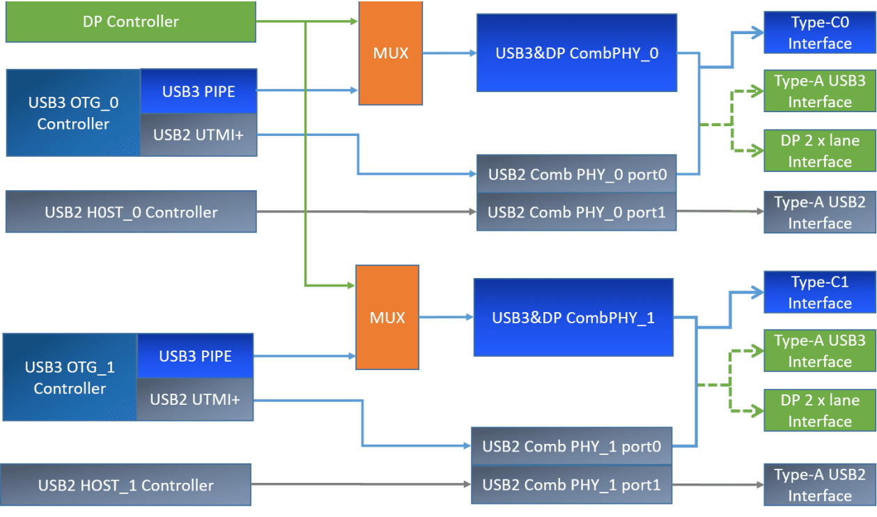
Original technical figure 1, English PDF page 6
Figure 1-1 Schematic diagram of RK3399 USB controller and PHY connections Note:
-
RK3399 can support up to 2 Type-C interfaces, 2 Type-A USB 2.0 interfaces, and 1 USB 2.0 HSIC interface simultaneously;
-
RK3399 only supports 1 DP controller, and the SDK default design connects the DP controller to Type- C0. In actual product applications, it can be switched to Type-C1 by software, but only one can be chosen.
-
The USB 3.1 OTG controller and DP controller share the USB3.1/DP Combo PHY, which can form a fully functional Type-C interface or can be used independently (e.g., common Type-A USB 3.1 interface + DP interface [2 x lanes]);
-
The USB 3.1/DP Combo PHY only supports USB 3.1 Gen1 and is not backward compatible with USB 2.0. Therefore, they are actually combined with the USB 2.0 PHY in chip design to support the complete USB
3.1 protocol function. These two parts of the PHY are independent in the chip’s internal hardware module, and the power supply is also independent. Among them, USB 3.1/DP Combo PHY0 is fixed to combine with USB2 Combo PHY0’s port0, and USB 3.1/DP Combo PHY1 is fixed to combine with USB2 Combo PHY1’s port0. This combination relationship will be reflected in the Linux USB DTS;
- It should be noted that the types of interfaces supported by RK3399 USB are not limited to the Type- C/A USB interface types described in Figure 1-1, but can support all common USB interfaces, including Type-C USB 2.0/3.1, Type-A USB 2.0/3.1, Micro USB 2.0/3.1, etc. For specific information, please refer to RK3399 USB Supported Interface Types. To adapt to different USB circuit designs and interface types, the Linux kernel USB driver has been software compatible, and developers only need to configure the Linux USB DTS correctly according to the product’s USB hardware circuit to enable the corresponding USB interface functions. For detailed USB DTS configuration methods, please refer to RK3399 USB DTS Configuration.
2. RK3399 USB Supported Interface Types
RK3399 USB can support the common USB interface types as shown in Figure 2-1. During product design, the USB hardware circuit can be flexibly designed according to the actual application scenario requirements.
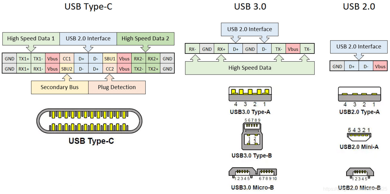
Original technical figure 2, English PDF page 7
Figure 2-1 USB Interface Types Supported by RK3399
2.1 Type-C Interface Types
2.1.1 Type-C USB 3.1 & DP Full-Function Interface
The RK3588 Type-C0/1 supports full-function Type-C interface capabilities, as shown in Figure 2-2 below, with the main features supported as follows: Support for Type-C PD (requires an external Type-C Controller Chip) Support for USB 3.1 Gen1 5Gbps data transfer Support for DP Alternate Mode
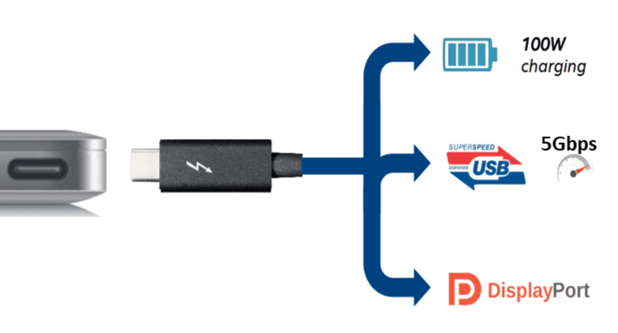
Original technical figure 3, English PDF page 8
Figure 2-2 Type-C USB 3.1/DP Interface The pin definition for the male and female ends of the Type-C interface is shown in Figure 2-3 below.
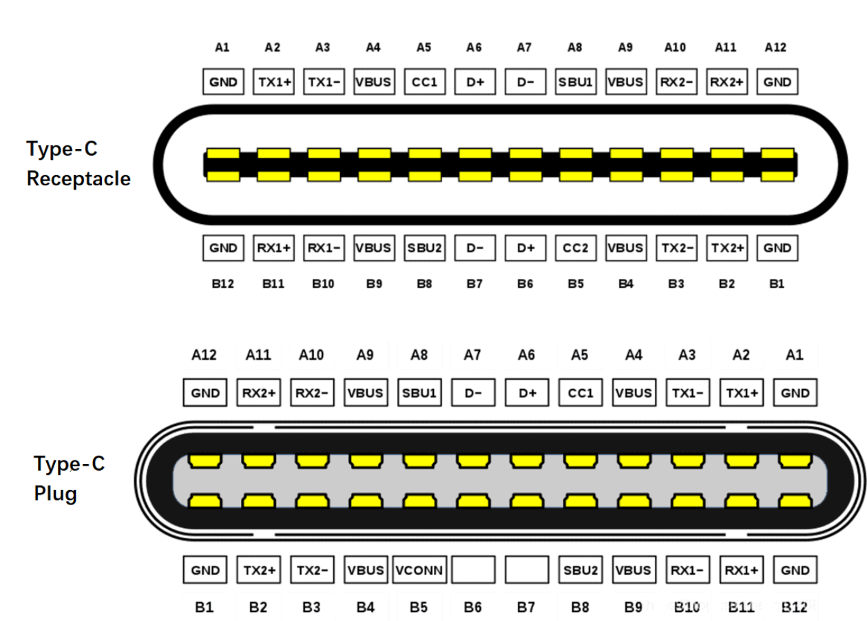
Original technical figure 4, English PDF page 8
Figure 2-3 Pin Definitions for Type-C Interface Table 2-1 Pin Descriptions for Type-C Interface
| Pin | Name | Description | Pin | Name | Description |
|---|---|---|---|---|---|
| A1 | GND | Ground | B12 | GND | Ground |
| A2 | SSTXp1 | SuperSpeed Differential Signal TX1+ |
B11 | SSRXp1 | SuperSpeed Differential Signal RX1+ |
| A3 | SSTXn1 | SuperSpeed Differential Signal TX1- |
B10 | SSRXn1 | SuperSpeed Differential Signal RX1- |
| A4 | VBUS | USB Bus Power | B9 | VBUS | USB Bus Power |
| A5 | CC1 | Configuration Channel | B8 | SBU2 | Sideband Use (SBU) |
| A6 | Dp1 | USB 2.0 Differential Signal D1+ |
B7 | Dn2 | USB 2.0 Differential Signal D2- |
| A7 | Dn1 | USB 2.0 Differential Signal D1- | B6 | Dp2 | USB 2.0 Differential Signal D2+ |
| A8 | SBU1 | Sideband Use (SBU) | B5 | CC2 | Configuration Channel |
| A9 | VBUS | USB Bus Power | B4 | VBUS | USB Bus Power |
| A10 | SSRXn2 | SuperSpeed Differential Signal RX2- |
B3 | SSTXn2 | SuperSpeed Differential Signal TX2- |
| A11 | SSRXp2 | SuperSpeed Differential Signal RX2+ |
B2 | SSTXp2 | SuperSpeed Differential Signal TX2+ |
| A12 | GND | Ground | B1 | GND | Ground |
Table 2-2 Connection Relationship between RK3399 Type-C0 and Type-C Interface
| RK3399 Type-C0 Pin | Type-C Interface Pin |
Relationship Description |
|---|---|---|
| TYPEC0_TX1P/TX1M | A2/A3 | Can be used for USB 3.1 Tx1 or DP Tx lane0 |
| TYPEC0_RX1P/RX1M | B11/B10 | Can be used for USB 3.1 Rx1 or DP Tx lane1 |
| TYPEC0_RX2P/RX2M | A11/A10 | Can be used for USB 3.1 Rx2 or DP Tx lane2 |
| TYPEC0_TX2P/TX2M | B2/B3 | Can be used for USB 3.1 Tx2 or DP Tx lane3 |
| TYPEC0_DP/DM | A6/A7, B6/B7 | Connected to RK3399 TYPEC0_OTG_DP/DM, where A6 and B6 are paralleled, A7 and B7 are paralleled |
| TYPEC0_SBU1/SBU2 | A8/B8 | Connected to the AUX of RK3399 USBDP PHY, used only for DP Alternate Mode |
| TYPEC0_SBU1_DC/SBU2_DC | A8/B8 | Used to control the pull-up during DP AUX transmission (Note: No need to connect to GPIO) |
| TYPEC0_CC1/CC2 | A5/B5 | Connected to the external Type-C controller chip (HUSB311/FUSB302), no need to connect to R3399 SoC’s CC1/CC2 |
| TYPEC0_U2VBUSDET | A4/A9/B4/B9 | Type-C interface VBUS is converted through a voltage conversion circuit to 3V before connecting to RK3399 SoC’s VBUSDET |
Note:
-
The CC1/CC2 of the RK3399 chip is not used; it can be left floating by default during hardware design;
-
The internal USBDP PHY of the RK3399 chip can support the pull-up and pull-down control of TYPEC0_SBU1_DC/SBU2_DC without requiring additional GPIO, which is different from RK3588;
-
The RK3399 chip internally supports only one DP controller, so Type-C0 and Type-C1 cannot support DP functions simultaneously, which is different from RK3588 (RK3588 supports two independent DP controllers);
-
The RK3399 Type-C software driver does not support the constant power supply scheme for TYPEC0_U2VBUSDET, therefore, the hardware circuit design must connect TYPEC0_U2VBUSDET through a voltage conversion circuit to the Type-C interface VBUS to support USB Device mode hot-plugging and BC 1.2 charging detection functions, which is different from RK3588;
-
Both RK3399 and RK3588 support Type-C USB&DP full-function interfaces, but their USBDP PHY lane multiplexing relationships differ, as shown in Table 2-3 below. Table 2-3 USBDP PHY Lane Multiplexing Relationships between RK3399 and RK3588
| USBDP PHY Lane | RK3399 USB | RK3399 DP | RK3588 USB | RK3588 DP |
|---|---|---|---|---|
| lane0 | USB3 Tx1 | DP TX0 | USB3 Rx1 | DP TX0 |
| lane1 | USB3 Rx1 | DP TX1 | USB3 Tx1 | DP TX1 |
| lane2 | USB3 Rx2 | DP TX2 | USB3 Rx2 | DP TX2 |
| lane3 | USB3 Tx2 | DP TX3 | USB3 Tx2 | DP TX3 |
2.1.2 Type-C to Type-A USB & DP Interface
RK3399 Type-C0 can be split into an independent Type-A USB 3.1 interface and a DP interface, for example:
-
Type-A USB 3.1 (using USBDP PHY0’s lane0/1) + DP 1.3 (using USBDP PHY0’s lane2/3);
-
Type-A USB 3.1 (using USBDP PHY0’s lane0/1) + DP to VGA (using USBDP PHY0’s lane2/3). RK3588 Type-C0 can also be split into an independent Type-A USB 2.0 interface and a DP (4 x lanes) interface, for example: Type-A USB 2.0 (not using USBDP PHY) + DP 4 x lane to HDMI2.0 (using USBDP PHY’s lane0/1/2/3). Note:
-
The SDK Linux-4.4/4.19 kernel Type-C driver released by Rockchip does not support the split use of USB and DP by default. For software modifications, please refer to Type-C to Type-A USB & DP DTS Configuration;
-
Considering that RK3399 only supports one DP controller, Type-C0 and Type-C1 cannot support DP functionality simultaneously. Therefore, in hardware design, it is recommended to prioritize Type-C0 supporting USB&DP functionality and Type-C1 supporting USB only, which can reduce the workload of software development.
-
In theory, RK3399 can also support a combination where Type-A USB 3.1 uses lane2/lane3 and DP uses lane0/lane1, but it requires software developers to modify the kernel DTS configuration themselves, which will increase the development workload. Therefore, unless there are special hardware design considerations, it is recommended to prioritize the two conventional combinations provided above.
2.1.3 Type-C USB 2.0 Only Interface
The RK3399 can be simplified to a Type-C USB 2.0 only interface. As shown in Figure 2-4: Supports Type-C PD (requires an external Type-C Controller Chip) Supports USB 2.0 480Mbps data transfer Does not support DP Alternate Mode This design approach is primarily aimed at simplifying the hardware circuit design, but it will reduce the maximum USB transfer rate. At the same time, to accommodate this interface design, significant modifications to the Linux USB DTS are required. Please refer to Type-C USB 2.0 Only DTS Configuration.
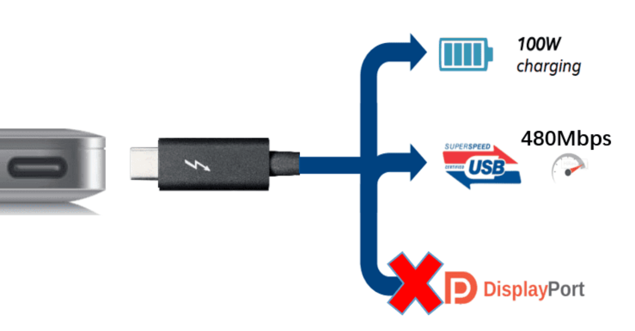
Original technical figure 5, English PDF page 12
Figure 2-4 Type-C USB 2.0 Only Interface
2.2 Type-A Interface Type
2.2.1 Type-A USB 3.1 Interface
The RK3399 can support up to 2 Type-A USB 3.1 interfaces, including: Type-C0 to Type-A USB 3.1 Type-C1 to Type-A USB 3.1
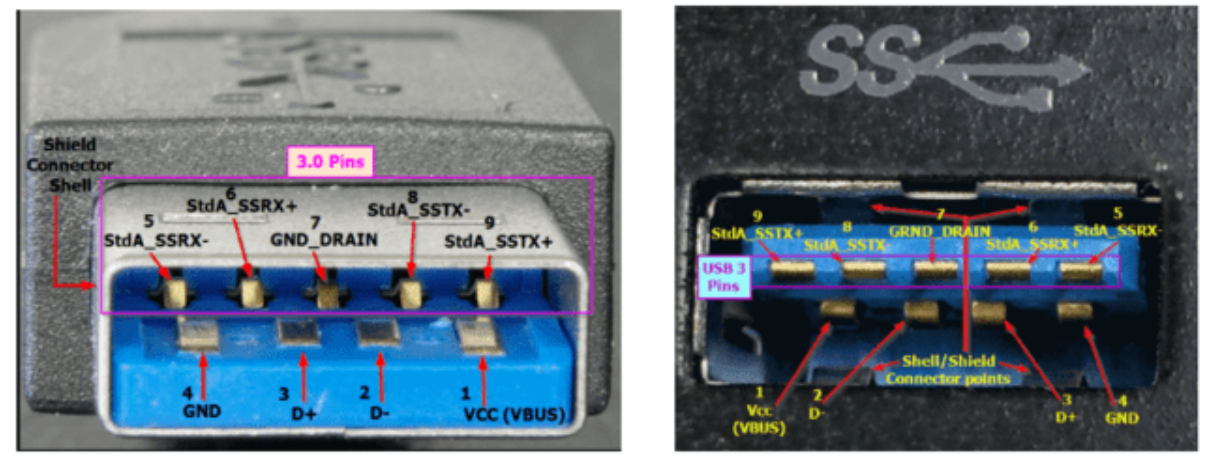
Original technical figure 6, English PDF page 12
Figure 2-5 Type-A USB 3.1 Interface
2.2.2 Type-A USB 2.0 Interface
The RK3399 can support up to 4 Type-A USB 2.0 interfaces, including: Type-C0 to Type-A USB 2.0 Type-C1 to Type-A USB 2.0 USB 2.0 HOST0 USB 2.0 HOST1
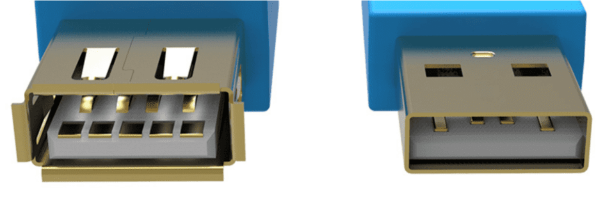
Original technical figure 7, English PDF page 13
Figure 2-6 Type-A USB 2.0 Interface
2.3 Micro Interface Types
2.3.1 Micro USB 3.1 Interface
The RK3399 Type-C0/1 can support the interface design of Micro USB 3.1. However, considering the larger PCB area occupied by the Micro USB 3.1 interface, it is currently less commonly used in products. The pin difference between Micro USB 3.1 and Type-A USB 3.1 is mainly the addition of the OTG ID pin, which is used for hardware automatic detection of ID voltage levels and switching software automatic switching of OTG Device/HOST mode. The OTG ID pin needs to be connected to the RK3399 TYPEC0_ID pin (Type_C1 corresponds to TYPEC1_ID), and the ID is internally pulled up to a high voltage level of 1.8V in the chip, so there is no need for external circuit pull-up.
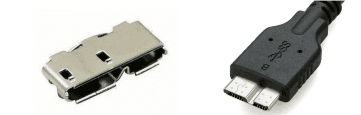
Original technical figure 8, English PDF page 13
Figure 2-7 Micro USB 3.1 Interface
2.3.2 Micro USB 2.0 Interface
The RK3399 Type-C0 can support the interface design of Micro USB 2.0. This design approach is primarily aimed at simplifying the hardware circuit design, but it will reduce the maximum USB transfer rate. The pin difference between Micro USB 2.0 and Type-A USB 2.0 is mainly the addition of the OTG ID pin, which is used for hardware automatic detection of ID voltage levels and switching between OTG Device/HOST mode. The OTG ID pin needs to be connected to the RK3399 TYPEC0_ID pin. The ID is already pulled up to a high voltage level of 1.8V internally within the chip, so there is no need for external circuit pull-up.
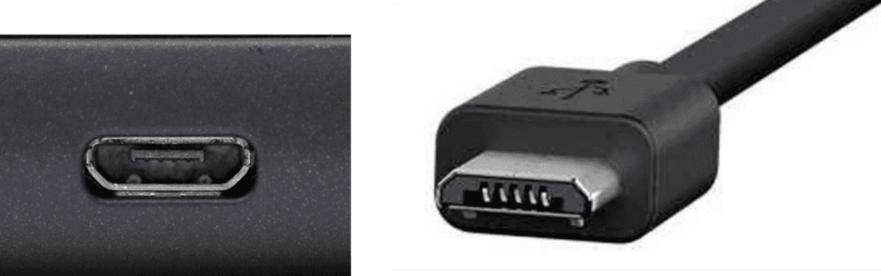
Original technical figure 9, English PDF page 14
Figure 2-8 Micro USB 2.0 Interface
3. RK3399 Type-C USB Usage Notes
-
RK3399 Type-C USB 3.1 Splitting into USB 2.0 Port and USB 3.1 Port Usage Notes Characteristics of the RK3399 USB 3.1 controller include: (1) Device and Host functions do not support simultaneous use; (2) In Host mode, the USB 2.0 Host Port and USB 3.1 Host Port can be used independently and simultaneously; (3) In Device mode, USB 2.0 Device and USB 3.1 Device cannot work simultaneously. Based on the above design features of the USB 3.1 controller, in product applications, if it is clear that after splitting USB 3.1, there are only Host application requirements and no Device application requirements, it is suitable to split and use. Otherwise, it is recommended not to split the USB 2.0 port and USB 3.1 port of USB 3.1 to avoid restrictions on Device functionality.
-
RK3399 Type-C USB 3.1 & DP Splitting into Independent Interface Usage Notes The RK3399 Type-C can be split into an independent Type-A USB 3.1 interface and a DP interface, with the main application scenarios including: USB 3.1 + DP 2 x lanes and USB 2.0 + DP 4 x lanes. The SDK software solution released by the Rockchip platform does not fully support the way of splitting USB & DP usage. For specific usage notes, please refer to the section Type-C to Type-A USB&DP DTS Configuration.
-
RK3399 TYPEC0_U2VBUSDET Hardware Design Notes TYPEC0_U2VBUSDET is used for USB Device scenarios to detect the connection and disconnection of USB Devices. The design notes for TYPEC0_USB20_VBUSDET are as follows: (1) To support the RK3399 Maskrom USB firmware download function, it is necessary to ensure that TYPEC0_U2VBUSDET is externally pulled high by default when the system is powered up, and cannot be left floating; (2) The high voltage range of the RK3399 chip input end TYPEC0_U2VBUSDET is [1.4V ~ 3.3V]; (3) Software (including: Linux-4.4/4.19/5.10) does not yet support the Type-C interface solution where TYPEC0_U2VBUSDET is constantly powered (fixed pull-up). Therefore, it is required that in hardware design, a voltage conversion circuit is used to connect TYPEC0_U2VBUSDET to the VBUS pin of the Type- C interface. If TYPEC0_U2VBUSDET is constantly powered, it will cause abnormalities in the hot- plugging function of the USB Device and BC 1.2 charging detection.
-
RK3399 Dual Type-C Interface Usage Notes Both RK3399 Type-C0/1 USB controllers support USB 3.1 OTG functionality and are backward compatible with USB 2.0/1.1/1.0. However, due to the limitations of the kernel’s USB Gadget framework, only one USB controller is supported as Device functionality, so the SDK defaults to Type-C0 supporting OTG mode, while Type-C1 only supports Host mode. In practical applications: (1) Firmware download only supports the use of the Type-C0 interface and cannot be changed; (2) ADB defaults to using Type-C0. If you want to change to using Type-C1, please refer to the section Method to Support OTG mode for Type-C1; (3) In theory, dual Type-C USB OTG functionality can be supported. However, the Rockchip platform has not yet supported a software solution for dynamically switching Device mode between OTG0/1. Therefore, it is recommended to fix the use of Type-C0 or Type-C1 as Device mode in products. If a product must support a dual Type-C OTG scheme, developers need to implement this functionality. The general idea is: the application layer obtains the kernel Type-C0/C1 USB mode in real-time, and then dynamically configures the kernel nodes based on the USB mode: /config/usb_gadget/g1/UDC (the function is to bind the USB Gadget driver and the corresponding Type-C USB controller driver).
4. RK3399 USB DTS Configuration
RK3399 USB DTS Configuration encompasses both chip-level USB controller/PHY DTSI configuration and board-level DTS configuration. The chip-level configuration primarily manages the common resources and attributes of the USB controller and PHY, including: reg, clock, reset, grf, interrupts, and controller-specific attributes. The board-level configuration mainly configures VBUS control, Type-C controller chips (such as: FUSB302), and special attributes related to the hardware circuitry.
4.1 USB Chip-Level DTSI Configuration
The main nodes related to the USB controller and PHY in the RK3399 DTSI file are shown in the table below, as the USB DTSI node configuration pertains to the common resources and attributes of the USB controller and PHY, developers are advised not to modify them. Table 4-1 Correspondence between RK3399 USB Interfaces and USB DTS Nodes
| USB Interface Name (Schematic) | USB Controller DTS Node | USB PHY DTS Node |
|---|---|---|
| TYPEC0 | usbdrd3_0 usbdrd_dwc3_0 |
u2phy0_otg tcphy0_usb3 |
| TYPEC1 | usbdrd3_1 usbdrd_dwc3_1 |
u2phy1_otg tcphy1_usb3 |
| USB20_HOST0 | usb_host0_ehci usb_host0_ohci |
u2phy0_host |
| USB20_HOST1 | usb_host1_ehci usb_host1_ohci |
u2phy1_host |
USB Controller DTSI Nodes are as follows (using Linux-4.19 kernel as an example) arch/arm64/boot/dts/rockchip/rk3399.dtsi
/* USB3.1 OTG0 DWC3 Controller, support USB3.1/2.0/1.1/1.0 */
usbdrd3_0: usb@fe800000 {
        compatible = "rockchip,rk3399-dwc3";
        ......
        usbdrd_dwc3_0: usb@fe800000 {
                compatible = "snps,dwc3";
                ......
                dr_mode = "otg"; /* Type-C0 defaults to OTG mode */
                phys = <&u2phy0_otg>, <&tcphy0_usb3>;  /* Configure USB2.0 and USB3.1 PHY
properties */
                phy-names = "usb2-phy", "usb3-phy";
                ......
        };
};

/* USB3.1 OTG1 DWC3 Controller, support USB3.1/2.0/1.1/1.0 */
usbdrd3_1: usb@fe900000 {
        compatible = "rockchip,rk3399-dwc3";
        ......
        usbdrd_dwc3_1: usb@fe900000 {
                compatible = "snps,dwc3";
                ......
                dr_mode = "host"; /* Type-C1 defaults to Host mode */
                phys = <&u2phy1_otg>, <&tcphy1_usb3>; /* Configure USB2.0 and USB3.1 PHY
properties */
                phy-names = "usb2-phy", "usb3-phy";
                ......
        };
};

/* USB2.0 HOST0 EHCI Controller, support USB2.0 only */
usb_host0_ehci: usb@fe380000 {
        compatible = "generic-ehci";
        ......
        phys = <&u2phy0_host>;
        ......
};

/* USB2.0 Host0 OHCI Controller, support USB1.1/1.0*/
usb_host0_ohci: usb@fe3a0000 {
        compatible = "generic-ohci";
        ......
        phys = <&u2phy0_host>;
        ......
};

/* USB2.0 HOST1 EHCI Controller, support USB2.0 only */
usb_host1_ehci: usb@fe3c0000 {
        compatible = "generic-ehci";
        ......
        phys = <&u2phy1_host>;
        ......
};

/* USB2.0 HOST1 OHCI Controller, support USB1.1/1.0 */
usb_host1_ohci: usb@fe3e0000 {
        compatible = "generic-ohci";
        ......
        phys = <&u2phy1_host>;
        ....
};
USB PHY DTSI Nodes are as follows (using Linux-4.19 kernel as an example) arch/arm64/boot/dts/rockchip/rk3399.dtsi
/* USB2.0 Combo PHY0/1 */
grf: syscon@ff770000 {
        compatible = "rockchip,rk3399-grf", "syscon", "simple-mfd";
        ......
        u2phy0: usb2-phy@e450 {
                compatible = "rockchip,rk3399-usb2phy";
                ......
                u2phy0_host: host-port { /* For USB2.0 HOST0 */
                        #phy-cells = <0>;
                        ......
                };

                u2phy0_otg: otg-port { /* For Type-C0 OTG's USB2 port */
                        #phy-cells = <0>;
                        ......
                };
        };

        u2phy1: usb2-phy@e460 {
                compatible = "rockchip,rk3399-usb2phy";
                ......
                u2phy1_host: host-port { /* For USB2.0 HOST1 */
                        #phy-cells = <0>;
                        ......
                };

                u2phy1_otg: otg-port { /* For Type-C1 OTG's USB2 port */
                        #phy-cells = <0>;
                        ......
                };
        };
};

/* USB3.1/DP Combo PHY0 */
tcphy0: phy@ff7c0000 {
        compatible = "rockchip,rk3399-typec-phy";
        ......
        tcphy0_dp: dp-port { /* For Type-C0's Display function */
                #phy-cells = <0>;
        };

        tcphy0_usb3: usb3-port { /* For Type-C0's USB3.1 function */
                #phy-cells = <0>;
        };
};

/* USB3.1/DP Combo PHY1 */
tcphy1: phy@ff800000 {
        compatible = "rockchip,rk3399-typec-phy";
        ......
        tcphy1_dp: dp-port {  /* For Type-C1's Display function */
                #phy-cells = <0>;
        };

        tcphy1_usb3: usb3-port { /* For Type-C1's USB3.1 function */
                #phy-cells = <0>;
        };
};
Note:
-
USB PHYs and USB controllers have a one-to-one correspondence and need to be configured in pairs. For the internal connection relationship between USB PHYs and controllers on the chip, please refer to RK3399 USB Controller and PHY Introduction. In the DTSI nodes, the corresponding USB PHY is associated with the “phys” property of the USB controller node;
-
Starting from Linux-4.19, the USB DWC3 controller driver has undergone significant upgrades, so the chip-level configuration of the DWC3 controller varies with different kernel versions, mainly reflected in: In the Linux-4.4 kernel rk3399.dtsi, the “power-domains” attribute and “resets” attribute of DWC3 are placed in the parent node of the DWC3 controller usbdrd3_x, while in Linux-4.19 and newer kernel versions, these two attributes are moved to the child node of the DWC3 controller usbdrd_dwc3_x (for most USB application developers, this change can be ignored);
-
The SDK released by the Rockchip platform defaults to using Type-C0 as OTG mode, supporting dynamic switching between Device/Host modes, while Type-C1 is restricted to Host mode. If your product requires using Type-C1 as OTG mode, such as needing to support Type-C1 USB Device ADB functionality, please refer to the sections RK3399 Type-C USB Usage Notes and Method for Supporting OTG Mode on Type-C1 for a detailed understanding of usage restrictions and software modification methods.
4.2 Type-C USB 3.1/DP Full-Function DTS Configuration
Type-C USB 3.1/DP full-function interfaces require cooperation with an external Type-C Controller Chip to achieve functions such as orientation detection, PD (Power Delivery), USB role switching, and DP Alternate Mode. To support different Type-C controller chips, the relevant DTS nodes of the Type-C controller chip must be correctly configured. The early SDK Linux-4.4/Linux-4.19 does not support the standard TCPM software framework and TCPCI protocol, so it can only support FUSB302. The latest Linux-4.19 and above kernel versions have already supported the standard TCPM software framework and TCPCI protocol, thus they can support more Type-C controller chips designed based on the TCPCI standard (such as: HUSB311). Different kernel versions have different DTS configuration methods for Type-C controller chips. Below are the DTS configuration methods for the main Type-C controller chips adapted on the Rockchip platform, FUSB302 and HUSB311, in different Linux kernel versions.
4.2.1 Linux-4.4 Type-C USB 3.1 & DP Full-Feature DTS Configuration [FUSB302]
Taking the Type-C0 interface of RK3399 IND EVB as an example: arch/arm64/boot/dts/rockchip/rk3399-evb-ind.dtsi
&i2c4 {
        fusb0: fusb30x@22 { /* Configure FUSB302 chip hardware information */
                compatible = "fairchild,fusb302";
                reg = <0x22>;
                pinctrl-names = "default";
                pinctrl-0 = <&fusb0_int>;
                int-n-gpios = <&gpio1 2 GPIO_ACTIVE_HIGH>;
                vbus-5v-gpios = <&gpio1 18 GPIO_ACTIVE_HIGH>;
                status = "okay";
        };
};

&tcphy0 { /* Enable Type-C0 USB3.1 PHY */
        extcon = <&fusb0>; /* Configure extcon property for receiving Type-C notifier from
FUSB302 driver */
        status = "okay";
};

&u2phy0 { /* Enable Type-C0 USB2.0 PHY */
        status = "okay";
        extcon = <&fusb0>; /* Configure extcon property for receiving Type-C DRD notifier
from FUSB302 driver */
        u2phy0_otg: otg-port {
                status = "okay";
        };
};

&usbdrd3_0 { /* Enable USB3 controller parent node */
        status = "okay";
        extcon = <&fusb0>; /* Configure extcon property for receiving Type-C DRD notifier
from FUSB302 driver */
};

&usbdrd_dwc3_0 { /* Enable USB3 controller child node */
        status = "okay";
};

&pinctrl {
    fusb30x { /* Configure interrupt and vbus gpio pinctrl for FUSB302 driver */
                fusb0_int: fusb0-int {
                        rockchip,pins = <1 2 RK_FUNC_GPIO &pcfg_pull_up>,
                                        <1 18 RK_FUNC_GPIO &pcfg_pull_up>;
                };
        };
};
4.2.2 Linux-4.19 Type-C USB 3.1 & DP Full-Function DTS Configuration[FUSB302]
The Linux-4.19 DTS configuration for Type-C [FUSB302] is essentially the same as Linux-4.4, with the only difference being the location of the “extcon” attribute reference for the DWC3 controller node.
&usbdrd3_0 {
        status = "okay";
};

&usbdrd_dwc3_0 {
        status = "okay";
        extcon = <&fusb0>; /* In Linux-4.19, the extcon attribute is placed within the DWC3
sub-node */
};
4.2.3 Linux-4.19 Type-C USB 3.1&DP Full-Function DTS Configuration[HUSB311]
The latest Linux-4.19 kernel can support both HUSB311 and ET7303, two Type-C controller chips. Considering that both HUSB311 and ET7303 have the same I2C device address of 4E, the DTS configurations are essentially the same, with only the node name and the “compatible” attribute needing to be modified. Therefore, this section will use HUSB311 as an example for explanation. Hardware Design Recommendations: The FUSB302 on the RK3399 EVB IND can be directly replaced with HUSB311. Software Modification Notes: Both HUSB311 and ET7303 chips are based on the kernel Type-C driver TCPM framework, thus requiring Linux-4.19 to be synchronized with the latest code from develop-4.19. If it is not possible to synchronize the complete kernel code, at least the following directories should be synchronized:
kernel/include/linux/usb
kernel/drivers/usb/typec
kernel/drivers/usb/dwc3
Additionally, the following patches need to be manually updated:
0001-usb-typec-tcpm-add-vdm-retry-mechanism.patch
0002-arm64-dts-rockchip-rk3399-ind-support-type-c-port-co.patch
0003-arm64-rockchip_defconfig-enable-tcpm-and-husb311-and.patch
Please download the complete reference materials: “RK3399_Linux-4.19_TypeC-HUSB311-ET7303-Reference Design” for modification. Download link: https://redmine.rockchip.com.cn/documents/113 Taking the Type-C0 adaptation of HUSB311 on the RK3399 IND EVB as an example: arch/arm64/boot/dts/rockchip/rk3399-evb-ind.dtsi
/* Include header files */
#include "dt-bindings/usb/pd.h"

/* Optional configuration for hardware schemes where vbus is controlled by gpio */
vcc_otg_vbus: otg-vbus-regulator {
        compatible = "regulator-fixed";
        gpio = <&gpio1 RK_PC2 GPIO_ACTIVE_HIGH>;
        pinctrl-names = "default";
        pinctrl-0 = <&otg_vbus_drv>;
        regulator-name = "vcc_otg_vbus";
        regulator-min-microvolt = <5000000>;
        regulator-max-microvolt = <5000000>;
        enable-active-high;
};

&i2c4 {
        /* For et7303, modify to usbc0: et7303@4e */
        usbc0: husb311@4e {
                /* For et7303, compatible = "etek,et7303" */
                compatible = "hynetek,husb311";
                reg = <0x4e>;
                /* Interrupt gpio configuration, please modify according to the schematic
design */
                interrupt-parent = <&gpio1>;
                interrupts = <2 IRQ_TYPE_LEVEL_LOW>;
                pinctrl-names = "default";
                pinctrl-0 = <&husb311_int>;
                /*
                 * Vbus configuration
                 * If vbus is controlled by gpio, then vbus-supply = <&vcc_otg_vbus>
configuration is needed;
                 * If vbus is output by RK817/RK818/bq25700/other charge ic, then no vbus-
supply = <&vcc_otg_vbus> configuration is needed;
                 */
                vbus-supply = <&vcc_otg_vbus>;
                status = "okay";

                usb_con: connector {
                        data-role = "dual";
                        power-role = "dual";
                        try-power-role = "sink";
                        /*
                         * source-pdos: PDO_FIXED(voltage(mV), current(mA),
PDO_FIXED_USB_COMM)
                         * When the motherboard acts as Source, the list of voltage/current
that the motherboard vbus can output, for RK platforms, use default values
                         */
                        source-pdos = <PDO_FIXED(5000, 2000, PDO_FIXED_USB_COMM)>;
                        /*
                         * sink-pdos: <PDO_FIXED(voltage(mV), current(mA),
PDO_FIXED_USB_COMM)>
                         * When the motherboard acts as Sink, the list of voltage/current
that the motherboard can support.
                         * If there is a PD fast-charging requirement, sink-pdos
configuration depends on the maximum voltage/current of the charger ic input and the
motherboard's capacity
                         * If the voltage is too high, it may burn the motherboard, please
communicate with the hardware engineer for this detail.
                         * Below is the configuration for the maximum charging
voltage(20v)/current(3A) supported by the motherboard, please modify appropriately according
to the hardware design and actual requirements.
                         * For example, if the motherboard only supports a maximum charging
voltage(12v)/current(3A), 15v/3A and 20V/3A must be removed.
                         */
                        sink-pdos = <PDO_FIXED(5000, 3000, PDO_FIXED_USB_COMM)
                                     PDO_FIXED(9000, 3000, PDO_FIXED_USB_COMM)
                                     PDO_FIXED(12000, 3000, PDO_FIXED_USB_COMM)
                                     PDO_FIXED(15000, 3000, PDO_FIXED_USB_COMM)
                                     PDO_FIXED(20000, 3000, PDO_FIXED_USB_COMM)>;
                         /* If there is no PD fast-charging requirement, sink-pdos
configuration can be as follows. */
                        sink-pdos = <PDO_FIXED(5000, 2000, PDO_FIXED_USB_COMM)>;
                        /* Charging power(op-sink-microwatt) = max_vol(mV) * max_cur(mA),
use default */
                        op-sink-microwatt = <10000000>;

                        /* RK3399 platform needs to configure dp altmodes, default
configuration is okay */
                        altmodes {
                                #address-cells = <1>;
                                #size-cells = <0>;

                                altmode@0 {
                                        reg = <0>;
                                        svid = <0xff01>;
                                        vdo = <0xffffffff>;
                                };
                        };
                };
        };
};

&pinctrl {
        husb311 {
                husb311_int: husb311-int {
                        rockchip,pins = <1 RK_PA2 RK_FUNC_GPIO &pcfg_pull_up>;
                };
        };

        usb {
                otg_vbus_drv: otg-vbus-drv {
                        /* Optional, if there is no vcc_otg_vbus, this configuration is not
needed */
                        rockchip,pins = <1 RK_PC2 RK_FUNC_GPIO &pcfg_pull_none>;
                };
        };
};

&cdn_dp {
        status = "okay";
        extcon = <&husb0>;
        phys = <&tcphy0_dp>;
};

bq25700: bq25700@6b {
        compatible = "ti,bq25703";
        reg = <0x6b>;
        extcon = <&husb0>;
        ......
};

&tcphy0 {
        extcon = <&husb0>;
        status = "okay";
};
&u2phy0 {
        status = "okay";
        extcon = <&husb0>;
};

&usbdrd_dwc3_0 {
        status = "okay";
        extcon = <&husb0>;
};
USB VBUS Controlled by RK817/RK818/bq25700 and Other PMICs DTS Configuration Instructions
/* rk818 */
rk818: pmic@1c {
        extcon = <&usbc0>;
};

/* rk817 */
rk817: pmic@20 {
        charger {
                extcon = <&usbc0>;
        };
};

/* bq25700 */
bq25700: bq25700@09 {
        extcon = <&usbc0>;
};
4.2.4 Linux-5.10 Type-C USB 3.1 & DP Full-Function DTS Configuration [FUSB302]
The Linux-5.10 Type-C driver utilizes the standard TCPM framework, which differs significantly from the Linux-
4.19 and earlier kernel versions. The Linux-5.10 Type-C driver employs the remote-endpoint and registration callback mechanism, replacing the previous extcon mechanism. Consequently, in the DTS configuration related to Linux-5.10 Type-C, the “extcon” property is no longer required. It should also be noted that the DP functionality of the Type-C interface in Linux-5.10 RK3399 is not yet complete. Therefore, the dp_altmode node configuration has not been added in the tcphy0 node and usb_con node of Linux-5.10. Taking the Type-C0 interface of the RK3399 IND EVB as an example: arch/arm64/boot/dts/rockchip/rk3399-evb-ind.dtsi
/* Configure VBUS gpio regulator for Type-C USB Host mode VBUS 5V output control */
vbus_typec: vbus-typec-regulator {
        compatible = "regulator-fixed";
        enable-active-high;
        gpio = <&gpio1 18 GPIO_ACTIVE_HIGH>;
        pinctrl-names = "default";
        pinctrl-0 = <&vcc5v0_typec0_en>;
        regulator-name = "vbus_typec";
        vin-supply = <&vcc5v0_sys>;
};

/* Configure FUSB302 chip hardware information */
&i2c4 {
        usbc0: fusb302@22 {
                compatible = "fcs,fusb302";
                reg = <0x22>;
                interrupt-parent = <&gpio1>;
                interrupts = <RK_PA2 IRQ_TYPE_LEVEL_LOW>;
                pinctrl-names = "default";
                pinctrl-0 = <&usbc0_int>;
                vbus-supply = <&vbus_typec>;
                status = "okay";

                ports {
                        #address-cells = <1>;
                        #size-cells = <0>;
                        /* Used to associate USB controller for USB role switching
functionality */
                        port@0 {
                                reg = <0>;
                                usbc0_role_sw: endpoint@0 {
                                        remote-endpoint = <&dwc3_0_role_switch>;
                                };
                        };
                };

                usb_con: connector { /* Used to describe PD protocol related information */
                        compatible = "usb-c-connector";
                        label = "USB-C";
                        data-role = "dual";
                        power-role = "dual";
                        try-power-role = "sink";
                        op-sink-microwatt = <1000000>;
                        sink-pdos =
                                <PDO_FIXED(5000, 2500, PDO_FIXED_USB_COMM)>;
                        source-pdos =
                                <PDO_FIXED(5000, 1500, PDO_FIXED_USB_COMM)>;

                        ports {
                                #address-cells = <1>;
                                #size-cells = <0>;
                                /* Used to associate Type-C PHY for orientation switching
functionality */
                                port@0 {
                                        reg = <0>;
                                        usbc0_orien_sw: endpoint {
                                                remote-endpoint =
<&tcphy0_orientation_switch>;
                                        };
                                };
                                /* TODO Associate Type-C PHY for dp_altmode functionality */
                        };
                };
        };
};

/* Enable Type-C0 USB3.1 PHY */
&tcphy0 {
        status = "okay";
        orientation-switch; /* Used to enable Type-C PHY driver to register orientation
switch callback function */
        port {
                #address-cells = <1>;
                #size-cells = <0>;
                tcphy0_orientation_switch: endpoint@0 {
                        reg = <0>;
                        remote-endpoint = <&usbc0_orien_sw>; /* Associate FUSB302 for
orientation switching functionality */
                };
        };
};

/* Enable Type-C0 USB2.0 PHY */
&u2phy0 {
        status = "okay";

        u2phy0_otg: otg-port {
                status = "okay";
        };
};

/* Enable USB3 controller parent node */
&usbdrd3_0 {
        status = "okay";
};

/* Enable USB3 controller child node */
&usbdrd_dwc3_0 {
        status = "okay";
        usb-role-switch; /* Used to enable DWC3 driver to register USB Role Switch callback
function */
        port {
                #address-cells = <1>;
                #size-cells = <0>;
                dwc3_0_role_switch: endpoint@0 {
                        reg = <0>;
                        remote-endpoint = <&usbc0_role_sw>; /* Associate FUSB302 for USB
role switching functionality */
                };
        };
};
&pinctrl {
        usb-typec {
                usbc0_int: usbc0-int { /* Configure FUSB302 driver interrupt gpio pinctrl */
                        rockchip,pins = <1 RK_PA2 RK_FUNC_GPIO &pcfg_pull_up>;
                };

                vcc5v0_typec0_en: vcc5v0-typec0-en { /* Configure FUSB302 driver VBUS gpio
pinctrl */
                        rockchip,pins =
                                <1 RK_PC2 RK_FUNC_GPIO &pcfg_pull_none>;
                };
        };
};
4.2.5 Linux-5.10 Type-C USB 3.1 & DP Full-Function DTS Configuration[HUSB311]
Replace the FUSB302 chip with the HUSB311 chip by making simple modifications based on the Linux-5.10 Type-C USB 3.1 & DP Full-Function DTS Configuration[FUSB302]. Refer to the modifications:
// Configure the external Type-C controller chip HUSB311
&i2c2 {
        usbc0: husb311@4e {
                compatible = "hynetek,husb311";
                reg = <0x4e>;
                ......
        };
};
4.3 USB & DP DTS Configuration for Type-C to Type-A
The hardware design solution for Type-C to Type-A USB & DP has the following features: Type-C is split into two independent interfaces: USB and DP; Supports USB 3.1 + DP 2 x lanes; Supports USB 2.0 + DP 4 x lanes; This can be further detailed into two different implementation schemes, which are:
-
USB 3.1 & DP DTS Configuration for Type-C to Type-A
-
USB 2.0 & DP DTS Configuration for Type-C to Type-A Note: The RK3399 SDK Linux-4.4/4.19 kernel released by Rockchip does not support the default method of splitting USB and DP usage, and requires manual addition of a special driver drivers/extcon/extcon-pd- virtual.c . The role of this driver is to replace the Type-C controller chip driver, sending notifications to the Type-C PHY driver, DP controller driver, and USB controller driver. If you have this feature requirement, please submit the requirement to Rockchip’s Redmine platform.
The RK3399 SDK Linux-5.10 kernel released by Rockchip does not yet support the splitting of USB and DP usage, and it is planned to no longer adopt the method of adding special drivers. The feature is under development. The download address for the reference design of RK3399 TypeC to USB2.0 + DP 4xlanes hardware and software: https://redmine.rockchip.com.cn/documents/113
4.3.1 USB 3.1 & DP DTS Configuration for Type-C to Type-A
This solution supports Type-A USB 3.1 (using lane0/1 of Type-C PHY) + DP 1.3 (using lane2/3 of Type-C PHY). Linux-4.4/4.19 DTS reference configuration for Type-C0 to Type-A USB 3.1 & DP DTS:
/* Configure virtual pd driver to send notifications to Type-C PHY driver and DP driver */
vpd0:virtual-pd0{
        compatible = "linux,extcon-pd-virtual";
        pinctrl-names = "default";
        pinctrl-0 = <&vpd0_int>;
        dp-det-gpios = <&gpio4 25 GPIO_ACTIVE_LOW>; /* Configure DP hot-plug detection GPIO
*/
        hdmi-5v-gpios = <&gpio4 29 GPIO_ACTIVE_LOW>; /* Configure HDMI 5V control GPIO */

        /* 0: positive, 1: negative*/
        vpd,init-flip = <0>;
        /* 0: u2, 1: u3*/
        vpd,init-ss = <1>;
        /* 0: dfp, 1: ufp, 2: dp, 3: dp&ufp */
        vpd,init-mode = <3>;
        status = "okay";
};

&pinctrl {
        vpd {
                vpd0_int: vpd0-int { /* Configure GPIO pinctrl */
                        rockchip,pins =
                                <4 25 RK_FUNC_GPIO &pcfg_pull_up>;
                };
        };
};

/* Enable DP controller */
&cdn_dp {
        status = "okay";
        extcon = <&vpd0>; /* Configure extcon property to receive notifications from virtual
PD driver */
        dp_vop_sel = <1>;
};

/* Enable Type-C0 PHY */
&tcphy0 {
        extcon = <&vpd0>; /* Configure extcon property to receive notifications from virtual
PD driver */
        status = "okay";
};

/* Enable USB2 PHY */
&u2phy0 {
        status = "okay";
        /* No need to configure extcon property here */

        u2phy0_otg: otg-port {
                status = "okay";
        };
};

/* Enable USB controller parent node */
&usbdrd3_0 {
        extcon = <&u2phy0>;  /* extcon is optional, only used for Linux-4.4 and Micro
interface. If using Type-A interface, no need to configure, see Note1 */
        status = "okay";
};

/* Enable USB controller child node */
&usbdrd_dwc3_0 {
        dr_mode = "otg"; /* Configure as otg mode */
        phys = <&u2phy0_otg>, <&tcphy0_usb3>; /* Must configure U2 and U3 PHY */
        phy-names = "usb2-phy", "usb3-phy";
        extcon = <&u2phy0>;  /* extcon is only used for Linux-4.19 */
        status = "okay";
};
4.3.2 Type-C to Type-A USB 2.0 & DP DTS Configuration
This solution supports Type-A USB 2.0 (without using Type-C PHY) + DP 4 lanes to HDMI2.0 (using Type-C PHY’s lane0/1/2/3). Linux-4.4/4.19 Type-C0 to Type-A USB 2.0 & DP DTS Reference Configuration:
/* Configure a virtual pd driver to send notifications to the Type-C PHY driver and DP
driver */
vpd0:virtual-pd0{
        compatible = "linux,extcon-pd-virtual";
        pinctrl-names = "default";
        pinctrl-0 = <&vpd0_int>;
        dp-det-gpios = <&gpio4 25 GPIO_ACTIVE_LOW>; /* Configure DP hot-plug detection GPIO
*/
        hdmi-5v-gpios = <&gpio4 28 GPIO_ACTIVE_LOW>; /* Configure HDMI 5V control GPIO */

        /* 0: positive, 1: negative*/
        vpd,init-flip = <0>;
        /* 0: u2, 1: u3*/
        vpd,init-ss = <0>;
        /* 0: dfp, 1: ufp, 2: dp, 3: dp&ufp */
        vpd,init-mode = <2>;
        status = "okay";
};

&pinctrl {
        vpd {
                vpd0_int: vpd0-int { /* Configure GPIO pinctrl */
                        rockchip,pins =
                                <4 25 RK_FUNC_GPIO &pcfg_pull_up>;
                };
        };
};

/* Enable DP controller */
&cdn_dp {
        status = "okay";
        extcon = <&vpd0>; /* Configure extcon property for receiving notifications from the
virtual PD driver */
        dp_vop_sel = <1>;
};

/* Enable Type-C0 PHY */
&tcphy0 {
        extcon = <&vpd0>; /* Configure extcon property for receiving notifications from the
virtual PD driver */
        status = "okay";
};

/* Enable USB2 PHY */
&u2phy0 {
        status = "okay";
        /* No need to configure extcon property here */

        u2phy0_otg: otg-port {
                status = "okay";
        };
};

/* Enable USB controller parent node */
&usbdrd3_0 {
        extcon = <&u2phy0>;  /* extcon is optional, only used for Linux-4.4 and Micro
interface. If using Type-A interface, no configuration is needed, see Note1 */
        status = "okay";
};

/* Enable USB controller child node */
&usbdrd_dwc3_0 {
        dr_mode = "otg"; /* Configure as otg mode */
        maximum-speed = "high-speed"; /* Configure to support high-speed */
        phys = <&u2phy0_otg>, <&tcphy0_usb3>; /* Must configure U2 and U3 PHY */
        phy-names = "usb2-phy", "usb3-phy";
        extcon = <&u2phy0>;  /* extcon is only used for Linux-4.19 */
        status = "okay";
};
Note1: If using a Type-A interface, after the system boots, the application layer needs to configure the USB controller to work in Peripheral mode or Host mode through the OTG mode switch node provided by the kernel. For configuration methods, refer to RK3399 USB OTG Mode Switch Command.
4.4 USB-only DTS Configuration for Type-C to Type-A
The hardware design scheme for USB-only Type-C to Type-A has the following characteristics: Supports only USB3.1/2.0 functionality, does not support DP functionality; Does not support automatic switching to OTG mode, but supports software-forced switching to OTG mode; No need for an external Type-C controller chip; Specifically, it can be detailed into four different implementation schemes, which are:
-
USB 3.1 OTG DTS Configuration for Type-C to Type-A
-
USB 3.1 Host-only DTS Configuration for Type-C to Type-A
-
USB 2.0 OTG DTS Configuration for Type-C to Type-A
-
USB 2.0 Host-only DTS Configuration for Type-C to Type-A
4.4.1 Type-C to Type-A USB 3.1 OTG DTS Configuration
The Type-C to Type-A USB 3.1 OTG solution is typically applied to the Type-C0 USB on the RK3399 platform, supporting Type-A USB 3.1 OTG functionality but not DP functionality. After the system boots, the USB controller defaults to OTG mode or Device mode and cannot automatically switch between Device/Host modes. If the design requires the USB to default to Host functionality after boot, the application layer must actively set the USB controller to work in Host mode through the interface provided by the kernel. For methods to switch OTG mode through software, please refer to the section RK3399 USB OTG Mode Switching Command. Hardware design recommendations: VBUS can be designed to be constantly powered or controlled through GPIO/PMIC, refer to the section USB Host VBUS Control Method, and the three power supplies of Type-C need to be properly enabled. Linux-4.4 Software Configuration DTS Notes: Do not configure the Type-C controller chip (e.g., FUSB302/HUSB311) node, as Type-A USB 3.1 does not require an external chip; In the Linux-4.4 kernel, do not configure the tcphy and u2phy nodes, or the USB controller parent node usbdrd3 with the extcon property; The “dr_mode” property of the USB controller in the Linux-4.4 kernel should be configured as “otg”;
In the Linux-4.4 kernel u2phy0_otg node, configure the “vbus-supply” property (optional, used for OTG as Host mode output 5V); Linux-4.19 Software Configuration DTS Notes: Do not configure the Type-C controller chip (e.g., FUSB302/HUSB311) node, as Type-A USB 3.1 does not require an external chip; In the Linux-4.19 kernel, do not configure the “extcon” property for the tcphy and u2phy nodes; In the Linux-4.19 kernel USB controller subnode usbdrd_dwc3_0, add the “extcon” property to support software switching of OTG mode; The “dr_mode” property of the USB controller in the Linux-4.19 kernel should be configured as “otg”; In the Linux-4.19 kernel u2phy0_otg node, configure the “vbus-supply” property (optional, used for OTG as Host mode output 5V); Linux-5.10 Software Configuration DTS Notes: Do not configure the Type-C controller chip (e.g., FUSB302/HUSB311) node, as Type-A USB 3.1 does not require an external chip; In the Linux-5.10 kernel, do not configure the “orientation-switch” and its related properties for the tcphy node; In the Linux-5.10 kernel USB controller subnode usbdrd_dwc3_0, do not configure the “usb-role-switch” and its related properties, but add the “extcon” property; The “dr_mode” property of the USB controller in the Linux-5.10 kernel should be configured as “otg”; In the Linux-5.10 kernel u2phy0_otg node, configure the “vbus-supply” (optional, used for OTG as Host mode output 5V); Taking Type-C0 USB configured as Type-C to Type-A USB 3.1 OTG mode as an example (USB VBUS controlled through GPIO3_PC6)
/* Configure VBUS gpio regulator for OTG USB Host mode control of VBUS 5V output */
vcc_otg_vbus: otg-vbus-regulator {
                compatible = "regulator-fixed";
                gpio = <&gpio3 RK_PC6 GPIO_ACTIVE_HIGH>;
                pinctrl-names = "default";
                pinctrl-0 = <&otg_vbus_drv>;
                regulator-name = "vcc_otg_vbus";
                regulator-min-microvolt = <5000000>;
                regulator-max-microvolt = <5000000>;
                enable-active-high;
};

&pinctrl {
        usb {
                otg_vbus_drv: otg-vbus-drv { /* Configure VBUS gpio pinctrl */
                        rockchip,pins = <3 RK_PC6 RK_FUNC_GPIO &pcfg_pull_none>;
                };
        };
};

/* Enable Type-C0 USB3.1 PHY */
&tcphy0 {
        /* Do not configure extcon property, and do not configure orientation-switch and its
related properties */
        status = "okay";
};

/* Enable Type-C0 USB2.0 PHY */
&u2phy0 {
        /* Do not configure extcon property */
        status = "okay";

        u2phy0_otg: otg-port {
                vbus-supply = <&vcc_otg_vbus>; /* Optional configuration, used for PHY
driver control of OTG VBUS output 5V */
                status = "okay";
        };
};

/* Enable Type-C0 USB3.1 controller parent node */
&usbdrd3_0 {
        /* Do not configure parent node's extcon property */
        status = "okay";
};

/* Enable Type-C0 USB3.1 controller subnode */
&usbdrd_dwc3_0 {
        dr_mode = "otg"; /* Used to support OTG device/host mode switching */
        extcon = <&u2phy0>; /* Optional configuration, only used for Linux-4.19/5.10 to
support software switching of OTG mode */
        status = "okay";
};
Note: The VBUS GPIO is an optional configuration. The RK3399 platform can support a hardware design where VBUS is constantly powered (i.e., VBUS remains high after the system boots). For a constantly powered scheme, the “vbus-supply” property of the u2phy0_otg node does not need to be configured, but the “rockchip,vbus-always-on” property must be added; otherwise, there may be issues with USB ADB not connecting properly. Taking Type-C0 USB as an example, the DTS configuration is as follows (if it is Type-C1 USB, the corresponding u2phy1_otg node should be modified):
&u2phy0_otg {
        rockchip,vbus-always-on;
};
4.4.2 Type-C to Type-A USB 3.1 Host only DTS Configuration
The Type-C to Type-A USB 3.1 Host solution is widely applied on the Type-C1 USB of the RK3399 platform. For instance, the Type-C1 USB on the RK3399 IND EVB platform is designed by default as a Type-A USB 3.1 Host interface. Hardware design recommendations: The corresponding USB VBUS 5V can be a constant power supply or controlled by GPIO, and it is required that the three power supplies of Type-C1 should be properly enabled to support the USB 3.1 Super-speed function. Linux-4.4/4.19 Software Configuration DTS Notes: Do not configure the nodes of the Type-C controller chip (e.g., FUSB302/HUSB311), as Type-A USB 3.1 does not require an external chip; Do not configure the extcon attribute for the tcphy and u2phy nodes, and the USB controller parent node usbdrd3 in the Linux-4.4/4.19 kernel; The “dr_mode” attribute of the USB controller in the Linux-4.4/4.19 kernel should be configured as “host”; In the u2phy node of the Linux-4.4/4.19 kernel, configure the “phy-supply” attribute (optional, used to control the USB VBUS output 5V); Linux-5.10 Software Configuration DTS Notes: Do not configure the nodes of the Type-C controller chip (e.g., FUSB302/HUSB311), as Type-A USB 3.1 does not require an external chip; Do not configure the “orientation-switch” and its related attributes for the tcphy node in the Linux-5.10 kernel; Do not configure the “usb-role-switch” and its related attributes, nor the “extcon” attribute for the USB controller child node usbdrd_dwc3_0 in the Linux-5.10 kernel; The “dr_mode” attribute of the USB controller in the Linux-5.10 kernel should be configured as “host”; In the u2phy node of the Linux-5.10 kernel, configure the “phy-supply” attribute (optional, used to control the USB VBUS output 5V); Taking the Type-C1 to Type-A USB 3.1 Host interface configuration of the RK3399 IND EVB platform as an example: arch/arm64/boot/dts/rockchip/rk3399-evb-ind.dtsi
/* Enable Type-C1 USB3.1 PHY */
&tcphy1 {
        /* Do not configure extcon attribute */
        status = "okay";
};

/* Enable Type-C1 USB2.0 PHY */
&u2phy1 {
        status = "okay";
        /* Do not configure extcon attribute */

        u2phy1_otg: otg-port {
                status = "okay";
                /* phy-supply attribute is optional */
        };
};

/* Enable Type-C0 USB3.1 controller parent node */
&usbdrd3_1 {
        status = "okay";
};

/* Enable Type-C0 USB3.1 controller child node */
&usbdrd_dwc3_1 {
        dr_mode = "host"; /* Configure dr_mode as host, indicating support only for Host
only mode */
        status = "okay";
        /* Do not configure extcon attribute, nor usb-role-switch and its related attributes
*/
};
4.4.3 Type-C to Type-A USB 2.0 OTG DTS Configuration
The Type-C to Type-A USB 2.0 OTG solution is typically applied to the Type-C0 USB on the RK3399 platform, which can be considered a simplified version of the Type-C to Type-A USB 3.1 OTG, supporting only Type-A USB 2.0 OTG functionality. After the system boots, the USB controller defaults to OTG mode or Device mode and cannot automatically switch between Device/Host modes. If the design requires the USB to default to Host functionality after boot, the application layer must actively set the USB controller to Host mode through the interface provided by the kernel. For software switching of OTG mode, please refer to the section RK3399 USB OTG Mode Switching Command. Hardware design recommendations: VBUS can be designed to be constantly powered or controlled through GPIO/PMIC, refer to the section USB Host VBUS Control Method, and the three power supplies of Type-C should be turned off to reduce the power consumption of the Type-C PHY. For software configuration of DTS, please refer to Type-C to Type-A USB 3.1 OTG DTS Configuration, and additionally pay special attention to:
-
Disable the tcphy node;
-
The USB controller node needs to configure the “dr_mode” property, “maximum-speed” property, and “phys” property. Taking the Type-C0 USB configuration as an example for Type-C to Type-A USB 2.0 OTG (USB VBUS controlled through GPIO3_PC6):
/* Configure VBUS gpio regulator for OTG USB Host mode control of VBUS 5V output */
vcc_otg_vbus: otg-vbus-regulator {
                compatible = "regulator-fixed";
                gpio = <&gpio3 RK_PC6 GPIO_ACTIVE_HIGH>;
                pinctrl-names = "default";
                pinctrl-0 = <&otg_vbus_drv>;
                regulator-name = "vcc_otg_vbus";
                regulator-min-microvolt = <5000000>;
                regulator-max-microvolt = <5000000>;
                enable-active-high;
};

&pinctrl {
        usb {
                otg_vbus_drv: otg-vbus-drv { /* Configure VBUS gpio pinctrl */
                        rockchip,pins = <3 RK_PC6 RK_FUNC_GPIO &pcfg_pull_none>;
                };
        };
};

/* Disable Type-C0 USB3.1 PHY */
&tcphy0 {
        status = "disabled";
};

/* Enable Type-C0 USB2.0 PHY */
&u2phy0 {
        /* Do not configure extcon properties */
        status = "okay";

        u2phy0_otg: otg-port {
                vbus-supply = <&vcc_otg_vbus>; /* Optional configuration for PHY driver
control of OTG VBUS output 5V */
                status = "okay";
        };
};

/* Enable Type-C0 USB3.1 controller parent node */
&usbdrd3_0 {
        /* Do not configure parent node's extcon properties */
        status = "okay";
};

/* Enable Type-C0 USB3.1 controller child node */
&usbdrd_dwc3_0 {
        dr_mode = "otg"; /* For supporting OTG device/host mode switching */
        maximum-speed = “high-speed”; /* maximum-speed property configured as high-speed */
        phys = <&u2phy0_otg>; /* phys property only references USB2 PHY node */
        phy-names = "usb2-phy";
        extcon = <&u2phy0>; /* Optional configuration, only used for Linux-4.19/5.10 support
software switching OTG mode */
        status = "okay";
};
4.4.4 USB 2.0 Host-only DTS Configuration for Type-C to Type-A
The USB 2.0 Host-only solution for Type-C to Type-A has the characteristic that, after entering the system, it only supports Host functionality and does not support Device functionality, but it can support firmware flashing. Considering that in actual products, at least USB Device ADB functionality is usually required, this scheme is less commonly used in actual products. Hardware design recommendations: The corresponding USB VBUS 5V can be a constant supply or controlled by GPIO, and the three power supplies of Type-C should be turned off to reduce the power consumption of the Type-C PHY. Please refer to USB 3.1 OTG DTS Configuration for Type-C to Type-A for software configuration DTS considerations, and additionally pay special attention to:
-
Disable the tcphy node;
-
The USB controller node needs to configure the “dr_mode” property, “maximum-speed” property, and “phys” property; Taking the Type-C0 USB configuration as an example for Type-C to Type-A USB 2.0 Host-only (with USB VBUS designed as a constant power supply):
/* Disable Type-C0 USB3.1 PHY */
&tcphy0 {
        status = "disabled";
};

/* Enable Type-C0 USB2.0 PHY */
&u2phy0 {
        /* Do not configure the extcon property */
        status = "okay";

        u2phy0_otg: otg-port {
                /* The vbus-supply property is an optional configuration, not needed for
constant VBUS supply designs */
                status = "okay";
        };
};

/* Enable the parent node of Type-C0 USB3.1 controller */
&usbdrd3_0 {
        /* Do not configure the extcon property of the parent node */
        status = "okay";
};

/* Enable the child node of Type-C0 USB3.1 controller */
&usbdrd_dwc3_0 {
        dr_mode = "host"; /* Used to support OTG device/host mode switching */
        maximum-speed = “high-speed”; /* Configure the maximum-speed property as high-speed
*/
        phys = <&u2phy0_otg>; /* The phys property only references the USB2 PHY node */
        phy-names = "usb2-phy";
        /* The extcon property does not need to be configured, as OTG mode switching
functionality is not required */
        status = "okay";
};
4.5 Type-C to Micro USB DTS Configuration
4.5.1 Type-C to Micro USB 3.1 OTG Mode DTS Configuration
Micro USB 3.1 interfaces can support hardware automatic detection of OTG cables and software automatic switching between OTG device/host modes, without the need for an external Type-C controller chip. Therefore, compared to Type-C interfaces, the hardware design cost of Micro USB 3.1 interfaces is lower. However, due to the larger physical size of Micro USB 3.1 interfaces compared to Type-C, they are not conducive to the design of most embedded devices, hence their limited use in actual products. Hardware design recommendations: The corresponding USB VBUS 5V is controlled by GPIO; RK3399 TYPEC0_ID is connected to the ID pin of the Micro USB 3.1 interface to detect changes in the ID pin voltage and switch OTG modes. The Type-C to Micro USB 3.1 OTG Mode DTS configuration is essentially the same as the Type-C to Type-A USB
3.1 OTG DTS Configuration, with three main differences:
- For the Linux-4.4 kernel USB controller parent node usbdrd3, the extcon property needs to be configured as follows:
/* Enable Type-C0 USB3.1 controller parent node */
&usbdrd3_0 {
        extcon = <&u2phy0>; /* Only used for Linux-4.4 OTG mode switching */
        status = "okay";
};

/* Enable Type-C0 USB3.1 controller child node */
&usbdrd_dwc3_0 {
        dr_mode = "otg"; /* Used to support OTG device/host mode */
        status = "okay";
};
- For the Linux-4.19/5.10 kernel USB controller child node usbdrd_dwc3, the extcon property needs to be configured as follows:
/* Enable Type-C0 USB3.1 controller parent node */
&usbdrd3_0 {
        status = "okay";
};

/* Enable Type-C0 USB3.1 controller child node */
&usbdrd_dwc3_0 {
        dr_mode = "otg"; /* Used to support OTG device/host mode */
        extcon = <&u2phy0>; /* Only used for Linux-4.19/5.10 OTG mode switching */
        status = "okay";
};
- In the u2phy0_otg node, the “vbus-supply” property is a required option, used to control the switching of VBUS 5V.
4.5.2 Type-C to Micro USB 2.0 OTG Mode DTS Configuration
Micro USB 2.0 interface can support hardware automatic detection of OTG cables and software automatic switching between OTG device/host modes, without the need for an external Type-C controller chip. Therefore, compared to the Type-C interface, the hardware design cost of the Micro USB 2.0 interface is lower, but the maximum rate only supports USB 2.0 480Mbps. Hardware design recommendations: The corresponding USB VBUS 5V is controlled by GPIO; RK3399 TYPEC0_ID is connected to the ID pin of the Micro USB 2.0 interface for detecting changes in the ID pin voltage and switching OTG modes; The three power supplies of Type-C should be turned off to reduce the power consumption of the Type-C PHY. The DTS configuration for Type-C to Micro USB 2.0 OTG Mode is essentially the same as Type-C to Type-A USB
2.0 OTG DTS Configuration, with three main differences:
- For the Linux-4.4 kernel USB controller parent node usbdrd3, the extcon property needs to be configured, as shown below:
/* Enable Type-C0 USB3.1 controller parent node */
&usbdrd3_0 {
        extcon = <&u2phy0>; /* Only used for Linux-4.4 OTG mode switching */
        status = "okay";
};

/* Enable Type-C0 USB3.1 controller child node */
&usbdrd_dwc3_0 {
        dr_mode = "otg"; /* For supporting OTG device/host mode switching */
        maximum-speed = “high-speed”; /* The maximum-speed property is configured as
high-speed */
        phys = <&u2phy0_otg>; /* The phys property only references the USB2 PHY node
*/
        phy-names = "usb2-phy";
        status = "okay";
};
- For the Linux-4.19/5.10 kernel USB controller child node usbdrd_dwc3, the extcon property needs to be
configured, as shown below:
/* Enable Type-C0 USB3.1 controller parent node */
&usbdrd3_0 {
        status = "okay";
};

/* Enable Type-C0 USB3.1 controller child node */
&usbdrd_dwc3_0 {
        dr_mode = "otg"; /* For supporting OTG device/host mode switching */
        maximum-speed = “high-speed”; /* The maximum-speed property is configured as
high-speed */
        phys = <&u2phy0_otg>; /* The phys property only references the USB2 PHY node
*/
        phy-names = "usb2-phy";
        extcon = <&u2phy0>; /* Only used for Linux-4.19/5.10 OTG mode switching */
        status = "okay";
};
- In the u2phy0_otg node, the “vbus-supply” property is a required option for controlling the on/off of VBUS 5V.
4.6 Type-A USB 2.0 Host DTS Configuration
The RK3399 supports two USB2.0 Host interfaces, corresponding to the EHCI&OHCI USB2.0 controllers. Compared to the various hardware design solutions for Type-C interfaces, the USB2.0 Host interface generally has only one design solution, namely the Type-A USB2.0 Host interface, and its corresponding DTS configuration, including controller DTS configuration and PHY DTS configuration. In actual schemes, developers only need to refer to the hardware circuit design and section USB Chip-Level DTSI Configuration Table 4-1 to enable the corresponding USB2.0 controller nodes and PHY nodes, and correctly configure the “phy-supply” attribute of the PHY nodes. This attribute is used for PHY driver control of VBUS 5V output. Rockchip platforms support multiple VBUS control methods, please refer to section USB Host VBUS Control Methods. Type-A USB 2.0 Host DTS configurations are the same across different kernel versions. Taking the USB20_HOST0 interface of the RK3399 IND EVB as an example: arch/arm64/boot/dts/rockchip/rk3399-evb-ind.dtsi
rk809: pmic@20 {
        ....
        regulators {
                vcc5v0_usb: SWITCH_REG1 { /* Configure USB VBUS regulator */
                        regulator-always-on;
                        regulator-boot-on;
                        regulator-name = "vcc5v0_usb";
                        regulator-state-mem {
                                regulator-on-in-suspend;
                        };
                };
        };
};

&usb_host0_ehci { /* Enable USB2.0 EHCI Controller, supporting USB2.0 only */
        status = "okay";
};

&usb_host0_ohci { /* Enable USB2.0 OHCI Controller, supporting USB1.1/1.0 */
        status = "okay";
};

&u2phy0 {
        status = "okay";

        u2phy0_host: host-port {
                phy-supply = <&vcc5v0_usb>; /* Used for PHY driver control of USB VBUS
output 5V */
                status = "okay";
        };
};
Note: The “phy-supply” attribute is used for PHY driver control of the USB VBUS regulator’s on/off, not for the power supply control of the PHY itself.
5. RK3399 USB 3.1 Forcing to USB 2.0
This feature refers to the capability of forcing USB to operate at USB 2.0 speeds when connected with USB 3.0 Tx/Rx. This application scenario is generally used when hardware design issues cause USB 3.0 to malfunction or in specific scenarios where USB 3.0 functionality needs to be disabled, with only USB 2.0 support required. As this is not a standard feature, the SDK driver does not support it by default. Rockchip releases this feature in the form of a separate patch for customers with such requirements. If you have a need for this feature, please submit your request to Rockchip’s Redmine platform.
6. RK3399 USB OTG Mode Switching Commands
The RK3399 SDK supports forcing the USB OTG to switch to Host mode or Peripheral mode through software methods, regardless of the OTG ID pin level of the USB hardware circuit or the Type-C interface. Linux-4.4 USB OTG Mode Switching Commands Old interface usage method:
#1.Force host mode
  echo host > /sys/kernel/debug/usb@fe800000/rk_usb_force_mode
#2.Force peripheral mode
  echo peripheral > /sys/kernel/debug/usb@fe800000/rk_usb_force_mode
New interface usage method:
#1.Force host mode
  echo host > /sys/devices/platform/usb0/dwc3_mode
#2.Force peripheral mode
  echo peripheral > /sys/devices/platform/usb0/dwc3_mode
Linux-4.19/5.10 USB OTG Mode Switching Commands (Legacy)
#1.Force host mode
  echo host > /sys/devices/platform/ff770000.syscon/ff770000.syscon:usb2-phy@e450/otg_mode
#2.Force peripheral mode
  echo peripheral > /sys/devices/platform/ff770000.syscon/ff770000.syscon:usb2-phy@e450/otg_mode
Linux-5.10 Kernel New Switching Command
#1.Force host mode
  echo host > /sys/kernel/debug/usb/fe800000.usb/mode
#2.Force peripheral mode
  echo device > /sys/kernel/debug/usb/fe800000.usb/mode
Note:
-
The OTG mode switching commands are only applicable to the RK3399 Type-C0 USB controller. If developers need to use Type-C1 as OTG (not recommended), simply replace the USB node name in the switching command with the corresponding USB node for Type-C1;
-
The new switching command added in the Linux-5.10 kernel can resolve the usage limitations of the old switching commands (dependence on the correct configuration of USB DTS and applicability only to hardware circuit designs that are not Type-C interfaces).
7. RK3399 USB DTS Configuration Considerations
7.1 Differences in USB 3.0 DTS Configuration between Linux-4.4 and
Linux-4.19
The USB DWC3 controller driver in Linux-4.19 has undergone significant upgrades compared to Linux-4.4, resulting in changes to the corresponding DTS configuration for USB DWC3. The main differences between DWC3 DTS in Linux-4.4 and Linux-4.19 are as follows:
-
The “power-domains”, “resets”, and “extcon” properties of DWC3 have different reference locations. In the Linux-4.4 kernel, these three properties are placed in the parent node of the DWC3 controller (usbdrd3), while in the Linux-4.19 kernel, these three properties have been moved to the child node of the DWC3 controller (usbdrd_dwc3);
-
When configuring the Type-C to Type-A USB DTS, the Linux-4.19 kernel requires the addition of the “extcon” property configuration in the USB controller child node (usbdrd_dwc3) to support software switching of OTG mode, which is not a requirement in the Linux-4.4 kernel.
7.2 Differences in Type-C DTS Configurations between Linux-5.10
and Previous Kernels
The Type-C driver in Linux-5.10 adopts a brand-new TCPM framework, which results in significant differences in controller drivers compared to previous kernels. Consequently, the DTS configurations are also different. TCPM communicates with USB PHY/Controller using a callback mechanism, unlike the extcon communication in previous kernels. The main differences in DTS configurations are as follows:
-
Type-C controller chips (e.g., FUSB302) have added a ports sub-node to associate with usb-role-switch;
-
Type-C controller chips (e.g., FUSB302) have added a connector sub-node to describe Type-C data-role, power-role, sink-pdos, source-pdos, and alt-modes related information. For more details, please refer to Linux-5.10 Type-C USB 3.1&DP Full-Function DTS Configuration[FUSB302].
7.3 Important Attributes of Linux USB DTS
-
The attribute “usb-role-switch” for USB controllers is only used for standard Type-C interfaces (with a PD controller chip) and must be used in conjunction with dr_mode = “otg”. If the dr_mode property is configured as “host”, the “usb-role-switch” attribute must also be removed, otherwise it may cause abnormal DP functionality;
-
The properties “vbus-supply” and “phy-supply” of USB2 PHY are both used to control the VBUS output of 5V, but they have different usages. “vbus-supply” is used for the OTG port, supporting dynamic switching of VBUS. “phy-supply” is used for the USB2 HOST port, and VBUS 5V is always on after the system powers up;
-
One of the main functions of the “extcon” attribute is to dynamically switch the OTG mode. The Linux-
4.19 kernel requires the addition of “extcon” attribute configuration in the USB controller sub-node (usbdrd_dwc3) to support software switching of the OTG mode;
- When USB3.1 is forced to USB2.0, the following two USB controller attributes need to be added:
"snps,usb2-lpm-disable"   /* Compatible with USB drives that do not support U2 LPM */
"snps,dis_u2_susphy_quirk" /* Disable the USB controller's automatic suspend of usb2
phy functionality */
7.4 Method for Supporting OTG Mode on Type-C1
In the section RK3399 Type-C USB Usage Notes, it has been mentioned that due to the kernel USB Gadget driver framework only supporting one USB controller as a Device function, the RK3399 SDK is configured by default to use Type-C0 in OTG mode to support USB Peripheral functions, while Type-C1 only supports Host mode. In actual products, Type-C1 can be configured as OTG mode to support USB Peripheral functions based on application requirements. Note:
-
In hardware design, TYPEC1_U2VBUSDET needs to be connected to the VBUS pin of the USB interface; otherwise, the OTG1 Device function cannot be used properly;
-
Firmware download still uses the Type-C0 interface and cannot be changed;
-
Dual Type-C USB OTG solutions are not yet supported. Therefore, if you want to support Type-C1 OTG mode, please also configure the “dr_mode” attribute of the corresponding USB controller node for Type-C0 to “host”. Linux-4.4/4.19 Type-C1 OTG DTS Modification Method:
&usbdrd_dwc3_0 {
        status = "okay";
        dr_mode = "host";  /* Configure Type-C0 USB controller as host mode */
        extcon = <&fusb1>; /* Note: The extcon property should be configured according to
the actual hardware circuit design */
};

&usbdrd_dwc3_1 {
        status = "okay";
        dr_mode = "otg";  /* Configure Type-C1 USB controller as OTG mode */
        extcon = <&fusb1>; /* Note: The extcon property should be configured according to
the actual hardware circuit design */
};
Linux-5.10 Type-C1 OTG DTS Modification Method:
&usbdrd_dwc3_0 {
        status = "okay";
        /delete-property/ usb-role-switch; /* The usb-role-switch property needs to be
deleted, otherwise it will cause DP anomalies */
        dr_mode = "host";  /* Configure Type-C0 USB controller as host mode */
};

&usbdrd_dwc3_1 {
        status = "okay";
        dr_mode = "otg";  /* Configure Type-C1 USB controller as OTG mode */
        usb-role-switch;  /* Configure Type-C related properties */
        port {
                #address-cells = <1>;
                #size-cells = <0>;
                dwc3_1_role_switch: endpoint@0 {
                        reg = <0>;
                        remote-endpoint = <&usbc1_role_sw>;
                };
        };
};
8. Control Methods for USB Host VBUS
The hardware circuit design for USB VBUS power supply on the RK3399 platform mainly includes three schemes:
-
Using GPIO to control the power regulator chip to output VBUS 5V power supply voltage; The VBUS GPIO control is a common solution for Rockchip platforms and can be used for Type-C USB interfaces, Type-A USB interfaces, Micro USB interfaces, etc. Different interfaces correspond to different DTS configuration schemes, as detailed below: (1) For VBUS GPIO DTS configuration of Type-C USB interfaces, please refer to Type-C USB 3.1/DP Full- Function DTS Configuration; (2) For VBUS GPIO DTS configuration of Type-A USB interfaces, please refer to Type-C to Type-A USB Only DTS Configuration; (3) For VBUS GPIO DTS configuration of Micro USB interfaces, please refer to Type-C to Micro USB DTS Configuration;
-
Using PMIC (such as RK817/RK818) to output VBUS 5V power supply voltage; (1) If the PMIC used is RK8xx (excluding RK809), DTS does not need to configure the VBUS attributes. If configured, it may lead to abnormal VBUS power supply. In this scheme, the driver will send EXTCON_USB_VBUS_EN notifications to the PMIC driver to control the VBUS power supply. (2) If the PMIC uses chips from other vendors, please refer to the driver implementation in drivers/power/rk818_charger.c to receive the EXTCON_USB_VBUS_EN notification logic. (3) If the PMIC uses RK809, since this PMIC only has the VBUS output 5V power supply function and no charging function, it is not suitable for using the method of sending EXTCON_USB_VBUS_EN notifications. Instead, it should be configured as the “vbus-supply” of the USB2 PHY node, with the USB2 PHY controlling the RK809 VBUS switch. The reference configuration is as follows:
rk809: pmic@20 {
        regulators {
                vcc5v0_host: SWITCH_REG1 {
                        regulator-name = "vcc5v0_host";
                };
        };
};
&u2phy {
        status = "okay";
        u2phy_host: host-port {
                status = "okay";
        };
        u2phy_otg: otg-port {
                vbus-supply = <&vcc5v0_host>;
                status = "okay";
        };
};
- After powering on, the hardware directly outputs Vbus 5V power supply voltage without the need for software control, generally used for USB Host interfaces.
9. Type-C Controller Chip Support List
Table 9-1 Type-C Controller Chip Support List
| Type-C Controller Chip Model |
Linux-4.4 | Linux-4.19 | Linux-5.10 | Description |
|---|---|---|---|---|
| FUSB302 | Supported | Supported | Supported | Most commonly used on RK platform |
| ET7301B | Supported | Supported | Supported | Fully compatible with hardware and software of FUSB302note1 |
| ET7303 | Not Supported |
Supported | Supported | Hardware compatible with FUSB302, software driver highly similar to RT1711note2 |
| HUSB311 | Not Supported |
Supported | Supported | Recommended for priority use Hardware compatible with FUSB302, but software driver is not compatiblenote3 |
| RT1711H | Not Supported |
Supported | Supported | Hardware compatible with FUSB302, software driver highly similar to ET7303note4 |
| ANX7411 | Not Supported |
Not Supported |
Under Debugging |
RK3588 adaptation in progress |
| WUSB3801 | SDK Not Supported, Used in Some Projects |
Not Supported |
Not Supported |
Custom single-wire communication mechanism, high error rate, unable to ensure stable communication. |
note1. Linux-4.4 does not support the TCPM software framework, so it can only support FUSB302/ET7301B. Both can be directly replaced without modifying hardware or software;
Linux-4.19/5.10 supports the TCPM software framework and TCPCI protocol, theoretically compatible with all Type-C controller chips designed based on the TCPCI standard (e.g., ET7303/HUSB311/RT1711H); note2. The small package ET7303 (it is understood that the original factory does not currently provide a large package) has been verified on the RK platform. The kernel needs to enable CONFIG_TYPEC_ET7303 separately, and the detailed DTS configuration refers to sections Linux-4.19 Type-C USB 3.1&DP Full Function DTS Configuration[HUSB311] and Linux-5.10 Type-C USB 3.1&DP Full Function DTS Configuration[HUSB311]. Since the I2C device addresses for HUSB311 and ET7303 are both 0x4E, the DTS configurations are basically the same, only needing to modify the node name and compatible = “etek,et7303” attribute. note3. The excavator FUSB302 circuit design of RK3399 is not suitable for HUSB311 and requires flying wires. The FUSB302 on the RK3399 IND board can be directly replaced with HUSB311. The kernel needs to use CONFIG_TYPEC_HUSB311 separately, and the detailed DTS configuration refers to sections Linux-4.19 Type-C USB 3.1&DP Full Function DTS Configuration[HUSB311] and Linux-5.10 Type-C USB 3.1&DP Full Function DTS Configuration[HUSB311]. note4. RT1711H is hardware compatible with FUSB302/ET7303, and the software driver is highly similar to ET7303. The kernel needs to enable CONFIG_TYPEC_RT1711H separately, and the DTS configuration is basically the same as HUSB311/ET7303, with I2C device addresses both being 0x4E, only needing to modify the node name and compatible = “richtek,rt1711h” attribute.
10. Reference Documents
-
kernel/Documentation/devicetree/bindings/usb/generic.txt
-
kernel/Documentation/devicetree/bindings/usb/dwc3.txt
-
kernel/Documentation/devicetree/bindings/usb/rockchip,dwc3.txt
-
kernel/Documentation/devicetree/bindings/usb/usb-ehci.txt
-
kernel/Documentation/devicetree/bindings/usb/usb-ohci.txt
-
kernel/Documentation/devicetree/bindings/phy/phy-rockchip-typec.txt
-
kernel/Documentation/devicetree/bindings/phy/phy-rockchip-inno-usb2.txt
-
kernel/Documentation/devicetree/bindings/connector/usb-connector.yaml
-
kernel/Documentation/devicetree/bindings/usb/fcs,fusb302.txt